1
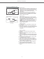
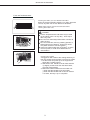
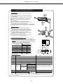
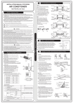
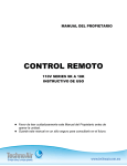
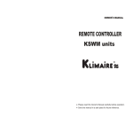
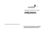
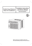
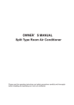
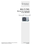
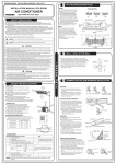
INVERTER SERIES H3
User and installation manual
MUPR-H3
CL 20 801 a CL 20 804
English
INDEX:
USER MANUAL:
General information.........................................................................................................2
Safety precautions...........................................................................................................3
Operating instructions......................................................................................................5
Detector and troubleshooting.........................................................................................12
INSTALLATION MANUAL:
Installation......................................................................................................................15
Indoor unit installation....................................................................................................16
Outdoor unit installation.................................................................................................21
REMOTE CONTROLLER:
Remote setup................................................................................................................24
Technical specifications of the remote controller ..........................................................25
Operation of the remote controller.................................................................................29
Deshumidifier of the remote controller...........................................................................30
USER´S MANUAL
Before using your air conditioner, please read
this manual carefully and keep it for future reference..
INVERTER SPLIT-TYPE
ROOM AIR CONDITIONER
The design and specifications are subject to
change without prior notice for
product improvement. Consult with the sales
agency or manufacturer for details.
Read This Manual:
Inside you will find many helpful hints on how to use and
maintain your air conditioner properly.
Just a little preventative care on your part can save you
a great deal of time and money over the life of your air
conditioner.
You'll find manyanswers to common problems in the
chart of troubleshooting tips. If you review the chart of
Troubleshooting Tips first, you may not need to call for
service.
1
GENERAL INFORMATION
CAUTION
Contact an authorised service technician for repair or maintenance of this unit.
Contact the authinstaller for installation of this unit.
This appliance is not intended for use by persons(including children) with reduced
physical, sensory or mental capabilities, or lack of experience and knowledge, unless
they have been given supervision or instruction concerning use of the appliance by a
person responsible for their safety.
Young children should be supervised to ensure that they do not play with the
air conditioner.
If the power cord is to be replaced, replacement work shall be performed by
authorised personnel only.
Installation work must be performed in accordance with the national wiring
standards by authorised personnel only.
When using this air conditioner in the European countries, the following
informations must be followed:
DISPOSAL: Do not dispose this product as unsorted municipal waste. Collection
of such waste separately for special treatment is necessary.
It is prohibited to dispose of this appliance in domestic household waste.
For disposal, there are several possibilities:
A) The municipality has established collection systems, where electronic waste can
be disposed of at least free of charge to the user.
B) When buying a new product, the retailer will take back the old product at least
free of charge.
C) The manufacture will take back the old appliance for disposal at least free of
charge to the user.
D) As old products contain valuable resources, they can be sold to scrap metal
dealers.
Wild disposal of waste in forests and landscapes endangers your health when
hazardous substances leak into the ground-water and find their way into the food
chain.
2
SAFETY PRECAUTIONS
To prevent injury to the user or other people and property damage, the following instructions
must be followed. Incorrect operation due to ignoring of instructions may cause harm or damage.
The seriousness is classified by the following indications.
WARNING
This symbol indicates the possibility of death or serious injury.
CAUTION
This symbol indicates the possibility of injury or damage to property.
Meanings of symbols used in this manual are as shown below.
Never do this.
Always do this.
WARNING
!
!
!
!
!
Connect with the power
properly.
Do not operate or stop the
unit by switching on or off
the power.
Do not damage or use an
unspecified power cord.
Otherwise, it may cause electric
shock or fire due to excess heat
generation.
It may cause electric shock or fire
due to heat generation.
It may cause electric shock
or fire.
Do not modify power cord
length or share the outlet
with other appliances
It may cause electric shock
or fire due to heat generation.
Do not operate with wet
hands or in damp
environment.
Do not direct airflow at
room occupants only.
It may cause electric shock.
This could damage your
health.
Always ensure effective
earthing.
Do not allow water to run
into electric parts.
No earthing may cause
electric shock.
It may cause failure of
machine or electric shock.
Always install circuit
breaker and a dedicated
power circuit.
No installation may cause
fire and electric shock.
Disconnect the power if
strange sounds, smell, or
smoke comes from it.
It may cause fire and
electric shock.
Do not drink water drained
from air conditioner.
Do not open the unit
during operation.
It contains contaminants and
could make you sick.
It may cause electric shock.
Use the correctly rated
breaker or fuse.
Do not use the power cord
close to heating appliances.
Do not disassemble or
modify unit.
There is risk of fire or
electric shock.
It may cause fire and
electric shock.
It may cause failure and
electric shock.
!
Do not use the power cord near
flammable gas or combustibles, such
as gasoline, benzene, thinner, etc.
Ventilate room before operating air
conditioner if there is a gas leakage
from another appliance.
It may cause explosion, fire and, burns.
It may cause an explosion or fire.
3
SAFETY PRECAUTIONS
CAUTION
!
!
!
Ventilate the room well
when used together
with a stove, etc.
When the air filter is to be
removed, do not touch the
metal parts of the unit.
Do not clean the air
conditioner with water.
It may cause an injury.
Water may enter the unit and
degrade the insulation. It may
cause an electric shock.
An oxygen shortage
may occur.
When the unit is to be
cleaned, switch off, and turn
off the circuit breaker.
Do not put a pet or house
plant where it will be
exposed to direct air flow.
Do not use for
special purposes.
Do not clean unit when
power is on as it may cause
fire and electric shock, it may
cause an injury.
This could injure the pet or
plant.
Stop operation and close
the window in storm or
hurricane.
Do not place obstacles
around air-inlets or inside
of air-outlet.
Do not use this air conditioner to preserve precision devices, food, pets,
plants, and art objects.
It may cause deterioration
of quality, etc.
Turn off the main power
switch when not using
the unit for a long time.
Operation with windows
opened may cause wetting
of indoor and soaking of
household furniture.
It may cause failure of
appliance or accident.
Do not use strong detergent
such as wax or thinner. Use
a soft cloth for cleaning.
!
Appearance may be
deteriorated due to change
of product color or
scratching of its surface.
Do not place heavy object on the
power cord and take care so that
the cord is not compressed.
Ensure that the installation bracket of
the outdoor appliance is not damaged
due to prolonged exposure.
If bracket is damaged, there
is concern of damage due to
falling of unit.
!
Use caution when unpacking
and installing. Sharp edges
could cause injury.
There is danger of fire or
electric shock.
4
!
It may cause failure of
product or fire.
!
Always insert the filters
securely. Clean filter
once every two weeks.
Operation without filters
may cause failure.
! If water enters the
unit, turn the unit off
and disconnect the
power , contact a
qualified service
technician.
OPERATING INSTRUCTIONS
Parts names
Indoor unit
Indoor unit
2
4
1.
2.
3.
4.
5.
6.
7.
8.
3
1
5
7
6
AUTO
9
SET
TEMP
COO
DRY L
HEAT
ERAT
URE
Outdoor unit
( C)
FAN
HIGH
MED
LOW
TEMP
MOD
E
ON/O
FF
SWIN
G
FAN
SLEE
P
DIRECAIR
TION
8
Front panel
Air inlet
Air filter
Air outlet
Horizontal air flow grille
Vertical air flow louver
Display panel
Remote controller
SPEE
D
TIME
R ON
RESET
LOCK
TIME
LED
DISPL
AY
R OFF
TURB
O
9. Connecting pipe, drain hose
10. Air inlet (side and rear)
11. Air outlet
Outdoor unit
10
NOTE:
All the pictures in this manual are for
explanation purpose only. Your air
conditioner may be slightly different.
The actual shape shall prevail.
11
AUTO indicator:
This indicator illuminates when the air
conditioner is in AUTO operation.
2 DEFROST Indicator
(For cooling& heating model only):
This indicator illuminates when the air
conditioner starts defrosting automatically
or when the warm air control feature is
activated in heating operation.
3 DIGITAL DISPLAY:
Displays the current setting temperature
or malfunction code when the air conditioner
is in operation.
4 OPERATION indicator:
The indicator flashes once every second
after power is on and illuminates when the
air conditioner is in operation.
5 TIMER indicator:
The indicator illuminates when TIMER is
set ON/OFF.
1
Indicator Lights on Display panel
The display panel on the indoor unit
would look like one of the following:
For cooling only models(>21000Btu/h
unit), 2 indicator light is FAN ONLY.
Signal
receptor
1
2
3
4
5
5
OPERATING INSTRUCTIONS
NOTE: This manual does not include Remote Controller Operations, see the
<<Remote Controller Instruction>> packed with the unit for details.
Operating temperature
Mode
Temperature
Room temperature
Outdoor temperature
Heating operation
Cooling operation
30
17 62
0
50
32
122
O
O
O
O
-15 C~50 C/5 F~122 F
(For the models with low
temperature cooling system)
-15
5
86
30
86
Drying operation
10
0
32
50
50
122
CAUTION:
1. If air conditioner is used outside of the above conditions, certain safety protection
features may come into operation and cause the unit to function abnormally.
2. Room relative humidity less than 80%. If the air conditioner operates in excess of this
figure, the surface of the air conditioner may attract condensation. Please sets the vertical
air flow louver to its maximum angle (vertically to the floor), and set HIGH fan mode.
3. Optimum performance will be achieved within these operating temperature.
Suggestion: For the unit adopts an Electric Heater, when the outside ambient temperature
is below 0 OC(32 OF), we strongly recommend you to keep the machine plugged in order to
guarantee it running smoothly.
Manual operation
Manul operation can be used temporarily in case the remote controller is disable or
maintenance necessary.
NOTE: The unit must be turned off before
operating the manual control button. If the
unit is operational, continue pressing the
manual control button until the unit is off.
1 Open and lift the front panel up to an angle
until it remains fixed with a clicking sound.
2 One press of the manual control button will
lead to the forced AUTO operation. If press
the button twice within five seconds, the unit
will operate under forced COOL operation.
3 Close the panel firmly to its original
position.
Panel
Manual control
button
CAUTION:
This button is used for testing purposes
only. You had better not choose it.
To restore the remote controller operation,
use the remote controller directly.
AUTO/COOL
6
OPERATING INSTRUCTIONS
Airflow direction control
Adjust the air flow direction properly otherwise, it
might cause discomfort or cause uneven room
temperatures.
Adjust the horizontal louver using the remote
controller.
Adjust the vertical louver manually.
Range
To set the vertical air flow(Up--Down) direction
Perform this function while the unit is in operation.
Use the remote controller to adjust the air flow
direction. The horizontal louver can be moved at
O
a range of 6 for each press, or swing up and down
,,
automatically. Please refer to the REMOTE
,,
CONTROLLER OPERATION MANUAL for details.
To set the horizontal air flow direction (left - right)
Move the vertical louver manually to adjust the air flow
in the direction you prefer.
IMPORTANT : Before adjusting the vertical louvers, the
supply power must be disconnected.
For some models, the vertical louver can be adjusted
by using the remote controller. Please refer to the ,,
,,
REMOTE CONTROLLER OPERATION MANUAL
for details.
Vertical
louver
CAUTION
Range
Do not operate the air conditioner for long periods with
the air flow direction set downward in cooling or
dehumidifying mode. Otherwise, condensation may
occur on the surface of the horizontal louver causing
moisture to drop on to the floor or on furnishings.
Do not move the horizontal louver manually unless it is
necessary. Always use the remote controller.
When the air conditioner is started immediately after it
was stopped, the horizontal louver might not move for
approximately 10 seconds.
Open angle of the horizontal louver should not be set
too small, as COOLING or HEATING performance may
be impaired due to too restricted air flow area.
Do not operate unit with horizontal louver in closed
position.
When the air conditioner is connected to power (initial
power), the horizontal louver may generate a sound for
10 seconds, this is a normal operation.
7
OPERATING INSTRUCTIONS
How the air conditioner works
SLEEP operation
7 hours timer off
Set
Temperature
1 hour
1 hour
Cooling
SLEEP operation
7 hours timer off
Set
Temperature
1 hour 1 hour
Heating
AUTO operation
When you set the air conditioner in AUTO mode, it will
automatically select cooling, heating(cooling/heating
models only), or fan only operation depending on what
temperature you have selected and the room
temperature.
The air conditioner will control room temperature
automatically round the temperature point set by you.
If the AUTO mode is uncomfortable, you can select
desired conditions manually.
SLEEP operation
When you push SLEEP button on remote controller
during cooling, heating(cooling & heating models only),
or AUTO operation , the air conditioner will
automatically increase (cooling) or decrease (heating)
per hour for the first 2 hours, then hold
steady for the next 5 hours, after that it will switch off.
This characteristic maintains both enery saving and
comfort in night operation.
DRYING operation
The fan speed will be automatically controlled under
dry operation.
During the dry operation, if the room temperature is
lower than 10OC(50OF), the compressor stops operation
and restarts until the room temperature is above
12OC(54OF).
Optimal operation
To achieve optimal performance, please note the
following:
Adjust the air flow direction correctly so that it is not
directed on people.
Adjust the temperature to achieve the highest comfort
level. Do not adjust the unit to excessive temperature
levels.
Close doors and windows on COOL or HEAT modes,
or performance may be reduced.
Use TIMER ON button on the remote controller to
select a time you want to start your air conditioner.
Do not put any object near air inlet or air outlet, as the
efficiency of the air conditioner may be reduced and
the air conditioner may stop running.
Clean the air filter periodically, otherwise cooling or
heating performance may be reduced.
Do not operate unit with horizontal louvre in closed
position.
8
OPERATING INSTRUCTIONS
Care and maintenance
Cleaning the Grille, Case and Remote Controller
Turn the system off before cleaning. To clean, wipe with
a soft, dry cloth. Do not use bleach or abrasives.
NOTE: Supply power must be disconnectd before
cleaning the indoor unit.
CAUTIONS
Filter Handle
A cloth dampened with cold water may be used
on the indoor unit if it is very dirty. Then wipe it
with a dry cloth.
Do not use a chemically treated cloth or duster to
clean the unit.
Do not use benzine, thinner, polishing powder, or
similar solvents for cleaning. These may cause
the plastic surface to crack or deform.
Never use water hotter than 40OC/104OF to clean
the front panel, it could cause deformation of
discoloration.
Cleaning the air filter
A clogged air filter reduces the cooling efficiency of
this unit. Please clean the filter once every 2 weeks.
1. Lift the indoor unit panel up to an angle until it
stops with a clicking sound.
2. Take hold of the handle of the air filter and lift it
up slightly to take it out from the filter holder,
then pull it downwards.
3. Remove the AIR FILTER from the indoor unit.
Clean the AIR FILTER once two weeks.
Clean the AIR FILTER with a vacuum cleaner
or water, then dry it up in cool place.
9
OPERATING INSTRUCTIONS
Air freshening filter
1
Air freshening filter
4. Remove the Air Freshening Filter from its support
frame (on some models).
(The optional filter include :Plasma Dust Collector/
Silver Ion filter /Bio filter /Vitamin C filter/3M air
purifier filter, etc. The removing and installation
methods are slightly different, see the pictures
marked 1 and 2 on the left.
Clean the air freshening filter at least once a
month, and replace it every 4-5 months.
Clean it with vacuum cleaner, then dry it in cool
place.
Do not touch the Plasma Dust Collector
Filter within 10 minutes after opening the
front panel, it may cause an electric shock.
5. Install the air freshening filter back into position.
6. Insert the upper portion of air filter back into the
unit, taking care that the left and right edges line
up correctly and place filter into position.
Maintenance
2
If you plan to idle the unit for a long time, perform
the following:
(1) Operate the fan for about half a day to dry the
inside of the unit.
(2) Stop the air conditioner and disconnect power.
Remove the batteries from the remote controller.
(3) The outdoor unit requires periodic maintenance
and cleaning. Do not attempt to do this yourself.
Contact your dealer or servicer.
Checks before operation
Check that the wiring is not broken off or
disconnected.
Check that the air filter is installed.
Check if the air outlet or inlet is blocked after the
air conditioner has not been used for a long time.
Caution
Do not touch the metal parts of the unit when
removing the filter. Injuries can occur when
handling sharp metal edges.
Do not use water to clean inside the air conditioner.
Exposure to water can destroy the insulation,
leading to possible electric shock.
When cleaning the unit, first make sure that the
power and circuit breaker are turned off.
10
OPERATING INSTRUCTIONS
The following events may occur during normal operation.
1. Protection of the air conditioner.
Compressor protection
The compressor can't restart for 3 minutes after it stops.
Anti-cold air (Cooling and heating models only)
The unit is designed not to blow cold air on HEAT mode, when the indoor heat exchanger is in
one of the following three situations and the set temperature has not been reached.
A) When heating has just starting.
B) Defrosting.
C) Low temperature heating.
The indoor or outdoor fan stop running when defrosting (Cooling and heating models only).
Defrosting (Cooling and heating models only)
Frost may be generated on the outdoor unit during heat cycle when outdoor temperature is low
and humidity is high resulting in lower heating efficiency of the air conditioner.
During this condition air conditioner will stop heating operation and start defrosting automatically.
The time to defrost may vary from 4 to 10 minutes according to the outdoor temperature and
the amount of frost build up on the outdoor unit.
2. A white mist coming out from the indoor unit
A white mist may generate due to a large temperature difference between air inlet and air outlet
on COOL mode in an indoor environment that has a high relative humidity.
A white mist may generate due to moisture generated from defrosting process when the air
conditioner restarts in HEAT mode operation after defrosting.
3. Low noise of the air conditioner
You may hear a low hissing sound when the compressor is running or has just stopped running.
This sound is the sound of the refrigerant flowing or coming to a stop.
You can also hear a low "squeak" sound when the compressor is running or has just stopped
running. This is caused by heat expansion and cold contraction of the plastic parts in the unit
when the temperature is changing.
A noise may be heard due to louver restoring to its original position when power is first turned on.
4. Dust is blown out from the indoor unit.
This is a normal condition when the air conditioner has not been used for a long time or during first
use of the unit.
5. A peculiar smell comes out from the indoor unit.
This is caused by the indoor unit giving off smells permeated from building material, from furniture,
or smoke.
6. The air conditioner turns to FAN only mode from COOL or HEAT (For cooling and
heating models only) mode.
When indoor temperature reaches the temperature setting on air conditioner, the compressor will
stop automatically, and the air conditioner turns to FAN only mode. The compressor will start again
when the indoor temperature rises on COOL mode or falls on HEAT mode (For cooling and heating
models only) to the set point.
11
DETECTOR AND TROUBLESHOOTING
7. Dripping water may generate on the surface of the indoor unit when cooling in a high
relatively humidity (relative humidity higher than 80%). Adjust the horizontal louver to
the maximum air outlet position and select HIGH fan speed.
8. Heating mode (For cooling and heating models only)
The air conditioner draws in heat from the outdoor unit and releases it via the indoor unit
during heating operation. When the outdoor temperature falls, heat drawn in by the air
conditioner decreases accordingly. At the same time, heat loading of the air conditioner
increases due to larger difference between indoor and outdoor temperature. If a
comfortable temperature can't be achieved by the air conditioner, we suggest you use a
supplementary heating device.
9. Auto-restart function
Power failure during operation will stop the unit completely.
For the unit without Auto-restart feature, when the power restores, the OPERATION indicator
on the indoor unit starts flashing. To restart the operation, push the ON/OFF button on the
remote controller. For the unit with Auto-restart feature, when the power restores, the unit
restarts automatically with all the previous settings preserved by the memory function.
For some models, the machine is special designed with Auto-restart function for the open angle
of the horizontal louver.Power failure during operation or pressing the ON/OFF button on the
remote controller will stop the unit completely.When the power restores or pressing the ON/OFF
button on the remote controller again,the unit restarts automatically with all the previous settings
including the open angle of the horizontal louver by the memory function.So we strongly suggest
that the open angle of the horizontal louver should not be set too small,in case the condensed
water forms and drops from the horizontal louver. Press the AUTO/COOL button under the
front panel and the open angle of the horizontal louver will be restored to the standard angle
when the condensed water forms on the horizontal louver.
10. Lightning or a car wireless telephone operating nearby may cause the unit to malfunction.
Disconnect the unit with power and then re-connect the unit with power again. Push the
ON/OFF button on the remote controller to restart operation.
12
DETECTOR AND TROUBLESHOOTING
Troubleshooting Tips
If one of the following faults occurs, stop the air conditioner immediately, disconnect the power
and then connect it in again. If the problem still exists, disconnect the power and contact the
nearest customer service center.
OPERATION/RUN indicator or other indicators continue flashing.
Trouble
Fuse blows frequently or circuit breaker trips frequently.
Other objects or water fall into the air conditioner.
The remote controller won't work or works abnormally.
If one of the following code appears on the display area :
E0,E1,E2,E3.....or P0,P1,P2,P3......
Cause
Malfunctions
Unit does not
What should be done?
Wait for power to be restored.
Power cut
start
Unit may have become unplugged.
Check that plug is securely in wall
receptacle.
Fuse may have blown.
Replace the fuse.
Battery in Remote controller may
have been exhausted.
Replace the battery.
The time you have set with timer
is incorrect.
Wait or cancel timer setting.
Unit not cooling
Inappropriate temperature
Set temperature correctly. For
or heating
setting.
detailed method please refer to
(Cooling/ heating
models only)
"Using remote control" section.
Air filter is blocked.
Clean the air filter.
while air flowing
Doors or Windows are open.
Close the doors or windows.
out from the air
Air inlet or outlet of indoor or
outdoor unit has been blocked.
Clear obstructions away first, then
restart the unit.
Compressor 3 minutes
protection has been activated.
Wait.
room very well
cond tioner
i
If the trouble has not been corrected, please contact a local dealer or the nearest customer
service center. Be sure to inform them of the detailed malfunctions and unit model.
Notes: Do not attempt to repair the unit yourself.
Always consult an authorised service provider.
13
INSTALLATION MANUAL
ROOM AIR CONDITIONER
(Split Wall-Mounted Type)
14
INSTALLATION
INSTALLATION PRECAUTIONS
Please read this installation manual carefully before operating the unit to ensure correct installation.
If the power cord is damaged, replacement work shall be performed by authorised personnel only.
Installation work must be performed in accordance with the national wiring standards by authorised
personnel only.
Contact an authorized service technician for repair, maintenance and installation of this unit.
This appliance is not intended for use by persons(including children) with reduced physical, sensory
or mental capabilities, or lack of experience and knowledge, unless they have been given supervision
or instruction concerning use of the appliance by persons responsible for their safety.
Children should be supervised to ensure that they do not play with the appliance.
All the pictures in the instructions are for explanation purposes only. The actual shape should prevail.
The design and specifications are subject to change without prior notice for product improvement.
Consult with the sales agency or manufacturer for details.
SAFETY PRECAUTIONS
Please read these safety precautions carefully before installation
Be sure to follow all the precautions below, they are all important for ensuring safety.
WARNING
This symbol indicates the possibility of death or serious injury.
CAUTION
This symbol indicates the possibility of injury or damage to property.
WARNING
1) Install according to this installation instructions strictly. If installation is defective, it will cause water
leakage, electrical shock,or fire.
2) Use the included accessories parts and specified parts for installation. otherwise, it will cause the set
to fall, water leakage, electrical shock fire.
3) Install at a strong and firm location which is able to withstand the set s weight. If the strength is not
enough or installation is not properly done, the set will drop and cause injury.
4) For electrical work, follow the local national wiring standard, regulation and this installation instructions.
An independent circuit and single outlet must be used. If electrical circuit capacity is not enough or
defect found in electrical work, it will cause electrical shock fire.
5) Use the specified cable and connect tightly and clamp the cable so that no external force will be acted
on the terminal. If connection or fixing is not perfect, it will cause heat-up or fire at the connection.
6) Wiring routing must be properly arranged so that control board cover is fixed properly. If control board
cover is not fixed perfectly, it will overheat at connection point of terminal, fire or electrical shock.
7) When carrying out piping connection, take care not to let air substances other than the specified
refrigerant go into refrigeration cycle. Otherwise, it will cause lower capacity, abnormal high pressure
in the refrigeration cycle, explosion and injury.
8) Do not modify the length of the power supply cord or use of extension cord, and do not share the
single outlet with other electrical appliances. Otherwise, it will cause fire or electrical shock.
CAUTION
1) This equipment must be grounded and installed with ground leakage current breaker. It may cause
electrical shock if grounding is not perfect.
2) Do not install the unit at place where leakage of flammable gas may occur. In case gas leaks and
accumulates at surrounding of the unit, it may cause fire.
3) Carry out drainage piping as mentioned in installation instructions. If drainage is not perfect, water
may enter the room and damage the furniture.
15
OUTDOOR UNIT INSTALLATION
SELECT THE BEST LOCATION
Indoor unit
There should not be any heat source or stream
near the unit.
There should not be any obstacles blocking the
air circulation.
A place where air circulation in the room is good.
A palce where drainage can be easily done.
A palce where noise prevention is taken into
consideration.
Do not install the unit near the door way.
Ensure the spaces indicated by arrows from the
wall,ceiling,fence or other obstacles.
There should not be any direct sunlight. If unavoidable,
sunlight prevention should be taken into consideration.
Outdoor unit
If an awning is built over the unit to prevent
direct sunsight or rain,be careful that heat
radiation from the condenser is not obstructed.
There should not be any animal or plant which
could be affected by hot air discharged.
Keep the spaces indicated by arrow from wall
ceiling, fence or other obstacles.
Do not place any obstacles which may cause
a short circuit of the discharged air.
Settlement of outdoor unit
Anchor the outdoor unit with a bolt and nut
10 or
8 tightly and horizontally on a concrete or rigid mount.
NOTE: The outdoor unit you purchase may be like one
of the following. Install the outdoor unit according to the
dimension as indicated in the table below:
Mounting dimensions
A(mm)
B(mm)
700x540x240
458
250
685x430x260
460
276
780x540x250
549
760x590x285
530
290
845x700x320
560
335
775x545x310
600
320
670x540x265
481
276
W
A
Air inlet
276
B
Air inlet
D
Outdoor unit dimension
mm(WxHxD)
Air outlet
ACCESSORIES
Name of Accessories
Qty
1
2
3
Installation Plate
Clip Anchor
Self-tapping Screw A ST3.9x25
1
5-8(depending on models)
4
5
Seal(For cooling & heating models only)
1
Drain Joint(For cooling & heating models only
6.35
Connecting Liquid side
9.52
pipe
9.52
Assembly
Gas side
12.7
16
Remote controller
Self-tapping Screw B ST2.9x10
optional
Remote controller holder
parts
1
Number
6
7
8
9
5-8(depending on models)
Parts you must purchase. The pipe
size differ from appliance to appliance.
Consult the technician for the proper
size.
1
2
1
NOTE : Except the above parts provided,the other parts needed during installation you must
purchase.
16
OUTDOOR UNIT INSTALLATION
1
NOTE:
INSTALLATION PLATE MOUNTING
The mounting wall is strong and solid enough to prevent it from the vibration.
Fit the Installation Plate
1. Fit the installation plate horizontally
on structural parts of the wall with
spaces around the installation plate.
2. If the wall is made of brick, concrete
or the like, drill five or eight 5mm
diameter holes in the wall.Insert Clip
anchor for appropriate mounting screws.
3. Fit the installation plate on the wall
with five or eight type " A " screws.
NOTE:
Fit the Installation Plate and drill
holes in the wall according to the
wall structure and corresponding
mounting points on the installation
plate. The installation plate provided
with the machine differ from appliance
to appliance.
(Dimensions are in " mm " unless
otherwise stated)
Correct orientation
of Installation Plate
205
930
2
DRILL A HOLE IN THE WALL
1. Determine hole positions according to left and right
side of the installation plate. The hole center is obtained
by measuring the distance as shown in the diagram above.
2. Dirll the piping plate hole with 65mm hole-core drill.
3. Drill the piping hole at either the right or the left and the
hole should be slightly slanted to the outdoor side.
4. Always take steps to protect the pipe when drilling metal
grid,metal plate or the like.
17
INDOOR UNIT INSTALLATION
3
CONNECT THE CABLE TO THE INDOOR UNIT
Electrical work
Electric safety regulations for the initial Installation
1. If there is serious safety problem about the power supply, the technicians should refuse to install
the air conditioner and explain to the client until the problem is solved.
2. Power voltage should be in the range of 90%~110%of rated voltage.
3. The surge protector and main power switch with a 1.5 times capacity of Max. Current of the
unit should be installed in power circuit.
4. Ensure the air conditioner is grounded well.
5. According to the attached Electrical Connection Diagram located on the panel of the outdoor unit
to connect the wire.
6. All wiring must comply with local and national electrical codes and be installed by qualified and
skilled electricians.
7. An all-pole disconnection device which has at least 3mm separation distance in all pole and a residual
current device(RCD) with the rating of not exceeding 30mA shall be incorporated in the fixed wiring
according to the national rule.
8. An individual branch circuit and single receptacle used only for this air conditioner must be
available. See the following table for suggested wire sizes and fuse specifications:
Minimum nor minal cross-sectional area of conductors:
Rated cur rent
of appliance
(A)
>3 and 6
>6 and 10
>10 and 16
>16 and 25
Nominal cross-sectional
area
(mm2)
NOTE:
The cable size and the current of thefuse
or switch are determined by the maximum
current indicated on the nameplate which
located on the side panel of the unit.
Please refer to the nameplate before
selecting the cable, fuse and switch.
0.75
1
1.5
2.5
Connect the cable to the indoor unit
NOTE:
Before performing any electrical work, turn off the main power to the system.
1. For model A, first remove the front cover on chassis by loosening the screw, then remove the front
cover of frame as shown below. For model B, just open the panel up, then remove the electrical control
box cover by loosening the screw.
3. The indoor power cord type is H05VV-F or H05V2V2-F, the outdoor power cord and interconnected
cord type is H07RN-F. Ensure the colour of wires of outdoor unit and the terminal Nos. are the same
to the indoor s respectively.
5. Wrap those cables not connected with terminals with insulation tapes, so that they will not touch
any electrical components. Secure the cable onto the control board with the cord clamp.
NOTE: If used as MONO unit, for the standby control needs, the cross section area of cable connected
to L(1), 1, 2(N) must be sufficient for the maximum system current. The maximum system current is
equal to the sum of indoor unit and outdoor unit rated current. If used as MULTI unit, L(1) on the terminal
block does not need to be connected.
,
Model A
Model B
1
Terminal block ofi ndoor unit
Hold here by hand
and loosen the screw.
Panel
L(1) 1 2(N)
2
S
Press here to disengage
the hook from the unit,
pull it downwards to
remove the cover
To outdoor unit
3
Remove the front panel
of on the frame
Electrical conrol
box cover
Front cover of frame
Front cover on chassis
4
CONNECTIVE PIPE AND DRAINAGE INSTALLATION
Drainage
1. Run the drain hose sloping downward.
Do not install the drain hose as illustrated
in wrong figures.
2. When connecting extension drain hose,
insulate the connecting part of extension
drain hose with a shield pipe, do not let
the drain hose slack.
Right
18
Wrong
INDOOR UNIT INSTALLATION
Connective pipe installation
1. For the left-hand and right-hand piping,
remove the pipe cover from the side panel.
2. For the rear-right-hand and rear-left-hand
piping, install the piping as shown.
3. Bundle the tubing, connecting cable, and
drain hose with tape securely, evenly as
shown in Figure on the right.
Because the condensed water from rear
of the indoor unit is gathered in ponding
box and is piped out of room. Do not put
anything else in the box.
CAUTION
Connect the indoor unit first, then the
outdoor unit.
Do not allow the piping to let out from the
back of the indoor unit.
Be careful not to let the drain hose slack.
Heat insulation should be done to the
extension drain hose of indoor unit.
Be sure that the drain hose is located at
the lowest side of the bundle. Locating at
the upper side can cause drain pan to
overflow inside the unit.
Never intercross nor intertwist the power
wire with any other wiring.
Rear-right piping
Indoor unit installation
1. Pass the piping through the hole in the wall.
2. Hook the indoor unit onto the upper portion
of installation plate(Engage the indoor unit with
the upper edge of the installation plate). Ensure
the hooks are properly seated on the installation
plate by moving it in left and right.
3. Piping can easily be made by lifting the indoor
unit with a cushioning material between the
indoor unit and the wall. Get it out after finish
piping.
4. Press the lower left and right side of the unit
against the installation plate until hooks
engages with the their slots.
19
OUTDOOR UNIT INSTALLATION
1
OUTDOOR INSALLATION PRECAUTION
Install the outdoor unit on a rigid base to prevent increasing noise level and vibration.
Determine the air outlet direction where the discharged air is not blocked.
In the case that the installation place is exposed to strong wind such as a seaside, make
sure the fan operating properly by putting the unit lengthwise along the wall or using a dust
or shield plates.
Specially in windy area, install the unit to prevent the admission of wind. If need suspending
installation, the installation bracket should accord with technique requirement in the
installation bracket diagram. The installation wall should be solid brick, concrete or the same
intensity construction, or actions to reinforce, damping supporting should be taken.
The connection between bracket and wall, bracket and the air conditioner should be firm,
stable and reliable.
Be sure there is no obstacle which block radiating air.
Incorrect
Correct
Barrier
Strong
wind
Strong
wind
2
DRAIN JOINT INSTALLATION
NOTE:
The drain joint is slightly different according to the
different outdoor unit.
For the drain joint with the seal(Fig.A), first fit the seal onto
the drain joint, then insert the drain joint into the base pan
hole of outdoor unit, rotate 90 to securely assemble them.
To install drain joint as shown in Fig.B, insert the drain
joint into the base pan hole of outdoor unit until it remains
fixed with a clicking sound. Connecting the drain joint with
an extension drain hose (Locally purchased), in case of the
water draining off the outdoor unit during the heating mode.
Base pan hole
of outdoor unit
(A)
(B)
REFRIGERANT PIPE CONNECTION
Flaring
90O
1. Cut a pipe with a pipe cutter.
2. Put flare nuts on pipe/tube having
completed burr removal and flare the pipe.
3. Firmly hold copper pipe in a die in the
dimension shown in the table below.
Oblique Roughness Burr
Handle
"A"
3
Drain joint
Seal
Bar
Bar
A(mm)
Outer diam.
(mm)
Max.
Min.
6.35
1.3
0.7
9.52
1.6
1.0
12.7
16
1.8
2.2
1.0
2.0
Copper pipe
Indoor unit tubing
Outer
diam.
Tightening connection
Align pipes to be connected.
Sufficiently tighten the flare nut with fingers,
and then tighten it with a spanner and torque
wrench as shown.
Excessive torque can break nut depending
on installation conditions.
6.35mm
9.52mm
12.7mm
16mm
20
Clamp handle
Flare nut
Pipings
Tightening
torque(N.cm)
Additional tightening
torque(N.cm)
1500
(153kgf.cm)
2500
(255kgf.cm)
1600
(163kgf.cm)
3500
(357kgf.cm)
4500
(459kgf.cm)
3600
(367kgf.cm)
4700
(479kgf.cm)
2600
(265kgf.cm)
OUTDOOR UNIT INSTALLATION
4
CONNECT THE CABLE TO THE OUTDOOR UNIT
1. Remove the electrical control board cover from the outdoor unit by loosening the screw.
2. Connect the connective cables to the terminals as identified with their respective matched numbers
on the terminal block of indoor and outdoor units.
3. Secure the cable onto the control board with the cord clamp.
4. To prevent the ingress of water, form a loop of the connective cable as illustrated in the installation
diagram of indoor and outdoor units.
5. Insulate unused cords (conductors) with PVC-tape. Process them so they do not touch any electrical
or metal parts.
Terminal block of outdoor unit
Cover
Screw
To indoor unit
5
Power supply
AIR PURGING AND TEST OPERATION
1. Air purging
The indoor unit and tubing between the indoor and outdoor unit must be leak tested and evacuated
to remove any noncondensables and moisture from the system.
Check that each tube(both liquid and gas side tubes) between the indoor and outdoor units have
been properly connected and all wiring for the test run has been completed.
Pipe length and refrigerant amount:
Connective pipe length Air purging method
Less than 5m
Use vacuum pump
More than 5m
Use vacuum pump
Additional amount of refrigerant to be charged
Liquid side: 6.35mm
R22: (Pipe length-5)x30g/m
R410A: (Pipe length-5)x20g/m
Liquid side: 9.52mm:
R22: (Pipe length-5)x60g/m
R410A: (Pipe length-5)x40g/m
For the R410A refrigerant model, make sure the refrigerant added into air conditioner is liquid
form in any cases.
When relocating the unit to another place, using vacuum pump to perform evacuation.
CAUTION
Open the valve stem until it hits against
the stopper. Do not try to open it further.
Securely tighten the valve stem cap with
a spanner or the like.
Valve stem cap tightening torque. See
Tightening torque table.
Refrigerant
Outdoor
unit
A
Gas side
Liquid side
Flare nut
Indoor
unit
C
B
Packed valve
21
Stopper
Cap
D
Flare nut
Valve body
Valve stem
OUTDOOR UNIT INSTALLATION
2. When using the Vacuum Pump
1. Completely tighten the flare nuts, A, B, C, D, connect
the manifold valve charge hose to a charge port of the
Manifold valve
packed valve on the gas pipe side.
Compound meter Pressure gauge
2. Connect the charge hose connection to the vacuum
pump.
-76cmHg
3. Fully open the handle Lo of the manifold valve.
4. Operate the vacuum pump to evacuate. After starting
Handle Hi
Handle Lo
evacuation, slightly loose the flare nut of the packed
Charge
hose
valve on the gas pipe side and check that the air is
Charge hose
entering. (Operation noise of the vacuum pump changes
Vacuum pump
and a compound meter indicates 0 instead of minus)
5. After the evacuation is complete, fully close the handle
Lo of the manifold valve and stop the operation of the
vacuum pump.
Make evacuation for 15 minutes and more and check
Packed valve
5
that the compound meter indicates -76cmHg(-1.0x10 Pa).
O
6. Turn the stem of the packed valve B about 45 counterclockwise for 6~7 seconds after the gas coming out, then
tighten the flare nut again. Make sure the pressure display
in the pressure indicator is a little higher than the atmosphere
pressure.
7. Remove the charge hose from the Low pressure charge hose.
8. Fully open the packed valve stems B and A.
9. Securely tighten the cap of the packed valve.
3. Safety and leakage check
1. Soap water method:
Apply a soap water or a liquid neutral detergent on the indoor
unit connections and outdoor unit connections by a soft brush
to check for leakage of the connecting points of the piping. If
bubbles come out, it indicates that the pipes have leakage.
2. Leak detector
Use the leak detector to check for leakage.
Indoor unit
check point
D
C
B
A
Cover
Outdoor unit
check point
CAUTION
A: Lo packed valve B: Hi packed valve
C and D are ends of indoor unit connection.
4. Test running
Perform test operation after completing gas leak check at the flare nut connections and electrical
safety check.
Check that all tubing and wiring have been properly connected.
Check that the gas and liquid side service valves are fully open.
1. Connect the power, press the ON/OFF button on the remote controller to turn the unit on.
2. Use the MODE button to select COOL, HEAT, AUTO and FAN to check if all the functions works
well.
O
3. When the ambient temperature is too low(lower than 17 C), the unit cannot be controlled by the
remote controller to run at cooling mode, manual operation can be taken. Manual operation is
used only when the remote controller is disable or maintenance necessary.
Hold the panel sides and lift the panel up to an angle until it remains fixed with a clicking sound.
Press the Manual control button to select the AUTO or COOL, the unit will operate under Forced
AUTO or COOL mode(see User Manual for details).
4. The test operation should last about 30 minutes.
Manual control
button
AUTO/COOL
22
REMOTE CONTROLLER
Please read this Owner's Manual carefully before operation.
Save this manual in a safe place for future reference.
23
REMOTE SETUP
3. Set the starting & stopping time
3.1 Push the TIMER ON button, the remote controller will show
TIMER ON, the last set time for START operation and the
signal "h" will be shown on the DIGITAL display area. You
are now ready to readjust the TIMER ON to start the operation.
3.2 Push the TIMER ON button again to set the time you want to
start the operation.
3.3 Push the TIMER OFF button, the remote controller will show
TIMER OFF, the last set time for STOP operation and the
signal "h" will be shown on the DIGITAL display area. You
are now ready to reset the time to STOP operation.
3.4 Push the TIMER OFF button again to set the time you want to
stop the operation.
3.5 After setting the TIMER, there will be a one-half second delay
before the remote controller transmits the signal to the Air
Conditioner. Then , after approximately another 2 seconds, the
signal "h" disappears and the set temperature will re-appear on
the digital display.
Change the TIMER
To change the TIMER ON/OFF time, just press the corresponding
TIMER button and reset the time.
To cancel the TIMER ON/OFF setting, just adjust the TIMER time
to 0:00.
NOTE
The setting time is relative time. That is the time set is based
on the delay of the current time.
Warning
1. Be sure there are no obstacles between the remote controller
and the receiver of indoor unit otherwise the air conditioner will
not work.
2. Keep the Remote Controller away from any liquids.
3. Protect the remote controller from the high temperatures and
exposure to radiation.
4. Keep the indoor receiver out of direct sunlight or the Air Conditioner may malfunction.
5. Keep Remote Controller away from EMI(Electro-Magnetic
Interference) supplied by other household appliances.
24
TECHNICAL SPECIFICATIONS OF REMOTE CONTROLLER
Remote Controller Specification
Model
R51M/(C)E, R51M/BG(C)E, RG51M2/(C)E,
RG51A/(C)E, RG51M3/(C)E, RG51M3/BG(C)E,
RG51M8/(C)E,RG51M9/(C)E.
Rated Voltage
3.0V(Alkaline dry batteries LR03
2)
Lowest Voltage of CPU
2.0V
Emitting Signal
Transmission Distance 8m (when using 3.0 voltage,
it Gets 11m)
Environment
-5 C 60 C
~
Performance Features
1. Operating Mode: AUTO COOL DRY
HEAT(Cooling only model without) and FAN .
2. Timer Setting Function in 24 hours.
3. Indoor Setting Temperature Range : 17 C~30 C.
4. Full function of LCD (Liquid Crystal Display)
5. Back light emitting(only available for R51M(3)/BG(C)E models)
Features of the Remote controller buttons
NOTE:
: Indicates optional
button.
*
SET TEMPERATURE ( C)
FAN
HIGH
MED
LOW
AUTO
COOL
DRY
HEAT
TEMP
2
9
1
MODE
3
4*
SWING
5
6*
7*
ON/OFF FAN SPEED
SLEEP
RESET LOCK
AIR
DIRECTION
CLEAN
AIR
TIMER ON
TIMER OFF
LED
DISPLAY TURBO
*
*
14 and 15 buttons
are not available for
M odels RG51M2/(C)E.
8
10
11
12
13
14 *
15 *
* *
*
7 , 14 and 15
buttons are not available
for Models RG51M3/(C)E
and RG51M3/BG(C)E.
*
15 button is not
available for Models
R51M/(C)E and
R51M/BG(C)E.
*** * *
4 ,6 ,7 ,14 ,15 buttons
are not available for
Models RG51M9/(C)E.
** * *
6 ,7 ,14 ,15 buttons
are not available for
Models RG51M8/(C)E.
Fig. 1
25
TECHNICAL SPECIFICATIONS OF REMOTE CONTROLLER
TEMP Button :
Push this button to decrease the indoor
temperature setting.
TEMP Button
:
Push this button to increase the indoor
temperature setting .
MODE Selection Button:
Each time the button is pressed, the
operation mode is shifted in the direction of the arrow:
1
2
3
AUTO
NOTE:
COOL
DRY
HEAT
FAN
COOL only model has no HEAT feature.
4
SWING Button:
Push this switch button to activate auto
swing feature of the horizontal louver. Push it again to stop.
5
RESET Button:
When you press the recessed RESET button,
all current settings are cancelled and the control will return to
the initial settings.
6
AIR DIRECTION Button:
Press this button to change the swing
angle of the louver. The swing angle of the louver is 6o for
each press. When the louver swing at a certain angle which
would affect the cooling and heating effect of the air conditioner,
it would automatically change the swing direction . No symbol
will appear in the display area when press this button. (Not
applicable to units without this function).
7
LED DISPLAY Button:
Press this button to clear the digit
display in the air conditioner, press it again to activate it (Not
available for the units without LED display window).
8
FAN SPEED Button:
Used to select the Fan Speed in four stepsAUTO LOW MED or HIGH. Each time the button is pressed,
the fan speed mode is shifted.
9
ON/OFF Button:
Push this button to start operation, push the
button again to stop operation.
10
11
TIMER ON Button: Press this button to initiate the auto-on time
sequence. Each press will increase the auto-timed setting in 30
minutes increments. When the setting time displays 10, each
press will increase the auto-timed setting 60 minutes increments.
To cancel the auto-timed program, simply adjust the auto-on time
to 0.0.
SLEEP Button:
Press this button to go into the Energy-Saving
operation mode. Press it again to cancel. This function is only
can be used on COOL, HEAT and AUTO mode and maintain the
most comfortable temperature for you.
26
TECHNICAL SPECIFICATIONS OF REMOTE CONTROLLER
12
13
TIMER OFF Button:
Press this button to initiate the auto-off time
sequence. Each press will increase the auto-timed setting in 30
minutes increments. When the setting time displays 10, each
press will increase the auto-timed setting 60 minutes increments.
To cancel the auto-timed program, simply adjust the auto-off time
to 0.0.
LOCK Button:
When you press the recessed LOCK button, all
current settings are locked in and the remote controller does not
accept any operation except that of the LOCK. Press again to
cancel the LOCK mode.
14
TURBO Button:
Push this button to activate/cancel the Turbo
function which enables the unit to reach the preset temperature in
the shortest time.On cooling mode, the unit will blow strong cooling
air with super high fan speed. On heating mode (applicable to the
unit adopts PTC only), the PTC will bring fast heating operation.
15
CLEAN AIR Button(on some models):
When push this button,
the Ionizer or Plasma Dust Collector(depending on models) is
energized and will help to remove pollen and impurities from
the air.
Indicators on Display Panel
Display Panel
DIGITAL
DISPLAY area
1
TRANSMISSION Indicator
2
3
ON/OFF Indicator
OPERATION
MODE Indicator
4
4
OPERATION
MODE Indicator
7
LOCK Indicator
FAN SPEED Indicator
5
TIMER ON OFF
TIMER
DISPLAY Indicator
6
Fig. 2
1
DIGITAL DISPLAY area:
This area will show the set temperature
and, if in the TIMER mode, will show the ON and OFF settings of
the TIMER. If in the FAN mode, nothing is appeared.
2
TRANSMISSION Indicator:
This indicator flashes one time
when remote controller transmits signals to the indoor unit.
27
TECHNICAL SPECIFICATIONS OF REMOTE CONTROLLER
3
4
5
ON/OFF Indicator: This symbol appears when the unit is turned
on by the remote controller, and disappear when the unit is
turned off.
OPERATION MODE Indicator:
When press the MODE button,
it shows the current operating mode -- AUTO
COOL
DRY
HEAT (Cooling only model without)
mode.
LOCK Indicator: LOCK display is displayed by pushing the LOCK
button. Push the LOCK button to clear display.
TIMER DISPLAY Indicator:
This display area shows the settings
of the TIMER. That is, if only the starting time of operation is set,
it will display the TIMER ON. If only the turning off time of operation
is set, it will display the TIMER OFF. If both operations are set,
it will show TIMER ON-OFF which indicates you have chosen
to set both the starting time and off time.
6
7
FAN SPEED Indicator:
Press the FAN SPEED button to select
the desired fan speed setting (Auto-Low-Med-High). You selection
will be displayed in the LCD window except the Auto fan speed.
NOTE: All signs shown in the Fig.2 is for the purpose of clear
presentation. But during the actual operation only the relative functional signs are shown on the display panel.
Operating the Remote Controller
Install/Replace Batteries
The Remote Controller uses two alkaline dry batteries(LR03X2).
1. To install the batteries, slide the back cover of the battery
compartment and install the batteries according the
direction (+and -)shown on the Remote Controller.
2. To replace the old batteries, use the same method as
mentioned above.
NOTE
1. When replacing batteries, do not use old batteries or a different
type battery. This may cause the remote control
to malfunction.
2. If you do not use the remote controller for several weeks
remove the batteries. Otherwise battery leakage may damage
the remote controller.
3. The average battery life under normal use is about 6 months.
4. Replace the batteries when there is no answering beep from the
indoor unit or if the Transmission Indicator light fails to light.
5. Do not dispose batteries as unsorted municipal waste. Collection
of such waste separately for special treatment is necessary.
28
OPERATION OF THE REMOTE CONTROLLER
AUTOMATIC OPERATION
1. Use the MODE button to select AUTO.
2. Push the TEMP button to set the desired room temperature .
The most comfortable temperature settings are between 21 C
o
to 28 C.
3. Push the ON/OFF button to start the air conditioner. The OPERATION lamp on the display panel of the indoor unit lights. The
FAN SPEED is automatically set and there are no fan speed
indicators shown on the display panel of the remote controller.
4. Push the ON/OFF button again to stop the unit operation.
NOTE
1. In the AUTO mode, the air conditioner can logically choose
the mode of COOL, FAN and HEAT by sensing the difference
between the actual ambient room temperature and the set
temperature on the remote controller.
2. If the AUTO mode is not comfortable for you, the desired
mode can be selected manually.
COOL/ HEAT (Cooling only model without) and
FAN Operation
1. If the AUTO mode is not comfortable, you may manually over-ride
the settings by using COOL, HEAT or FAN modes.
2. Push the TEMP button to set the desired room temperature.
When in COOLING mode, the most comfortable settings are 21 C
or above. When in HEATING mode, the most comfortable
settings are 28 C or below.
3. Push the FAN SPEED to select the FAN mode of AUTO, HIGH,
MED or LOW.
4. Push the ON/OFF button, the operation lamp lights and the air
conditioner start to operate as your settings. Push the ON/OFF
button again to stop this unit operation.
NOTE
The FAN mode can not be used to control the temperature.
While in this mode, only steps 1 3 and 4 may be performed.
29
DEHUMIDIFIER OF THE REMOTE CONTROLLER
DRY Operation
1. Push the MODE button to select DRY.
2. Push the TEMP button to set the desired temperature from
17 C to 30 C.
3. Push the ON/OFF button, the OPERATION lamp lights and the
air conditioner starts to operate in DRY mode at LOW fan
speed. Push the ON/OFF button again to stop this unit operation.
NOTE
Due to the difference of the set temperature of the unit and
the actual indoor temperature, the Air Conditioner when in
DRY mode will automatically operate many times without
running the COOL and FAN mode.
TIMER Operation
Push TIMER ON button to set the auto- on time and TIMER OFF
button to set the auto-off time.
1. To set the starting time.
1.1 Push the TIMER ON button, then the remote controller shows
TIMER ON , the last set time for the starting operation and the
signal "h" will be shown on the DIGITAL DISPLAY area. You
are now ready to reset the time to START the operation.
1.2 Push the TIMER ON button again to set desired unit start
time.
1.3 After setting the TIMER ON ,there will be a one-half second
delay before the remote controller transmits the signal to
the air conditioner. Then, after approximately another 2
seconds, the signal "h" disappears and the set temperature
will re-appear on the digital display.
2. To set the stopping time.
2.1 Push the TIMER OFF button and the remote controller will
show TIMER OFF, the last set time for the stopping operation
and the signal "h" will be shown on the DIGITAL DISPLAY area.
You are now ready to reset the time of the STOP operation.
2.2 Push the TIMER OFF button again to set the time you want to
stop the operation.
2.3 After setting the TIMER OFF ,there will be a one-half second
delay before the remote controller transmits the signal to
the air conditioner. Then, after approximately another 2
seconds, the signal "h" disappears and the set temperature
will re-appear on the digital display.
30
ASK FOR MORE INFORMATION:
Phone: 93 446 27 80 - Fax: 93 456 90 32
eMail: [email protected]
TECHNICAL ASSISTANCE:
Phone: 93 652 53 57 - Fax: 93 635 45 08