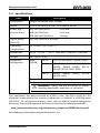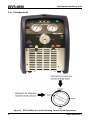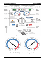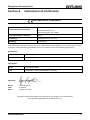
1
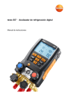
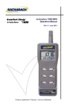
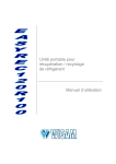
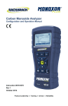
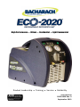
High Performance • Oilless • Residential • Light Commercial Product Leadership • Training • Service • Reliability User Manual 2020-9000 Rev. 0 September 2013 Refrigerant Recovery Unit WARRANTY Bacharach, Inc. (Bacharach) warrants to the buyer that this product will be free from material defects, free from manufacturing defects, and will conform substantially to Bacharach’s applicable specifications at the time of delivery. Bacharach’s liability and the buyer’s remedy under this warranty are limited to the repair or replacement, at Bacharach’s option, of this product or parts thereof returned with a Return Material Authorization (RMA) to Bacharach and shown to Bacharach’s reasonable satisfaction to have been defective; provided that written notice of the defect is given by buyer to Bacharach within one (1) year after the date of purchase of this Product from an authorized Bacharach distributor, as indicated on the original sales receipt. The warranty excludes damage to the unit caused by misuse or mishandling. Such abuse, as determined by Bacharach, will void the warranty, and the customer can decide to have the unit repaired at current repair rates, replaced at current cost, or returned (postage paid by customer). If you have any questions, please contact our Customer Service Department at 800-736-4666 or email them at [email protected]. Bacharach warrants to the buyer that Bacharach will convey good title to this product. Bacharach’s liability and the buyer’s remedy under this warranty of title are limited to: the removal of any title defects or, at the election of Bacharach, the replacement of this product or parts thereof that are defective in title. The foregoing warranty is exclusive and is given and accepted in lieu of (I) any and all other warranties, express or implied, including without limitation the implied warranties of merchantability and fitness for a particular purpose: and (II) any obligation, liability, right, claim or remedy in contract or tort, whether or not arising from Bacharach’s negligence, actual or implied. The remedies of the buyer shall be limited to those provided herein to the exclusion of any and all other remedies including, without limitation incidental or consequential damages. No agreement varying or extending the foregoing warranty, remedies or this limitation will be binding upon Bacharach unless in writing and signed by a duly authorized officer of Bacharach. Copyright © 2013, Bacharach, Inc. All rights reserved. BACHARACH is a registered trademark of Bacharach, Inc. ECO-2020 and the stylized ECO-2020 logo are trademarks of Bacharach, Inc. All other trademarks, trade names, service marks and logos referenced herein belong to their respective owners. 2 2020-9000 Rev 0 Refrigerant Recovery Unit Table of Contents SECTION 1. INTRODUCTION ......................................................................... 4 1.1. Safety (General Prerequisites) .................................................................. 4 1.2. Safety (Proper Surroundings) .................................................................... 5 1.3. Safety (Proper Setup) ................................................................................ 5 1.4. Safety (Proper Operations) ....................................................................... 6 1.5. Specifications ............................................................................................ 7 1.6. Components .............................................................................................. 8 SECTION 2. OPERATION ............................................................................. 12 2.1. Overview ................................................................................................. 12 2.2. High Pressure Shut-Off Feature............................................................... 13 2.3. Low Pressure Shut Off Feature................................................................ 13 2.4. 80% Shut-Off Feature .............................................................................. 13 2.5. Recovery Mode (Liquid or Vapor) ........................................................... 13 2.6. Purge Mode ............................................................................................. 16 2.7. Liquid Push/Pull Recovery Mode ............................................................ 16 2.8. Recovery Tips .......................................................................................... 19 2.9. Resuming an Interrupted Recovery ........................................................ 19 SECTION 3. MAINTENANCE AND TROUBLESHOOTING ............................... 20 3.1. Troubleshooting ...................................................................................... 20 3.2. Exploded Drawing Showing Spare Parts.................................................. 21 3.3. Accessories .............................................................................................. 23 3.4. Wiring Diagram ....................................................................................... 24 SECTION 4. DECLARATION OF CONFORMITY.............................................. 27 List of Figures Figure 1. ECO-2020 (Front View Showing Control Knob Operation)................. 8 Figure 2. ECO-2020 (Front Panel and Gauge Details) ....................................... 9 Figure 3. Shoulder Strap (Showing Connecting Points) .................................. 10 Figure 4. Filter and 4-Inch Hose ...................................................................... 10 Figure 5. Optional 80% Shut-off Cable ............................................................ 11 Figure 6. Power Connector, Example Power Cord, and Sample Power Labels ............................................................................................... 11 Figure 7. Recovery Configuration.................................................................... 15 Figure 8. Liquid Push/Pull Configuration ........................................................ 18 Figure 9. Parts Diagram ................................................................................... 21 Figure 10. Wiring Diagram ................................................................................ 24 2020-9000 Rev 0 3 Refrigerant Recovery Unit Section 1. Introduction 1.1. Safety (General Prerequisites) KNOW YOUR EQUIPMENT! Before operating this unit, please read this manual in its entirety. It is important that you have a thorough understanding of the procedures outlined in this manual. Failure to follow these procedures could void all manufacturer warranties. Also, read and understand the labels affixed to the unit. Learn the application and limitations as well as the specific potential hazards of your equipment. READ THE MSDS (material safety data sheet) from the refrigerant manufacturer before handling refrigerants. CAUTION! These instructions are for personnel trained and experienced in the handling of refrigerants. Unqualified individuals should not attempt to operate this equipment. Failure to follow proper operating procedures may cause personal injury. COMBUSTIBLE/FLAMMABLE GAS WARNING! For your safety, DO NOT use this device to recover refrigerants which are rated as combustible/flammable gases (e.g., ASHRAE - A2 or A3 rated refrigerants). CAUTION! Wear safety goggles and protective gloves. Avoid eye contact and prolonged skin exposure to liquid refrigerant, as contact may cause frostbite. CAUTION! Avoid breathing high concentrations of refrigerant vapors. Inhalation of high concentrations is harmful and may cause heart irregularities, unconsciousness, or death. 4 2020-9000 Rev 0 Refrigerant Recovery Unit 1.2. Safety (Proper Surroundings) AVOID DANGEROUS ENVIRONMENTS! Although the unit can be used outdoors, do not operate in the rain or in wet locations. Secure the unit when working above floor level. This equipment should not be used in the vicinity of spilled or open containers of flammable materials. HAZARDOUS AREA WARNING! This instrument has not been designed to be intrinsically safe for use in areas classified as hazardous locations. DO NOT use it in locations classified as hazardous. VENTILATION REQUIREMENTS! This equipment should be used in a location that is thoroughly ventilated (e.g., outdoors). For indoor use, mechanical ventilation must provide at least 4 air changes per hour, or the equipment should be located at least 18" above the floor. 1.3. Safety (Proper Setup) CAUTION! Make sure the power switch is in the OFF position before plugging this equipment into an AC power source. GROUND ALL EQUIPMENT! The ECO-2020 is equipped with a threepronged grounded power cord. USE AN APPROPRIATE EXTENSION CORD! Keep extension cord length 2 to a minimum. It should be a minimum of 14 AWG (2.0 mm ) and no longer than 25 feet (7.5 m) to minimize the possibility of damage to the compressor. CAUTION! All refrigerant hoses, recovery tanks, refrigerant lines, the ECO-2020 unit, and other vessels containing refrigerants should be handled at all times as if under high pressure. WARNING! Before starting the unit you MUST OPEN the port to the recovery tank. Failure to open the port will cause permanent damage to the ECO-2020 and void the warranty. 2020-9000 Rev 0 5 Refrigerant Recovery Unit 1.4. Safety (Proper Operations) WARNING! Only cylinders rated at 400 psi or greater and certified for R410A should be used to recover R410A. Failure to use the proper cylinder can be extremely dangerous. USE RECOMMENDED ACCESSORIES! Follow the instructions that accompany all accessories. Improper use of accessories may damage the equipment or create a hazard. USE WEIGHT (CHARGING) SCALE! When the ECO-2020 does not have the 80% Shut-Off Kit option installed, a scale (P/N 2010-0000 or similar) must be used to indicate when the recovery tank is 80% full (to prevent overfilling). WARNING! The input pressure of the ECO-2020 must not exceed 26 bars (337 psi). WARNING! The ECO-2020 must be positioned upright on a level surface, otherwise vibration, noise, and/or abrasion may occur. WARNING! Do not block the ventilation openings of the ECO-2020. WARNING! If the internal circuit breaker trips, wait at least 5 minutes before resetting. REPAIR DAMAGED PARTS! Do not operate the unit with a defective part. Repair unit to proper operating conditions. WARNING! Unplug unit before servicing; otherwise, an electrical shock hazard will be present when the unit is disassembled. IMPORTANT! Periodically check the filter screen (located inside the brass fitting of the inlet port) before using and clean if necessary. 6 2020-9000 Rev 0 Refrigerant Recovery Unit 1.5. Specifications Item Description Compressor Oilless, air-cooled, twin cylinder Motor 1 HP (1450 rpm @ 50 Hz; 1750 rpm @ 60 Hz) Power and Current Draw 110-120 VAC/60 Hz 100 VAC/50-60 Hz 220-240 VAC/50-60 Hz High Pressure Shut-Off 38.5 bar (3850 kPa, 558 psi) Operating Temperature 32° to 104° F (0° to 40° C) Dimensions 16.13″ × 10.25″ × 13.75″ (410 mm × 260 mm × 350 mm) Weight 28.5 lbs (12.9 kg) Supported Refrigerants AHRI 740-98 10 A max 10 A max 5A max Cat III: R12, R134A, R401C, R406A, R500 Cat IV: R22, R401A, R401B, R402B, R407C, R407D, R408A, R409A, R411A, R411B, R412A, R502, R509 Cat V: R402A, R404A, R407A, R407B, R410A, R507 Contact factory for other supported refrigerants. WARNING! Never use the ECO-2020 to pump anything flammable, explosive, or corrosive. This equipment has been certified by AHRI to meet the EPA's Clean Air Act minimum requirements for recovery equipment as defined in AHRI Standard 740-1998. For refrigerant recovery rates, refer to AHRI’s Certified Refrigerant Recovery/ Recycling Equipment Directory located at the following web URL. http://www.ahridirectory.org/ahridirectory/pages/rrr/RRREDirectory.pdf For additional information contact Bacharach, Inc. 2020-9000 Rev 0 7 Refrigerant Recovery Unit 1.6. Components Figure 1. ECO-2020 (Front View Showing Control Knob Operation) 8 2020-9000 Rev 0 Refrigerant Recovery Unit Figure 2. ECO-2020 (Front Panel and Gauge Details) 2020-9000 Rev 0 9 Refrigerant Recovery Unit Figure 3. Shoulder Strap (Showing Connecting Points) Figure 4. Filter and 4-Inch Hose 10 2020-9000 Rev 0 Refrigerant Recovery Unit Figure 5. Optional 80% Shut-off Cable Figure 6. Power Connector, Example Power Cord, and Sample Power Labels 2020-9000 Rev 0 11 Refrigerant Recovery Unit Section 2. Operation 2.1. Overview IMPORTANT: Do not mix different refrigerants together in one tank. IMPORTANT: Before recovering refrigerant, the recovery tank should achieve a vacuum level of 29.6 in Hg (75 cm Hg) to purge non-condensable gases. Tanks are typically filled with nitrogen when manufactured in the factory. This nitrogen must be evacuated before the first use. IMPORTANT: The power switch must be OFF before operation. IMPORTANT: A in-line filter should always be used and should be replaced frequently. Each type of refrigerant must have its own filter. For optimal results, use only Bacharach replacement filters. IMPORTANT: In order to gain maximum recovery speed, a hose with inner diameter larger than 3/16” (5 mm) is recommended and the hose should be shorter than 5’ (1.5 m). IMPORTANT: For recovering large amounts of liquid, use the Push/Pull configuration. IMPORTANT: After recovering, make sure there is no refrigerant left in the unit. Refer to the Purge Operation section. Liquid refrigerant remaining in the unit may expand and destroy components. IMPORTANT: If the unit is to be stored or remain unused for any length of time, completely evacuate any residual refrigerant and purge the unit with dry nitrogen. IMPORTANT: The intake port is equipped with a filter screen. Clean it before every use to maintain performance. NOTE: The low pressure gauge shows the pressure of the intake port of the compressor. The high pressure gauge shows the pressure of the outlet port of the recovery unit. 12 2020-9000 Rev 0 Refrigerant Recovery Unit IMPORTANT: After use, turn the knob to the OFF position (to close inlet/outlet valves). Input and output fittings should be covered with protective caps when the unit is not in operation. Moisture in the air is harmful to the recovery process and will shorten the lifespan of the unit. 2.2. High Pressure Shut-Off Feature The ECO-2020 has an internal high-pressure shut-off switch. If the pressure inside the system rises above the rated shut-off pressure (see specifications), the compressor will automatically shut off and the red high pressure alarm light will turn on. In the event the switch is activated, the output gauge should indicate < 435 psi (30 bars) to reset the switch. 2.3. Low Pressure Shut Off Feature The unit has an internal low-pressure shut-off switch. If the pressure inside the system is lower than -14 in Hg (-35.5 cm Hg) for approximately 20 seconds, the unit will automatically shut off and the green low-pressure alarm light turns on. 2.4. 80% Shut-Off Feature This unit can be used with a recovery tank’s float level sensor. Connect the recovery unit and the tank with the 80% shut-off cable. If the liquid refrigerant reaches 80% capacity of the tank, the recovery unit will automatically shut off and the red 80% shut-off alarm light turns on. Before restarting the compressor, be sure to install a new (empty) tank. IMPORTANT: If the refrigerant tank has no float level sensor, remove the 80% shut-off cable from the unit. Otherwise, the recovery unit will not start. 2.5. Recovery Mode (Liquid or Vapor) The ECO-2020 can be used for pumping virgin refrigerant on an intermittent basis. Unlike recovered refrigerant, virgin refrigerant does not contain oil. CAUTION: Routinely pumping virgin refrigerant through the ECO-2020 can remove lubrication from the compressor, resulting in premature failure. 2020-9000 Rev 0 13 Refrigerant Recovery Unit ATTENTION: Use an in-line filter when recovering liquid. Contaminants (particularly from the bottom of recovery cylinders) can enter the ECO2020 and become lodged in the valve seats causing damage and resulting in leaks. We recommend using Bacharach in-line filter P/N 2020-0001 for optimum recovery speed. IMPORTANT: Make all hose connections as shown in Figure 7. Ensure that all connections are correct and secure. IMPORTANT: Ensure all valves are CLOSED and ensure the filter screen is clean. Step Description (Recovery Mode – Liquid or Vapor) 1 Switch off power to the refrigerant equipment and connect power to the ECO-2020. 2 Turn the control knob to the START position. 3 Open the vapor and/or liquid valves of the refrigerant equipment. 4 Open the vapor valve of the recovery tank. 5 Turn on the power switch. 6 Press the start button. 7 Slowly turn the control knob to the RECOVER position. 8 When recovery is finished, the low pressure switch will activate, the motor will shut off, and the green “Complete” LED will come on. 9 Purge the unit (refer to section 2.6 on page 16). IMPORTANT: If compressor knocking occurs when the control knob is in the RECOVER position, slowly turn the control knob toward the START position until the knocking stops. 14 2020-9000 Rev 0 Figure 7. Recovery Configuration Refrigerant Recovery Unit 2020-9000 Rev 0 15 Refrigerant Recovery Unit 2.6. Purge Mode IMPORTANT: The unit must be purged after each use. Liquid refrigerant remaining in the unit may expand, damage the components, and pollute the environment. Step Description (Purge Mode) 1 Note that the unit stops automatically after recovery is complete. 2 Turn the control knob to the PURGE position. The motor will automatically restart. When purging is finished, the low pressure switch will activate, the motor will shut off, and the green “Complete” LED will come on. 3 Turn off the power switch. 4 Close the valves of the hoses, recovery tank, etc. 5 Disconnect all hoses. 6 Turn the control knob to the OFF position. 2.7. Liquid Push/Pull Recovery Mode If any of the following conditions are true in the system being evacuated, the liquid push-pull method may not be practical and a normal liquid/vapor recovery should be performed. • • • • • The equipment contains less than 20 lbs (9.1 kg) of refrigerant. The equipment is a heat pump or other system with refrigerant flow that would prevent you from isolating the liquid. Equipment has an accumulator between the service ports used in the liquid recovery process. Liquid refrigerant migration has occurred and the location of the liquid is unknown. The refrigerant tubing design on the equipment does not allow for a solid column of liquid refrigerant to be formed. IMPORTANT: If the 80% shut-off cord is not used, then use a scale (P/N 2010-0000) to monitor the refrigerant level in the recovery cylinder in order to prevent overfilling. IMPORTANT: Ensure all valves are CLOSED. 16 2020-9000 Rev 0 Refrigerant Recovery Unit IMPORTANT: Make all hose connections as shown in Figure 8. Ensure that all connections are correct and secure. Step Description (Liquid Push/Pull Recovery Mode) 1 Switch off power to the refrigerant equipment and connect power to the ECO-2020. 2 Turn the control knob to the START position. 3 Open the vapor and liquid valves of the refrigerant equipment. 4 Open the vapor and liquid valves of the recovery tank. 5 Turn on the power switch. 6 Press the start button. 7 Slowly turn the control knob to the RECOVER position. 8 Turn the control knob to the PURGE position. (Refer to Purge Mode in section 2.6 on page 16.) 9 Turn off the power switch after purging is complete. 10 Close the vapor and liquid valves of the refrigerant equipment. 11 Close the vapor and liquid valves of the recovery tank. 12 Turn the control knob to the OFF position. 13 Connect the hoses again according to the Recovery Mode section 2.5 on page 13 and recover the vapor from the refrigerant equipment. IMPORTANT: A scale or liquid-sight glass can be used to determine when all the liquid is recovered. The ECO-2020 will not pull a vacuum using the liquid push-pull recovery operation. To finish the recovery operation, you must perform vapor recovery operations as described on page 13. IMPORTANT: When the scale reading remains unchanged or changes very slowly, the liquid recovery portion of push/pull mode is finished, and you are ready to perform the vapor recovery portion. WARNING: If the scale shows that the refrigerant tank reaches 80% capacity, turn off power and close the valves of the tank. Replace the full tank with an empty tank (under vacuum) and resume where you left off. 2020-9000 Rev 0 17 Figure 8. Liquid Push/Pull Configuration Refrigerant Recovery Unit 18 2020-9000 Rev 0 Refrigerant Recovery Unit 2.8. Recovery Tips • • • • • • • • Use the shortest hoses possible. Long hoses increase the recovery time. Remove all restrictions in the hoses. Hoses with ball valves at the ends are better than hoses that are self-sealing. When possible, temporarily remove Shrader core valves (if used) from the service ports prior to the recovery process, as these valves significantly restrict recovery flow and extend recovery time. Be sure to use a Shrader core remover/installer tool (designed for use in pressurized systems) to prevent the illegal loss of refrigerant into the atmosphere. Always identify the refrigerant you are recovering. This will minimize cross contamination and help you plan for the amount of refrigerant you will be recovering. Pump liquid out of the system first, and then recover the remaining vapors. This will significantly speed up recovery rates. With large amounts of refrigerant, use the liquid push-pull recovery method. This method is faster than recovering liquid directly. Refer to the liquid push-pull instructions. When possible, recover from both the high and low side service ports on the refrigeration system. This will speed up the recovery rate. Use an in-line filter (P/N 2020-0001) to prevent contaminants from entering the ECO-2020. The use of connection hoses with ball valves can help to minimize refrigerant loss. NOTE: Using a manifold gauge set is not required. 2.9. Resuming an Interrupted Recovery Step Description (Resuming an Interrupted Recovery) 1 Resolve the issue that caused the interruption (e.g., breaker, high pressure switch, loss of power, etc.). 2 Turn the control knob to the START position. 3 Press the START button. 4 Slowly rotate the control knob to the RECOVERY position to resume recovery. 2020-9000 Rev 0 19 Refrigerant Recovery Unit Section 3. Maintenance and Troubleshooting 3.1. Troubleshooting Fault Compressor won’t start Possible Cause(s) Solution(s) High pressure shut off (Red alarm light) Lower pressure below 435 psi (30 bars) Motor failure or other component damage. Replace the components. Factory service is required. 80% shut-off cable is connected to unit, but not to recovery cylinder Connect to recovery cylinder or remove from unit. Recovery tank pressure is too high. Cooling down the tank can help to reduce the pressure. The piston ring of the compressor is damaged. Replace components. Dirty in-line filter or inlet filter screen Clean/replace inlet filter screen. Replace in-line filter. Unit doesn’t pull a vacuum Loose hoses. Tighten the hose connections. Leakage in the unit. Replace components. Compressor starts, but stops within a few moments High pressure shut off due to wrong operation, such as outlet valve not open, or recovery tank valve not open. Carefully review the operation manual and follow the instructions while operating. Motor thermal protector shuts off. Compressor will restart automatically. Circuit breaker shuts off. Wait 5 minutes, reset the circuit breaker, then restart. 80% shut-off protection (red alarm light on). Replace full recovery tank with an empty recovery tank. Recovery is complete. Unit is under low pressure protection (green alarm light on). Refer to the purge section. Low recovery speed 20 Factory service is required. Factory service is required. 2020-9000 Rev 0 Refrigerant Recovery Unit Figure 9. Parts Diagram 3.2. Exploded Drawing Showing Spare Parts 2020-9000 Rev 0 21 Refrigerant Recovery Unit Part Number Dwg Item # Spare Part Description 0304-3461 Power supply cord, CEE 7/7 0304-3462 Power supply cord, SANS 164-1 0304-3467 1 Power supply cord, AS 3112 0304-3468 Power supply cord, NEMA 5-15 3015-5636 Power supply cord, BS 1363 2020-0001 31 In-line filter 2020-0002 32 Hose (4” long, 3/16” I.D.) 2020-0004 2 80% Shut-off cord 2020-0005 30 Shoulder strap 2020-0006 3 Filter screen for inlet fitting 2020-0007 4 Inlet fitting O-ring 2020-0008 29 Inlet fitting 2020-0010 5 Control knob 2020-0011 2020-0037 2020-0012 6 Circuit breaker; 110 V Circuit breaker; 220 V 7 Gauge (input) 2020-0013 8 Gauge (output) 2020-0014 10 Switch (push-button, start) 2020-0015 11 Manifold assembly 2020-0016 12 O-ring, 67 x 2.65 mm (I.D. x wall thickness) 2020-0017 2020-0039 2020-0018 2020-0019 2020-0040 13 14 15 Capacitor (running); 110 V Capacitor (running); 220 V Circuit board (main) Capacitor (starting); 110 V Capacitor (starting); 220 V 2020-0020 16 O-ring, 2.8 x 1.8 mm (I.D. x wall thickness) 2020-0021 17 O-ring, 30 x 1.8 mm (I.D. x wall thickness) 2020-0022 18 Piston ring 2020-0023 19 Piston ring retaining plate 2020-0024 20 Screw, M5 x 14, stainless steel 2020-0025 21 Cylinder 2020-0026 22 Pin, 30 x 1.8 mm 22 2020-9000 Rev 0 Refrigerant Recovery Unit Part Number Dwg Item # 2020-0027 23 Valve plate assembly 2020-0028 24 O-ring, 10.8 x 1.8 mm (I.D. x wall thickness) 2020-0029 25 Exhaust valve 2020-0030 26 Exhaust valve spring 2020-0031 27 O-ring, 32.5 x 1.8 mm (I.D. x wall thickness) 2020-0032 28 Cylinder cover assembly 2020-0033 2020-0034 2020-0035 2020-0038 2020-9000 not shown 33 9 34 Spare Part Description Set of enclosure screws (Qty. 13 screws and washers, 3 flange nuts for handle, 1 pin for shoulder strap) Set of rubber feet with screws Switch (rocker, power); 110 V Switch (rocker, power); 220 V Instruction manual 3.3. Accessories Part Number Accessory Description 2002-0003 R12/22/134A ball valve hose set 2002-0040 R410A ball valve hose set 2002-1340 R134A low side coupler (blue) 2002-1341 R134A high side coupler (red) 2002-4000 R12/22/134A manifold set with sight glass 2002-4300 R410A manifold set with sight glass 2002-4400 R410A manifold set 2002-4600 R410A hose set 2002-4700 R12/22/134A hose set 2002-5000 R12/22/134A manifold set 2010-0000 Charging scale 2020-9000 Rev 0 23 Refrigerant Recovery Unit Figure 10. Wiring Diagram 3.4. Wiring Diagram 24 2020-9000 Rev 0 Refrigerant Recovery Unit Code Component Code Components XS Power Outlet LP Low Pressure Switch PS Power Switch OFP 80% Shut-Off Switch FR Overload Protection Device D1 Red LED (High Pressure) M1 Compressor Motor D3 Red LED (Shut-Off) SR Centrifugal Switch D2 Green LED C1 Start Capacitor D4 Power LED C2 Running Capacitor SB Start Button ST Motor Thermal Protectors CTR Control Module TC Electronic Transformer K1 Relay HP High Pressure Switch 2020-9000 Rev 0 25 Refrigerant Recovery Unit 26 2020-9000 Rev 0 Refrigerant Recovery Unit Section 4. Declaration of Conformity DECLARATION OF CONFORMITY The manufacturer of the products covered by this declaration: Bacharach, Inc. 621 Hunt Valley Circle New Kensington, PA 15068 Year conformity is declared: 2013 Product(s): Refrigerant Recovery Unit Model(s): ECO-2020 The undersigned hereby declares that the above referenced products are in conformity with the provisions of the following standard(s) and is in accordance with the following directive(s). Directive(s): 2004/108/EC Electromagnetic Compatibility 2006/95/EC Low Voltage Directive Standard(s): EMC EN 55014-1:2006 LVD EN 60335-1:2002 and EN 60335-2-34:2002 Signature: Name: Title: Date: Doug Keeports President August 26, 2013 The technical documentation file required by this directive is maintained at the corporate headquarters of Bacharach, Inc. 2020-9000 Rev 0 27 Refrigerant Recovery Unit World Headquarters 621 Hunt Valley Circle, New Kensington, Pennsylvania 15068 Phone: 724-334-5000 • Toll Free: 1-800-736-4666 • Fax: 724-334-5001 Website: www.MyBacharach.com • E-mail: [email protected] 28 2020-9000 Rev 0