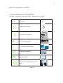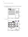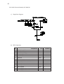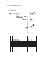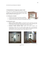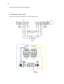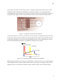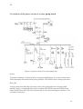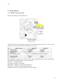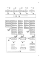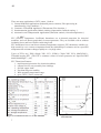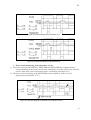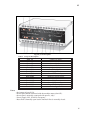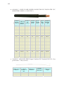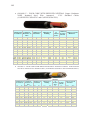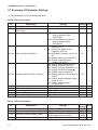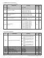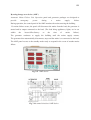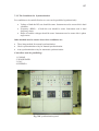
1
The Islamic University of Gaza, Electrical Engineering Department 2009-2010 1 Fall semester Electrical Boards (EELE 5421) Course outline By Prof. Dr. Muhammed Abdelati Week Chapter 1Ͳ2 1.Electrical subscription Subject 1.1IntroductiontoElectricalsubscriptionratingsandboards(singleline, Layout,BillofQuantity(BOQ)) 1.2HouseͲusesubscriptions o Oneusersinglephase o Oneuser3phase o SmallBuildingcomprises6singlephase&one3phasesubscriptions o Towerbuildingcomprises44singlephase&one3phasesubscriptions 1.3Industrialsubscriptions o 100Ͳ400Asubscriptions o 630Ͳ1600Asubscriptions o 2000Ͳ2600Asubscriptions 1.4Changeoverpowercircuit 1.5Activeandreactivepowermetersillegaltricks 1.6Indicatorsandmeters 1.7Powerfactorcorrection 1.8Transformersratingsandwiringconnections 3 2.Introductionto 2.1AutoCADtutorial AutoCad 2.2Electricalsymbols(installationsdiagrams,electricalcircuits) 2.3InternationalProtection(IP)rating 4Ͳ5 3.Softstartingof 3.1Standardwiring threephasemotors 3.2Directioncontrol usingRVSͲDN 3.3InsideDeltaconnection 3.4Powerfactorcorrectingcapacitorconnection 3.5Analysisofthepowercircuitofawaterpumpboard 3.6Programming 6Ͳ7 4.Pumpcontrol 4.1Temperaturesensors 1. Thermocouples x J x K x S 2. ResistiveTemperatureDevices(RTD) x PRTs ¾ PT100 ¾ PT1000 x Ni 3. Thermistors x PTC x NTC 4. Semiconductortemperaturesensors 4.2OverloadMonitoringrelay(EMT6) 4.3Pumpcontrolandstatusmodules(FlygetCAS) 4.4Controlcircuitofawaterpumpboard 8 Review&1st Midterm 9 5.ElectricalCables 5.1Cablestandards x DINVDE0281/0282 x DINVDE0271/0272/0273/0276 5.2Cableselectioncriteria 10Ͳ11 6.Speedcontrolof3 6.1circuitdiagram phasemotorsusing 6.2programmingthroughinterfacebuttons VFD 6.3programmingthroughPC. 6.4RS485protocolinterface 12 7.Generatorsboards Changeovercontrolcircuit GeneratorSynchronizingboards 13Ͳ14 8.SelectedProjects 8.1Waterpumpstation 8.2SoftdrinkFactory 8.3Wastewaterpumpstation 15 Review&2ed Midterm 2 EELE5421ElectricalBoards,Fall2009/10 TheIslamicUniversityOfGaza EngineeringFaculty ElectricalDepartment : ΐϟΎτϟ 120060831 ϱϭΎϤϳήϟ ϝΎϤΟ ΪϤΤϣ : ϑήη· ϲσΎόϟ ΪΒϋ ΪϤΤϣ / Ω. 2009/ήΒϤδϳΩ 3 EELE5421ElectricalBoards,Fall2009/10 CHAPTER1 IntroductiontoElectricalsubscriptionratings Introductiontochangeoverpowercircuit. Activeandreactivepowermetersillegaltricks Indicatorsandmeters Power factor correction Transformersratingsandwiringconnections 4 EELE5421ElectricalBoards,Fall2009/10 TableofContents 1.1 IntroductiontoElectricalsubscriptionratings…………………………………………. 1.1.1.Subscriptionstypesdependingonelectricaluse………………………………………………………… 1.1.2.Subscriptionsareeither3phaseorbeonephase……………………………………………….. 1.1.3.somecomponentsusedinelectricalboards. 1.2 houseͲusesubscriptions……………………………………………………………………………. 1.2.1.oneusersinglephase…………………………………………………………………………………………. 1.2.2.oneuser3Ͳphase. 1.2.3.Smallbuildingcomprises6singlephase&one3Ͳphasesubscriptions……………… 1.2.4.Towerbuildingcomprises44singlephase&one3Ͳphasesubscriptions……………… 1.3industrialsubscriptions………………………………………………………………………. 1.100Ͳ400Asubscriptions……………………………………………………………………………………………. 2.630Ͳ1600Asubscriptions…………………………………………………………………………………………. 3.2000Ͳ2600Asubscriptions.……………………………………………………………………………………… 1.4Introductiontochangeoverpowercircuit………………………………………………… 1.4.1ChangeOverclassified………………………………………………………………………………………… 1.4.2ChangeOvertypes……………………………………………………………………………………………… 1.4.3ChangeOverpowercircuit………………………………………………………………………………….. 1.5Activeandreactivepowermetersillegaltricks…………………………………………. 1.5.1Electromechanicaltechnology…………………………………………………………………………….. 1.5.2ActiveandReactivePowerMetersIllegalTricks………………………………………………….. 1.6Indicatorsandmeters……………………………………………………………………………… 1.6.1panelmeterstypes……………………………………………………………………………………………. 1.6.2 Exampleofdigitalpanelmeter………………………………………………………………………….. 5 EELE5421ElectricalBoards,Fall2009/10 1.7Powerfactorcorrection.……………………………………………………………………… 1.7.1ActivePower……………………………………………………………………………………………………… 1.7.2PowerFactor……………………………………………………………………………………………………… 1.7.3ADVANTAGESCOMPAREDTOCAPACITORBANK………………………………………………. 1.7.4improvingpowerfactor……………………………………………………………………………………. 1.7.5connectionofcapacitorbank…………………………………………………………………………….. 1.8Transformersratingsandwiringconnections………………………………………….. 1.8.2PowerTransformerRating………………………………………………………………………………… 1.8.1partsinthedistributiontransformer…………………………………………………………………… Reference………………………………………………………………………………………………… 6 EELE5421ElectricalBoards,Fall2009/10 1.1 IntroductiontoElectricalsubscriptionratings. Theelectricitydistributioncompaniesdistributeelectricitytoconsumersinaccordancewith aparticularsystemsothattheycanbereconciledbetweenthepowerdistributionnetwork and consumer demand in general subscriptions divided into two kinds the household subscriptionsͲlowpowerͲandtheindustrialsubscriptionsͲhighͲpowerͲ,thepricerequiredfromthe consumerisaccordancewiththeseRegulations. 1.1.1.Subscriptionstypesdependingonelectricaluse:isdividedasfollows: x x x x commercial industrial agriculture services 1.1.2.Subscriptionsareeither3phaseorbeonephase:whichaccordingtothefollowing: Ȍ ǣ x 1Ͳphase40A x 3Ͳphase30A x 3Ͳphase63A Ȍ ǣ x 3Ͳphase30A x 3Ͳphase63A x 3Ͳphase100A x 3Ͳphase160A x 3Ͳphase200A x 3Ͳphase250A x 3Ͳphase300A x 3Ͳphase400A x 3Ͳphase600A x 3Ͳphase1000A x 3Ͳphase1600A x 3Ͳphase2000A x 3Ͳphase2500A 7 EELE5421ElectricalBoards,Fall2009/10 1.1.3.somecomponentsusedinelectricalboards. TheTable1.1shownthecomponentpicture,description&itissymbol. Symbol Picture Description 1ͲPHASECIRCUITBreaker. 3ͲPHASECIRCUITBREAKER. 220V/24VSIGNALLAMP. XX/5ACURRENTTRANSFORMER. 5AANALOGUEAMMETER. 400VVOLTMETER.. SEVENSTAGESINSTRUMENTSELECTOR SWITCH. Table1.1 8 EELE5421ElectricalBoards,Fall2009/10 1.2 houseͲusesubscriptions. 1.2.1.oneusersinglephase. Ȍ Ǥ x Size45X60X20CM EO EO EO EO Ȍ Ǥ EO %$:# EO T EO EO 9 EELE5421ElectricalBoards,Fall2009/10 Ȍ Ǥ Ȍ Ǥ No. 1. 2. 3. 4. 5. 6. Component C.B2x32A R.C.D2X40A C.B16A KWH1Ͳphase CABLE(CU)2x(6Ͳ10)mm2 CABLE(CU)1x6mm2 unit piece piece piece piece meter meter Quantity 1 1 8 1 30 20 10 EELE5421ElectricalBoards,Fall2009/10 1.2.1.oneuser3Ͳphase. Ȍ Ǥ x Size60X80X20CM 4 5 6 EO EO EO EO Ȍ Ǥ %$:# %$:# EO T EO %$:# EO EO 11 EELE5421ElectricalBoards,Fall2009/10 Ȍ Ǥ Ȍ Ǥ No. 1. 2. 3. 4. 5. 6. 7. 8. 9. Component C.B4x32AOR64A R.C.D4X40A C.B16A C.B6A SIGNALLAMP CAPACITORBANK10KVAR KWH1Ͳphase CABLE(CU)4x(6Ͳ10)mm2 CABLE(CU)1x6mm2 unit piece piece piece piece piece piece piece meter meter Quantity 1 1 10 1 3 1 1 30 20 12 EELE5421ElectricalBoards,Fall2009/10 1.2.3.Smallbuildingcomprises6singlephase&one3Ͳphasesubscriptions Ȍ Ǥ 4 200 L1-L2 L1-L3 L2-L3 200 0 5 6 200 L1-N L1-N L1-N EO EO EO EO Ȍ Ǥ EO EO ECRCEKVQTDCPM EO EO 13 EELE5421ElectricalBoards,Fall2009/10 Ȍ Ǥ Ȍ Ǥ No. 1. 2. 3. 4. 5. 6. 7. 8. 9. 10. 11. 12. 13. Component NZM160A R.C.D4X40A SELECTORSWITCH FREQUANCYMETER VOLTMETER C.B16A C.B10A SIGNALLAMP CAPACITORBANK10KVAR KWH1Ͳphase KWH3Ͳphase CABLE(CU)4x70mm2 CABLE(CU)1x25mm2 unit piece piece piece piece piece piece piece piece piece piece piece meter meter Quantity 1 6 1 1 3 1 1 3 1 6 1 200 150 14 EELE5421ElectricalBoards,Fall2009/10 1.2.4.Towerbuildingcomprises44singlephase&one3Ͳphasesubscriptions. Ȍ Ǥ x Size210X260X20CM 5 4 200 0 200 L1-N L1-N L1-N 60 210 150 L1-L2 L1-L3 L2-L3 6 200 100 80 80 15 EELE5421ElectricalBoards,Fall2009/10 ȌǤ 210 150 60 %$:# ECRCEKVQTDCPM 100 80 80 16 EELE5421ElectricalBoards,Fall2009/10 ȌǤ ȌǤ No. 1. 2. 3. 4. 5. 6. 7. 8. 9. 10. 11. 12. 13. Component NZM400A R.C.D4X40A SELECTORSWITCH FREQUANCYMETER VOLTMETER C.B16A C.B10A SIGNALLAMP CAPACITORBANK10KVAR KWH1Ͳphase KWH3Ͳphase CABLE(CU)4x135 mm2 CABLE(CU)1x70 mm2 unit piece piece piece piece piece piece piece piece piece piece piece meter meter Quantity 1 44 1 1 3 1 1 3 1 44 1 200 150 17 EELE5421ElectricalBoards,Fall2009/10 1.3industrialsubscriptions. 1.3.1.100Ͳ400Asubscriptions Ȍ Ǥ EO 5 4 200 L1-L2 L1-L3 L2-L3 0 6 200 200 L1-N L1-N EO EO EO Ȍ Ǥ EO EO EO EO EO ECRCEKVQTDCPM EO EO Front layer EO EO back layer 18 EELE5421ElectricalBoards,Fall2009/10 Ȍ Ǥ Ȍ Ǥ No. 1. 2. 3. 4. 5. 6. 7. 8. 9. 10. 11. 12. 13. 14. Component NZM100Ͳ400A LTL100Ͳ400A SELECTORSWITCH FREQUANCYMETER VOLTMETER C.B16A C.B10A SIGNALLAMP CAPACITORBANK10KVAR KWH1Ͳphase KWH3Ͳphase Kvar3Ͳphase CABLE(CU)4x35mm2 CABLE(CU)1x70mm2 unit piece piece piece piece piece piece piece piece piece piece piece piece meter meter Quantity 1 1 1 1 3 1 1 3 1 3 1 1 200 150 19 EELE5421ElectricalBoards,Fall2009/10 1.3.2.630Ͳ1600Asubscriptions. Ȍ Ǥ EO 5 4 200 L1-L2 L1-L3 L2-L3 0 6 200 200 L1-N L1-N EO EO EO EO EO Ȍ Ǥ EO EO EO ECRCEKVQTDCPM EO EO EO 20 EELE5421ElectricalBoards,Fall2009/10 Ȍ Ǥ Ȍ Ǥ No. 1. 2. 3. 4. 5. 6. 7. 8. 9. 10. 11. 12. 13. 14. Component NZM630Ͳ1600A LTL100Ͳ630A SELECTORSWITCH FREQUANCYMETER VOLTMETER C.B16A C.B10A SIGNALLAMP CAPACITORBANK10KVAR KWH1Ͳphase KWH3Ͳphase Kvar3Ͳphase CABLE(CU)4x60mm2 CABLE(CU)1x90mm2 unit piece piece piece piece piece piece piece piece piece piece piece piece meter meter Quantity 1 1 1 1 3 1 1 3 1 3 1 1 200 150 21 EELE5421ElectricalBoards,Fall2009/10 1.3.3.2000Ͳ2600Asubscriptions. Ȍ Ǥ EO 5 4 200 L1-L2 L1-L3 L2-L3 0 6 200 200 L1-N L1-N EO EO EO EO EO ȌǤ EO EO EO ECRCEKVQTDCPM EO EO EO 22 EELE5421ElectricalBoards,Fall2009/10 ȌǤ TO LOAD ȌǤ No. 1. 2. 3. 4. 5. 6. 7. 8. 9. 10. 11. 12. 13. 14. Component IZM 2000Ͳ2600A LTL100Ͳ2000A SELECTORSWITCH FREQUANCYMETER VOLTMETER C.B16A C.B10A SIGNALLAMP CAPACITORBANK10KVAR KWH1Ͳphase KWH3Ͳphase Kvar3Ͳphase CABLE(CU)4x80 mm2 CABLE(CU)1x90mm2 unit piece piece piece piece piece piece piece piece piece piece piece piece meter meter Quantity 1 1 1 1 3 1 1 3 1 3 1 1 200 150 23 EELE5421ElectricalBoards,Fall2009/10 1.4Introductiontochangeoverpowercircuit. One of the most commonly used circuit in power networks is change over switch circuit which transfer the power flow from the main power source to the stand by source which may be generator set look at figure 1.4. 1.4.1ChangeOverclassified: x x x Ǥ TransferSwitchbetweenUtilityandanotherutility. Ǥ 1.4.2ChangeOvertypes: x x Manual Transfer Switches (MTS): are generally the least expensive and least complicatedofthetwotypesoftransferswitches.MTS’srequiresomeonetobe onͲsitetostartandshutdownthegeneratorlookatfigure1.4.2(a). Automatic Transfer Switches (ATS): monitor the power supplies and automatically switch from the normal (utility) supply over to the generator suppliedpowersourceintheeventofapoweroutage.ATSequipmentcanhave manydifferentcontrolandalarmfeatureslookatfigure1.4.2(b). ab figure1.4.2 24 EELE5421ElectricalBoards,Fall2009/10 1.4.3ChangeOverpowercircuit: ThatistheschematicofpowercircuitofATSchangeover. 25 EELE5421ElectricalBoards,Fall2009/10 1.5Activeandreactivepowermetersillegaltricks. Modernelectricitymetersoperatebycontinuouslymeasuringthe instantaneous voltage (volts) and current (amperes) and finding the product of these to give instantaneous electrical power (watts)whichisthenintegratedagainsttimetogiveenergyused (joules, kilowattͲhours etc). The meters fall into two basic categories, electromechanical and electronic,The most common type of electricity meter is the Thomson or electromechanical inductionwattͲhourmeter,inventedbyElihuThomsonin1888. 1.5.1Electromechanicaltechnology The electromechanical induction meter operates by counting the revolutions of an aluminium disc which is made to rotate at a speed proportional to the power. The number of revolutions is thus proportional to the energy usage. It consumes a small amountofpower,typicallyaround2watts. Themetallicdiscisacteduponbytwocoils.Onecoilisconnectedinsuchawaythatit produces a magnetic flux in proportion to the voltage and the other produces a magneticfluxinproportiontothecurrent.Thefieldofthevoltagecoilisdelayedby90 degreesusingalagcoil.Thisproduceseddycurrentsinthediscandtheeffectissuch that a force is exerted on the disc in proportion to the product of the instantaneous currentandvoltage.Apermanentmagnetexertsanopposingforceproportionaltothe speed of rotation of the disc. The equilibrium between these two opposing forces results in the disc rotating at a speed proportional to the power being used. The disc drives a register mechanism which integrates the speed of the disc over time by counting revolutions, much like the odometer in a car, in order to render a measurementofthetotalenergyusedoveraperiodoftime. In practical electricity meter divided for two kind watch meter and load meter,connectiondiagramaredifferentandexplaineinfigure1&figure2. Figure1:watchmeterconnection 26 EELE5421ElectricalBoards,Fall2009/10 Figure2:watchmeterconnection 1.5.2ActiveandReactivePowerMetersIllegalTricks: 1Ͳ Inthe3ͲphaseKWhmeterthereisanillegaltrickthatis,ifwechangeonephase inputonlybyanoutputphase,then,therotatingrodwillrotateinaveryslow speedlookatFigure1.5.2a. 2Ͳ If we decline the KWh meter by a specified angle, then ,the rotating rod will notrotate. 3Ͳ For the KWh meters in which the rotating rod is made of metal, then , the rotatingrodwillstopifweputamagnetbesideit. 4Ͳ Inthe1ͲphaseKWhmeterthereisanillegaltrickthatis,ifweinterchangethe input phase & Neutral by output phase & Neutral, then, the rotating rod will rotateinareversemanner. Figure1.5.2aFigure1.5.2b 27 EELE5421ElectricalBoards,Fall2009/10 5Ͳ WecanmakeachangeoverswitchbetweenoutputandtheinputtotheKWh meterlookatFigure1.5.2c. Figure1.5.2c 6Ͳ Wecanconnectajunctionbetweentheneutralinputandneutraloutputinthe KWhmeterlookatFigure1.5.2c. Figure1.5.2d 7Ͳ EnterLandNcablebutattheoutputonlytakeLcabletakeNfromGroundas shownFigure1.5.2e. Figure1.5.2e. 28 EELE5421ElectricalBoards,Fall2009/10 1.6Indicatorsandmeters. A panel meter is an instrument that displays an input signal for AC & DC output and input distribution circuit, power plant console cabinet, power operating board and different apparatus. It is used to measure DC current, voltage & AC current, voltage, frequencyandphasepower. 1.6.1panelmeterstypes: x x Digitalpanelmetersasshowninfigure1.6.1a. Analogpanelmetersasshowninfigure1.6.1b. Figure 1.6.1 b. Figure 1.6.1 a. 29 EELE5421ElectricalBoards,Fall2009/10 1.6.2 Exampleofdigitalpanelmeter: KMM01Udigitalmultimeter KMM01Uisveryadvancedmultimeterwhichgivesuserprecisereadingsin4digitsand separateCTratioadjustmentsforflexiblesystems.Itisnotonlymeasures thecurrent pulledfromtheL1,L2,L3butalsovoltageandfrequencyofthoselinesinTrueRMS.All measured values are displayed in 5 rows, 3 rows for 3 ampere meter, one for the voltagethatiscyclingevery3seconds(VL1,VL2,VL3,VL1ͲL2,VL1ͲL3,VL2ͲL3)andone forthefrequencyofthelinevoltmetershows(betweenphasesshowsthefirstphase’s frequency). Figure1.4:digitalmultimeterconnectiondiagram 30 EELE5421ElectricalBoards,Fall2009/10 1.7Power factor correction. 1.7.1 Active Power: Pure resistive loads convert the Electrical Power to another form viz., Heat, Light or Mechanical Power. For, these type of loads which have no Inductiveorcapacitivecomponents,the voltage and current waveform intersect the “Zero” coͲordinate at the same point. ForsuchResistiveloads,thevoltageand current are set to be “InͲPhase”. The active Power “P” is calculated as the Product of momentary voltage and currentwitha“P”frequencydoubletothatof voltagesupplyanditisentirelyonthe positivearea.Withtheresistiveorohmicloads,“P”poweriscalculatedbymultiplying themomentaryvaluesofVoltageandCurrentP=v(t)xi(t)asshowninfigure1.7.1a. In practice, it is unusual to find purely resistive loads, since most of the electrical equipments has Inductive components and they operate in the presence of magnetic field like Motor, Transformer etc. The currentwhichisusedtocreateandreverse the magnetic field is not dissipated, but flows to and fro as Reactive Current between the Source and the Load. As illustrated in the figure1.7.1 b, the voltage and current waveform no longer intersect the “Zero” CoͲordinate at the same point, but with the displacement normally referred as displacement angle. With magnetic / inductive loads, the current lags the voltagewhereaswiththecapacitiveloadsthecurrentleadsthevoltageandthepower willbeP=V*I*Cosß. 31 EELE5421ElectricalBoards,Fall2009/10 1.7.2PowerFactor: ThecosineofangleofPhasedisplacementbetweenvoltageandcurrentinana.ccircuit isknownasPowerFactor.TheReactivecomponentisameasureofthePowerFactor.If theReactivecomponentissmall,thePhaseangleͲissmallandhencethePowerFactor CosǛwillbehigh. Therefore,acircuithavingsmallreactivecurrentwillhavehighPowerFactor ThePowerFactoratfullloadisnormally givenonthenameplatesoftheelectrical machines. As the Power distribution system must be dimensioned to carry theapparentpower,effortsaremadeto keep this as low as possible. If a device taking leading reactive power (e.g. capacitor) is connected in parallel with theload,laggingreactivepoweroftheloadwillbepartlyneutralizedthusimprovingthe PowerFactoroftheloadThereactivepowerQccorrectedbythecapacitorisgivenby the difference between the Inductive Reactive Power Q1 before correction and the reactivepowerQ2aftercorrectioni.e.Qc=Q1–Q2. 1.7.3ADVANTAGESCOMPAREDTOCAPACITORBANK 1. Low cost. 2. Stabilizing power. 3. Reduce cost of maintenance and servicing. 4. Prolong the life span of electrical appliances and fixed asset. 5. Prolong the Main Capacitor Bank. 6. Long Life Span. 7. Low risk and easy to maintain. 8. STAR Connection. 32 EELE5421ElectricalBoards,Fall2009/10 1.7.4improvingpowerfactor: Wecanimprovethepowerfactorfrom the following formula: for example : 1.7.5connectionofcapacitorbank: 1.DirectSystem:Suitforpremisesusebysmallpowerconsumer(SPC)thatfacing the low power factor problem. It can be used from a small percentage of power factorsinasmallampsusageuntilthehighestpercentageofpowerfactorinahigh ampsusageasshowninfigure1.7.5a. figure1.7.5a 33 EELE5421ElectricalBoards,Fall2009/10 2. Jointly Control System: Suit for Large Power Consumer (LPC) such as factory, shopping complex, large institution, hospital etc that using the capacitor banks as showninfigure1.7.5b. figure1.7.5a 34 EELE5421ElectricalBoards,Fall2009/10 1.8Transformers ratings and wiring connections Distribution transformer is used to convert electrical energy of higher voltage (usually 11Ͳ22Ͳ33kV)toalowervoltage(250or433V)withfrequencyidenticalbeforeandafter the transformation. Application of it is mainly within suburban areas, public supply authorities and industrial customers. With given secondary voltage, distribution transformerisusuallythelastinthechainofelectricalenergysupplytohouseholdsand industrialenterprises. 1.8.1partsinthedistributiontransformer: 1. Coils/winding – where incoming alternate current (through primary winding) generatesmagneticflux,whichinturndevelopamagneticfieldfeedingbacka secondarywinding. 2. Magnetic core – allowing transfer of magnetic field generated by primary windingtosecondarywindingbyprincipleofmagneticinduction 3. Tank – serving as a mechanical package to protect active parts, as a holding vessel for transformer oil used for cooling and insulation and bushing (plus auxiliaryequipmentwhereapplicable First2partsareknownasactiveparts. 35 EELE5421ElectricalBoards,Fall2009/10 1.8.2PowerTransformerRating: Tr.Rating(KVA) 50 100 160 250 400 630 800 1000 1250 1600 2000 FuseRating(A) 10 10 15 15 25 35 40 40 63 63 63 x Air transformer x ground transformer Instillation Outdoor Outdoor Outdoor Outdoor Outdoor&indoor Outdoor&indoor Outdoor&indoor indoor indoor indoor indoor 36 EELE5421ElectricalBoards,Fall2009/10 Reference: http://www.krk.com.tr/urunler_eng.asp?islem=detay&ID=16&aID=15&kID=28 http://www.annaichina.com/ArticleShow.asp?ArticleID=60 http://en.wikipedia.org/wiki/Digital_panel_meter http://en.wikipedia.org/wiki/Electricity_meter http://en.wikipedia.org/wiki/Power_factor http://www.nepsi.com/kvar_calculation.htm http://www.galco.com/circuit/harmon.htm brary.abb.com/global/scot/scot292.nsf/.../$File/EPDdtr2.pdf Lecturenote. 37 Chapter 2 The Islamic university of Gaza ENGINEERING FACULTY Electrical engineering department EELE5421 ELECTRIC BOARD STUDENT NAME : TAREK MAHER AL TALMAS STUDENT # : 120050753 CHAPTER 2 Introduction to AutoCAD Prof. Dr. Muhammed Abdelati 2009-2010 38 Introduction to AutoCAD In this chapter we can talk about three topics: 2.1 AutoCAD tutorial: in this part we show how to use AutoCAD. 2.2 international protection (IP) rating: in this part we show the IP number that can at the devices and describe the device protection against the water and solid. 2.3 electrical symbols: in this part we show the electrical symbol of the electrical part that we can use it in AutoCAD design and this picture. 39 CHAPTER 2 2009 ΩΎϛϮΗϭϻ ΞϣΎϧήΑ - 2.1 :ΩΎϜΗϭ ΔηΎθΑ ϒϳήόΗ 2.1.1 ΔϴΎϨΜϟ ΩΎόΑϷ ϰϠϋ ϱϮΘΤϳ ϱάϟ ΔϴγΪϨϬϟϭ ΔϴϣϮγήϟ ΞϣήΒϟ Ϣϫ Ϧϣ ΩΎϜΗϭ ΞϣΎϧήΑ ήΒΘόϳ . 2009 ΩΎϛϮΗϭϷ ΞϣΎϧήΒϟ Δϴδϴήϟ ΔηΎθϟ ϲϟΎΘϟ ϞϜθϟ οϮϳϭ ˬΔϴΛϼΜϟ ΩΎόΑϷϭ : Ϧϣ ΩΎϛϮΗϭϷ ΔηΎη ϥϮϜΘΗ . ϢγήϟΎΑ ΔλΎΧ έέί ΔϋϮϤΠϣ ϰϠϋ ϱϮΘΤϳϭ Ϣγήϟ ΕϭΩ ςϳήη: DRAW ΔϤΎϗ .1 x 40 ΩϮΟϮϤϟ Ϣγήϟ ϞϳΪόΗ ϲϓ ϡΪΨΘδΗ :MODIFY ΔϤΎϗ .2 . ΎϬϨϣ ΪϴϔΘδϧ ϯήΧ ΕϭΩϭ Ϫϴϓ ϞϤόϧ ϱάϟ ϒϠϤϟ Ϣγ ϰϠϋ ϱϮΘΤϳ ϱάϟϭ ΞϣΎϧήΒϟ αέ ϲϓ ΩϮΟϮϤϟ ςϳήθϟ .3 (FILE – EDIT-TOOLS…….. ) ΞϣΎϧήΒϟ ϲϓ ΔϟΪδϨϤϟ ϢϮϘϟ ϰϠϋ ϱϮΘΤΗ ϲΘϟ ΔϤΎϘϟ .4 . ϪϨϴόϣ ΓΩ ϖϴΒτΘϟ ϕήτϟ ϯΪΣ ϲϫϭ ϪϘϴΒτΗ ΩήϤϟ ήϣϻ ϝΎΧΩϻ ϡΪΨΘδϳ ϱάϟϭ ήϣϭϷ ϝΎΧΩ ςϳήη .5 41 : ΔϣΎϫ ΕΎϤϴϠόΗ ϲϓ ΔΤϴΤλϭ ΔϘϴϗΩ ΞΎΘϧ ˯Ύτϋ·ϭ ΩΎϛϮΗϭ ΞϣΎϧήΑ ϲϓ ήϣϭϷ άϴϔϨΗ ΔϟϮϬδϟ ΔϴϟΎΘϟ ΕΎϤϴϠόΘϟ ΓΎϋήϣ ΎϨϴϠϋ ΐΠϳ : ϞϤόϟ . Escape έί ςϐπϧ ήϣϷ άϫ Ϟμϓ ΎϧΩέϭ ήϣ ϱ άϴϔϨΗ ϝΎΣ ϲϓ -1 .ήϣϭϷ ϪΟϮϣ ϲϓ ήϣϷ Ϣγ ήϬψϳ ΚϴΣ Enter έί ςϐπϧ ϪϣΪΨΘγ ϢΗ ήϣ ϱ έήϜΗ ΎϧΩέ Ϋ· ϝΎΣ ϲϓ -2 : ϲϟΎΘϟΎϛ ϚϟΫϭ Ϣγήϟ ΕΪΣϭ ςΒο ΐΠϳ Ϣγήϟ ΔϴϠϤόΑ ˯ΪΒϟ ϞΒϗ -3 UNITS << FORMAT << ΞϣΎϧήΒϟ ϰϠϋ ϲϓ ήϤΣϻ ϥϮϠϟΎΑ A ϑήΣ ϰϠϋ ςϐπϧ . ήΘϴϤϴΘϧΎδϟ ϲϫ ΎϨϳΪϟ Ϣγήϟ ΓΪΣϭ ϥϮϜΘϟ οϮϣ Ϯϫ ΎϤϛ ϢϴϘϟ ςΒπϧ : ϲϟΎΘϟ ϞϜθϟ ΎϨϟ ήϬψϳ . ΎϬϴϔΨϧ ϭ ΔηΎθϟ ϰϠϋ ςϘϨϟ ήϬψϨϓ F7 ϰϠϋ ςϐπϧ -4 . X,Y ϱέϮΤϣ ϰϠϋ ςϘϓ ϩΪϣΎόΘϣ ϪϤϴϘΘδϣ ρϮτΧ Ϣγέ ϞόΠϟ F8 ςϐπϧ -5 42 (draw toolbar) Ϣγήϟ ΕϭΩ ςϳήη 2.1.2 ΕϭΩϻ ΡήθΑ ϡϮϘϨγ ΕϭΩϻ Ϧϣ ΪϳΪόϟ ϯϮΘΤϳ ϮϬϓ Ϣγήϟ ΔϴϠϤϋ ϲϓ ϪϣΪΨΘδϤϟ ΕϭΩϷ ςϳήη οϮϳ ϲϟΎΘϟ ϞϜθϟ . ˯ΎΑήϬϜϟ αΪϨϬϣ ΪϨϋ ΎϣΪΨΘγ ήΜϛϻ ςΨϟ ΔϛΎϤγ ΪϳΪΤΗ ΎϬϨϣ ϒΎχϭ ΓΪόΑ ϡϮϘϳ Ϫϧ ΚϴΣ line ˰ϟ Ϧϋ polyline ˰ϟ ϒϠΘΨϳ :(polyline) ΓΩ x . ΕΰϴϤϤϟ Ϧϣ ΎϫήϴϏϭ αϮϗ Ϣγέϭ : ϲϟΎΘϟ ϞϜθϟ ϲϓ ϪΤοϮϣ ϕήσ ΙϼΛ ϯΪΣ ΔτγϮΑ ΓΩϷ ϩάϫ έΎϴΘΧΎΑ ϡϮϘϧ . οϮϣ Ϯϫ ΎϤϛ ΔϳΪΑ ϪτϘϧ ΪϳΪΤΘΑ ΎϨΒϟΎτΗ ήϣϭϷ ςϳήη ϱ ΔϠϤΟ έϮϬχ φΣϼϧ ΓΩϻ έΎϴΘΧ ΪόΑ Specify start point: ΪΣΎΑ ϡΎϴϘϟ ϭ ϯήΧϻ ϪτϘϨϟ ϊοϮΑ Ύϣ ΎϨΒϟΎτϳ ϱάϟϭ ϲϟΎΘϟ ΎϨϟ ήϬψϴϓ ϞϤόϟ ϪΣΎδϣ ϲϓ ϪτϘϧ ϱ έΎϴΘΧΎΑ ϡϮϘϧ . ϞϜθϟ ϲϓ ϪΤοϮϤϟ ήϣϭϷ Specify next point or [Arc/Halfwidth/Length/Undo/Width). . (W ϑήΣ ϩέΎμΘΧ)ϪΘϳΎϬϧϭ ςΨϟ ΔϳΪΑ ΔϛΎϤγ ΪϳΪΤΗ ϦϜϤϳϭ ςΨϟ ΔϛΎϤγ ΪϳΪΤΘϟ ϡΪΨΘδϳϭ :Width ϪΘϳΎϬϨϟ ΔϛΎϤδϟ ΔϤϴϗ ϒμϧϭ, ςΨϟ ΔϳΪΒϟ ΔϛΎϤδϟ ΔϤϴϗ ϒμϧ ˯ΎτϋϹ ήϣϷ άϫ ϡΪΨΘδϳ :Halfwidth ( HϑήΤϟ ϩέΎμΘΧϭ) ΎϬϟΎΧΩ· ϢΘϳ ΔϨϴόϣ ΔϤϴϗ ΐδΣ ΎϬϤγέ ϢΗ ϲΘϟ ΔϘΑΎδϟ ΔϤϴϘΘδϤϟ ΔότϘϟ ϝϮσ ΓΩΎϳΰϟ ήϣϷ άϫ ϡΪΨΘδϳ :Length .(L ϑήΤϟ ϩέΎμΘΧϭ) ΔϣΎϘΘγϻ βϔϧ ϰϠϋϭ .ϪϤγέ ϢΗ ςΧ ήΧ Ϧϋ ϊΟήΘϠϟ ήϣϷ άϫ ϡΪΨΘδϳ U ϑήΤϟ ϩέΎμΘΧϭ :Undo .(A ϩέΎμΘΧϭ) αϮϘϟ Ϣγέ ΔϴϠϤϋ ϲϓ ϡΪΨΘδϳ :Arc 43 ΓΩϷ ϩάϫ έΎϴΘΧΎΑ ϡϮϘϧ ˬ (ωϼο 4 Ϧϣ ϥϮϜΘϳ ϞϜη) ϊΑήϣ ϭ ϞϴτΘδϣ Ϣγήϟ ϡΪΨΘδΗ : ( Rectangle) ΓΩ x : ϲϟΎΘϟ ϞϜθϟ ϲϓ ϪΤοϮϣ ϕήσ ΙϼΛ ϯΪΣ ΔτγϮΑ έΎϴΘΧϻ ϭ ϞϴτΘδϤϠϟ ϰϟϭϷ Δϳϭΰϟ ΪϳΪΤΘΑ ΎϨΒϟΎτΗ ήϣϭϷ ςϳήη ϱ ΔϠϤΟ έϮϬχ φΣϼϧ ΓΩϻ έΎϴΘΧ ΪόΑ . οϮϣ Ϯϫ ΎϤϛ ΔϴϟΎΘϟ ήϣϭϻ ϦϴΑ Specify first corner point or [Chamfer/Elevation/Fillet/Thickness/Width]: ϰϠϋ ΎϬϟϮσϭ ϝϭϷ έϮΤϤϟ ϰϠϋ ΎϬϟϮσ ΩΪΤϳ ,ϞϴτΘδϤϠϟ Δϔτη ˯ΎθϧϹ ήϣϷ άϫ ϡΪΨΘδϳ :Chamfer (C ϩέΎμΘΧ). ΔϋΎδϟ ΏέΎϘϋ ϥέϭΩ βϜόΑ ϲϧΎΜϟ έϮΤϤϟ ϰϠϋ ϞϴτΘδϤϟ ϱϮΘδϣ ωΎϔΗέ ϱ) ϞϴτΘδϤϟ άϬϟ ΏϮδϨϣ ΪϳΪΤΘϟ ήϣϷ άϫ ϡΪΨΘδϳ :Elevation (E ϩέΎμΘΧ) (έϮΤϤϟ Z (F ϩέΎμΘΧ) ΔϳήΩ αϮϗ ϰϟ· ϞϴτΘδϤϟ Ύϳϭί ϞϳϮΤΘϟ ήϣϷ άϫ ϡΪΨΘδϳ :Fillet (T ϩέΎμΘΧ) z έϮΤϤϟ ϰϠϋ ϞϴτΘδϤϠϟ ΔϛΎϤγ ˯ΎτϋϹ ήϣϷ άϫ ϡΪΨΘδϳ :Thickness (W ϩέΎμΘΧ) ϞϴτΘδϤϟ ρϮτΨϟ ΔϛΎϤγ ΪϳΪΤΘϟ ήϣϷ άϫ ϡΪΨΘδϳ :Width ΔΣΎδϣ ϭ ΔϠΑΎϘϤϟ Δϳϭΰϟ έΎϴΘΧΎΑ ΎϨΒϟΎτϳ ϱάϟ ϲϟΎΘϟ ήϣϷ ΎϨϟ ήϬψϳ ϞϴτΘδϤϠϟ ϰϟϭϷ Δϳϭΰϟ έΎϴΘΧ ΪόΑ . Ϫϟ ήϳϭΪΘϟ ΔϴϠϤϋ ϭ ϪϟϮσ ϭ ϞϜϟ Specify other corner point or [Area/Dimensions/Rotation]: (A ϩέΎμΘΧ) ϞϜθϟ ΔΣΎδϣ ΪϳΪΤΘϟ ϡΪΨΘδΗ :Area (D ϩέΎμΘΧ) ϞϜθϟ ϝϮσ ΪϳΪΤΘϟ ϡΪΨΘδϳ :Dimensions .(R ϩέΎμΘΧ) ΔϨϴόϣ ΔϳϭΰΑ ϞϜθϟ ήϳϭΪΘϟ ϡΪΨΘδϳ :Rotation 44 ΩΪϋ ΪϳΪΤΗ ΐΠϳ Ϛϟάϟ ϭ ˬ ϊϠο 1024 -3 Ϧϣ ωϼο ΩΪόΘϣ Ϣγέ ΔϴϧΎϜϣ· ήϣϷ άϫ ϲτόϳ :(Polygon) ΓΩ x . ΔϴϟΎΘϟ ϕήτϟ ϯΪΣ΄Α ΎϬϴϟ ϝϮλϮϟϭ ΓΩϻ ϩάϫ ϡΪΨΘγ ΎϨϨϜϤϳϭ .ωϼοϷ : ωϼο 4 Ϯϫ ΎϘΒδϣ ΩϮΟϮϤϟ ΩΪόϟ ϥ φΣϼϧϭ ωϼοϷ ΩΪϋ ΪϳΪΤΗ ΎϨϣ ΐϠτϳ ΓΩϷ έΎϴΘΧ ΪόΑ Enter number of sides <4>: ϞϜθϟ ΰϛήϣ ΪϳΪΤΗ ΐϠτϳ ϢΛ Specify center of polygon or [Edge]: .ΝέΎΨϟ ϭ ϞΧΪϟ Ϧϣ ϪδϤΗ ϞϜθϟ βϤΗ ϲΘϟ ΔϴϤϫϮϟ ΓήΪϟ ΖϧΎϛ ϥ ΪϳΪΤΗ ΐϠτϳ ϢΛ Enter an option [Inscribed in circle/Circumscribed about circle] <I>: ΓήΪϟ ήτϗ ϒμϧ ΪϳΪΤΗ Ϧϣ ΐϠτϳ ϢΛ Specify radius of circle: (pick P2 or enter exact radius) ϯΪΣΎΑ ΓΩϷ έΎΘΨϧϭ ϲΟέΎΧ ήΧϭ ϲϠΧΩ ήτϗ ϒμϧ ΎϬϟ Ϧϴόϣ ϚϤδΑ ΓήΩ Ϣγήϟ ϡΪΨΘδΗ : (Donut) ΓΩϷ . ΔϴϟΎΘϟ ϕήτϟ ϲϠΧΪϟ ΓήΪϟ ήτϗ έΎϴΘΧΎΑ ΎϨΒϟΎτϳ ΓΩϻ έΎϴΘΧ ΪόΑ Specify inside diameter of donut <0.5000>: ϲΟέΎΨϟ ήτϘϟ έΎϴΘΧΎΑ ΎϨΒϟΎτϳ ϢΛ Specify outside diameter of donut <1.0000>: ϞϜθϟ ϊοϭ Ϊϳήϧ ϱάϟ ϥΎϜϤϟ ϰϠϋ αϭΎϤϟ ήηΆϤΑ ςϐπϧϭ enter ςϐπϧ Ϣλ ϦϳήτϘϟ ϼϛ ΔΑΎΘϜΑ ϡϮϘϧ . Ϫϴϓ ΞΗΎϨϟ x 45 ϭ ΓήΪϟ ήτϗ ΪϳΪΤΗ ϢΛ ΓήΪϟ ΰϛήϣ ΪϳΪΤΗ ΎϨϣ ΐϠτϳ ΎϫέΎϴΘΧ ΪϨϋϭ ΓήΪϟ Ϣγήϟ ϡΪΨΘδΗ :(circle) ΓΩ x .ϲϟΎΘϟ ϖϳήσ Ϧϋ ΓΩϻ ϩάϫ έΎΘΨϧ Ύϫήτϗ ϒμϧ ϪΤοϮϤϟ ΔϴϟΎΘϟ ϕήτϟ ΪΣΎΑ ΎϬϴϟ Ϟμϧ ϡϮγήϤϟ ϞϜθϟ ϰϠϋ ήϴθϬΗ ϞϤόϟ ϡΪΨΘδΗ :(HATCHING) ΓΩ x . ϩΎϧΩ 46 (modify)ϞϳΪόΘϟ ΕϭΩ ςϳήη 2.1.3 .Ϣγήϟ ΔηΎη ϲϓ ΓΩϮΟϮϤϟ ΕΎϣϮγήϟ ϰϠϋ ϞϳΪόΘϟ ϲϓ ϡΪΨΘδϤϟ ΕϭΩϻ ςϳήη οϮϳ ϲϟΎΘϟ ϞϜθϟ : (MOVE) ήϣϷ . ϲϟΎΘϟΎϛ ήϣϻ ϊϣ ϞϣΎόΘϧϭ ϞϤόϟ ΔΣΎδϣ ϰϠϋ ϝΎϜηϻ ϚϳήΤΘϟ ϡΪΨΘδϳ . ϲϟΎΘϟ ΎϨϟ ήϬψϴϓ ΕϭΩϷ ΔϤΎϗ Ϧϣ ήϣϻ έΎϴΘΧΎΑ ϡϮϘϧ x .ϲϟΎΘϟ ΎϨϟ ήϬψϴϓ enter έί ςϐπϧϭ ϪϜϳήΤΗ ΩήϤϟ ϞϜθϟ έΎΘΨϧ ϢΛ x . ϲϟΎΘϟ ΎϨϟ ήϬψϴϓ ΔϘΑΎδϟ ΓέϮμϟ ϲϓ ϯήϧ Ύϣ ΐδΣ ϪϜϳήΤΗ ΩήϤϟ ϞϜθϟ ϲϓ ΔτϘϧ ϱ ϰϠϋ ςϐπϧ ϢΛ x ϞϜθϟ ϚϳήΤΘΑ αϭΎϤϟ ϖϳήσ Ϧϋ ϡϮϘϧ ϭ ΎϬϟ ϞϜθϟ ϚϳήΤΗ ΩήϤϟ ϪτϘϨϟ Ϧϣ ΐϠτϳ ϖΑΎδϟ ϞϜθϟ Ϧϣ x . Ϊϳήϧ ϱάϟ ϥΎϜϤϟ ϰϟ ήϣ ϖϴΒτΗ ΔϴϠϤϋ ΎϣΎϤΗ ϪΑΎθϳ ήϣϷ ϩάϫ ϖϴΒτΗ . Ϧϴόϣ ϞϜη Ϧϣ ϪΨδϧ ˯Ύθϧ ΔϴϠϤόϟ ϡΪϤΨΘδϳ :(copy) ήϣϻ . ϪΣήη ϖΒγ ϱάϟ ϚϳήΤΘϟ έΎϴΘΧ ΞϣΎϧήΒϟ ΎϨϣ ΐϠτϳ ήϣϻ έΎϴΘΧ ΪϨϋˬ ΓέΎΘΨϤϟ ΔϣϮγήϤϟ ήλΎϨόϟ δϤϟ ϡΪΨΘδϳ :(erase) ήϣϷ . ϞϜθϟ δϤϴϓ enter ςϐπϧ ϢΛ ϩέΎΘΨϨϓ ϪΤδϣ ΩήϤϟ ϞϜθϟ 47 ϢΛ ΓΩϷ έΎϴΘΨΑ ϚϟΫϭ ΓΩϷ ϩάϫ ϡΪΨΘδϧ ϞΑΎϘϤϟ ϞϜθϟ Ϧϣ 1 Ϣϗέ ˯ΰΠϟ Δϟί ΎϧΩέ Ϯϟ :(TRIM) ήϣϷ . ϲϟΎΘϟ ϞϜθϟ ΎϧΪϴϟ Βμϴϟ 2 Ϣϗέ ϪότϘϟ ϰϠϋ ςϐπϧ ϢΛ enter ςϐπϧ ϢΛ 2 Ϣϗέ ϪότϘϟ έΎΘΨϧ 3 1 ΪόΑ ϞΒϗ 2 ϩάϫ ϖϳήσ Ϧϋ ΓΩΎϳί ϱ ϥϭΪΑ ΔϴϟϮτϟ ϪότϘϟ ϰϟ ϞμΘϟ ΔϴϘϓϷ ϪότϘϟ Ϟλϭ ΎϧΩέ Ϯϟ :(EXTEND)ήϣϷ . ΔϴϘϓϻ ϪότϘϟ ϰϠϋ ςϐπϟ ϢΛ enter ϢΛ ΔϴϟϮτϟ ϪότϘϟ ϰϠϋ ςϐπϟ ϢΛ ϩΩϷ έΎϴΘΧΎΑ ϚϟΫϭ ΓΩϻ ΪόΑ ϞΒϗ . ϱήΩ αϮϗ ϰϟ Δϳϭί ϝΪΑ ϦϴϤϴϘΘδϤϟ ϦϴτΨϟ ˯ΎϘΘϟ ΔϘτϨϣ ϞόΠϳ :(FILLET)ήϣϷ 48 . ϞΎϣ ςΧ ϰϟ Δϳϭί ϝΪΑ ϦϴϤϴϘΘδϤϟ ϦϴτΨϟ ˯ΎϘΘϟ ΔϘτϨϣ ϞόΠϳ :(CHAMFER)ήϣϷ ϞϴτΘδϤϟ ϝΎΜϣ ΔϴϠλϷ ϪΗΎϧϮϜϣ ϰϟ ϪϋΎΟέϭ Ύϣ ϞϜη ΖϴΘϔΘϟ ήϣϷ άϫ ϡΪΨΘδϳ :(EXPLODE)ήϣϷ . ΪΣ ϰϠϋ ΎϬϨϣ Ϟϛ ϲϓ ϢϜΤΘϟ ϦϜϤϳ ωϼο 4 Βμϳ ϩήϴϐμΗ ΩήϤϟ ϞϜθϟ έΎΘΨϧ ϢΛ ΓΩϻ έΎϴΘΧ ΪόΑ ϚϟΫϭ Ύϣ ϞϜη ήϴϐμΗ ϭ ήϴΒϜΘϟ ϡΪΨΘδϳ :(SCALE)ήϣϷ ϊπϧ ϢΛ Ϫόϣ ϞϣΎόΘϟ ΩήϤϟ ϞϜθϟ ϲϓ ϪτϘϧ ϱ ϰϠϋ ςϐπϧ αϭΎϤϟ ήηΆϤΑ ϢΛ enter ςϐπϧ ϢΛ ϩήϴΒϜΗ ϭ enter ϢΛ .5 ΎϨόοϭ Ϯϟϭ ϞϜθϟ ϢΠΣ ϒϋΎπΘϳ enter ΎϨτϐο ϢΛ 2 ΎϨόοϭ ϮϠϓ ήϴϐμΘϟ ϭ ήϴΒϜΘϟ ΔϤϴϗ . ϒμϨϟ ϰϟ ϞϜθϟ ϢΠΣ κϠϘΘϳ ΔϨϴόϣ ΔϳϭΰΑϭ ΔϨϴόϣ ΔτϘϧ ϝϮΣ ΓέΎΘΨϤϟ ήλΎϨόϟ ήϳϭΪΗ ϞΟ Ϧϣ ήϣϷ άϫ ϡΪΨΘδϳ :(ROTATE) ήϣϷ ϰϠϋ ϪτϘϧ ϱ έΎΘΨϧ ϢΛ ENTER ςϐπϧ ϢΛ ϩήϳϭΪΗ ΩήϤϟ ϞϜθϟ έΎϴΘΧ Ϧϣ ΐϠτϳ ΓΩϷ έΎϴΘΧ ΪόΑ ΚϴΣ. . ϞϜθϟ ΎϬϴϓ έϭΪϴγ ϲΘϟ Δϳϭΰϟ ΐΘϜϧ ϢΛ ϥέϭΪϟ έϮΤϣ ϥϮϜΘϟ ϞϜθϟ . έΎΘΨϤϟ ήμϨόϠϟ ( αΎϜόϧ ) Γήϣ ϊϨλ ϞΟ Ϧϣ ήϣϷ άϫ ϡΪΨΘδϳ :(MIRROR)ήϣϷ 49 (BLOCK) ϙϮϠΒϟ ΕϭΩ ςϳήη 2.1.3 ϲϫ 2 Ϣϗέ ϞϤΤΗ ϲΘϟ ΓΩϻϭ INSERT ϲϫ ΪΣϭ Ϣϗήϟ ϞϤΤΗ ϲΘϟ ΓΩϻ ϥ φΣϼϧ ΔϘΑΎδϟ ΓέϮμϟ ΐδΣ . CREAT ΎϤϧ ϪϤγέ Ϊϴόϧ ϻ ΚϴΤΑ BLOCK ϞϤόΑ ϡϮϘϧ ϪϣΪΨΘγ έήϜΘϳ ϞϜη ΎϨϳΪϟ ϥ ΎϨοήΘϓ Ϯϟ :CREAT x .INSERT ήϣϷ ϖϳήσ Ϧϋ ϪΟέΪϧ : ΔϴϟΎΘϟ ΔϟΎγήϟ ΎϨϟ ήϬψΘϓ 2 Ϣϗέ ΔϧϮϘϳϻ ϰϠϋ ςϐπϟΎΑ ϻϭ ϡϮϘϧ CREAT ήϣϻ ϡΪΨΘγϻϭ ςϐπϧ ϢΛ ΩήϤϟ ϞϜθϟ έΎϴΘΧϻ SELECT OBJECTS ΐϧΎΠΑ ΔϧϮϘϳϻ ϰϠϋ ςϐπϟΎΑ ϡϮϘϨϓ . ENTER ήηΆϤϟ ϥϮϜϴγ ϞϜθϟ ΝέΩ ΪϨϋ ϲΘϟ ϪτϘϨϟ έΎϴΘΧϻ PICK POINT ΐϧΎΠΑ ΔϧϮϘϳϷ ϰϠϋ ςϐπϧ ϢΛ . ΎϬϴϠϋ . OK ςϐπϧϭ ϰϠϋϻ ϲϓ ϞϜθϟ Ϣγ ΐΘϜϧ ϢΛ :(INSERT) 1 Ϣϗέ ΔϧϮϘϳϷ ϖϳήσ Ϧϋ ϖΑΎγ ϞϜη ΝέΩϻϭ : ΔϴϟΎΘϟ ΔηΎθϟ ΎϨϟ ήϬψΘϓ ΔϧϮϘϳϻ έΎϴΘΧΎΑ ϚϟΫϭ . OK ςϐπϧ ϦΛ ΎϘΑΎγ ΔχϮϔΤϤϟ ίϮϣήϟ ΪΣ έΎΘΨϧ ΔϟΪδϨϤϟ ΔϤΎϘϟ Ϧϣ 50 2.2 - IP (Ingress Protection) Ratings An IP Rating or IP Code is an international numerical standard used to classify the degree of protection provided against the intrusion of solid objects and water in electrical enclosures. This standard provides users with a more detailed explanation for products other than the vague term ‘waterproof.‘ The IP rating is listed as ‘IP’ followed by two digits. The first digit indicates a protection level against solid objects such as dust, and the second digit indicates the degree of protection against the ingress of water. The lower the number the lower the protection and the higher the number the harsher environment the item can withstand. x First digit DIGIT Object size protected against 0 No protection against contact and ingress of objects 1 Protected against solid objects over 50mm, e.g. accidental touch by hands 2 Protected against solid objects over 12mm, e.g. fingers. 3 Protected against solid objects over 2.5mm, e.g. tools and wires. 4 Protected against solid objects over 1.0 mm, e.g. tools and small wires. 5 Protected against dust – limited ingress (no harmful deposits). 6 Totally protected against dust SYMBOLE 51 x Second Digit DIGIT Object size protected against 0 No Protection 1 Protected against vertically falling drops of water, e.g. condensation. 2 Protected against direct sprays of water up to 15o from the vertical 3 Protected against sprays of water up to 60o from the vertical. 4 Protected against water sprayed from all directions - limited ingress 5 Protected against low pressure jets of water from all directions limited ingress permitted. 6 Protected against strong jets of water, e.g. for use on ship decks. 7 Protected against the effect of immersion between 15cm and 1.0 m. 8 Protected against long periods of immersion under pressure SYMBOLE 52 x Protection against Mechanical Impact: DIGIT Object size protected against A Protection against access with the back of a hand. B Protection against access with a finger. C Protection against access with a tool of 2.5mm or larger and up to 100mm long. Protection against access of a wireof 1mm dia or larger and up to 100mmlong. D SYMBOLE 53 2.3 - Electrical symbols : Introduction: In this part we can talk about the electrical symbols that we can use it in the AutoCAD design for the building and power and control circuits. Such as (circuit breakers, contactor, NVR's, motor...etc) x First we can talk about the symbols that we can use it in control circuits and power circuits. The symbol The name The coil of contactor or relays. Normally open contact for relay or contactor. Normally close contact for relay or contactor. Normally close contact for BUSH BOTTON. 54 Normally OPEN contact for BUSH BOTTON. Indicator lamp NVR: device that detect the 3phase sequence. The coil of the timer. N.C. and N.O. contact of overload. Over load 3phase device (motor ,pumb) Contactor 55 x Second we can talk about the symbols that we can use it in design the buildings map. The symbol The name Picture 400v 4 pole manual change over 22kv HRC fuse 45-55 frequency meter 5A analogue ammeter Current transformer One gang one way switch with water tight plate. Ip55 56 Two gang one way switch ip55 water tight plat One gang one way Two gang one way Three gangs one way switch One gang two way switch 220/24 selector switch 220/24 v signal lump 3-phase circuit breaker 1-phase circuit breaker 57 One phase isolating transformer Delta/star delta distribution transformer Digital power factor controller with lcd Digital power multimeter set Double armed light pole 4-POLES MOULDED CASE CIRCUIT BREAKER. SUB- MAIN DISTRIBUTION BOARD. 58 Electrical boards course Lecture note Chapter 3 Prepared by: Mansour Alramlawi 120050899 Forward: Muhammed Abdelati Professor of Electrical & Computer Engineering Islamic university-Gaza Sunday, December 27, 2009 1 59 TableofContents 3.1 Introduction ........................................................................................................................ 4 3.1.1 start induction motor method ........................................................................................ 4 3.2 Standard wiring ................................................................................................................. 8 3.3 direction control ............................................................................................................... 10 3.4 Inside Delta connection.................................................................................................... 12 3.5 Power factor correcting capacitor connection .............................................................. 13 3.6 Analysis of the power circuit of a water pump board .................................................. 15 3.7 Programming.................................................................................................................... 17 3.7.1 hardware programming ............................................................................................... 18 3.7.2 Software programming.......................................................................................................19 2 60 Table of Figures Figure (3.1) Figure (3.2) Figure (3.3) Figure (3.4) Figure (3.5) Figure (3.6) Figure (3.7) Figure (3.8) Figure (3.9) Figure (3.10) Figure (3.11) Figure (3.12) Figure (3.13) speed current curve thyristor output thyristor connection in softstarter starting current for different start method Input output description bypass contactor conection standard wiring reversing motor direction power circuit Reversing via Input Terminal hardware connection motor connection without RVS-DN RVS-DN connection Inside Delta with bypass contactor to the RVS-DN and Inside Delta contactor. capacitor bank connection RVS-DN main PCB 3 61 Chapter 3 Soft starting of three phase motors using RVSͲDN 3.1 Introduction: An induction motor is an energy conversion device, converting electrical energy into mechanical energy and some heat energy, for an induction motor, torque is proportional to the motor terminal voltage squared(V2). So, for example, half the voltage produces a quarter of the torque. Figure (3.1) speed current curve Because the load starting torque is usually near zero, an induction motor will develop far too much torque when connected directly to the supply. So, at the instant of start-up, there is an un-necessary heavy power surge on both the electrical supply and the mechanical drive components. 3.1.1 Start induction motor methods: Direct-On-Line Starters This type of starter is the simplest means of controlling energy flow to an induction motor and it relies on a single, 3-phase switch, known as a contactor to interrupt the power supply to the motor. Very widely applied, the method is known variously as "direct-on-line", "across-the-line", "direct" etc., and is the usual form of control where low cost is the first, and most important consideration. As a result, it is most often used on small motor sizes up to 10 Hp or so, or where the supply is strong enough to withstand the inrush and starting current surges without causing unacceptable voltage drops. 4 62 Star-Delta Starters Reduced voltage starting makes use of the fact that motor torque is proportional to the square of the terminal voltage, and the most familiar type of reduced-voltage starter is the star-delta starter. Consisting of three contactors and a time switch, the star-delta starter changes the motor winding configuration from an initial star connection to a delta as the motor accelerates. The change-over or transition point is controlled by the time switch and is usually arranged to be approximately at 80% of full speed. The effect of starting in star is to place the phase voltage across the stator windings which is equivalent to 58% of the line voltage. Because of the square-law relationship mentioned earlier, this reduces the starting torque to a third of locked rotor torque (LRT) with a consequent reduction in starting currents and acceleration forces. Semiconductor Motor Controller During the 1950's, much effort was put into the development of a four-layer transistor device which had the power to switch large currents at high voltages when triggered by a very small pulse of current. This device became known as the silicon controlled rectifier (SCR), or in Europe, the ‘Thyristor’; it is the basis on which all soft starting systems are built. The characteristic of most interest is the ability of the thyristor to switch rapidly (in about 5 millionths of a second) from "OFF" to "ON" when pulsed, and to remain "ON" until the current through the device falls to zero, - which conveniently, happens at the end of each half-cycle in alternating current supplies. VOLTAGE OR ENERGY ONE MAINS CYCLE TIME OR DEGREES Figure (3.2) thyristor output By controlling the switch-on point of a thyristor relative to the voltage zero crossing in each half wave of an alternating current, it is possible to regulate the energy passing through the device-see figure (2)-. The closer the turn-on point is to the voltage zero crossing point, the longer the energy is allowed to flow during the half-cycle. Conversely, delaying the turn-on 5 63 point reduces the time for the energy to flow. Putting two thyristors back-to-back (or antiparallel) in each of the phase connections to a motor-see figure (3.3)-, and by precisely controlling their turn-on points, an electronic soft starter continuously adjusts the passage of energy from the supply so that it is just sufficient for the motor to perform satisfactorily. Figure (3.3) thyristor connection in softstarter A motor soft starter is a device used with AC electric motors to temporarily reduce the load and torque in the powertrain of the motor during startup. This reduces the mechanical stress on the motor and shaft, as well as the electrodynamic stresses on the attached power cables and electrical distribution network, extending the lifespan of the system. Figure (3.4) starting current for different start method Note: Motor soft starters can consist of mechanical or electrical devices, or a combination of both. Mechanical soft starters include clutches and several types of couplings using a fluid, magnetic forces, or steel shot to transmit torque, similar to other forms of torque limiter. 6 64 RVS_DN soft starter: The RVS-DN is a highly sophisticated and reliable soft starter designed for use with standard three-phase, three-wire and six-wire, squirrel cage induction motors. It provides the best method of reducing current and torque during motor starting. The RVS-DN starts the motor by supplying a slowly increasing voltage to the motor. This provides soft start and smooth, stepless acceleration while drawing the minimum current necessary to start the motor. 7 65 3.2 standard wiring Figure (3.5) Input output description Important input/output description: Terminal 4: Input – STOP command. • Input from a N.C. contact 8 66 • To stop the motor, disconnect Control Input voltage from terminal 4 for at least 250mSec. (no SOFT STOP). Terminal 5: Input – SOFT STOP command. • Input from a N.C. contact • To SOFT STOP the motor disconnect Control Input voltage from terminal 5 for at least 250mS Terminal 6: Input – START command. • Input from a N.O. contact. • To SOFT START the motor, connect Control Input voltage to terminal 4 for at least 250mSec. Terminal 13,14and 15: Programmable Fault output relay. Terminal 18: Programmable End of acceleration (RUN) output relay Bypass Contactor Under normal operating conditions the heat dissipated by an RVS-DN causes heating of the enclosure and energy losses. The heating and losses can be eliminated by the use of a bypass contactor, which bypasses the RVS-DN after completion of start-up so that motor current will flow through the bypass contactor. Figure (3.6) 9 67 Figure (3.7) standard wiring 3.3 Direction control Reversing with Two Line Contactors Figure (3.8): reversing motor direction power circuit 10 68 Notes: • A N.O. auxiliary contact in each of the two line contactors C1 & C2 controls the START/STOP command. Closure of either contactor will supply main power and a start signal to the RVS-DN. • It is recommended to employ a mechanical interlock between the forward and reverse contactors. • It is required to delay the transfer between opening of one contactor and closing of second contactor. • PHASE SEQUANCE fault must be disabled to operate reversing contactors at the line input of the RVS-DN. Reversing via Input Terminal 8: When SLOW SPEED REVERSE function is selected - connect Control Input voltage to terminal 8 to reverse direction. In order to operate in SLOW SPEED REVERSE, terminal 7 must be programmed as SLOW SPEED and Control Input voltage must be connected to terminal 7 as well. You can give the reverse command before the motor is started or during operation at SLOW SPEED. Connecting Control Input voltage to terminal 8 before motor is started, starts the motor in reverse direction. Connecting Control Input voltage while motor is running at SLOW SPEED stops the motor for 0.6 – 2 sec (according to motor size) before reversing its direction. For Slow speed reverse operation: o Program Input terminal 7 as SLOW SPEED. o Program Input terminal 8 as SLOW SPEED REVERSE. o Connect Control Input voltage to terminal 7 and start the soft starter. Motor will run at SLOW SPEED. When Control Input voltage is connected to terminal 8 motor will stop and SLOW SPEED REVERSE. o If Control Input voltage is connected to terminal 8 before start command, motor will run at SLOW SPEED REVERSE when the start command is initiated. Figure(3.9) 11 69 3.4 Inside Delta connection: When the RVS-DN is installed Inside Delta, the individual phases of the RVS-DN are connected in series with the individual motor windings (6 conductor connections as with the star-delta starter). The RVS-DN must only conduct about 58 % (=1\¥3) of the rated motor current. This allows the use of a significantly smaller RVS-DN. For example : For a motor with a rated current of 870A motor, a 950A starter will be selected to operate InLine .For Inside Delta RVS-DN, we calculate (870 x 67% = 580A) and select a 580A starter. Figure (3.10): motor connection without RVS-DN Figure (3.11): RVS-DN connection Inside Delta with bypass contactor to the RVS-DN and Inside Delta contactor. 12 70 C1 is a bypass contactor. C2 is an Inside Delta contactor. U1-U2, V1-V2, W1-W2 are motor windings. L1-U, L2-V, L3-W are RVS-DN controlled phases. L1b, L2b, L3b are preparation for bypass to maintain current protection when the RVS-DN is bypassed. If speed reversing is required, L1, L2 and L3 on the input of the RVS-DN cannot be switched! This is because PHASE SEQUENCE OFF cannot be implemented when RVS-DN is connected Inside Delta. Thus, in order to reverse motor rotation two motor windings need to be switched. 3.5 Power factor correction capacitor bank: In an electric power system, a load with low power factor-as electric pump- draws more current than a load with a high power factor for the same amount of useful power transferred. The higher currents increase the energy lost in the distribution system, and require larger wires and other equipment. Because of the costs of larger equipment and wasted energy, electrical utilities will usually charge a higher cost to industrial or commercial customers where there is a low power factor, to solve this problem capacitor banck added with load to increase power factor nearly=1. S=apparent power (VA) P=real power (W) Q=reactive power (VAR) So the mission is to decrease Q and increase P , new shape of power triangle as shown below Assuming we want to decrease Q in the amount shown in figure below so 13 71 It's preferred to connect power factor correction (P.F.C) bank before soft starter device through contractor that energized after end of acceleration time because soft starter is designed to work with inductive load only. Figure (3.12) capacitor bank connection Note: In case power supply source is generator there is no need to connect soft starter because when motor connected to generator voltage drop happen instantaneously then voltage back to increase softly so we can say that generator work as soft starter for motor. 14 72 3.6 Analysis of the power circuit of a water pump board Figure (14) power circuit of a water pump board Source: To grantee continuity of electrical power to pump normally there are to source main source from subscription line and auxiliary from generator ATS & MTS used to change the source. RVS_DN In large pump more than 4hp soft starter used to start pump and protect it against high starting current, overload and other stuck, normally in RVS-DN connection NZM circuit braker install before RVS-DN for protection and on off control and bypass contactor C1for soft starter connection. 15 73 Capacitor bank Used for power factor correction for pump normally work at the end of acceleration process in soft starter via C2. Auxiliary loads For different loads in building. Dosing pump & mixer Used to add chemical material to water for filtration and other things C3&C4 control it process timers or PLC used to control C3 & C4. 16 74 3.7 Programming 3.7.1 Hardware programming Dip Switch Settings on the Main PCB Figure (3.13) The dip switch has eight separate switches. It is located under the front cover of the control module (in sizes B-F) or under the display unit (in size A). Most important switch for user switch 1 and 7 that I described below for more information about another switch back page 56 in user manual. Switch # 1 – Display Modes Two display modes are available: Maximized – display of all possible parameters. Minimized – display of pre-selected parameters. Setting switch # 1 to off will minimize the LCD displays. 17 75 Maximized Mode - Switch #1 – On Minimized Display only Main parameters Start parameters Stop parameters Dual adjustment Energy save & slow speed parameters Fault parameters I/O programming Communication parameters Statistical data Mode Switch #1 – Off Display only Main parameters Start parameters Stop parameters Statistical data Switch # 7 – Expanded Settings EXPANDED SETTINGS corresponds to: 18 76 3.7.2 Software programming This page and next page show the general map for programming RVS-DN that we treat with it in this course. 19 77 20 78 Describe of some parameter treat with it in class For information about programming soft starter devise back to RVS_DN instruction manual. STARTER FLC DN’s FLC (Full Load Current) MOTOR FLA Sets motor’s FLA (Full load Ampere). OVERLOAD TRIP Is operational when running (the RUN LED is lit), except if using the EXPANDED SETTING as described in section ,The O/L circuitry incorporates a thermal memory register that calculates heating minus dissipation of the motor. The RVS-DN trips when the register fills up. The thermal register resets itself 15 minutes after the motor stops. STORE ENABLE To store selected parameters scroll through all parameters until you reach STORE ENABLE MAIN PARAMETERS, then press the Store key. After you store a parameter successfully the DATA SAVED OK message will display. If RVS-DN fails to store the parameter the LCD Will display the STORAGE ERROR message. ACC. TIME Determines the motor’s voltage ramp-up time, from initial to full voltage. It is recommended to set ACCELERATION TIME to the minimum acceptable value (approx. 5 sec). DEC. TIME Used for controlled deceleration of high friction loads. Determines the motor’s voltage ramp down time. 21 79 References: http://www.sirscottsboro.com/controls/ppt/fna_ss.ppt http://en.wikipedia.org/wiki/Motor_soft_starter RVS_DN instruction manual. Lecture note. 22 80 CH (4) Pump Control By : Mustafa Hassan Saqer. 12002 – 0292 . Instructor : Prof. Muhammed Abdelati 81 CH (4) Pump Control [4.1] Temperature Sensors . [4.2] Overload Monitoring relay (EMT6) . [4.3] Pump Control and status modules (Flyget CAS) . [4.4] Control circuit of a water pump board . 2 82 [4.1] Temperature Sensors : Temperature sensor: is a device that measure the temperature and return a value that reflect the actual temperature of the place that contain the sensor . There are many types of temperature sensors, there are difference between the types of temperature sensors depends on the structure of it , the sensitivity of its response and the range of suitable temperature. These sensors translate the temperature into a reference voltage, resistance or current. We can classify the temperature sensors in two groups : x Contact Temperature Sensors: Contact temperature sensors measure their own temperature (fig 4.1). There are industrial and medical contact sensors . The main types of Industrial Contact Temperature Sensors : 1) Thermocouple . 2) Resistance – RTDs . 3) Thermistors . 4) Semiconductor ICs & Diode . 5) Filled Systems . The medical contact sensors are : 1) Labels & Paint . 2) Glass Thermometers . Figure (4.1): contact sensors x Noncontact Temperature Sensors: measure the thermal radiant power of the Infrared or Optical radiation that they receive from a known or calculated area on its surface (fig 4.2). The types of NonContact Temperature Sensors : 1) IR Thermometers : measure temperature from the amount of thermal electromagnetic radiation received from a spot on the object of measurement. 2) Thermal Imaging : is a type of infrared imaging science, thermographic cameras detect radiation in the infrared range of the electromagnetic spectrum (roughly 0.9–14 µm) and produce images of that radiation 3) Optical Pyrometry : operates by allowing the operator to compare the intensity of light radiated from a target at visible .655µm wavelength to the known brightness of an internal calibrated lamp, used in high temperature. 4) Blackbody . 3 Figure(4.2): Noncontact sensors 83 (4.1.1) Thermocouples : Thermocouples is a junction between two different metals that produces a voltage related to a temperature difference. Any junction of dissimilar metals will produce an electric potential related to temperature, they are based on the Seebeck effect that occurs in electrical conductors when they experience a temperature gradient along their length (fig 4.3). The thermocouples favourable characteristics include good inherent accuracy, suitability over a broad temperature range, relatively fast thermal response, ruggedness, high reliability, low cost and great versatility of application.Thermocouples are a widely used type of temperature sensor for science , industry , measurement and control. The types of Thermocouples sensors: ( K, E, J, N, B, R, S, T, C, M) x K Type K (chromel–alumel) is the most common general purpose thermocouple with a sensitivity of approximately 41 µV/°C, chromel positive relative to alumel. It is inexpensive, and a wide variety of probes are available in its í200 °C to +1350 °C range. Type K was specified at a time when metallurgy was less advanced than it is today, and Figure (4.3): thermocouples consequently characteristics vary considerably between samples. x J Type J (iron–constantan) has a more restricted range than type K (í40 to +750 °C), but higher sensitivity of about 55 µV/°C.[2] The Curie point of the iron (770 °C) causes an abrupt change in the characteristic, which determines the upper temperature limit. x S Type S thermocouples are constructed using one wire of 90% Platinum and 10% Rhodium (the positive or "+" wire) and a second wire of 100% platinum (the negative or "-" wire), type S thermocouples are used up to 1600 °C. In particular, used as the standard of calibration for the melting point of gold (1064.43 °C). (4.1.2) Resistive Temperature Devices (RTD) : RTDs (resistive thermal devices) are temperature sensors that exploit the predictable change in electrical resistance of some materials with changing temperature(fig 4.4). As they are almost invariably made of platinum or pure metal, they are often called platinum resistance thermometers (PRTs). They are slowly replacing the use of thermocouples in many industrial applications below 600 °C, due to higher accuracy and repeatability . 4 84 Figure (4.4): RTDs Sensors resistance thermometers use electrical resistance and require a power source to operate. The resistance ideally varies linearly with temperature, they are High accuracy, Low drift, Wide operating range, Suitability for precision applications , are rarely used above 600 °C .platinum RTDs are less sensitive to small temperature changes and have a slower response time. RTD Output Equation : R(t ) > R(0) u 1 At Bt 2 @ Where: t = temperature (to ITS-90) °C . R(t) = resistance at temperature t . R(0) = resistance at 0°C . A = 3.9083 * 10^-3(°C), and B = -5.775 * 10^-7(°C). Some types of platinum resistance thermometers: x PT-100 PT-100 has a resistance of 100 ohms at 0 °C and 138.4 ohms at 100 °C, made from Platinum, excellent accuracy over a wide temperature range (from -200 to 400 °C). it is not necessary to use special cables to connect to the sensor. They are wire wound and thin-film. x PT-1000 PT-1000 sensors that have a resistance of 1000 ohms at 0 °C, 1°C 1003.85 ohms with 10°C 1038.5 ohms and so on. The temperature coefficient amounts to depending upon platinum material +3.85 Ohm/°C. x Ni Nickel-temperature sensors (Ni-RTDs) , Thin-film, Nickel Resistance Temperature Detectors(fig4.5) are small, low-cost, brief response time, small dimensions, excellent long-term stability, simple linearization, low self-heating rate, resistant against vibration and temperature shocks, simple interchangeability. Standards (DIN 43760, TK 5000 or other), Temperature range (-60 to 250°C), Typical base values 100, 500, 1000 ȍ. Figure 4.5 Nickel Sensors 5 85 (4.1.3) Thermistors : A thermistor is an electronic component that exhibits a large change in resistance with a change in its body temperature. The word “thermistor” is actually a contraction of the words “Thermal, Resistor” The thermistors are ceramic or polymer semiconductors and have either large positive temperature coefficient of resistance (PTC devices) or large negative temperature coefficient of resistance (NTC devices). Both types of thermistors (PTC and NTC) have definite features and advantages which make them ideal for certain sensor applications. Thermistors differ from resistance temperature detectors (RTD) in that the material used in a thermistor is generally a ceramic or polymer, while RTDs use pure metals. The temperature response is also different; RTDs are useful over larger temperature ranges, while thermistors typically achieve a higher precision within a limited temperature range [-40°C to 260°C]. Thermistors Equation : 'R K 'T Where : ǻR = change in resistance ǻT = change in temperature k = first-order temperature coefficient of resistance There are two types of Thermistors : x NTC NTC (Negative temperature coefficient) thermistors are composed of metal oxides(fig4.6). The most commonly used oxides are those of manganese, nickel, iron, copper and titanium. By varying the types of oxides used, a wide range of resistivities and temperature coefficient characteristics can be obtained.Operating temperature range: -80 ~ +125 C. Figure (4.6) NTC Thermistor has many Features: High measurement accuracy, Fast response, small dimension, Can operate in long time stability. Nominal resistance at 25C can be from 2kȍ -150kȍ. Properties and Applications of NTC : I. Thermal Properties : power is dissipated as heat and the body temperature of the thermistor will rise above the ambient temperature of its environment. II. Current-Time Characteristic : The rate of current change will be initially low due to the high resistance of the thermistor, can be used as inrush-current limiting devices in power supply circuits. III. Resistance-Temperature Characteristic: There are many applications based upon the resistance-temperature characteristic and they can be grouped into the general categories of resistance thermometry, 6 86 There are many applications of NTC sensor , Such as : 1) General Industrial Applications (Industrial process controls, Fiber processing & manufacturing, Copy machines…) 2) Consumer / Household Appliances (Thermostats, Fire detection..) 3) Instrumentation Applications (Motor winding compensation, Infrared sensing ..) 4) Automotive and Transportation Applications (Emission controls, Aircraft temperatures..) x PTC PTC (Positive Temperature Coefficent) thermistors act as thermal protection for electrical machines, and well known particularly as motor-protectors. They are available with or without insulating sleeve and have flexible connecting leads. PTC thermistors have a non-linear resistance/temperature response, PTC thermistors exhibit very high sensitivity over a narrow temperature band, the relationship of resistance and at a specified temperature the resistance changes rapidly to a very high value. Types of PTCs are [ DIN, (Single YD1, YG1 ,YGM1), (Triple YD3 YG3), MiniYGM3 ), Threaded housing EF1 ] The PTC’s resistance values for motor protection are Specified DIN 44081/44082(fig4.7 , 4.8). PTC Thermistor Features: 1. rapid response protection for electrical machines. 2. compact size for easy assembly into windings . 3. silvered copper leads 4. Excellent long term stability. 5. Wide operating temperature range . 6. up to 6 PTC’s can be connected . Figure 4.7 Technical Data PTC acc. to DIN 44081/082 7 Figure 4.8 PTC characteristic curveacc. to DIN 44081/082 87 (4.1.4) Semiconductor Temperature Sensors : Semiconductor temperature sensors are produced in the form of ICs (fig4.9). Their design results from the fact that semiconductor diodes have temperature-sensitive voltage vs. current characteristics. When two identical transistors are operated at a constant ratio of collector current densities, the difference in base-emitter voltages is directly proportional to the absolute temperature. Temperature sensing ICs are available either in analog form, which output a voltage or current which is proportional to the temperature, or digital, which communicate temperature over a digital communication line, such as one-wire PWM, twowire I2C, or a multiple wire SPI connection. Figure 4.9 ICs Temperature 1. 2. 3. 4. 5. x Analog Voltage-Output sensors LM135, LM235, LM335 Kelvin Sensors: with a nominal coefficient of 10mV/K. The nominal output voltage is therefore 2.73V at 0°C, and 3.73V at100°C. LM35, LM45 Celsius Sensors: three-terminal devices and the nominal output voltage is 250mV at 25°C and 1.000V at 100°C, more accurate. LM50 “Single Supply” Celsius Sensor: called a “Single Supply” Celsius Sensor because, unlike the LM35 and LM45, it can measure negative temperatures without taking its output pin below its ground pin. LM34 Fahrenheit Sensor : The LM34 is similar to the LM35, but its output voltage is proportional to °F (10mV/°F). LM60 2.7V Single Supply Celsius Sensor: The LM60 is similar to the LM50, but is intended for use in applications with supply voltages as low as 2.7V. x Current-Output Analog Sensors 1. LM134, LM234, and LM334 Current-Output Temperature Sensors: is also a current-output temperature sensor with an output current proportional to absolute temperature. Typical sensitivities are in the 1µA/°C to 3µA/°C range, with 1µA/°C being a good nominal value. 2. LM56 Low-Power Thermostat: two comparators with preset hysteresis. It will operate from power supply voltages between 2.7V and 10V, and draws amaximum of 200µA from the power supply. x Digital Output Sensors LM75 Digital Temperature Sensor and Thermal Watchdog With Two-Wire Interface, It contains a temperature sensor, a delta-sigma analog-to-digital converter (ADC), a two-wire digital interface, and registers for controlling the IC’s operation. 8 88 Table1: Comparison of temperature sensor types Characteristic Platinum RTD Thermistor Thermocouple Temperature IC Active Material Platinum Wire Metal Oxide Ceramic Two Dissimilar Metals Resistance Resistance Voltage Silicon Transistors Voltage or Current -200°C to 500°C -40°C to 260°C -270°C to 1750°C -55°C to 150°C 2 mv/°C 40 mV/°C 0.05 mV/°C 1 mv/°C or ~1 uA/°C Excellent 2-5 s Excellent 100 ȍ to 2 kȍ Logarithmic Poor 1-2 s Moderate 1 kȍ to 1 Mȍ Moderate 2-5 s Poor < 10 mV Excellent 2-4 s Excellent Various Low Low High High Changing Parameter Temperature Range Sensitivity Linearity Response Time Stability Base Value Noise Susceptibility Special Requirements Device Cost Relative System Cost Lead Compensation $60 - $215 Moderate $10 - $350 Reference Junction $20 - $235 $5 - $50 Low to Moderate Moderate Low Linearization None [4.2] Overload Monitoring relay (EMT6) : Overload Relay EMT6 Overload monitoring system for machines protection , motors that operating in the EEx e area (potentially explosive atmospheres), fig(4.) . (4.2.1) EMT6 Description To protect the machinery from overload, direct temperature monitoring systems can be used in addition to current-dependent protective devices(fig4.10). The EMT6 overload relays monitor the thermistor sensors used for monitoring temperature and switch off the power relay in the event of overheat in the machinery. It used in many applications and devices, like motors, heating circulation fans, in the windings of various sizes of transformers, for generator protection as well as for monitoring gaseous or liquid coolants, and temperature monitoring of non-electrical mechanical equipment…etc. Figure 4.10 :Overload protection relays EMT6, EMT6-DB and EMT6-DBK 9 89 (4.2.2) Device variants The EMT6 thermistor overload protection relay is available in seven variants: x EMT6 and EMT6(230V) x EMT6-K x EMT6-DB and EMT6-DB(230V) x EMT6-KDB x EMT6-DBK (4.2.3) Structure of EMT6 Fig 4.11 EMT6 Types M A1-A2 Rated control voltage supply N O P Q R S T U 21-22 Auxiliary normally closed contact Manual/automatic reset Mains LED (green) Tripped LED (red) Auxiliary normally open contact Thermistor Remote reset Zero-voltage safety disabled Short-circuit monitoring disabled V 13-14 T1-T2 Y1-Y2 Y1-Y4 Y1-Y3 Table 2 Ports of EMT6 10 90 (4.2.4) Thermistor protection Thermistors as PTC resistors or positive temperature coefficient resistors. Their resistance changes sharply when a defined temperature is exceeded. For the protection against over temperature, up to (six DIN 44081 PTC), or up to (two DIN 44082 Triple PTC with resistance of R<= 250ȍ), or (nine sensors with a PTC resistance of R<= 100ȍ) can be connected to the EMT6 terminals T1-T2(fig4.12). The EMT6 switches off at R = 3600 : r10% and switches on again at R = 1600 : r10%. The NO & NC contacts change over in the event of a shutdown caused by a signal at the thermistor (4.2.5) Properties of EMT6 Figure 4.12 Characteristic curve for 1) 2) 3) 4) 5) x Reset after triggering monitoring temperature with a thermistor The error message of the standard EMT6 is automatically reset after the equipment (motor winding) temperature has dropped to a sufficiently low level(fig4.13,14,15). The operating mode of the EMT6-DB, EMT6-KDB and EMT6-DBK variants can be set to “Automatic” or “Manual reset” using the selector switch. In automatic mode, the devices are reset automatically. In manual mode, they are reset after the motor has cooled down. The EMT6-DB, EMT6-KDB and EMT6-DBK have an additional option of connecting a button as a remote reset for manual mode. Figure 4.11 Function diagram for Manual reset 11 91 Figure 4.13 Test/Reset functional diagram Figure 4.12 Function diagram for automatic reset Figure 4.15 Functional diagram of the manual reset x Short-circuit monitoring of the thermistor circuit 1) The sensor circuits of the EMT6-K, EMT6-KDB and EMT6-DBK have additional short circuit monitoring in the sensor circuit which immediately switches off the relay when the resistive load of the sensor circuit drops below a minimum value(fig4.16,17). 2) The short-circuit monitoring of the EMT6-DBK can be disabled by means of a wire jumper between terminals Y1-Y3. Figure 4.16 Function diagram of automatic reset with short-circuit 12 92 Figure 4.17 Functional diagram of the manual reset with short circuit monitoring. x Zero-voltage protection 1) Zero-voltage protection means that the error message is retained even after loss of the supply voltage (fig4.18). 2) Zero-voltage protection can be enabled or disabled on the EMT6-DBK. If the equipment has not yet cooled down sufficiently after power is returned, the relays with disabled zerovoltage protection will also be tripped again. 3) The message of devices with disabled zero-voltage protection will be lost only if power is returned after the equipment has cooled down during an extended period of power loss. Figure 4.18 Functional diagram of zero-voltage protected operation and short-circuit protection in the sensor circuit 13 93 (4.2.6) Features and differences of EMT6 Types Table 3 features of EMT6 Function Automatic Reset Manual Reset Detection of short-circuit in the sensor circuit Zero-voltage safety Operator control Test button Reset button Remote reset Selector switch MANUAL/AUTO reset Display Operating voltage Tripping Fault short-circuit Voltage Multiple voltage of 24 V to 240 V h/H Single voltage 230 V h EMT6 EMT6(2 30V) EMT6 K EMT6-DB EMT6DB(230V) EMT6 KDB EMT6 DBK 3 2 3 2 3 3 3 3 3 3 2 3 2 3 3 2 2 2 2 3 2 2 2 2 2 2 3 3 3 3 3 3 3 3 3 2 2 3 3 3 3 3 2 3 3 3 3 3 2 3 3 3 3 3 3 3 3 3 3 3 3 2 3 2 2 14 94 [4.3] Pump Control and status modules (Flyget CAS). CAS (control and status) designed for use in pumps/turbines to protect the pumps or turbines from high temperature, leakage liquid and oil pressure(fig4.19). (4.3.1) Structure Of CAS : It consist of : 1) 2) 3) 4) 5) 6) x 32 ports and they are : four channels ( channel A , B , C , D ) Alarm outputs . supply input . Interlock (Go) output to pump/turbine. Reset . Run . x Figure (4.13): Control and status CAS 9 pilots . (4.3.2) Electrical Connection Fig 4.21 CAS Fig 4.20 Electrical connection of CAS 15 95 Fig(4.21) CAS Description Table 4 CAS ports Description Port 1,2 Port 2,3 Port 4,5 Port 6,7 Port 8,9 Port 11,12 Port 14,16 Port 17,18 Port 19,20 Port 22,23 Port 24,25 Port 26,27 Port 28,29 Port 31,32 channel A alarm . channel B alarm . channel A alarm . channel C alarm . sigma alarm . Interlock (Go) Port . Supply Port . channel A Sensor Input . channel B Sensor Input . Reset Port . Run Port . channel C Sensor Input . channel D Sensor Input . D-Analogue Port Notes: - the jumper of port 29-30 . - the run port should connected with the machine status (On-Off) . - the run port is normally connected with port B , why? - Power Supply 24V, 50-60 Hz Frequency . - Reset Port is normally open but the interlock Port is normally closed . 16 96 (4.3.3) How To Use CAS : Table 5 Channel Measurement A B C D Liquid Level , Water in Oil Oil Pressure , Liquid Level Temperature, PTC Thermistors Temperature, Pt-100 Sensor x Channel A (liquid level): This channel is used, for example, for monitoring of possible liquid leakage into the stator casing. A sensoris incorporated in the lower part of the stator casing. The sensor changes resistance from about 1.5 k to about 330 if liquid enters. Another sensor that can be connected to this channel is the water in oil sensor, called CLS (capacitive leakage sensor). The CLS-30 monitors the content of water in the oil housing or the gear box and alarms at a percentage > 35. Input indication The pilot lamp 51 is lit to indicate interruption or short-circuit. Alarm After alarm for about 5 seconds, the alarm function A is activated, the red pilot lamp 53 is lit, the Ȉ-alarm function is activated (the pilot lamp is lit) and the interlock (11 – 12) drops, whereby the pump/turbine is disconnected and the pilot lamp 59 will go out. Reset Resetting can only be done manually, by pushing the reset button connected to the entrance (22, 23). x Channel B (oil pressure or liquid level): This channel with RUN connected to a normally open contact is to be used to monitor the oil pressure in machines equipped with a gear unit. On machines without a gear unit, the channel can be used in the same manner as channel A, provided that RUN is not connected. Input indication The pilot lamp 52 is lit to indicate interruption or short circuit. If the channel is not used (machines without a gear unit) the pilot lamp will always light. 17 97 Alarm After an alarm from the sensor for about 5 seconds, the alarm function B is activated, the pilot lamp 54 is lit, the Ȉ-alarm function is activated, the pilot lamp 5 is lit and the interlock (terminals 11 and 12) drops, whereby the pump/turbine is disconnected and the pilot lamp 59 will go out. Reset Resetting can only be done manually. x Channel C (temperature monitoring): This channel is intended to monitor the stator’s temperature with thermal switches or up to 3 PTC thermistors. The thermal switches are normally closed but they open at 140°C ± 5°C (284°F). Alarm When the resistance exceeds 3 k, the alarm function C is activated, the pilot lamp 55 is lit, the Ȉ-alarm function is activated, the pilot 57 is lit and the interlock (terminals 11 and 12) drops, whereby the pump/turbine is disconnected and the pilot lamp 59 is put out. Reset Resetting can only be done manually and only when the resistance has fallen to about 900 , i.e. the stator has cooled down. x Channel D (Pt 100 sensor): This channel is used for monitoring and analog indication of the temperature of the main (lower) bearing. The channel can only be connected to a temperature sensor of type Pt-100 (DIN 437 60). The alarm value can be set by potentiometer 60 .The unit is delivered set to an alarm value of 100°C (212°F). Indicator instrument (extra equipment) The channel has an output for analog reading of the bearing temperature. An indicator instrument can be connected to terminals 31 and 32. The instrument shows the Pt-100 sensor’s temperature. If switch 58 is depressed, the instrument shows the set alarm value. Alarm When the alarm value is reached, the alarm function is activated, the pilot lamp 56 is lit and the Ȉ-alarm function is activated. The pilot lamp 57 is lit and the interlock (terminals 11 and 12) drops, whereby the pump/turbine is disconnected and the pilot lamp 59 will go out. Reset Resetting can only be done manually. 18 98 (4.3.4) Technical Data Technical Data Power Supply Power Consumption Dimension Temp range Channel A Channel B Channel C Channel D Sigma alarm Interlock (G0) 19 99 [4.4] Control circuit of a water pump board . 20 100 The Islamic University-Gaza Electrical Engineering Department Student name : Tareq Z. Abu Heen 120050052 Prof. Dr. Muhammed Abdelati December/2009 101 TABLE OF CONTENTS 5.1 Standards cable 5.1.1 Introduction 5.1.2 Cable classified mainly according to 5.1.3 Cable code x First 2-3 letter x Other letter 5.1.4 Cable insulation materials : x x x x x x Rubber. Paper. P.V.C. Thermosetting (XLPE). LSF. Mineral 5.1.5 Cable marks (DIN VDE-JUS) 5.1.6 Designation codes for harmonized cables x Power cables according to DIN VDE 0271/0272/0273/0276 x Cables and wires according to DIN VDE 0281/0282 5.1.7 Standards cable 5.1.8 Cables from PCC ( Palstinian Cable Company ) x Fixed installation cables x PVC sheated flexible cords x Power cables x PVC insulated signal core non – sheated cables 102 5.2 Cables selection criteria 5.2.1 How we can calculate the cable crossection arae that we need x At one phase circuit x At three phase circuit 5.2.2 Example 103 5.1.1 Introduction: Cables can be defined as two or more wires or ropes running side by side and bonded, twisted or braided together to form a single assembly we use it into power or control circuits. 5.1.2 Cable classified mainly according to 1-isulating material 2-conductor material. 3-screening material (if it exist). 4-dimentions of cable. 5.1.3 Cable code: x x First 2-3 letter : refer to conducting and isolation material for example: NY: cupper with PVC isolator N#X: cupper with XLPE isolator, given that #:refer to other letter give more information about cable NA: aluminum with PVC isolator Other letter : Description about cable For example: x YY : Flex works well in situations with light mechanical stress and is suited to most environments. It can be used outside when protected and in both dry and moist conditions indoors. x CY : Control Cable. This Multicore Flex has a tinned copper wire braid and a PETP (Polyethylene Terephthalate) separator, which work together to protect the Control Cable from external electromagnetic influences and some mechanical stresses. x SY : Flex is the toughest one of the family. If you need reliable mechanical protection, the galvanised steel wire braid on this Control Cable puts it in a league of its own. 5.1.4 Cable insulation materials : x Rubber : For many years wiring cables were insulated with vulcanised natural x rubber (VIR). Much cable of this type is still in service, although it is many years since it was last manufactured. Since the insulation is organic, it is subject to the normal ageing process, becoming hard and brittle. In this condition it will continue to give satisfactory service unless it is disturbed, when the rubber cracks and loses its insulating properties. It is advisable that wiring of this type which is still in service should be replaced by a more modern cable. Synthetic rubber compounds are used widely for insulation and sheathing of cables for flexible and for heavy duty applications . Paper : Dry paper is an excellent insulator but loses its insulating properties if it becomes wet. Dry paper is hygroscopic, that is, it absorbs moisture from the air. It must be sealed to ensure that there is no contact with the air. Because of this, paper insulated cables are sheathed with impervious materials, lead being the most common. PILC (paper insulated lead covered) is traditionally used for heavy power work. The paper insulation is impregnated with oil or non-draining compound to 104 x x x x improve its long-term performance. Cables of this kind need special jointing methods to ensure that the insulation remains sealed. This difficulty, as well as the weight of the cable, has led to the widespread use of p.v.c. and XLPE (thermosetting) insulated cables in place of paper insulated types. P.V.C. : Polyvinyl chloride (p.v.c.) is now the most usual low voltage cable insulation. It is clean to handle and is reasonably resistant to oils and other chemicals. When p.v.c. burns, it emits dense smoke and corrosive hydrogen chloride gas. The physical characteristics of the material change with temperature: when cold it becomes hard and difficult to strip, and so BS 7671 specifies that it should not be worked at temperatures below 5°C. However a special p.v.c. is available which remains flexible at temperatures down to -20°C. At high temperatures the material becomes soft so that conductors which are pressing on the insulation (eg at bends) will 'migrate' through it, sometimes moving to the edge of the insulation. Because of this property the temperature of general purpose P.V.C. must not be allowed to exceed 70°C, although versions which will operate safely at temperatures up to 85°C are also available. If p.v.c. is exposed to sunlight it may be degraded by ultra-violet radiation. If it is in contact with absorbent materials, the plasticiser may be 'leached out' making the p.v.c. hard and brittle Thermosetting (XLPE) : Gross-linked polyethylene (XLPE) is a thermosetting compound which has better electrical properties than p.v.c. and is therefore used for medium- and high-voltage applications. It has more resistance to deformation at higher temperatures than p.v.c., which it is gradually replacing. It is also replacing PILC in some applications. Thermosetting insulation may be used safely with conductor temperatures up to 90°C thus increasing the useful current rating, especially when ambient temperature is high. A LSF (low smoke and fume) type of thermosetting cable is available. LSF : Low smoke and fume Materials which have reduced smoke and corrosive gas emissions in fire compared with p.v.c. have been available for some years. They are normally used as sheathing compounds over XLPE or LSF insulation, and can give considerable safety advantages in situations where numbers of people may have to be evacuated in the event of fire. Mineral : Provided that it is kept dry, a mineral insulation such as magnesium oxide is an excellent insulator. Since it is hygroscopic (it absorbs moisture from the air) this insulation is kept sealed within a copper sheath. The resulting cable is totally fireproof and will operate at temperatures of up to 250°C. It is also entirely inorganic and thus non-ageing. These cables have small diameters compared with alternatives, great mechanical strength, are waterproof, resistant to radiation and electromagnetic pulses, are pliable and corrosion resistant. In cases where the copper sheath may corrode, the cable is used with an overall LSF covering, which reduces the temperature at which the cable may be allowed to operate. Since it is necessary to prevent the ingress of moisture, special seals are used to terminate cables. Special mineral-insulated cables with twisted cores to reduce the effect of electromagnetic interference are available 105 5.1.5 Cable marks (DIN VDE-JUS) : Construction of cables at rated voltage up to 1 kV JUS Description of cordes and cables Conductor Insulating materials/ sheathing P PVC single core for a variety of applications mostly used for internal wiring of appliances and apparatures as well as for installation in cable ducts and in or above plaster. Cu PVC P/F PVC single core for a variety of applications / finely stranded conductor / used for internal wiring of appliances and apparatures as well as for installation in cable ducts and in or above plaster. Cu PVC P/L Especially suitable to be used on small appliances with low mechanical stress and for connection for light household appliances, e.g. kitchen utensils, desk lamps, office machines This cables are not allowed to be used with cooking or heating aparatures, nor for outdoor use for industrial or farmer machineries. Cu PVC/PVC PP/L PVC insulated and sheathed flexible cables, especialy suitable to be used on small appliances with low mechanical stress and for conection for light household appliances, e.g. kitchen utensils, desk lamps, office machines in case that this type of cable is provided in technical datas for mentioned appliances. This cables are not allowed to be used with cooking or heating aparatures, nor for outdoor use, for industrial or farmer machineries. Cu PVC/PVC PP/J PVC insulated and sheathed flexible cables suitable for appliances with medium mechanical stress, in households,kitchens, offices and for appliances in damp and wet surroundings. Usage for cooking and heating apparatures, when the cable does not come in direct contact with hot parts of apparatures. Suitable also for fixed instalation in furniture and partition walls. Not allowed to be used with industrial and farmer machineries. Cu PVC/PVC NYIFY-O NYIFY-J PP/R PP/R-Y Flat cable, PVC insulated and sheathed used for fixed installation, layed in or beneath plaster in dry surroundings only. The cables must be covered by plaster along their entire length. The construction allows appropriate fixation of cable. Cu PVC NYM-J PP-Y PVC instalation cables suitable for industrial and Cu PVC/PVC DIN VDE H05V-U H07V-U H07V-R H05V-K H07V-K H03VH-H H03VV-F H03VV-H H05VV-F 106 NYM-O NYY-J NYY-O PP PP00-Y PP00 wiring purposes. Installation in open, in dry, damp and wet surroundings, in or above plaster, but not in compressed concrete. Installation in open requires protection against direct sunlight. PVC insulated and sheathed control, signal and power cables for energy supply are installed in open, underground, in water, indoors, in cable ducts, power stations, for industry and distribution boards, in subscriber networks, where mechanical damages are not to be expected. Cu PVC/PVC NAYY-J NAYY-O PVC insulated and sheathed control, signal and power cables are installed in open underground, PP00-AY in water, indoors, in cable ducts, power stations, Al+(Cu) for industry and distribution boards, in PP00-A subscriber networks, where mechanical damages are not to be expected. PVC/PVC N2XY-J N2XY-O XLPE insulated and PVC sheathed control, signal and power cables for energy supply are installed in open, underground, in water, indoors, in cable ducts, power stations, for industry and distribution boards, in subscriber networks, where mechanical damages are not to be expected. PVC/XLPE XP00-Y XP00 XLPE insulated and PVC sheathed control, signal and power cables for energy supply are installed in open, underground, in water, NA2XY-J XP00-AY indoors, in cable ducts, power stations, for NA2XY-O XP00-A industry and distribution boards, in subscriber networks, where mechanical damages are not to be expected. NY2Y-J NY2Y-O PE00-Y PE00 PVC insulated and HDPE sheathed control, signal and power cables are installad in open, underground, in water, indoors in cable olucts, power stations, for industry and distribution boards, in subscriber networks, where mechanical domages are expected. NAY2Y-J PE00-AY NAY2Y-O PE00-A PVC insulated and HDPE sheathed control, signal and power cables are installad in open, underground, in water, indoors in cable olucts, power stations, for industry and distribution boards, in subscriber networks, where mechanical domages are expected. X00-A X00/0-A XLPE sheathed cable bunch is used for energy supply in subscriber network, industry, for public lighting, also as connecting cables. Instalation to pillars or other constructions by hanging. NFA2X Cu Al+(Cu) PVC/XLPE Cu HDPE/PVC Al+(Cu) HDPE/PVC Al Al Mg XLPE 107 5.1.6 Designation codes for harmonized cables x : Power cables according to DIN VDE 0271/0272/0273/0276 108 x Cables and wires according to DIN VDE 0281/0282 109 5.1.6 Standards cable: in our studying we use the ICE standards of cables . The IEC is the world's leading organization that prepares and publishes International Standards for all electrical, electronic and related technologies collectively known as electrotechnology. Now we will show some of standards cables : x 450/750 V - SINGLE CORE NON SHEATHED AND 300/500 V - SINGLE CORE SHEATHED COPPER CONDUCTOR PVC INSULATED UNSHEATHED or PVC SHEATHED CABLES (Cu/PVC or Cu/PVC/PVC ) Cu/PVC Cu/PVC/PVC maximum Nominal Thickness Standard Conductor Max Approx. Max Approx. Area of of Packing Thickness Resistance Overall Cable Overall Cable Conductor Insulation Length of Sheath at 20° Diameter Weight Diameter Weight Sqmm Ohm/Km mm mm Kg/Km mm mm Kg/Km Yard/Meter 1.0† 18.1 0.6 2.7 15 0.8 4.5 31 100 Y 1.5* 12.1 0.7 3.2 21 0.8 4.9 39 100 Y 1.5 12.1 0.7 3.3 22 0.8 5.2 41 100 Y 2.5* 7.41 0.8 3.9 32 0.8 5.8 52 100 Y 2.5 7.41 0.8 4.0 34 0.8 6.0 55 100 Y 4 4.61 0.8 4.6 49 0.9 6.8 76 100 Y 6 3.08 0.8 5.2 68 0.9 7.4 98 100 Y 10 1.83 1.0 6.7 115 0.9 8.8 150 100 Y 16 1.15 1.0 7.8 170 1.0 10.5 215 100 Y 25** 0.727 1.2 9.7 265 1.1 12.5 325 1000 M 35 0.524 1.2 10.9 360 1.1 13.5 425 1000 M 50 0.387 1.4 12.8 490 1000 M 70 0.268 1.4 14.6 690 1000 M 95 0.193 1.6 17.1 950 500 M 120 0.153 1.6 18.8 1180 500 M 150 0.124 1.8 20.9 1480 500 M 185 0.0991 2.0 23.3 1810 500 M 240 0.0754 2.2 26.6 2360 500 M 300 0.0601 2.4 29.6 2960 500 M 400 0.0470 2.6 33.2 3820 500 M 500 0.0366 2.8 36.9 4810 500 M 630 0.0283 2.8 41.1 6180 250 M 110 x 600/1000 V – SINGLE CORE COPPER CONDUCTOR PVC INSULATED PVC SHEATHED CABLES ( Cu/PVC/PVC ) Maximum Nominal Thickness Thickness Approx. Approx. Standard Conductor Area of of of Outer Overall Cable Packing Resistance Conductor Insulation Sheath Diameter Weight Length at 20°C Sqmm Ohm/Km mm mm mm Kg/Km Yard/Meter 1.5* 12.1 0.8 1.4 6.4 58 100 Y 1.5 12.1 0.8 1.4 6.6 62 100 Y 2.5* 7.41 0.8 1.4 6.8 71 100 Y 2.5 7.41 0.8 1.4 7.0 75 100 Y 4 4.61 1.0 1.4 7.9 100 100 Y 6 3.08 1.0 1.4 8.5 125 100 Y 10 1.83 1.0 1.4 9.2 170 100 Y 16 1.15 1.0 1.4 10.3 235 100 Y 25 0.727 1.2 1.4 12.0 345 1000 M 35 0.524 1.2 1.4 13.1 445 1000 M 50 0.387 1.4 1.4 14.6 585 500 M 70 0.268 1.4 1.4 16.2 795 500 M 95 0.193 1.6 1.5 18.7 1090 500 M 120 0.153 1.6 1.5 20.2 1330 500 M 150 0.124 1.8 1.6 22.2 1650 500 M 185 0.0991 2.0 1.7 24.4 2020 500 M 240 0.0754 2.2 1.8 27.5 2600 500 M 300 0.0601 2.4 1.9 30.1 3230 500 M 400 0.0470 2.6 2.0 33.6 4140 500 M 500 0.0366 2.8 2.1 37.4 5200 500 M 630 0.0283 2.8 2.2 43.2 6660 250 M 800 0.0221 2.8 2.3 47.4 8340 250 M 1000 0.0176 3.0 2.5 53.6 10600 250 M x 300/300 V - PARALLEL TWIN Copper Conductor PVC Insulated H03 VH - H as per BS 6500 – 1994 (Cu/PVC) Maximum Nominal Area of Conductor Conductor Resistance at 20°C Sq. mm Ohm/Km 0.5 39.0 0.75 26.0 Thickness of Insulation Overall Dimensions of Cable (Max.) Standard Coil Length mm 0.8 0.8 mm 3.0 X 6.0 3.2 X 6.4 Yards 100 100 111 x 600/1000 V - SINGLE CORE Copper Conductor PVC Insulated Cables for switchgear and Control gear wiring type (Cu/PVC) Type CU Maximum mean Nominal Thickness Conductor Overall Area of of Resistance at Diameter Conductor Insulation 20°C (Max.) Sq. mm Ohm/Km mm mm 1.0 18.1 0.8 3.2 1.5 12.1 0.8 3.5 2.5 x 7.41 0.8 3.9 Approx. Cable Weight Standard Approx. Drum Packing Gross Size/Coil Length weight kg/km 18 23 Metre 100 100 Coil " Kg 1.8 2.3 32 100 " 3.2 600/1000 V - SINGLE CORE COPPER CONDUCTOR PVC INSULATED ALUMINUM WIRE ARMORED PVC SHEATHED CABLES (Cu/PVC/PVC/AWA/PVC) Maximum Thickness Nominal Thickness Armour Thickness Approx. Standard Conductor of Area of of Wire of Outer Overall Packing Resistance Extruded Conductor Insulation Diameter Sheath Diameter Length at 20°C Bedding` meter ± Sqmm Ohm/Km mm mm mm mm mm 10% 50* 0.387 1.4 0.8 1.6 1.5 19.6 500 70* 0.268 1.4 0.8 1.6 1.6 21.4 500 95* 0.193 1.6 0.8 1.6 1.6 23.7 500 120 0.153 1.6 1.0 1.6 1.7 25.8 500 150 0.124 1.8 1.0 1.6 1.7 27.6 500 185 0.0991 2.0 1.0 1.6 1.8 29.8 500 240 0.0754 2.2 1.0 1.6 1.9 32.9 500 300 0.0601 2.4 1.0 1.6 1.9 35.3 500 400 0.0470 2.6 1.2 2.0 2.1 40.2 500 500 0.0366 2.8 1.2 2.0 2.1 43.6 500 630 0.0283 2.8 1.2 2.0 2.2 49.4 250 800 0.0221 2.8 1.4 2.5 2.4 55.2 250 1000 0.0176 3.0 1.4 2.5 2.5 61.2 250 112 x 600/1000 V - Single Core Flexible Cables Copper Conductor PVC Insulated Cables for Switchgear and Control gear Wiring CK As per BS 6231 – 1990 (Cu/PVC) Maximum Nominal Conductor Thickness of Area of Resistance of Insulation Conductor 20°C Sq. mm Ohm/Km mm 0.5 39 0.8 0.75 26 0.8 1.0 19.5 0.8 1.5 13.3 0.8 2.5 7.98 0.8 4.0 4.98 0.8 6 3.3 0.8 10 1.91 1.0 16 1.21 1.0 25 0.78 1.2 35 0.554 1.2 50 0.386 1.4 70 0.272 1.4 95 0.206 1.6 120 0.0161 1.6 150 0.129 1.8 185 0.106 2.0 240 0.0801 2.2 300* 0.0641 2.4 400* 0.0486 2.6 500* 0.0384 2.8 630* 0.0287 2.8 Mean Overall Diameter (Max.) mm 3.0 3.2 3.4 3.7 4.2 4.8 6.3 7.8 9.0 11.5 13.0 15.0 17.5 19.5 21.5 24.0 26.5 30.0 32.0 37.0 41.0 44.0 Approx. Cable Weight Standard Packing Length kg/km 12 15 18 23 33 48 70 115 170 270 365 505 700 960 1200 1510 1830 2390 2990 3940 5020 6070 Yard/Metre 100 Y 100 Y 100 Y 100 Y 100 Y 100 Y 100 Y 100 Y 100 Y 100 Y 1000 M 1000 M 1000 M 1000 M 1000 M 1000 M 1000 M 1000 M 500 M 500 M 500 M 250 M 113 x 300/500 V - FOUR CORE FLEXIBLE CORDS Copper Conductor PVC Insulated PVC Sheathed Flexible Cords (Cu/PVC/PVC) Maximum Nominal Thickness Thickness Conductor Area of of of Outer Resistance Conductor Insulation Sheath at 20°C Sq. mm Ohm/Km mm mm 0.75 26.0 0.6 0.8 1.0 19.5 0.6 0.9 1.5 13.3 0.7 1.0 2.5 7.98 0.8 1.1 4 4.95 0.8 1.2 6* 3.30 0.8 1.4 10* 1.91 1.0 1.4 16* 1.21 1.0 1.4 x Mean Overall Diameter Max. mm 8.6 9.4 11.0 13.0 14.0 17.0 20.5 23.5 Approx. Cable Weight Standard Packing Length Kg/Km 90 105 150 210 290 430 660 925 Metre 100 100 100 100 1000 1000 1000 1000 600/1000 V - Single Core Aluminum Conductor PVC Insulated Aluminum Wire Armoured PVC Sheathed Cables (Al/PVC/PVC/AWA/PVC) Maximum Thickness Nominal Thickness Armour Thickness Approx. Standard Conductor of Area of of Wire of Outer Overall Packing Resistance Extruded Conductor Insulation Diameter Sheath Diameter Length at 20°C Bedding Metre ± Sq. mm Ohm/Km mm mm mm mm mm 10% 50 0.641 1.4 1.0 1.6 1.8 20.6 500 70 0.443 1.4 1.0 1.6 1.8 22.4 500 95 0.320 1.6 1.0 1.6 1.8 24.6 500 120 0.253 1.6 1.0 1.6 1.8 26.0 500 150 0.206 1.8 1.0 1.6 1.8 27.8 500 185 0.164 2.0 1.0 1.6 1.8 29.9 500 240 0.125 2.2 1.0 1.6 1.9 33.0 500 300 0.100 2.4 1.2 2.0 2.0 36.7 500 400 0.0778 2.6 1.2 2.0 2.1 40.4 500 500 0.0605 2.8 1.2 2.0 2.2 43.9 500 630 0.0469 2.8 1.2 2.0 2.4 50.4 250 800 0.0367 2.8 1.4 2.5 2.5 56.3 250 1000 0.0291 3.0 1.4 2.5 2.7 61.6 250 114 x 600/1000 V - TWO CORE Aluminium Conductor PVC Insulated Steel wire Armoured PVC Sheathed Cable (Al/PVC/PVC/SWA/PVC) Maximum Thickness Diameter Nominal Thickness Thickness Approx. Standard Conductor of of Area of of of Outer Overall Packing Resistance Extruded Armour Conductor Insulation Sheath Diameter Length at 20°C Bedding Wire Sq. mm Ohm/Km mm mm mm mm mm Metre±10% 16 1.91 1.0 1.0 1.25 1.8 22.9 1000 25 1.20 1.2 1.0 1.6 1.8 27.0 500 35 0.868 1.2 1.0 1.6 1.8 29.2 500 50 0.641 1.4 1.0 1.6 1.9 32.9 500 70 0.443 1.4 1.2 2.0 2.0 37.7 500 95 0.320 1.6 1.2 2.0 2.2 42.5 500 120 0.253 1.6 1.2 2.0 2.3 45.5 500 150 0.206 1.8 1.4 2.5 2.4 50.7 500 185 0.164 2.0 1.4 2.5 2.6 55.2 250 240 0.125 2.2 1.6 2.5 2.8 61.9 250 300 0.100 2.4 1.6 2.5 2.9 66.8 250 400 0.0778 2.6 1.6 2.5 3.2 74.3 250 500 0.0366 2.8 1.8 3.15 3.4 83.0 200 x 300/500 V - TWO CORE Flexible CordsCopper conductor PVC Insulated PVC Sheathed Flexible Cords (Cu/PVC/PVC) Maximum Mean Nominal Thickness of Conductor Thickness of Overall Area of Outer Resistance Insulation Diameter Conductor Sheath at 20°C Mex. Sq. mm Ohm/Km mm mm mm 0.5 39.0 0.6 0.8 7.0 0.75 26.0 0.6 0.8 7.6 1.0 19.5 0.6 0.8 8.0 1.25 15.6 0.7 0.8 8.6 1.5 13.3 0.7 0.8 9.0 2.5 7.98 0.8 1.0 11.0 4 4.95 0.8 1.1 12.0 6* 3.30 0.8 1.2 14.0 10* 1.91 1.0 1.4 17.5 16* 1.21 1.0 1.4 20.0 Standard Packing Length Yard/Metre 100 100 100 100 100 100 100 1000 1000 1000 115 x 600/1000 V - THREE CORE Copper Conductor PVC Insulated Steel Wire Armoured PVC Sheathed Cables (Cu/PVC/PVC/SWA/PVC and (Cu/PVC/SWA/PVC) Thickness of Maximum Nominal Thickness Diameter Thickness Bedding Conductor Area of of of Armour of Outer Resistance Extruded Lapped Conductor Insulation Wire Sheath at 20°C Bedding Bedding Sq. mm Ohm/Km mm mm mm mm 1.5* 12.1 0.7 0.8 0.9 1.4 1.5 12.1 0.7 0.8 0.9 1.4 2.5* 7.41 0.8 0.8 0.9 1.4 2.5 7.41 0.8 0.8 0.9 1.4 4 4.61 0.8 0.8 0.9 1.4 6 3.08 0.8 0.8 1.25 1.5 10 1.83 1.0 0.8 1.25 1.6 16 1.15 1.0 0.8 1.25 1.6 25 0.727 1.2 1.0 0.8 1.6 1.7 35 0.524 1.2 1.0 0.8 1.6 1.8 50 0.387 1.4 1.0 0.8 1.6 1.9 70 0.268 1.4 1.2 0.8 2.0 2.0 95 0.193 1.6 1.2 0.8 2.0 2.1 120 0.153 1.6 1.2 0.8 2.0 2.2 150 0.124 1.8 1.4 0.8 2.5 2.4 185 0.0991 2.0 1.4 0.8 2.5 2.5 240 0.0754 2.2 1.6 0.8 2.5 2.6 300 0.0601 2.4 1.6 0.8 2.5 2.8 400 0.0470 2.6 1.6 0.8 2.5 3.0 500 0.0366 2.8 1.8 0.8 3.15 3.6 x 600/1000 V - MULTICORE CABLE FOR STREET LIGHTING Copper Conductor XLPE Insulated PVC Sheathed cables (Cu/XLPE/PVC) Max. Thickness Approx. Approx. Standard Nominal Area Conductor Thickness of of Outer Overall Cable Packing of Conductor Resistance at Insulation Sheath Diameter Weight Length 20°C 2x16+1x10 16 10 1.15 1.83 0.7 0.7 1.8 18.9 660 1000 3x25+2x16 25 16 0.727 1.15 0.9 0.7 1.8 27.2 1510 1000 Cable Details 3x35+2x16 35 16 0.524 1.15 0.9 0.7 1.8 30.2 1850 500 116 x 600/1000 V - FOUR CORE WITH REDUCED NEUTRAL Copper Conductor XLPE Insulated Steel Wire Armoured PVC Sheathed Cables (Cu/XLPE/PVC/SWA/PVC and Cu/XLPE/SWA/PVC) Max. Nominal Area Conductor Thickness of of Conductor Resistance at Insulation 20°C 10 6 1.83 3.08 0.7 0.7 16 10 1.15 1.83 0.7 0.7 25 16 0.727 1.15 0.9 0.7 35 16 0.524 1.15 0.9 0.7 50 25 0.387 0.727 1.0 0.9 70 35 0.268 0.524 1.1 0.9 95 50 0.193 0.387 1.1 1.0 120 70 0.153 0.268 1.2 1.1 150 70 0.124 0.268 1.4 1.1 185 95 0.0991 0.193 1.6 1.1 240 120 0.0754 0.153 1.7 1.2 300 150 0.0601 0.124 1.8 1.4 300* 185 0.0601 0.0991 1.8 1.6 300 185 0.0601 0.0991 1.8 1.6 400 185 0.0470 0.0991 2.0 1.6 x Thickness of Bedding 1.0 1.0 1.0 1.0 1.0 1.2 1.2 1.2 1.4 1.4 1.6 1.6 1.6 1.6 0.8 0.8 0.8 0.8 0.8 0.8 0.8 0.8 0.8 0.8 0.8 0.8 0.8 Diameter Thickness of Approx. Overall of Outer Armour Diameter Sheath Wire 1.25 1.8 22.0 1.25 1.8 24.7 1.6 1.8 26.6 25.3 1.6 1.8 30.0 28.9 1.6 1.9 33.1 32.0 2.0 2.0 37.8 36.3 2.0 2.1 42.1 40.6 2.0 2.2 45.5 44.0 2.5 2.4 52.0 50.1 2.5 2.5 56.7 54.8 2.5 2.6 62.0 59.7 2.5 2.8 67.8 65.5 2.5 2.8 65.9 2.5 2.8 67.8 65.5 2.5 3.0 75.0 72.7 600/1000 V - FOUR CORE WITH REDUCED NEUTRAL Aluminum Conductor XLPE Insulated Steel Wire Armoured PVC Sheathed Cables (Al/XLPE/PVC/SWA/PVC and Al/XLPE/SWA/PVC) Max. Nominal Area Conductor Thickness of of Conductor Resistance at Insulation 20°c 35 16 0.868 1.91 0.9 0.7 50 25 0.641 1.20 1.0 0.9 70 35 0.443 0.868 1.1 0.9 95 50 0.320 0.641 1.1 1.0 120 70 0.253 0.443 1.2 1.1 150 70 0.206 0.443 1.4 1.1 185 95 0.164 0.320 1.6 1.1 240 120 0.125 0.253 1.7 1.2 300 150 0.100 0.206 1.8 1.4 300* 185 0.100 0.164 1.8 1.6 300 185 0.100 0.164 1.8 1.6 400 185 0.0778 0.164 2.0 1.6 Thickness of Bedding 1.0 1.0 1.2 1.2 1.2 1.4 1.4 1.6 1.6 1.6 1.6 0.8 0.8 0.8 0.8 0.8 0.8 0.8 0.8 0.8 0.8 0.8 0.8 Diameter Thickness of Approx. Overall of Outer Armour Diameter Sheath Wire 1.6 1.8 29.7 28.6 1.6 1.9 33.1 32.0 2.0 2.1 38.0 36.5 2.0 2.2 42.1 40.6 2.0 2.3 45.7 44.2 2.5 2.5 50.4 48.5 2.5 2.7 56.4 54.5 2.5 2.9 62.8 60.5 2.5 3.0 68.2 65.9 2.5 2.7 65.7 2.5 3.1 68.4 66.1 3.15 3.3 76.9 74.6 117 5.1.8 Cables from PCC ( Palstinian Cable Company ) x Fixed installation cables : x PVC sheated flexible cords: 118 x Power cables : x PVC insulated signal core non – sheated cables : 119 5.2 Cables selection criteria We must be know excactly what is the kind of cables we need to used when we make our connections . some of circuits like power circuits need a thick cables we use it becouse of two reasons : 1- to reduse voltage drop . 2- to redused the resistance of cable . 5.2.1 How we can calculate the cable crossection arae that we need ? We need to find the relationship between the current and the power x At one phase circuit : I x P V cos T .K 746 4.5hp 220(0.8)(0.9) At three phase circuit: I P 3.V cos T .K 746 1.55hp 3 u 330(0.8) Now we wanted to find 'V : x x 'V 0.05 uV 2L u I 'V 5500 mv L uI 'V 9500 mv L uI At one phase circuit : At three phase circuit: 120 Then we look at table below and find d 'V from the table : Max rating (A) Area (mm2) 'V (mv) 10-16 20 25 35 50 63 80 100 125 160 200 250 300 450 500 600 770 880 1.5 2.5 4 6 10 16 25 35 50 70 95 120 150 185 240 300 400 500 25 15 9.5 6.4 3.8 2.4 1.5 1.1 .82 .57 .42 .35 .29 .25 .21 .18 .17 .16 5.2.2 Example : find the cable crossection that used to power on 5ohp pump that at 100 meters of the source . Sol : if one phase circuit we used : I I 4.5Php 4.5 u 50 225A Then we find 'V : 'V 5500 L uI 5500 0.244 mv 100 u 225 Now we look at table and find the kind of cable that at d .244 mv. It is 240mm^2. This cable has a rating of 500A which is > motor current. Therefore, it is Ok. 'V 121 If three phase circuit : I I 1.5 u Php 1.5 u 50 75A Then we find 'V : 'V 'V 9500 L uI 9500 1.26 100 u 75 Now we look at table and find the kind of cable that at d 1.26 . It is 35mm^2. This cable has a rating of 100A which is > motor current. Therefore, it is Ok. 122 123 VFD-L Series 3.1 Basic Wiring Diagram Users must connect wiring according to the circuit diagram shown below. National and State wiring codes, when wiring the VFD-L. Please follow all M a i n C ir c u i t P o w e r 5/ 87 6/ 6/ 97 7/ 7/ :7 5/ F a c to r y d e fa u lt s e tt i n g s è 4 .7 K è M o to r + 18V M 0 4 .7 K F o r w a r d / S to p RA M u l t i - f u n c ti o n in d i c a t io n o u tp u t c o n ta c ts 1 2 0 VA C /2 8 V D C 3 A RC F a c to r y d e fa u lt : F a u lt I n d i c a t io n + 18V R e v e r s e /S to p M1 R e se t M 2 4 .7 K è + 18V M 3 4 .7 K è + 18V M u l t i - s te p 1 R J - 11 C o m m o n S ig n a l GND ' 6 1 R S -48 5 C o m m u n ic a t i o n port P o w e r s u p p l y f o r P o t e n ti o m e t e r + 1 0V 1 0 m A (M A X ) +10V M a s t e r F r e q . s e t tin g 3 A n a lo g vo lta g e VR è 0 10VD C 1 VR 3K 5K A n a lo g cu rre n t 2 ,0 a 1 :+ E V 2 :G N D 3 :S G 4 :S G + M a i n c ir c u i t ( p o w e r ) te rm in a ls AV I C o n t r o l c ir c u it t e r m i n a l s GND S h i e l d e d le a d s N O T E : D o n o t p lu g i n a M o d e m o r te l e p h o n e li n e t o t h e R S - 4 8 5 c o m m u n i c a tio n p o r t , p e r m a n e n t d a m a g e m a y r e s u lt . Te r m in a ls 1 & 2 a r e t h e p o w e r s o u r c e fo r t h e o p t io n a l c o p y k e y p a d a n d s h o u ld n o t b e u s e d w h i le u s in g R S - 4 8 5 c o m m u n i c a ti o n . * I f t h e A C D r i v e m o d e l i s V F D 0 0 2 L 11 A / B , V F D 0 0 4 L 11 A / B , V F D 0 0 2 L 2 1 B , V F D 0 0 4 L 2 1 B o r V F D 0 0 7 L 2 1 B , p le a s e u s e p o w e r te rm in a ls R /L 1 a n d S /L 2 . * I f th e A C D r i v e m o d e l i s V F D 0 0 2 L 2 1 A , V F D 0 0 4 L 2 1 A o r V F D 0 0 7 L 2 1 A , 3 p h a s e p o w e r m a y b e u s e d o n R /L 1 , S /L 2 , T /L 3 . * I f th e A C D r i v e m o d e l i s V F D 0 1 5 L 2 3 A , s i n g l e p h a s e p o w e r i s n o t a ll o w e d . 3-2 DELTA ELECTRONICS, INC. ALL RIGHTS RESERVED 124 VFD-L Series 3.2 Terminal Explanations Terminal Symbol Explanation of Terminal Function R/L1, S/L2, T/L3 AC line input terminals U/T1, V/T2, W/T3 AC drive output terminals motor connections Earth Ground 3 3.3 Control Terminals Explanations W ire G a u g e :2 2 -2 4 A W G To rq u e : 4 K g f-c m RA Multi-function Input 1 MI2 Multi-function Input 2 MI3 Multi-function Input 3 Multi-function Relay output (N.O.) a C o m m o n s ig n a l MI1 M u lti- fu n c tio n in p u t s e le c tio n 3 Multi-function Input 0 M3 GND M u lti- fu n c tio n in p u t s e le c tio n 2 M u lti- fu n c tio n in p u t s e le c tio n 1 Terminal Functions MI0 RA M u lti-fu n c tio n a s s is ta n t te rm in a l A n a lo g Vo lta g e , c u r re n t fre q u e n c y c o m m a n d P o w e r fo r s p e e d s e ttin g Terminal Symbols + 1 0 V AV I M 0 M 1 M 2 M u lti- fu n c tio n in d ic a tio n o u tp u t c o n ta c t ( 1 2 0 VA C /D C 2 8 V 3 A ) R e la y RC Factory Settings Refer to Pr.04-04 to Pr.04-06 Multi-function Input Terminals 120Vac, 3A 24Vdc, 3A RC Multi-function Relay common Refer to Pr.03-03 +10V Potentiometer power source +10V 20mA AVI Analog voltage/ Input current 0 to +10V / 4 to 20mA * Control signal wiring size: 22-24 AWG (0.3-0.2 mm2). DELTA ELECTRONICS, INC. ALL RIGHTS RESERVED 3-3 125 Chapter 2 Installation and Wiring_VFD-S Series 126 For VFDXXXSXXA/B/D/U Brake Resistor (optional) select 80͈!120W, 200͈ 120W, 400͈ 120W Jumper Main Circuit Power E +1 R/L1 S/L2 T/L3 NFB R/L1 S/L2 T/L3 Recommended Circuit when power supply is turned OFF by a fault output SA MC OFF ON MC Factory setting Forward/Stop Reverse/Stop Reset RB RC B2 +2/B1 U/T1 17V CPU 2.4K͈ V/T2 W/T3 E 47͈ AFM Multi-step 2 Multi-step 3 Common signal Analog voltage 0~10VDC Potentiometer 3K~5K͈ Analog current 4~20mA Analog output DC 0~10V 11V M1 GND M2 M3 M4 M5 GND +10V 10mA (MAX) 1 2 AVI 3 250͈ 47K GND Factory setting: output freq. (Pot.) determined by the Potentiometer on the control panel. Main circuit (power) terminals Grounding resistance less than 100 Potentiometer (1K͈) 47K͈ M0 RA Multi-step 1 AC Motor RB RC Factory setting: indicate output frequency Multi-function indication output contacts below 120VAC/24VDC 5A 240VAC less than 2.5A Factory setting: indicates malfunction MO1 Multi-function Photocoupler output below 48VDC 50mA Factory setting: indicates MCM during operation RJ-11 RJ-11 communication port with RS-485 serial communication interface 1: 17V 2: GND 6->1 3: SG4: SG+ 5: NC 6: Communication Control circuit terminals Shielded leads NOTE: Do not plug in a modem or telephone line to the RS-485 communication port, permanent damage may result. Pins 1&2 are the power sources for the optional copy keypad and should not be used while using RS-485 communication. ᥈If it is single phase model, please select any of the two input power terminals in main circuit power. 2-18 Revision August 2008, SE09, SW V2.61 Chapter 2 Installation and Wiring_VFD-S Series 127 Two/Three wire control The wiring for Pr.4-04=d1 Forward/Stop M0 Reverse/Stop M1 Reset M2 Multi-step 1 Multi-function Input Terminals M3 Multi-step 2 M4 Multi-step 3 M5 Common Signal GND E The wiring for Pr.4-04=d2 Run/Stop M0 Forward/Reverse M1 Reset M2 Multi-step 1 Multi-function Input Terminals M3 Multi-step 2 M4 Multi-step 3 M5 Comm on Signal GND E Run Stop M0 The wiring for Pr.4-04=d3 REV/FWD M1 M2 Multi-step 1 Multi-step 2 Multi-step 3 Common Signal Multi-function Input Terminals M3 M4 M5 GND E 2-20 Revision August 2008, SE09, SW V2.61 Chapter 2 Installation and Wiring_VFD-S Series 128 2.4.2 External Wiring Power Supply Items Power supply Please follow the specific power supply requirements shown in Appendix A. Fuse/NFB (Optional) There may be an inrush current during power up. Please check the chart of Appendix B and select the correct fuse with rated current. Use of an NFB is optional. Magnetic contactor (Optional) Please do not use a Magnetic contactor as the I/O switch of the AC motor drive, as it will reduce the operating life cycle of the AC drive. FUSE/NFB Magnetic contactor Input AC Line Reactor Zero-phase Reactor EMI Filter R/L1 S/L2 T/L3 +1 DC Choke +2/B1 Brake Resistor B2 U/T1 V/T2 W/T3 Zero-phase Reactor Output AC Line Reactor Explanations Used to improve the input power factor, to reduce harmonics and provide protection from AC line disturbances (surges, switching spikes, short interruptions, etc.). AC Input AC Line Reactor line reactor should be installed when the power supply capacity is 500kVA (Optional) or more and or advanced capacity is activated. And the mains wiring distance should be d 10m. Refer to Appendix B for details. Zero phase reactors are used to reduce radio noise especially when Zero-phase audio equipment is installed near the Reactor inverter. Effective for noise reduction (Ferrite Core on both the input and output sides. Common Attenuation quality is good for a wide Choke) range from AM band to 10MHz. (Optional) Appendix B specifies the zero phase reactor. (RF220X00A) EMI filter (Optional) To reduce electromagnetic interference, please refer to Appendix B for more details. Brake resistor (Optional) Used to reduce the deceleration time of the motor. Please refer to the chart in Appendix B for specific brake resistors. Motor Motor surge voltage amplitude Output AC depends on motor cable length. For Line Reactor applications with long motor cable (Optional) (>20m), it is necessary to install a reactor at the inverter output side. 2-22 Revision August 2008, SE09, SW V2.61 Chapter 2 Installation and Wiring_VFD-S Series 129 2.4.4 Control Terminals Control Terminal Wiring (Factory Setting) A. XXXSXXA/B/D/U +10V RA RB RC MO1 MCM AVI AFM M0 M1 M2 M3 M4 M5 GND Operation freq. setting potentiometer VR : 3K~5K RJ11 Corrector potentiometer VR : 1K~5K Freq. meter 0~10 VDC Full scale voltmeter Multi-step speed 3 Multi-step speed 2 Multi-step speed 1 Reset Reverse/Stop Forward/Stop B. XXXSXXE * Relay contactor output Factory setting : Fault indication Photo coupler output Factory setting : in work RS485 Communication port 6~1 Wire Gauge: 24-12 AWG Wire Type: Copper Only Torque: 4 kgf-cm (3.5 in-lbf) * Multi-step speed 3 Wire Gauge: 24-16 AWG Wire Type: Copper Only Torque: 2 kgf-cm (1.7 in-lbf) Terminal symbols and functions Terminal Terminal Function Symbol M0 Multi-function auxiliary input M1 Multi-function input 1 M2 Multi-function input 2 M3 Multi-function input 3 M4 Multi-function input 4 M5 Multi-function Input 5 +17V DC Voltage Source GND Digital Signal Common Revision August 2008, SE09, SW V2.61 Factory Settings (NPN mode) ON: Connect to GND Refer to Pr.4-04 to Pr.4-08 for programming the Multi-function Inputs. ON: the activation current is 16mA. OFF: leakage current tolerance is 10ӴA. +17VDC, 20mA used for PNP mode. Common for digital inputs and used for NPN mode. 2-25 Chapter 2 Installation and Wiring_VFD-S Series 130 Terminal Symbol Terminal Function Factory Settings (NPN mode) ON: Connect to GND The voltage output type for this analog signal is PWM, so this analog voltage is only suitable to connect an external movable coil meter, not suitable to connect a digital meter or for A/D signal conversion. AFM circuit AFM Analog output meter AFM 0~10V ondometer Max. 2mA GND Internal Circuit RA RB RC Multi-function Relay output (N.O.) a Multi-function Relay output (N.C.) b Multi-function Relay common Resistive Load: 5A(N.O.)/3A(N.C.) 240VAC 5A(N.O.)/3A(N.C.) 24VDC Inductive Load: 1.5A(N.O.)/0.5A(N.C.) 240VAC 1.5A(N.O.)/0.5A(N.C.) 24VDC Refer to Pr.3-06 for programming Maximum 48VDC, 50mA Refer to Pr.3-01 for programming Max: 48Vdc 50mA MO1-DCM MO1 Multi-function Output 1 (Photocoupler) MO 1 MC M internal cir cuit MCM +10V Multi-function output common Potentiometer power supply Max. 48Vdc 50mA +10VDC 10mA (variable resistor: 3~5kohm) 0~+10V/4-20mA corresponds to 0-max. operation frequency (Pr.01-00) PID feedback signal AVI input impedance: 47kohm ACI input impedance: 250kohm AVI ACI +10V AVI circuit J1 AVI Analog voltage Input (AVI/ACI) AVI GND Internal Circuit AVI ACI ACI circuit ACI J1 GND Internal Circuit 2 Control signal wiring size: 18 AWG (0.75 mm ) with shielded wire. 2-26 Revision August 2008, SE09, SW V2.61 131 Chapter 5 Parameters The VFD-S parameters are divided into 11 groups by property for easy setting. In most applications, the user can finish all parameter settings before start-up without the need for re-adjustment during operation. The 11 groups are as follows: Group 0: User Parameters Group 1: Basic Parameters Group 2: Operation Method Parameters Group 3: Output Function Parameters Group 4: Input Function Parameters Group 5: Multi-Step Speed and PLC Parameters Group 6: Protection Parameters Group 7: Motor Parameters Group 8: Special Parameters Group 9: Communication Parameters Group A: PID Parameters Revision August 2008, SE09, SW V2.61 5-1 Chapter 5 Parameters_VFD-S Series 132 5.1 Summary of Parameter Settings a: The parameter can be set during operation. Group 0 User Parameters Pr. 0-00 0-01 0-02 Explanation Identity Code of the AC Motor Drive Rated Current Display of the AC Motor Drive Parameter Reset a0-03 Start-up Display Selection a0-04 Content of Multi-Function Display a0-05 0-06 0-07 0-08 0-09 User-Defined Coefficient K Software Version Password Input Password Set Memory Mode Selections Settings Read-only Read-only d09: All parameters are reset to factory settings (50Hz, 220V/380V) d10: All parameters are reset to factory settings (60Hz, 220V/440V) d0: Display the frequency command value (LED F) d1: Display the actual output frequency (LED H) d2: Multifunction display, see Pr.0004 d3: Display output current (LED A) d4: Display forward/reverse command (Frd/rEv) d0: Display User-Defined Unit (u) d1: Display Counter Value (C) d2: Display Process Operation (1.tt) d3: Display DC-BUS Voltage ( u ) d4: Display output voltage (E) d5: Display frequency commands of PID (P) d6: Display analog feedback signal value (b) (%) d7: Display output voltage command (G) d0.1 to d160 Read-only d0 to d999 d0 to d999 d0 to d63 Factory NOTE Setting d# d##.# d0 d0 d0 d1.0 d#.# d0 d0 d8 Group 1 Basic Parameters Pr. 1-00 1-01 1-02 1-03 5-2 Explanation Settings Maximum Output Frequency (Fmax) d50.0 to d400 Hz Maximum Voltage Frequency (Fbase) d10.0 to d400 Hz 230V series: d2.0V to d255V Maximum Output Voltage (Vmax) 460V series: d4.0V to d510V Mid-Point Frequency (Fmid) d1.0 to d400 Hz Factory NOTE Setting d60.0 d60.0 d220 d440 d1.0 Revision August 2008, SE09, SW V2.61 Chapter 5 Parameters_VFD-S Series Pr. 1-04 1-05 1-06 1-07 1-08 a1-09 a1-10 a1-11 a1-12 a1-13 a1-14 1-15 1-16 1-17 1-18 Explanation Settings 230V series: d2.0V to d255V 460V series: d4.0V to d510V Minimum Output Frequency (Fmin) d1.0 to d60.0 Hz 230V series: d2.0V to d255V Minimum Output Voltage (Vmin) 460V series: d4.0V to d510V Output Frequency Upper Limit d1 to d110% Output Frequency Lower Limit d0 to d100% Accel Time 1 d0.1 to d600 Sec Decel Time 1 d0.1 to d600 Sec Accel Time 2 d0.1 to d600 Sec Decel Time 2 d0.1 to d600 Sec Jog Acceleration / Deceleration Time d0.1 to d600 Sec Jog Frequency d1.0 Hz to d400 Hz d0: Linear Accel/Decel d1: Auto Accel, Linear Decel d2: Linear Accel, Auto Decel Auto acceleration / deceleration (refer d3: Auto Accel/Decel (Set by load) d4: Linear Accel; Auto Decel, Stall to Accel/Decel time setting) Prevention during Decel d5: Auto Accel/Decel, Stall Prevention during Decel Acceleration S-Curve d0 to d7 Deceleration S-Curve d0 to d7 d0.0 Jog Decelerating Time aJog Decelerating Time Determined by Pr.1-13 d0.1 to d600 Mid-Point Voltage (Vmid) 133 Factory NOTE Setting d12 d24 d1.0 d12.0 d24.0 d100 d0 d10.0 d10.0 d10.0 d10.0 d10.0 d6.0 d0 d0 d0 d0.0 Group 2 Operation Method Parameters Pr. 2-00 Explanation Source of Master Frequency Command Revision August 2008, SE09, SW V2.61 Settings d0: Master Frequency input determined by digital keypad. (record the frequency of power loss and it can do analog overlap plus) d1: Master Frequency determined by analog signal DC 0V-10V (external terminal AVI). (won’t record the frequency of power loss and it can’t do analog overlap plus) d2: Master Frequency determined by analog signal DC 4mA 20mA (external terminal AVI). (won’t record the frequency of power loss and it can’t do analog overlap plus) Factory NOTE Setting d0 5-3 Chapter 5 Parameters_VFD-S Series 134 Pr. 2-00 2-01 2-02 2-03 2-04 2-05 2-06 5-4 Explanation Settings d3: Master Frequency determined by Potentiometer on the digital keypad. (won’t record the frequency of power loss and it can do analog overlap plus) d4: Master Frequency operated by RS-485 serial communication interface and record frequency Source of Master Frequency of power loss. (record the Command frequency of power loss and it can do analog overlap plus) d5: Master Frequency operated by RS-485 serial communication interface and won’t record frequency before power loss. (won’t record the frequency of power loss and it can do analog overlap plus) d0: Digital Keypad d1: External terminals. Keypad STOP/RESET enabled. d2: External terminals. Keypad STOP/RESET disabled. Source of Operation d3: RS-485 serial communication Command (RJ-11) .Keypad STOP/RESET enabled. d4: RS-485 serial communication (RJ-11). Keypad STOP/RESET disabled. d0: STOP: ramp to stop; E.F.: coast to stop Stop Method d1: STOP: coast to stop; E.F.: coast to stop d3: 3KHz d4: 4KHz d5: 5KHz d6: 6KHz PWM Carrier Frequency Selections d7: 7KHz d8: 8KHz d9: 9KHz d10: 10KHz d0: Enable forward/reverse Motor Direction Control operation d1: Disable reverse operation d0: Decelerate to 0 Hz d1: Coast to stop and display “EF” Loss of ACI Signal d2: Continue operation by last frequency command d0: Disable Analog Auxiliary Frequency Operation d1: Enable + AVI d2: Enable + ACI Factory NOTE Setting d0 d0 d0 d10 d0 d0 d0 Revision August 2008, SE09, SW V2.61 Chapter 5 Parameters_VFD-S Series 135 Group 3 Output Function Parameters Pr. 3-00 Explanation Analog Output Signal a3-01 Analog Output Gain 3-02 Desired Frequency Attained 3-03 3-04 3-05 3-06 Terminal Count Value Preliminary Count Value Multi-Function Output Terminal 1 (Photocoupler Output) Multi-Function Output Terminal 2 (Relay Output) Settings d0: analog frequency meter d1: analog current meter d1 to d200% d1.0 to d400 Hz Factory NOTE Setting d0 d100 d1.0 d0 to d999 d0 to d999 d0 d0 d0: No Function d1 d1: AC Drive Operational d2: Master Frequency Attained d3: Zero Speed d4: Over Torque Detection d5: Base-Block (B.B.) Indication d6: Low-Voltage Indication d7: Operation Mode Indication d8: Fault Indication d9: Desired Frequency Attained d10: PLC Program Running d11: PLC Program Step Completed d12: PLC Program Completed d13: PLC Program Operation Paused d14: Terminal Count Value Attained d15: Preliminary Count Value Attained d16: AC Motor Drive Ready d17: FWD command Indication d18: REV command Indication d8 Group 4 Input Function Parameters Pr. Explanation a4-00 Potentiometer Bias Frequency a4-01 a4-02 4-03 Potentiometer Bias Polarity Potentiometer Frequency Gain Potentiometer Reverse Motion Enable Revision August 2008, SE09, SW V2.61 Settings d 0.0 to d 100.0% d0: Positive Bias d1: Negative Bias d1 to d200 % d0: Forward Motion Only d1: Reverse Motion enabled Factory NOTE Setting d0.0 d0 d100 d0 5-5 Chapter 5 Parameters_VFD-S Series 136 Pr. Explanation 4-04 Multi-Function Input Terminal 1 (M0, M1) 4-05 Multi-Function Input Terminal 2 (M2) 4-06 Multi-Function Input Terminal 3 (M3) 4-07 Multi-Function Input Terminal 4 (M4) 4-08 Multi-Function Input Terminal 5 (M5) 4-09 Line Start Lockout 4-10 Up/Down Mode 4-11 Accel/Decel Rate of Change of UP/DOWN Operation with Constant Speed 5-6 Settings d0: No Function d1: FWD/STOP, REV/STOP d2: FWD/REV, RUN/STOP d3: 3-wire Operation Control Mode d4: E.F. External Fault Input (N.O.) d5: E.F. External Fault Input (N.C.) d6: Reset d7: Multi-Step Speed Command 1 d8: Multi-Step Speed Command 2 d9: Multi-Step Speed Command 3 d10: Jog Operation d11: Accel/decel Inhibit d12: First or Second Acceleration/deceleration Time Selection d13: External base block (N.O.) d14: External base block (N.C.) d15: Up: Increment master frequency d16: Down: Decrement master frequency d17: Run PLC Program d18: Pause PLC Program d19: Counter Trigger Signal d20: Counter Reset d21: Select ACI / Deselect AVI d22: PID Function Disabled d23: JOG FWD d24: JOG REV d25: The source of master frequency is AVI. d26: The source of master frequency is ACI. d27: Press UP/DOWN key to switch forward/reverse (N.O.) motion d28: Press UP/DOWN key to switch forward/reverse (N.C.) motion d29: M0: 0: RUN 1: STOP, M1: no function, Direction is controlled by keypad d0: Disable d1: Enable d0: Based on accel/decel time d1: Up frequency according to constant speed, down frequency according to deceleration time d2: Up frequency according to acceleration time, down frequenc according to constant speed d3: Constant speed 0~1000, unit: 5 Hz/sec Factory NOTE Setting d1 d6 d7 d8 d9 d0 d3 d1 Revision August 2008, SE09, SW V2.61 Chapter 5 Parameters_VFD-S Series 137 Group 5 Multi-Step Speed and PLC Parameters Pr. Explanation 5-00 5-01 5-02 5-03 5-04 5-05 5-06 1st Step Speed Freq. 2nd Step Speed Freq. 3rd Step Speed Freq. 4th Step Speed Freq. 5th Step Speed Freq. 6th Step Speed Freq. 7th Step Speed Freq. 5-07 PLC Mode 5-08 5-09 5-10 5-11 5-12 5-13 5-14 5-15 5-16 PLC Forward/ Reverse Motion Time Duration of Master Speed Time Duration of 1st Step Speed Time Duration of 2nd Step Speed Time Duration of 3rd Step Speed Time Duration of 4th Step Speed Time Duration of 5th Step Speed Time Duration of 6th Step Speed Time Duration of 7th Step Speed Settings d0.0 to d400 Hz d0.0 to d400 Hz d0.0 to d400 Hz d0.0 to d400 Hz d0.0 to d400 Hz d0.0 to d400 Hz d0.0 to d400 Hz d0: Disable PLC Operation d1: Execute one program cycle d2: Continuously execute program cycles d3: Execute one program cycle step by step d4: Continuously execute one program cycle step by step d5: Disable PLC operation, but can set direction of 1st speed to 7th speed d0 to d255 (0: FWD 1: REV) d0 to d65500 Sec d0 to d65500 Sec d0 to d65500 Sec d0 to d65500 Sec d0 to d65500 Sec d0 to d65500 Sec d0 to d65500 Sec d0 to d65500 Sec Factory NOTE Setting d0.0 d0.0 d0.0 d0.0 d0.0 d0.0 d0.0 d0 d0 d0 d0 d0 d0 d0 d0 d0 d0 Group 6 Protection Parameters Pr. 6-00 6-01 6-02 6-03 Explanation Over-Voltage Stall Prevention Over-Voltage Stall Prevention Level Over-Current Stall Prevention Level Over-Torque Detection Mode Revision August 2008, SE09, SW V2.61 Settings d0: Disable d1: Enable 115V/230V series: d350 to d410V 460V series: d700 to d820V d20 to d150% d0: Disabled d1: Enabled during constant speed operation. After the over-torque is detected, keep running until OL1 or OL occurs. d2: Enabled during constant speed operation. After the over-torque is detected, stop running. d3: Enabled during running and continues before Continuous Output Time Limit (Pr.6-05) is reached. Factory NOTE Setting d1 d390 d780 d130 d0 5-7 Chapter 5 Parameters_VFD-S Series 138 Pr. Explanation 6-04 6-05 Over-Torque Detection Level Over-Torque Detection Time Electronic Thermal Overload Relay 6-06 Selection Electronic Thermal a6-07 Characteristic 6-08 Present Fault Record 6-09 Second Most Recent Fault Record 6-10 5-8 Third Most Recent Fault Record Settings d4: Enabled during running. After the over-torque is detected, stop running. d30 to d200% d0.1 to d10.0 Sec Factory NOTE Setting d150 d0.1 d0 to d2 d2 d30 to d600 Sec d60 d0: No fault d1: Over current (oc) d2: Over voltage (ov) d3: Over heat (oH) d4: Over load (oL) d5: Over load (oL1) d6: External fault (EF) d7: Reserved d8: Reserved d9: Excess current during acceleration (ocA) d10: Excess current during deceleration (ocd) d11: Excess current during steady state (ocn) d12: Ground fault (GF) d13: Reserved d14: Low voltage (Lv) d15: CPU failure 1 (cF1) d16: CPU failure 2 (cF2) d17: Base block (b.b.) d18: Overload (oL2) d19: Auto acceleration/deceleration failure (cFA) d20: Software protection enable (codE) d21: Reserved d22: CPU failure (cF3.1) d23: CPU failure (cF3.2) d24: CPU failure (cF3.3) d25: CPU failure (cF3.4) d26: CPU failure (cF3.5) d27: CPU failure (cF3.6) d28: CPU failure (cF3.7) d29: Hardware protection failure (HPF.1) d30: Hardware protection failure (HPF.2) d31: Hardware protection failure (HPF.3) d32: Communication time-out (CE10) d33: Reserved d34: Software error (SErr) d0 Revision August 2008, SE09, SW V2.61 Chapter 5 Parameters_VFD-S Series Pr. Explanation Settings 139 Factory NOTE Setting d35: Reserved d36: PID error (Pld) d37: Reserved d38: Phase loss (PHL) Group 7 Motor Parameters Pr. a7-00 a7-01 a7-02 a7-03 Explanation Motor Rated Current Motor No-Load Current Torque Compensation Slip Compensation Settings d30 to d120% d0 to d90% d0 to d10 d0.0 to d10.0 Factory NOTE Setting d85 d50 d1 d0.0 Group 8 Special Parameters Pr. 8-00 8-01 8-02 8-03 8-04 8-05 8-06 8-07 8-08 8-09 8-10 8-11 8-12 8-13 8-14 8-15 8-16 8-17 Explanation DC Brake Voltage Level DC Brake Time during Start-Up DC Brake time during Stopping Start-Point for DC Brake Settings d0 to d30% d0.0 to d60.0 Sec d0.0 to d60.0 Sec d0.0 to d400 Hz d0: Operation stops after Momentary Power Loss d1: Operation continues after momentary power loss, speed Momentary Power Loss Operation search starts with the Master Selection Frequency reference value d2: Operation continues after momentary power loss, speed search starts with the minimum frequency Maximum Allowable Power Loss Time d0.3 to d5.0 Sec B.B. Time for Speed Search d0.3 to d5.0 Sec Current Limit for Speed Search d30 to d200% Skip Frequency 1 Upper Limit d0.0 to d400 Hz Skip Frequency 1 Lower Limit d0.0 to d400 Hz Skip Frequency 2 Upper Limit d0.0 to d400 Hz Skip Frequency 2 Lower Limit d0.0 to d400 Hz Skip Frequency 3 Upper Limit d0.0 to d400 Hz Skip Frequency 3 Lower Limit d0.0 to d400 Hz Auto Restart After Fault d0 to d10 d0: Enable AVR Function d1: Disable d2: Disable when deceleration 115V/230V series: d350 to d450V Software Brake Level 460V series: d700 to d900V DC Brake Lower Bound Limit d0.0 to d400 Hz Revision August 2008, SE09, SW V2.61 Factory NOTE Setting d0 d0.0 d0.0 d0.0 d0 d2.0 d0.5 d150 d0.0 d0.0 d0.0 d0.0 d0.0 d0.0 d0 d2 d380 d760 d0.0 5-9 Chapter 5 Parameters_VFD-S Series 140 Group 9 Communication Parameters Pr. a9-00 Explanation Communication Address a9-01 Transmission Speed a9-02 Transmission Fault Treatment a9-03 Time-out Detection a9-04 Communication Protocol Settings d1 to d254 Factory NOTE Setting d1 d0: Baud Rate 4800 bps d1: Baud Rate 9600 bps d2: Baud Rate 19200 bps d3: Baud Rate 38400 bps d0: Warn and Keep Operating d1: Warn and Ramp to Stop d2: Warn and Coast to Stop d3: Keep Operating without Warning d0: Disable d1 to d20: time setting (1 sec increment) d0: 7,N,2 (Modbus, ASCII) d1: 7,E,1 (Modbus, ASCII) d2: 7,O,1 (Modbus, ASCII) d3: 8,N,2 (Modbus, ASCII) d4: 8,E,1 (Modbus, ASCII) d5: 8,O,1 (Modbus, ASCII) d6: 8,N,2 (Modbus, RTU) d7: 8,E,1 (Modbus, RTU) d8: 8,O,1 (Modbus, RTU) d1 d0 d0 d0 Group A PID Parameters Pr. Explanation A-00 Input terminal for PID Feedback A-01 A-02 A-03 A-04 A-05 A-06 A-07 A-08 Gain over PID Detection value Proportional Gain (P) Integral Time (I) Derivative Control (D) Upper Bound for Integral Control Primary Delay Filter Time PID Output Freq. Limit Feedback Signal Detection Time 5-10 Settings d0: Disable PID function d1: Negative PID feedback from external terminal (AVI) 0 to +10V d2: Negative PID feedback from external terminal (ACI) 4 to 20mA d3: Positive PID feedback from external terminal (AVI) 0 to +10V d4: Positive PID feedback from external terminal (ACI) 4 to 20mA d0 to d999 d0 to d999 d0 to d999 d0 to d100 d0 to d100% d0 to d999 d0 to d110% d0.0 to d650 seconds Factory NOTE Setting d0 d100 d100 d100 d0 d100 d0 d100 d0.0 Revision August 2008, SE09, SW V2.61 Chapter 5 Parameters_VFD-S Series Pr. A-09 A-10 A-11 A-12 A-13 Explanation Treatment of the Erroneous Feedback Signals Sleep Frequency Wakeup Frequency Sleep Period PID User Defined Revision August 2008, SE09, SW V2.61 Settings d0: warn and RAMP to stop d1: warn and COAST to stop d0.0 to d400Hz d0.0 to d400Hz d0.0 to d650 seconds d0.0 to d400 141 Factory NOTE Setting d0 d0.0 d0.0 d0.0 d0.0 5-11 Chapter 5 Parameters_VFD-S Series 142 the setting frequency of parameters, such as Max. operation frequency, 1st speed and etc., they are still needed to set with actual value. Target Value , P I A-02 A-03 Integration's Upper Bound Frequency A-05 , , , PID Frequency Output Command Limit A-07 D Frequency Command A-04 Detection Value Gain A-01 One-Time Delay A-06 Output Value A-00 If the input range of sensor is 0~SI_max, output range is SO_min~SO_max and then SI_max Input Per output is SO_max-SO_min , set drive input to sensor output Set input range of drive is D_range= 10V(0~10V) or 16mA (4~20mA) that correspond to 0~1-00Hz and then Output Per input 1-00 D_range will be Display value of F, H Actual value According to the display value of F and H = actual value ¯A-13/1-00, and then =A-13/1-00. If you want the result to be display value = sensor output and actual value = drive output, SI_max A-01 X SO_max-SO_min 100 A-13 = 1-00 1-00 D_range and then A-13 = SI_max A-01 X X D_range SO_max-SO_min 100 Example: Sensor: 0~6 psi input corresponds to 0~5V output drive AVI: 0~10V input corresponds to 0~60Hz, A01=100 100 A-13 = 6 X X 10 = 12 5-0 100 5-78 Revision August 2008, SE09, SW V2.61 143 The Islamic University-Gaza Electrical Engineering Department Student name : Mohammed A. Hania 12005/0320 Prof. Dr. Muhammed Abdelati December/2009 144 Table of content 7.1 Introduction to Generators 7.1.1 Types of Generators 7.1.2 How to choose a generator 7.1.3 Equivalent circuits for generator 7.2 Change over panel 7.2.1 Introduction 7.2.2 Change over power circuit 7.2.3 Change over control circuit x Manual transfer switch (MTS) x Automatic transfer switch (ATS) 7.3 Generator synchronizing boards 7.3.1 Introduction 7.3.2 Necessity for Synchronizing 7.3.3 The Conditions for Synchronization 7.3.4 Types of synchronizing x Manual x Manual with Permissive Relay x Fully Automatic 145 Introduction to Generators 7.1.1 Types of Generators Generators are used for the generation of electricity and they ensure that most of the essential appliances can be run whenever there is a power outage. There are two basic types of generators: x Stand By Stand by generators provide backup power in homes and offices and are permanently installed outside the house or office building they are plugged into the electric circuits or home wiring. The unit turns itself on and off automatically. They can automatically detect disruption in the usual electric supply and begin supplying power within a few seconds. Fig. 7.1 Block diagram to standby generator x Portable Portable generators are usually used in places where there is no power supply such as construction sites, camps, etc. These generators are sufficient to run appliances like televisions, refrigerators, sump pumps and furnaces. Portable systems are wheeled units that require to roll the generator outside, start it up, and hook it up to a power inlet box Portable generators supply electricity to selected appliances through extension cords. 7.1.2 How to choose a generator When we want to buy a generator, we must know the specifications required and available to be used all the possibilities . Must meet the following specifications: x x x The required number of phase( one phase or three phase) . The maximum power required . We want use it stand by or Portable . 146 7.1.3 Equivalent circuits for generator The equivalent circuit : Fig. 7.2 equivalent circuit To control the generator must be built to run self panel : Fig. 7.3 self start generator 147 Change over panel 7.2.1 Introduction Just a few years ago, the thought of owning an emergency standby generator seemed preposterous and living without electricity is all too common. But now many homeowners simply cannot afford to ride out another power outage. Instead, they are installing home standby generators in record numbers to protect their families and investments. What is the change over ? The change over is the process of converting electricity from one source to another in the event of a defection one of the sources and the conversion of either the main line to the generator and either of the main line to the ups and the conversion process . Where we use it ? x x x x Factory . home . public institutions . private institutions . Fig 7.4 Picture showing the connection for generator in ma in source 148 7.1.2 Change over power circuit The power circuit of change over switch consists of two mechanically interlocked contactors, CM for the main source and CG for the generator. Fig. 7.5 Power circuit diagram for a change over switch Why we use the mechanically interlocked contactors ? To protect the power network from overlap between the power sources . This device prevents the work of one contactors if the other is in operation Fig 7.6 mechanically interlocked contactors When the design is high power we use the motorized contactor ,in Gaza strip we use NZM2-XR Fig 7.7 motorized contactor 149 7.1.3 Change over control circuit A transfer switch allows safe switching between your mains supply (primary source) and your standby generator supply (secondary source) whilst ensuring both sources cannot be connected simultaneously. Transfer switches can be manual or automatic and switch between multiple power sourcesˬit can be very simple or very sophisticated in design and operation. it can send power to a single circuit or can be part of a panel that supplies multiple circuits. There are two ways to do the change over process: 1- Manual Transfer Switch (MTS) 2- Automatic Transfer Switch (ATS) Manual Transfer Switch (MTS) are generally the least expensive and least complicated of the two types of transfer switches. MTS’s require someone to be on-site to start and shut down the generator and physically operate the MTS. Manual transfer switches come in various sizes and different configurations to suit your specific application. Both portable and stationary generators may use manual transfer switch equipment. Fig 7.8 MTS panel A manual transfer switch features a three position selector switch . It may also be fitted with warning lights, or some other method of indicating whether the mains/generator supply is available . The first position will make the connection between the mains supply and the distribution board. This is the default position for the transfer switch when the mains supply is healthy. The second position will break the connection between the mains and the distribution board. In this position the mains supply and the generator supply are completely isolated from the distribution board and each other, preventing the possibility of the mains and generator supplies being connected simultaneously. The third position makes the connection between the generator and the distribution board and should be selected once the generator is running. Fig 7.9 MTS selector switch 150 The types of manual transfer switch selector switch : Fig 7.10 external MTS selector switch Fig 7.11 MTS selector switch 151 Automatic Transfer Switch (ATS) Monitor the power supplies and automatically switch from the normal (utility) supply over to the generator supplied power source in the event of a power outage. ATS equipment can have many different control and alarm features. An ATS, with built in logic, can monitor the utility power, sense any power disruptions, and switch to an alternate power source. Some ATS equipment can even start and stop the generator on a predetermined maintenance schedule to assure the back-up generator works when you need it. We can divide the change over control circuit to three types : 1. By using relays ,timers and contactor Fig 7.12 ATS panel 2. By using plc 3. By using change over device (AMF ) By using relays ,timers and contactor Fig 7.13 ATS control circuit by using relay and timers 152 The circuit used to control the power transfer from the main circuit to the generator . The default case is that the loads is connected to the main source CM is connected, but if at least one of phases is lost, the control circuit will change the state that is the loads should be transferred to the generator via CG contactor. By using plc Fig 7.14 Generator self stating control diagram 153 By using change over device (AMF ) Automatic Mains Failure Unit Operation panel and generator packages are designed to provide emergency power during a mains supply failure. During operation, the control panel of the AMF monitors the mains entering the building. If a mains failure occurs, the panel will disconnect the mains from the load, the generator is started and its output connected to the load. (The load being appliances, lights, etc in use within the house/office/factory at the time of mains failure). The generator continues to supply the building until the mains supply returns. The generator then automatically disconnects, stops and the mains is re-connected to the load. The AMF panel reverts to the standby mode ready to respond in the event of another mains failure. Fig 7.15 AMF device Fig 7.16 control circuit at AMF device 154 Fig 7.17 The panel used in the laboratory 155 Generator synchronizing boards 7.3.1 Introduction It is the intention of this presentation to provide an explanation of the automatic synchronizing process, to explore the considerations involved and to look at some synchronizing applications, as well as to provide a guide for selection of the proper synchronizer for the application. Definition Synchronizing, in its simplest form, is the process of electrically connecting additional generators to an existing bus or on-line generator(s). Fig 7.18 parallel generator 156 7.3.2 Necessity for Synchronizing The necessity for synchronizing and parallel generator operation is predicated on several factors that must be considered. They are: x When the rated generating capacity of an existing system has been exceeded by new load demands. x When enhanced reliability (multiple generating vs. single unit generating) is to be considered. x When operating efficiency of generator sets is a valid concern (i.e., the ability to add or remove generating sets as necessary) synchronizing will be required. x When the economics of cogeneration and/or peak load shaving is to be considered. These additional generators will be connected to operate in parallel to each other and supply power to the same load. The additional oncoming generators must be paralleled properly to ensure: x x x The generators supply the proper power to the load. Power transients are minimized. System stability is maintained. Fig 7.19 Typical industrial facility with its own on-site generators 157 7.3.3 The Conditions for Synchronization Pre conditions to be satisfied before two sets can be paralleled (synchronized):x x x Voltage of both the DG sets should be same. Instrument used to ensure this is dual voltmeter. Frequency (RPM) – of both the sets should be same. Instrument used is dual frequency meter. Phase of both the voltages should be same. Instrument used to ensure this is phase angle meter. Other methods used to ensure above three conditions are: x x x Three lamp method for manual synchronization. Check synchronization relay for manual synchronization. Auto synchronization relay for automatic synchronization. Controllers used for paralleling:1. COMAP 2. WOODWARD 3. GAC 4. DEEPSEA Fig 7.20 synchronization panel 158 7.3.4 Types of synchronizing We will consider that there are three basic levels of synchronizing sophistication: 1) Manual 2) Manual with permissive relay or supervision of some sort . 3) Fully automatic synchronizing. Manual Synchronizing Manual synchronizing is widely used on a variety of machines. The basic manual synchronizing system includes synchronizing lights, a synchroscope, some means to monitor the system parameters, and a breaker control device. With manual synchronizing as described in the analogy above, the operator controls the speed and voltage of the oncoming generator as well as the closure of the breaker device. The chief advantages of manual synchronizing are system simplicity and low cost. Fig 7.21 Manual Synchronizing The synchroscope: a multiple parameter information source. It tells you if there is a slip rate (a frequency difference between generator and bus) and if the generator frequency is running slower or faster than the bus frequency by causing the pointer to rotate in a counterclockwise . Fig 7.22 synchroscope 159 Manual With Permissive Relay This level of synchronizing sophistication is identical to that described previously, with the exception of the addition of a sync-check or sync-verification device, The sync-check device is provided to back up the operator’s decision to close the generator, breaker. In other words, the sync-check device only allows breaker closure to occur when the phase angle, frequency and voltage are within predetermined limits. Although not recommended, operators have been known to hold the breaker control switch closed until the sync-check device permits the circuit breaker close circuit to be energized. Fig 7.23 Manual With Permissive Relay Synchronizing Fully Automatic Synchronizing With fully automatic synchronizing, as its name implies, all functions are provided automatically. The automatic synchronizer monitors frequency, voltage and phase angle and provides correction signals for voltage matching and frequency matching and also provides the breaker closing output contact. Fig 7.24 Fully Automatic Synchronizing