1
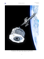
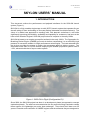
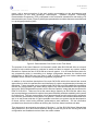
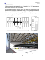
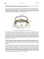
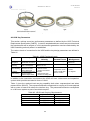
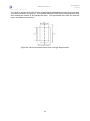
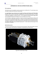
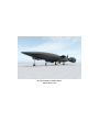
SKYLON Users’ Manual Doc. Number - SKY-REL-MA-0001 Version – Revision 2 Date – May 2014 Compiled: Mark Hempsell Checked: Roger Longstaff Authorised: Richard Varvill Document Change Log Revision 1 1.1 2 2.1 Description Date First issue of document Nov 2009 Minor Corrections and revisions Jan 2010 Major revision in light of D1 work and the European Space Agency study into a SKYLON based European Launch System May 2014 Minor Corrections and revisions June 2014 Contact One of the purposes of this document is to elicit feedback from potential users as part of the validation of SKYLON’s requirements. Comments are most welcome and should be sent to: Reaction Engines Ltd Building D5, Culham Science Centre, Abingdon, Oxon, OX14 3DB, UK Email: [email protected] © Reaction Engines Limited – 2014 SKYLON USERS’ MANUAL © Reaction Engines Limited – 2014 Reaction Engines Ltd Building D5, Culham Science Centre, Abingdon, Oxon, OX14 3DB UK Email: [email protected] Website: www.reactionengines.co.uk SKY-REL-MA-0001 SKYLON Users’ Manual Frontispiece: SUS Upper Stage Approaching SKYLON ii Revision 2 SKY-REL-MA-0001 SKYLON Users’ Manual Revision 2 SKYLON Users’ Manual Contents Acronyms and Abbreviations v 1. INTRODUCTION 1 2. VEHICLE AND MISSION DESCRIPTION 3 2.1 SKYLON Vehicle 2.2 SABRE Engine 2.3 Typical Mission Profile 3 6 7 3. PAYLOAD PROVISIONS 9 3.1 Deployed Payload Mass 3.2 Injection Accuracy 3.3 In orbit Manoeuvring Capability. 3.4 Envelope and Attachments 3.5 Payload Mass Property Constraints 3.6 Environment 3.7 Payload Services 3.8 Mission Duration 4. GROUND OPERATIONS 9 12 12 12 16 17 19 20 21 4.1 Spaceport Description 4.2 Payload Integration 4.3 Launch and Landing Sequence 21 21 26 APPENDICES Note on Appendices 30 APPENDIX A UNIVERSAL SPACE INTERFACE SYSTEM (USIS) 31 A1 Introduction A2 USIS Status A3 USIS Key Parameters 31 31 33 iii SKY-REL-MA-0001 SKYLON Users’ Manual Revision 2 Contents continued APPENDIX B SKYLON UPPER STAGE (SUS) B1 Introduction B2 SUS Description B3 SUS Mission Profile B4 Payload Interfaces 35 35 35 36 40 APPENDIX C SKYLON ORBITING FACILITY INTERFACE (SOFI) C1 Introduction C2 SOFI Description C3 Payload Interfaces 41 41 41 41 APPENDIX D SKYLON PERSONNEL / LOGISTICS MODULE (SPLM) D1 Introduction D2 System Outline D3 Payload Provisions 43 43 43 45 APPENDEX E SKYLON LARGE PAYLOAD CARRIER (SLPC) E1 Introduction E2 Description 47 47 47 APPENDEX F SKYLON SMALL PAYLOAD CARRIER (SSPC) F1 Introduction F2 SSPC Description 49 49 49 iv SKY-REL-MA-0001 SKYLON Users’ Manual Acronyms and Abbreviations A Ampere APU Auxiliary Power Unit ASAP Ariane Structure for Auxiliary Payloads °C Degrees Celsius CG Centre of Gravity CP Centre of Pressure CSG Centre Spatiale Guiana CTB Cargo Transfer Bag dB Decibel DC Direct Current deg Degree ESA European Space Agency EVA Extra-vehicular Activity FAA Federal Aviation Administration g Surface acceleration due to Earth’s gravity GTO Geostationary Transfer Orbit GTOM Gross Take-off Mass H2 Hydrogen hr Hour IBDM International Berthing and Docking Mechanism IDSS International Docking System Standard ISO International Organisation for Standardisation ISS International Space Station K Kelvin kg Kilogram km Kilometre kN Kilonewton kPa Kilopascal kW Kilowatt LEO Low Earth Orbit LH2 Liquid Hydrogen LN2 Liquid Nitrogen LO2 Liquid Oxygen m Metre MECO Main Engine Cut-off MEO Medium Earth Orbit MGSE Mechanical Ground Support Equipment min Minute v Revision 2 SKY-REL-MA-0001 SKYLON Users’ Manual Acronyms and Abbreviations Continued mm Millimetre MN Meganewton MW Megawatt N Newton NASA National Aeronautics and Space Administration Pa Pascal RMS Root Mean Squared s Second SABRE Synergetic Air-breathing Rocket Engine Sec Second S-ELSO SKYLON Based European Launch Service Operator SI Specific Impulse SLPC SKYLON Large Payload Carrier SOFI SKYLON Orbiting Facility Infrastructure SOMA SKYLON Orbital Manoeuvring Assembly SPLM SKYLON Personnel / Logistics Module SSPC SKYLON Small Payload Carrier SSTO Single Stage To Orbit SUS SKYLON Upper Stage TBD To Be Determined TDP Technology Demonstration Programme USIS Universal Spacecraft Interface System V Volt W Watt vi Revision 2 SKY-REL-MA-0001 SKYLON Users’ Manual Revision 2 SKYLON USERS’ MANUAL 1. INTRODUCTION This document outlines the performance and payload interfaces for the SKYLON launch system (Figure 1). SKYLON is a fully reusable single stage to orbit (SSTO) launch system that operates like an aircraft, taking off from and landing on a runway having undertaken its orbital mission(s). The vision of a radical new approach to reaching orbit, with dramatic reductions in cost while significantly improving the reliability, availability and capability for customers, has been at the heart of the Reaction Engines’ SKYLON project since its inception in the early 1990s. SKYLON is based on an engine concept first outlined in the early 1980’s. The Synergetic AirBreathing Rocket Engine (SABRE) pre-cools air before compressing it to a sufficiently high pressure for use as the oxidiser in a high performance rocket engine. The heat extracted from the air then provides the energy to power the compressor and fuel delivery pumps. The achievable mass ratio for SSTO vehicles employing the SABRE propulsion system rises to ~23%; almost double that of a pure rocket system. Figure 1: SKYLON in Flight (Configuration D1) Since 2009, the SKYLON project has been in a development phase (as opposed to concept exploration phase). The work has concentrated on the key new technology required to realise these engines, the lightweight pre-cooler heat exchanger. There have since been over 25 years of research and evaluation of SABRE engines and the airframes they are designed to 1 SKY-REL-MA-0001 SKYLON Users’ Manual Revision 2 power, with a large proportion of the work mainly concentrating on the development and demonstration of the heat exchanger technologies. Reaction Engines’ Technology Demonstration Programme (TDP) culminated in the successful manufacture and testing of a demonstration pre-cooler (Figure 2) with flight representative modules that were manufactured in a prototype production plant. Figure 2: Demonstration Pre-Cooler on the Test Stand The purpose of the Users’ Manual is to illustrate in detail what SKYLON will offer as a launch system to help outside parties to evaluate its worth and also to support any system studies that wish to explore the use of SKYLON as a launch system. It is not intended as a basis for any programme which is committing to a design configuration because the interface and performance of SKYLON may vary later in light of further design and further stakeholder feedback as the vehicle’s development programme progresses. In addition to the interface description of the main SKYLON vehicle this manual has several appendices in which the performance and interfaces for various supplementary elements are described. These elements can be combined with SKYLON to provide additional capabilities that are not incorporated in the basic design. Most of the elements described were produced during the “SKYLON-based European Launch Service Operator” study that was conducted for ESA in 2013/2014. These are not at the same design maturity as SKYLON but rather they are concept designs produced to explore the system feasibility and also establish priority areas for further work. They are conservative in their approach and as such are thought to represent the minimum performance such systems can provide. However the interfaces described here are in no way frozen and also it is quite possible more than one system may be developed to fill these various roles having different performances and interfaces. So the information provided here should not be taken as defining the final form these interfaces will take. This document is an extensive reworking of Revision 1.1 of the SKYLON Users’ Manual that was published in 2010 and reflects both the design revision as part of the evolving SKYLON configuration and feedback received from the earlier release 2 SKY-REL-MA-0001 SKYLON Users’ Manual Revision 2 2. VEHICLE AND MISSION DESCRIPTION 2.1 SKYLON Airframe The SKYLON configuration D1 is an orbital reusable spaceplane that incorporates the SABRE 4 engine. This engine can operate in either an air-breathing or a pure rocket mode. The vehicle takes off from an extended runway with the engines in air-breathing mode. It accelerates to Mach 5.14 and 28.5 km altitude before switching over to the pure rocket mode and climbing to a Low Earth Orbit. Once the payload is deployed and operations in orbit are completed, the vehicle returns to earth, re-enters the atmosphere and glides back to a runway landing. Figure 3 shows the overall layout of SKYLON and also defines the axes that are used in this document for the purposes of orientation. These axes are the SKYLON design axes, which follow the aircraft convention (also used by the Space Shuttle). AXIS X Y Z Sense Longitudinal Lateral Vertical Control Axes Roll Pitch Yaw Sense + X Rear, -X Front +Y Starboard, –Y port +Z up, -Z down Figure 3: SKYLON Layout and Design Axes The airframe (Figure 4) consists of a slender fuselage containing the propellant tanks and the payload bay, with a delta wing located roughly midway along the fuselage. The SABRE engines are mounted in axisymmetric nacelles on the wingtips. Control authority whilst in the atmosphere is exerted by foreplanes in pitch, ailerons in roll and an aft mounted fin in yaw. Yaw control during the rocket ascent is achieved by differential engine throttling. During the rocket ascent, main engine gimballing takes over pitch control progressively as the dynamic pressure reduces, until finally handing over to reaction control thrusters at Main Engine CutOff (MECO). The reaction control thrusters retain the control authority until a progressive handover back to the foreplanes, ailerons and tailfin during re-entry to the Earth’s atmosphere. 3 SKY-REL-MA-0001 SKYLON Users’ Manual Figure 4: SKYLON D1 Airframe 4 Revision 2 SKY-REL-MA-0001 SKYLON Users’ Manual Revision 2 The SKYLON vehicle was found to be very sensitive to the factors affecting Centre of Pressure (CP) and Centre of Gravity (CG) and the configuration was strongly driven to ensure that pitch control authority was maintained throughout all flight phases. This was achieved through a combination of careful attention to the overall aerodynamic shape and mass distribution; sizing of aerodynamic control surfaces; and differential burn-off from the two hydrogen tanks. Part of the solution to the trim issue was to mount the payload as far forward in the bay as practical. Two mounting provisions were included; one 3m aft of the front of the bay, and the other 3m forward of the rear of the bay. However in light of this mass properties constraint, only the forward mounting could carry a full payload, meaning that payloads tend to face backwards, and would experience primarily negative longitudinal accelerations as a result, compared with conventional launch systems. SKYLON’s main structure consists of a space frame constructed from struts made from titanium with silicon carbide fibre reinforcement. The non-structural aluminium propellant tanks are suspended within the framework by Kevlar ties. The frame is covered with sheets of a reinforced glass ceramic material which acts as the aeroshell and main thermal protection backed by a multilayer metallic heat shield. In addition to the main propulsion system tanks there are a set of secondary cryogenic tanks which feed the orbital manoeuvring engines, the reaction control thrusters and the fuel cell power supply. The SKYLON Orbital Manoeuvring Assembly (SOMA) engines on the D1 configuration use a design concept produced by Airbus Defence and Space. The SOMA is an expander cycle with a single turbine powering both the oxygen and hydrogen pumps, and a gearbox to account for their different speed requirements. In order to meet the SKYLON and SUS packaging requirements the pumps feed two thrust chambers. The overall configuration is designed so that two SOMAs can be mounted to produce a four nozzle cluster as shown in Figure 5. SOMA Engine Key Parameters (per twin chambered engine) Thrust Chamber Pressure Mass Throat Diameter Specific Impulse Mixture Ratio Expansion Ratio Total Length 40 kN 90 bar 102.5kg 39.1mm 4562 N sec/kg 5.2: 1 285:1 1328mm Figure 5: Two SOMA Engines as Installed in SKYLON 5 SKY-REL-MA-0001 SKYLON Users’ Manual Revision 2 The SKYLON high level mass breakdown is shown in Table 1 Table 1: SKYLON Mass Breakdown Item Dry Vehicle (inc. margins) Consumables (inc. residuals and auxiliary propellants) Usable Ascent Propellant Nominal Payload Gross Take Off Mass (GTOM) Mass 53.4 6.5 250.1 15.0 tonnes tonnes tonnes tonnes 325.0 tonnes 2.2 SABRE Engine The SABRE 4 engine used in SKYLON D1 is a unique engine concept that can operate in airbreathing mode using LH2 as propellant from take-off to a transition point at ~Mach 5, and then convert to pure rocket engine using LH2 and LO2; the rocket transition was designed to occur at 28km. The engine has only one intended purpose; to power the SKYLON spaceplane. In air-breathing mode, a pre-cooler heat exchanger cools the captured air, so it can then be compressed to high enough pressures to be fed into a rocket combustion chamber. The heat is extracted by a helium loop, which uses the energy extracted from the air (hundreds of MW) to power the compressors and propellant pumps. The helium loop then uses the liquid hydrogen fuel as the heat sink in the thermodynamic cycle. The performance of the SABRE engine is approximately described in Table 2 (note that SKYLON has two SABRE engine nacelles). In air-breathing mode the engine had a continually varying performance as SKYLON follows an optimised lifting, climbing, accelerating trajectory. Table 2: SABRE 4 Characteristics Mode Altitude Range (km) Mach No. Approx. Gross Thrust Approximate Range (MN, per nacelle) Specific Impulse (N s /kg) Air-breathing 0 - 28 0 – 5.5 0.8 - 2 40,000 – 90,000 Rocket 28 - 90 5.2 – 27.8 2 4500 6 SKY-REL-MA-0001 SKYLON Users’ Manual Revision 2 2.3 Typical Mission Profile 2.3.1 Mission Outline SKYLON is designed to be operated in a very similar manner to an aircraft. Payloads would be integrated into the payload bay from above through the payload bay doors; a process very similar to that used to integrate payloads into the NASA Space Shuttle. Once the payload is installed, the vehicle would be towed out to a refuelling ramp located at the end of the runway. The hydrogen, oxygen and helium propellants would then be loaded and the vehicle moved to the roll start point on the runway itself. After all pre-flight checks have been completed the vehicle would start its engines and verify full thrust and nominal operations. Mission control would then give the launch command and the vehicle would release its brakes and accelerate along the runway. At the take-off speed (155m/s) the vehicle would rotate and would be committed to flight. In the event of a malfunction during the take-off run the vehicle would close down all remaining propulsion and brake to a halt on the runway. In the event of a malfunction after the decision point (which commits to the take-off) the vehicle would dump propellant under powered flight and then return to the runway for a landing under gliding flight. Vehicle systems were designed to allow a safe recovery of the vehicle with a complete engine nacelle failure immediately after takeoff. The vehicle follows a climbing, lifting and accelerating trajectory using the engines in airbreathing mode up to a speed just above Mach 5 and an altitude of 28 km. At this point the engines transition to pure rocket mode and the vehicle continues to climb and accelerate to orbital velocity. At the end of powered flight the engines throttle back to limit the axial acceleration to 3g. After Main Engine Cut-Off (MECO) the vehicle makes a small ullage burn using the SOMA orbital manoeuvring engines and dumps all residual propellants from its main tanks. At MECO SKYLON would be in a transfer orbit with an apogee equal to the altitude of the required circular orbit. At apogee the SOMA engines burn again to circularize the orbit. The ascent trajectory up to MECO for a typical launch is shown in Figure 6 Figure 6: A Typical Ascent Trajectory to MECO 7 SKY-REL-MA-0001 SKYLON Users’ Manual Revision 2 Orbital operations would begin with opening the payload bay doors. For missions that involve payload delivery to LEO, the orbital phase of the mission would be completed with the deployment of the payload. However, for missions involving the use of the reusable SKYLON Upper Stage (SUS), the combined SUS and satellite stack would be deployed and manoeuvred to a safe distance from SKYLON. The SUS would then burn its engines to achieve the required transfer orbit (e.g. GTO) and the satellite would then separate and continue its mission autonomously. The SUS would remain in transfer orbit until it returned to perigee, where it would then perform a retro-burn to re-circularise its orbit in phase with the awaiting SKYLON. The SUS and SKYLON would then perform a rendezvous and docking operation, and once this is completed the SUS would be reinstalled into the payload bay. After orbital operations have been completed the vehicle would close its payload bay doors and prepare for re-entry. At a pre-calculated time the vehicle performs a retro-burn with its SOMA engines and begins its descent to the spaceport. Re-entry interface would be passed at an altitude of 120km and the vehicle would manoeuvre in bank and angle of attack in order to control temperatures and heat loads, and in order to meet the pre-calculated downrange and cross range requirements necessary for the return to the spaceport. The vehicle would finally enter a gliding approach and landing schedule that would be almost identical to that of the Space Shuttle. All flight hardware would then be inspected, serviced and prepared for the subsequent flight. A typical descent trajectory is shown in Figure 7. Altitude vs. Time 140000 120000 25 100000 Mach No. Altitude (m) Mach No. vs. Time 30 80000 60000 40000 20 15 10 5 20000 0 0 0 2000 4000 6000 0 8000 2000 4000 Time (secs) Time (secs) Figure 7: A Typical Descent Trajectory to MECO 8 6000 8000 SKY-REL-MA-0001 SKYLON Users’ Manual Revision 2 3. PAYLOAD PROVISIONS 3.1 Deployed Payload Mass Figures 8 to 12 below give SKYLON’s performance for orbital deployment from various launch site latitudes. The graphs show the payload mass delivered into circular orbit plotted against orbital altitude. Each graph has a series of curves for various orbital inclinations. The value for 52° is given as this is the inclination of the ISS, and an inclination of 98° is given as an approximation to a Sun Synchronous orbit. Where the orbit inclination is below the launch site latitude the results are not given in general as these orbits are not practical. The orbital altitudes shown range from 160 km, which is considered the lowest practical earth orbit, to 600 km which has been set as the maximum altitude for SKYLON operations. The ability for SKYLON to return above that altitude has not been fully evaluated, however there is no known reason why SKYLON could not operate at higher altitudes. If altitudes greater than 600 km are of interest please contact Reaction Engines Limited to establish their feasibility and performance. Figure 8: Delivered Mass for Equatorial Launch Site 9 SKY-REL-MA-0001 SKYLON Users’ Manual Figure 9: Delivered Mass for 15 degree Launch Site Figure 10: Delivered Mass for 30 degree Launch Site 10 Revision 2 SKY-REL-MA-0001 SKYLON Users’ Manual Figure 11: Delivered Mass for 45 degree Launch Site Figure 12: Delivered Mass for 60 degree Launch Site 11 Revision 2 SKY-REL-MA-0001 SKYLON Users’ Manual Revision 2 3.2 Injection Accuracy The payload injection accuracy requirements for SKYLON are to have an orbital inclination accuracy of 0.01 degrees prior to deployment and to have the payload achieve a positional accuracy of 10 m and a velocity accuracy of 0.01 m/s after deployment. 3.3 In orbit Manoeuvring Capability. Once in orbit, SKYLON has a 100 m/s capability to perform in orbit manoeuvres not including the deorbit burn. The propellant required to perform such manoeuvres is not included in the basic SKYLON launch mass budget and is charged to the payload mass at 16 kg for each metre a second of additional velocity. 3.4 Envelope and Attachments The SKYLON payload bay (Figure 13) is sized to scope most existing launch system payload envelopes and be appropriate to the 15 tonne mass capability. It is located at the centre of the vehicle over the wing structure and has a U shaped cross section with two doors above it, which, once in orbit, open and expose the payload to space. Figure 13: The SKYLON Payload Bay The bay has two payload interfaces, one in the front and the other at the rear. The front location is stronger and has provisions to eject the payload and also to load cryogenic oxygen, hydrogen and helium, but in all other respects the two interfaces are identical and mirror each other. Proving it meets the mass constraints defined in Section 3.3.4, a payload can, therefore, be placed at either end without alteration. Payloads will use the provision which locates the centre of mass to be within the constraints defined in Section 3.3.3; this will in most cases be the front mounting. It is possible to use both attachments simultaneously to mount two payloads in the bay at one time, providing that when combined, the mass and mass properties constraints are met. 12 SKY-REL-MA-0001 SKYLON Users’ Manual Revision 2 3.4.1 Payload Bay Envelope The volume available to the payload and the location of the payload attachments in the SKYLON payload bay are shown in Figure 14. This is a static volume and assumes a 20 mm allowance for payload dynamic movement outside this envelope. Figure 14: Payload Envelope and Attachment Geometry 13 SKY-REL-MA-0001 SKYLON Users’ Manual Revision 2 3.4.2 Attachment Interface The payload is mechanically attached to SKYLON by three trunnions in a plane: one keel trunnion taking loads along the X and Y axes and two sill trunnions taking loads along the X and Z axes. The position and dimensions of the trunnion hold-down are shown in Figure 15. The attachment is designed to accommodate a 2mm build misalignment in the centreline of the sill trunnion in the payload. Figure 15: Payload Trunnion Attachment Location and Dimensions The trunnions have a ball shaped end where the contact with the mount occurs to ensure that the loads transmitted through the attachment have no torque component and are only those intended. Illustrations of typical installations of both trunnion types are shown in Figure 15. Figure 16: Sill (left) and Keel (right) Trunnions Installed on a Payload. 14 SKY-REL-MA-0001 SKYLON Users’ Manual Revision 2 The sill trunnions that are required to be fitted to the payload are defined by Figure 17. The sill trunnions are intended to be hollowed out to reduce mass but the size of the centre tube is not part of the interface and can be determined by the structural strength requirements. The sill attachment can be opened during the flight to release the sill trunnions and allow the payload to be extracted along the Z axis. Figure 17: Payload Sill Trunnion The forward sill attachment also incorporates a deployment mechanism to eject the payload during flight without the need for any additional equipment Figure 18. The sill attachment opens to release the trunnions and two synchronised actuators push on the sill trunnions with a travel of 200 mm along the guides shown in Figure 15. These guides are supplemented by the keel trunnion which reacts the cantilever loads generated during the deployment. The mechanism accelerates at 0.25 m/s2 to give a release velocity of 0.5 m/s. Figure 18: Sill Attachment and Deployment Mechanism. The keel trunnion that is required to be fitted to the payloads is mechanical defined by Figure 19. The keel trunnion also contains the payload electrical interface with SKYLON as defined in Section 3.7.1. 15 SKY-REL-MA-0001 SKYLON Users’ Manual Revision 2 Figure 19: Payload Keel Trunnion. 3.5 Payload Mass Property Constraints 3.5.1 Overall Centre of Mass Constraints In addition to the overall mass constraint determined by SKYLON’s overall performance (defined in sections 3.1.) there are constraints on the payload mass due to centre of mass constraints imposed by the limitations of SKYLON’s pitch control system during re-entry. The centre of mass versus overall mass constraints which are applicable to the X axis are shown in Figure 20. Figure 20: Maximum Payload Mass versus Payload Centre of Mass along X axis 16 SKY-REL-MA-0001 SKYLON Users’ Manual Revision 2 3.52 Location Mass Property Constraints Table 3 gives the maximum values for the payload mass properties for the forward the rear locations. These values are determined by the design strength of the attachment and its supporting structure. Table 3: Mass Property Constraints – Maximum Values Property Mass x moment y moment z moment Self Inertia X Self Inertia Y Self Inertia Z Forward Location 17000 kg -50000 to +6300 kg m +/-1500 kg m +/-6000 kg m 80000 kg m2 250000 kg m2 250000 kg m2 Rear Location 5000 +/- 10000 kg m +/- 1500 kg m +/- 5000 kg m 20000 kg m2 50000 kg m2 50000 kg m2 3.6 Environment 3.6.1 Static Load Environment The quasi-static design limit loads applicable to the payload are given in Table 4. Table 4: Quasi-Static Design Loads CASE Ascent Re-entry X axis - 3g / + 0.5 g +/- 0.5 g Y axis +/- 0.5 g +/- 0.5 g Z axis + 2.25 g / - 0g + 2.25 g / - 0g 3.6.2 Dynamic Environment The characteristic of the dynamic environment for the Payload has not yet been determined. 3.6.3 Mounting Stiffness The structural stiffness of the SKYLON structure supporting the three trunnion hold-down points has not yet been determined. 3.6.4 Acoustic Environment The acoustic environment in the payload bay has not yet been determined but is expected to be below 100 dB at all frequencies (where 0 dB corresponds to 2 x 10⁻⁵ Pa RMS). 3.6.5 Atmosphere Environment Once the payload bays doors are closed in the integration hall the payload bay is purged to a pure dry nitrogen atmosphere with a pressure of 102 kPa +/- 0.5 kPa and a temperature between +10° C + 40° C. During ascent the nitrogen in the payload bay is vented to the ambient static pressure. During re-entry descent dried air is introduced into the payload bay again to match the ambient static 17 SKY-REL-MA-0001 SKYLON Users’ Manual Revision 2 pressure. Figure 21 shows the pressure history during ascent and re-entry to and from 80 km altitude. Figure 21: Payload Bay Ambient Pressure during Ascent and Descent The design values for the maximum rate of depressurisation during ascent is 700 Pa/sec and the maximum rate of re-pressurisation during descent it is 300 Pa/sec. 3.6.4 Heating Flux While in the payload bay the payload bay wall temperature is between 0°C and 20°C; assuming that the payload is not powered and acting as a further heat source. As the payload bays are not opened until after the operational orbit is reached the payload never experiences any appreciable aerothermal heating loading. 3.7 Payload Services 3.7.1 Disconnectable Electrical Connection Each SKYLON payload attachment point interface has a disconnectable electrical connection which can provide electrical power and some status signals to the payload. This connection is an integral part of the keel trunnion and the pin functions are defined in Figure 22. The payload electrical power connection provides a maximum 15 A at 28 V DC nominal to MIL-STD-704F (for reference, this corresponds to a nominal power of 420 Watts). The total energy available to the payload throughout the mission, starting when payload power supply is connected during integration, is 500 A hr. If two payloads are sharing the bay the maximum current that can be drawn simultaneously is 20 A (for reference, this corresponds to a nominal power of 560 watts). The constraint on the total energy available to the payload over the mission remains as for a single payload. 18 SKY-REL-MA-0001 SKYLON Users’ Manual Revision 2 The connector also provides the payload with a 5 line parallel command / status alert bus. Each signal has an output voltage of 28 V ± 4 V of 2 seconds duration. This provides a 4 bit signal with even parity checking. Four of the commands are reserved; these are: 1000-1 Abort Alert - the SKYLON has initiated an abort manoeuvre 0100-1 Door Opening Alert – the payload bay door will open in 30 seconds 0010-1 Door Closing Alert – the payload bay door will close in 30 seconds 0001-1 Deployment Alert – the payload will be deployed in 30 seconds The actions of other commands are defined by the payload. The payload is required to provide a resistive load greater than 100 ohms which is immune to single point failure. The payload is also required to fully protect the circuit against any overload or voltage overshoot induced by its circuits. Figure 22: Keel Trunnion Pin Connections 3.7.2 Data Bus Connection There is provision for the payload to connect to the SKYLON data bus at both the front and rear interface positions. The precise connection type and its location are not yet established, but it will be located in the area defined in Figure 23. 19 SKY-REL-MA-0001 SKYLON Users’ Manual Revision 2 Figure 23: Payload Connector Location (dimensions in mm) The form of the main SKYLON data bus has not yet been established. It will be a flexible architecture high data rate standard which can be certified to meet aerospace safety requirements. It will be consistent with a connection to SKYLON’s SpaceWire databus architecture. Given the complex interactions this interface generates, it is only available in special circumstances and the compatibility analysis would incur significant extra costs over the basic launch cost for the payload use. It is envisaged that basic infrastructure elements, such as the SUS, SOFI and SPLM, which extend SKYLON’s capability would be used many times. 3.7.3 Propellant Supply The front payload attachment interface has the provision for the payload to connect into SKYLON’s propellant fill, drain and venting system. These provisions are defined in Table 5. Propellant Liquid Hydrogen Liquid Oxygen Helium Connections 1 Fill/drain 1 Fill/drain 2 Fill/drain Temp. 16 K 80 K 4.2 K Press. 2 bar 2 bar 1 bar Rate TBD TBD TBD Table 5: Propellant Delivery Connections The exact nature of these connections has not yet been determined but their location is in the area defined in Figure 23. These capabilities are expected to be used with upper stages using cryogenic propellants, such as the SUS, or systems like the SPLM, which use fuel cells to generate electrical power. Given the complex interactions this interface generates, it is only available in special circumstances and would incur significant extra costs over the basic launch cost for the compatibility analysis. 3.8 Mission Duration SKYLON can remain on orbit for up to 4 days. This must include any contingency time to handle any problems that might develop during the mission, so it is anticipated in most instances the nominal mission time would be no more than 2 days. 20 SKY-REL-MA-0001 SKYLON Users’ Manual Revision 2 4. GROUND OPERATIONS 4.1 Spaceport Description SKYLON operates like an aircraft. Its integration and servicing occur in a hangar, it is supported horizontally on its undercarriage and for flight it is towed out to a runway for fuelling and take-off. The location and detailed design of the launch site or sites have not yet been established; therefore this section describes an idealised flow for launch facilities and operations which would alter from port to port and operator to operator. It follows that the interfaces defined here are more indicative and illustrative than definitive. Figure 23 shows a conceptual spaceport layout. It centres on a 5.5 km runway for exclusive use by the SKYLON vehicle and a 3.2 km runway for aviation use. The operators of SKYLON fleets have separate hangars and payload support facilities. There is a general SKYLON maintenance building used by all operators. Figure 24: Conceptual Spaceport Layout. 4.2 Payload Integration 4.2.1 Integration Facilities It is anticipated that payload launch preparation would occur in special areas as part of the hangar and that overhead cranes would carry the payload from its mechanical support equipment rig in the preparation area to the SKYLON vehicle to be lowered into the payload bay. A concept design for this facility is given in Figure 25 and an artist impression of the interior in Figure 26. The air quality in the payload integration and loading areas is to ISO 9 as defined in ISO 14644-1, “Clean rooms and associated controlled environments--Part 1: Classification of air cleanliness”. 21 SKY-REL-MA-0001 SKYLON Users’ Manual Revision 2 While most payload preparation operations would be conducted in this facility, any propellant loading required by the payload would be done in a separate fill area. The fuelled spacecraft would then be returned and ready for integration The payload is lifted from its integration fixtures and lowered into the payload bay by an Integration frame (such as the one described in Section 4.2.3) carried by an overhead crane. The frame attaches to the payload and once the payload bay is integrated the fame is disconnected and SKYLON’s hold-downs clamps are activated. The electrical connectors in the keel trunnion are made by the loading without further action. If data bus or propellant connections are required they are made by hand and are accessed from the ground access doors, while the payload is mounted in the bay. Figure 25: SKYLON Hangar and Payload Integration Facility Figure 26: Interior of SKYLON Payload Integration Facility 22 SKY-REL-MA-0001 SKYLON Users’ Manual Revision 2 4.2.2 Payload Bay Access The main access to the payload bay and the means by which payloads enter the bay is the payload bay doors on the upper surface that. There are two which hinge on the sill to give a full width and full length access as can be seen in the payload envelope definition in Figure 27. In addition to the main payload bay doors there are two side access doors to the payload bay. These are intended for service access and in the event of passenger module the route for passengers and crew to enter and leave it once the module is installed. The location and size are shown in Figure 27. One is at the front of the bay on the port side and the other at the rear on the starboard side. They are positioned in this way in order to enable the same access to the payload whether it is located in the front or rear payload mounting interface. The door opening is sized to correspond to a FAA Type B emergency exit [FAR Part 25 Section 807]. Figure 27: Payload Bay Access Doors 4.2.3 Payload Integration Frame The payload would be inserted into the payload bay from above through the open bay doors by a crane and an integration frame. A standard frame has been designed as a concept study and it is expected that such an integration frame would be part of the SKYLON operator’s ground support inventory, the cost of an integration frame would be low compared to other launch related costs so it would be entirely reasonable for a payload to use a specialist frame and such frames are both possible and are expected in real operations. The main connection to the concept frame is by the sill trunnions but as the frame could not reach the keel trunnion a special provision was required to react the moments. The frame supports two options: Option A was an integration trunnion mounted on top the payload that attaches to a sleeve in the mounting frame, whereas Option B was to have pairs of integration trunnions in line with the sill trunnions which would attach to a moveable beam that is part of the integration frame. These two options are illustrated in Figure 28. 23 SKY-REL-MA-0001 SKYLON Users’ Manual Revision 2 Figure 28: Integration Frame Showing Option A – Top Trunnion (left) and B – Side Trunnion (right) Figure 29 shows the dimensions for the main and single integration trunnion for Option A Figure 29: Integration Frame Option A Trunnion Location Figure 30 shows the possible locations of the side mounted integration trunnions. The two integration trunnions are in line with the main trunnion and can be located either side of it at fixed points 1.42 m apart. 24 SKY-REL-MA-0001 SKYLON Users’ Manual Revision 2 Figure 30: Integration Frame Option B Trunnion Location Options Both options use the same integration trunnion design and this is shown in Figure 31. It is assumed that the center of the trunnion would be removed to create a tube and hence save payload mass. However the wall thickness of this tube is not fixed and can be determined by the strength required by the payload. Figure 31: Integration Trunnion Dimensions. 25 SKY-REL-MA-0001 SKYLON Users’ Manual Revision 2 4.3 Launch and Landing Sequence Table 6 details the sequence of events from payload integration to take-off, which nominally takes a nominal 3 hours 10 minutes + an orbit phasing delay of up to 180 minutes. The time cannot be extended further as, after SKYLON is fuelled, there is a 240 minute window before the flight attempt must be abandoned and the vehicle de-fuelled. Table 6 also shows the ground operation sequence of event after landing. The time from vehicle stop until the payload is removed is 2 hours. A nominal 1 day is show for post flight servicing which is the expected fast turnaround but this could be longer depending on how it is operated. Table 6: Ground Operations Sequence and Timing ACTIVITY Pre-flight preparation TOTAL TIME ALLOCATED 15 mins Turn-On System Initialisation 10mins 3mins 5mins Connect tow truck umbilical Physical (walk around) - checks of airframe Parallel activity Check of payload interfaces Parallel activity Internal (visual) check of payload bay Checks/purging of fluid lines Parallel activity Parallel activity Flight systems turn-on and stabilise Load Mission profile Verification of load integrity and cross-checks (see also Data Integrity Power line checks, including stability Payload installation Complete Loading 29mins 30mins Unpack payload from shipping crate, check handling paperwork Attach cradle Attach lifting cable Check lift Support/lift payload to safe storage position Carry out visual checks Complete incoming inspection paperwork When all SKYLON checks have been completed, lift payload across to SKYLON lower into payload bay Close mechanical latches Manually disconnect lifting cradle Lift cradle free of SKYLON Close doors COMMENTS Check SKYLON serviceable (check repair records and service intervals) and paperwork up-to-date Preliminary weather check downrange (lightning) Preliminary Range Safety checks Submit flight plan. Ground controllers alerted. Ground facilities alerted (including tow truck planning); Range Safety alert; Mission Control informed Receive Launch authority Launch authorised Initial flight system checks ELEMENTS 10mins 26 Parallel activity Parallel activity Parallel activity Then wait for permission to proceed with launch preps. Shipping payload crate special for CSG. All tasks up to Wait stage can be done ahead of actual loading activity SKY-REL-MA-0001 SKYLON Users’ Manual ACTIVITY Prepare for towing Ready for tow Tow to Preparation Area Propellant Loading SKYLON Fuelled Start thermal conditioning of fuel cells Final pre-flight checks TOTAL TIME ALLOCATED 13mins ELEMENTS Confirm communications functionality Systems check (auto) Verification Launch control, Facilities, Range Safety and Mission Control informed (status) SKYLON cleared for towing 10mins Tow via apron to Preparation Area 40mins Install on take-off apron for fuelling Draw vacuum in filler tube Tank chill down (H2 boils off until tank is cold) Propellant loading and top-off Confirm communications functionality Electrical checks Switch to internal power Disconnect umbilicals Activate APUs Repeat electrical checks Check control surface and software functionality Check brakes Launch control, Facilities, Range Safety and Mission Control informed (status) ‘GO’ received from all services and agencies, or ‘HOLD’ to await next launch opportunity Tow forward to Starter Strip COMMENTS Position SKYLON near to storage tank Install pipes and run LN2 through Connect to liquid Helium source and fill to cool. Drain and recover helium Connect LH2 and LO2 pipes and fill. Fill to 95% then top off 10mins 14mins Ready for departure Phasing hold Start take-off run Take-off (Mission start) Revision 2 0 1 to 120 min 0 MISSION Landing (Mission end) Runway Safe SKYLON Stationary Tow to fuelling area Excess Fuel Management 5mins 1min SKYLON safe to approach ‘Ready-to-tow’ clearance to tow truck 30min 16min SKYLON back-tracks runway and towed to fuelling area Pump out excess fuel Repeat pre-launch functional checks Range safety alert (stand down); Controller alert (SKYLON still functional and status); Facilities alert (e.g. fire services stand down). Mission Control (mission completed and mission data available) Controller alert: SKYLON ready to be towed 27 Fuel tanks may be entirely gaseous at this stage. SKY-REL-MA-0001 SKYLON Users’ Manual ACTIVITY TOTAL TIME ALLOCATED Continue tow Tow to hangar Install in hangar 1min 15min 10min Hangar Operations 10min Open doors Remove payload 5min 25min Post-flight servicing of vehicle 1 day Vehicle storage ELEMENTS ‘Ready-to-tow’ clearance to tow truck SKYLON towed back to hangar Tow-truck manoeuvers SKYLON Hangar doors close SKYLON secured in designated parking position Payload processing area purged with clean air Check environmental levels correct Alert Controllers: SKYLON in hangar Re-test crane to SKYLON Attach lifting cradle to crane Double-check security of lifting equipment Open mechanical latches Lower crane into payload bay Lift payload clear of payload bay Manoeuver lifting cradle away from SKYLON Return payload to MGSE handling equipment Update SKYLON Operating Logs, etc. Thoroughly Inspect vehicle and carry out flight data performance checks. Several servicing staff members with specialist knowledge and skills Storage after arrival/servicing (above) 28 Revision 2 COMMENTS Decide whether any vehicle equipment has malfunctioned and needs repair, or vehicle is scheduled for routine maintenance. Carry out routine inspections SKY-REL-MA-0001 SKYLON Users’ Manual Revision 2 SKYLON USERS’ MANUAL APPENDICES APPENDIX A: UNIVERSAL SPACE INTERFACE SYSTEM (USIS) APPENDIX B: SKYLON UPPER STAGE (SUS) APPENDIX C: SKYLON ORBITING FACILITY INTERFACE (SOFI) APPENDIX D: SKYLON PERSONNEL /LOGISTICS MODULE (SPLM) APPENDIX E: SKYLON LARGE PAYLOAD CARRIER (SLPC) APPENDIX F: SKYLON SMALL PAYLOAD CARRIER (SSPC) 29 SKY-REL-MA-0001 SKYLON Users’ Manual Revision 2 Note on Appendices These Appendices describe and present the user interfaces for various elements which are intended to complement SKYLON and give it additional capabilities over the basic vehicle. Utilisation studies have shown that the majority of payloads (around 80%) will require the use of one of these elements. The designs reflected here are far more conceptual than the design definition of the SKYLON vehicle, and consequently may not reflect the final designs which will enter operation. Nor are they likely to be the only systems fulfilling the various roles; for example it is expected there will be several competing upper stages differing in size, technology, operational philosophy and cost. Eventually, as they come to realisation, all of these systems will have independent Users’ Manuals. They have been included here to give a more complete picture of how SKYLON will appear to users on entry to service. It is hoped that, by providing this broader picture of an operational SKYLON, better feedback can be obtained on the suitability of the configuration to meet real operational needs. 30 SKY-REL-MA-0001 SKYLON Users’ Manual Revision 2 Appendix A: Universal Space Interface System (USIS) A1 Introduction This Appendix describes the Universal Space Interface System (USIS) which is concept for an interface which acts as a universal physical interface between all medium and large space systems whether manned or unmanned. It is intended to be used as the main launch system interface and thus is used on both the SKYLON Large Payload Carrier (Appendix E) and the SKYLON Upper Stage (Appendix B) as the means of attaching the payload to the launch system. It is also used by the SKYLON Orbiting Facility Interface (Appendix C) and SKYLON Personnel / Logistics Module (Appendix D) Thus the USIS is envisaged as being the interface that would be used by virtually all of the payloads. These are all conventional spacecraft types that currently would use a structural ring connection, typically utilising a Marmon clamp release mechanism. However, the new operational environment created by SKYLON means that the “one-shot” mechanism is less appropriate, and a mechanism that can allow recapture of payloads in orbit for return to Earth is a capability that should be included as part of the S-ELSO package to its customers. The use of USIS also allows operational and performance advantages; for example, the SUS USIS that is used as the Payload interface is also the means by which it is recovered in orbit when its mission is complete. A2 USIS Status The USIS concept is currently defined by the “USIS Technical Requirement Specification” which is currently jointly controlled by Reaction Engines Limited and Hempsell Astronautics Limited. It is the intention that this specification will placed under the control of an independent association owned by stakeholders. This association will define a USIS technical standard that meets the requirements. Thus it is not possible to give a definitive technical interface for the USIS. There have been two technical concept designs. An initial USIS design was produced by Reaction Engines for use in the SKYLON Utilisation studies (Figure A1). It is this design that is shown on the SKYLON Orbiting Facility Interface and SKYLON Personnel / Logistics Module Figure A1: Reaction Engines Early USIS Concept Design. 31 SKY-REL-MA-0001 SKYLON Users’ Manual Revision 2 The Reaction Engines USIS had an interface ring which incorporates two seals and has an outer diameter of 1620 mm and an inner diameter of 1480 mm. A more comprehensive concept design for the USIS has been produced by QinetiQ Space nv (Figure A2). This design is derived from the technologies behind the International Berthing and Docking Mechanism, (IBDM) under development in an ESA programme and which is compatible with the IDSS standard. The IBDM technologies include the dual hook mating connection and the Stewart Platform mounted capture ring. Figure A2: QinetiQ Revised USIS Concept Design The QinetiQ USIS concept exploits Stewart Platform mounted capture ring technology, not only to reduce the loads during the capture process, but also to play a part in meeting the misalignment requirements. Thus the capture system operates as an active platform that is steered with the supporting linear actuators. The platform actively aligns during capture of the mating vehicle. To do so, the relative position and orientation of the vehicles would be obtained from the vehicles’ guidance and navigation control system. This reduces the size of the capture guide vanes, helping to meet the passageway requirements while keeping the ring diameter down to 1800 mm. The QinetiQ USIS uses 12 active hook mechanisms to make the structural connection. The loads on the mechanism were very similar when carrying 10 tonnes unpressurised and when carrying the pressurised loads, confirming the close match between these two cases (which was the fundamental insight that led to the concept of a common universal connection standard). A key feature of the USIS concept is that it is intended to have many variations with different levels of complexity and functionality. There would be both pressurised and unpressurised versions with different capabilities from permanent or semi-permanent connections, through berthing connections to full docking connections. The objective was to produce a technical definition for the USIS that both meets the requirements and allows for a wide range of different technical implementations, including simple and light-weight designs, while retaining universal connectivity between them. For example the QinetiQ concept produced three unpressurised USIS variations for the S-ELSO system, shown in Figure A3: 32 SKY-REL-MA-0001 SKYLON Users’ Manual Revision 2 Figure A3: Three Unpressurised USIS Variations A3 USIS Key Parameters This section outlines some key performance parameters as defined by the USIS Technical Requirement Specification (Draft E). It must be emphasised these values are provisional and the requirements will be subject of a full requirements generation exercise conducted by the USIS controlling authority when it is established The various levels of connection for the USIS and the key design parameters are defined in Table A1 Table A1: USIS Functional Levels Description Maximum Contact Maximum Velocity Contact Forces Level I Integrated Level II Berthing Level IIIHard Docking Level IVSoft Docking Permanent or breakable connection In orbit connection with a manipulator In orbit connection between two free flying spacecraft As hard docking with active control to reduce impact loads Negligible Ground handling Nominally zero Below .01 m/s Linear axial 0.1 m/sec all other 0.04 m/sec Angular axial 0.4 deg./sec all other 0.15 deg./sec Maximum150 N Compression 10 kN Linear 4 kN all other Moment 3 kN m Maximum Misalignment Integration tolerences 30 mm 110mm + 5 degrees In addition to the connection requirements the USIS will have a disconnect and separation system which provides a maximum force of 10 kN Table 2 gives the required load carrying capability both when unpressurised and when pressurised to 200 kPa. The unpressurised case corresponds to carrying a 10 tonne payload with a centre of mass 2.5m above the interface ring. The pressured connection corresponds to a 100 tonne system as part of an orbital complex. Table A2: USIS Load Carrying Requirements Load Unpressurised Pressurised Axial Compressive 590 kN 100 kN Axial Tension 300 kN 100 kN Shear 200 kN 120 kN Moment 500 kN m 300 kN m Torque 80 kN m 80 kN m 33 SKY-REL-MA-0001 SKYLON Users’ Manual Revision 2 The USIS is required to be able to have a pressurised passageway through the pressurised connection as shown in Figure A4. This enables astronauts in EVA suits to pass through, and also enables the transfer of ISS equipment racks. The specification also calls for electrical power and databus connections. Figure A4: USIS Pressurised Hatch Clear Passage Requirements 34 SKY-REL-MA-0001 SKYLON Users’ Manual Revision 2 APPENDIX B: SKYLON UPPER STAGE (SUS) B1 Introduction SKYLON has only the capability to place payloads into Low Earth Orbit. To reach higher orbits and Earth escape orbits requires an upper stage. It is anticipated many commercial upper stages would be developed for SKYLON filling specialist market needs and trying to exploit some technical or commercial innovation. However there will be one stage that is developed as part of the SKYLON system to provide a full launch capability on entry into service. This is called the SKYLON Upper Stage (SUS) and this appendix describes and defines the user interfaces for the SUS The SUS stage is optimised to provide the maximum payload into geostationary transfer orbit from a once round suborbital deployment. However it can also deliver effective payloads to all high earth and planetary escape orbits using both sub-orbital and orbital deployment and it can also lift payloads into Low Earth Orbit that are substantially heavier than SKYLON alone can achieve using down range suborbital deployment. In most cases the SUS stage can be recovered for reusability. B2 SUS Description The SUS concept described here (Figure B1) was produced by Thales Alenia Space and has been optimised for the placement of satellites into geostationary Transfer Orbit. Figure B1 SKYLON Upper Stage 35 SKY-REL-MA-0001 SKYLON Users’ Manual Revision 2 The SUS has an aluminium structure which mounts on the forward payload attachment. Enclosed within the main framework is aluminium hydrogen and oxygen tanks which have a common bulkhead. The ullage gas is helium which stored as a liquid in four tanks at the base. The tanks fed a single SOMA engine which is identical to the engine used by SKYLON’s orbit manoeuvring system. Attitude control is achieved with a 24 cold gas thrusters using the hydrogen boil off. The hydrogen and oxygen are also used to supply the fuel cells which supply 2 kW of power. The fuel cells are supplemented by of Li-ion rechargeable cells to handle peak power loads. The dimensions of the SUS are shown in Figure B2 Figure B2 SUS Dimensions The SUS is reusable for up to 10 missions. To recover the SUS it would be launched together with a recovery system in the rear payload mount that can dock with the SUS and re-install it in the forward payload mount. B3 SUS Mission Profile The SUS is loaded into the SKYLON payload bay with its payload already integrated but without propellants. The stage can be used in both an expendable and reusable mode. In reusable mode the recovery system also has to be installed in the rear payload location as shown in Figure B3 which shows the SKYLON payload bay after the installation process. Once SKYLON is on the fuelling apron the liquid oxygen and liquid hydrogen propellants for the SUS are loaded as part of the overall loading process through the connections defined in Section 3.7.3. 36 SKY-REL-MA-0001 SKYLON Users’ Manual Revision 2 Figure B3: SUS with Payload Installed in the SKYLON Bay A typical mission to Geostationary Transfer Orbit is shown in figure B4 7 4 2 N 1 3 6 5 1 Skylon in 185km LEO 2 SUS perigee burn into intermediate elliptical orbit 3 SUS and payload in intermediate elliptical orbit 4 SUS perigee burn into GTO 5 Upper-stage and satellite serparation 6 Satellite apogee burn into GEO 7 Upper-stage LEO insertion and recovery 37 Figure B4: GTO Mission with Reusable SUS SKY-REL-MA-0001 SKYLON Users’ Manual Revision 2 The SUS/satellite stack is deployed by SKYLON into a 185 km altitude circular orbit. The SUS then performs a burn to place itself into an intermediate elliptical orbit which provides the phasing needed for eventual recovery. At the next perigee the SUS fires the SOMA again to place itself into a Geostationary Transfer Orbit and then deployed the Satellite. The SUS then completes the orbit and at perigee point fires the SOMA for the last time to place itself back into the 185 km deployment orbit 793 minutes after it left it. This is 9:1 resonant with the orbital period at 185 km and so the SUS can be recovered by the SKYLON that launched it and return it to Earth for reuse. For heavier payloads the SUS can be used as an expendable stage which directly injects the payload satellite into Geostationary Transfer Orbit and then performs a manoeuvre to ensure a safe destructive re-entry. Another approach to launching communication satellites is to use on board electric propulsion to raise the orbit from an intermediate orbit reached by the launch system to the operational geostationary orbit. The use of this approach with the SKYLON/SUS is shown in Figure B5. The SUS satellite places the satellite into a 5900 km altitude circular orbit which is above the inner Van Allen radiation belt. The SUS then returns to SKYLON for recovery and return. The satellite then uses its electric propulsion to spiral out to geostationary orbit which should typically take around 130 to 160 days. Table B1 gives the delivered maximum payload mass to either Geostationary Transfer Orbit or the 5900 km altitude circular orbit. The table also shows indicative masses for the final satellite finally delivered to Geostationary orbit assuming either an on board chemical propulsion systems with a specific impulse of 3140 N sec / kg or an 20 kW electric propulsion thruster Table 4: SKYLON D1/ SUS Performance in Geostationary Missions SKYLON / SUS Mission Maximum Mass of Satellite at Separation from SUS Typical Mass of Satellite into GEO 6.39 tonnes 4.0 tonnes 8.08 tonnes 5.07 tonnes 6.68 tonnes 5.61 tonnes 185 km LEO deployment Reusable SUS, 9:1 resonance return transfer orbit 185 km deployment Expendable SUS, destructive re-entry 300 km LEO deployment Reusable SUS 5,900 km circular MEO 38 SKY-REL-MA-0001 SKYLON Users’ Manual Revision 2 4 8 5 6 2 N 1 3 7 Figure B5: The SKYLON / SUS Electric Propulsion Satellite Mission 39 SKY-REL-MA-0001 SKYLON Users’ Manual Revision 2 B4 Payload Interfaces The key parameters required for mission planning with the SUS are given in Table B2. Table B2: SUS Key Parameters End of mission mass Usable propellant load Recovery system SOMA engine SI SOMA engine thrust 1524 7540 1000 4562 40 kg kg kg N sec /kg kN Includes RCS, fuel cell, and residuals propellant, and helium Makes the SUS total installed mass 9064 kg Allowance for installed equipment on reusable missions Vacuum specific impulse Fixed The baseline payload interface for the SUS is the USIS. The SUS has a one shot release variant of the USIS (which then is a passive docking connector for recovery). The payload can have any variant of the USIS. The longitudinal envelope available to the payload envelope for the SUS is defined in Figure B6. The cross section is as the normal SKYLON deployment envelope defined in Figure 14 which gives a 4.7 m diameter clear circular envelope but offer areas outside. Figure B6: SUS with USIS Interface Payload Envelope A power supply of 28V and 0.5A maximum current is available to the payload which is supplied through the USIS. The commands and telemetry available to the payload are TBD but will be consistent with the data-link provisions of the USIS. 40 SKY-REL-MA-0001 SKYLON Users’ Manual Revision 2 APPENDIX C: SKYLON ORBITING FACILITY INTERFACE (SOFI) C1 Introduction While SKYLON can perform the orbital manoeuvres to rendezvous with orbiting facilities it does not have the provisions required to physically connect, either by docking or berthing, as part of the main airframe. If this function is required it must either be integrated into the payload or a SKYLON Orbiting Facility Interface (SOFI) must be flown with the payload. This appendix describes and defines the user interfaces for the SOFI. The SOFI provides means by which SKYLON with a main unpressurised payload can dock (or berth - as it has provision for both types of operation) with orbiting facilities such as space stations while leaving most of the payload bay available for the main payload which once the SOFI has connected the SKYLON and the facility can be removed. This is a concept design produced by Reaction Engines as part of the 2009 requirement generation studies. It is included here as an illustration of SKYLON’s potential to carry people into space and to support orbiting facilities with delivery of pressurised cargo. C2 SOFI Description SOFI (Figure C1) mounts in the rear payload location and has a standard USIS docking port to connect to the orbiting facility. The port is held in the rear payload bay protrusion by five struts which connect back to a U shaped frame which stretches across the payload bay. This frame is also the structure to which the other equipment and the hold-down trunnions are mounted. Figure C1: SKYLON Orbiting Facility Interface (SOFI) In addition to the docking/berthing port the SOFI carries the radar and optical alignment system needed for final approach and alignment to the orbital facility. It also has a standard grapple point to enable SKYLON and its payload to be captured in free flight and then berthed as opposed to docked if the orbiting facility has a Remote Manipulator System. The design philosophy is that the main payload needs no provisions to reach the facility, except a grapple point if it is required to be removed from the bay. 41 SKY-REL-MA-0001 SKYLON Users’ Manual Revision 2 Although primarily designed to deliver unpressurised payloads the port is a capable of being pressurised. The concept design has added a small pressurised container to the docking port which can carry a double Cargo Transfer Bag up to 50 kg in mass. The flight can therefore be used to deliver a small amount of urgent or otherwise opportune logistics in addition to the main payload. C3 Payload Interfaces The main payload does not connect to the SOFI. The impact on the payload provision is to alter the mass and envelope available to the main payload. The SOFI has an installed mass of around 750 kg which must be subtracted from the performance given in Section 3.1.1 to obtain the mass available to the main payload. The SOFI centre of mass relative to the payload bay centre is: X = 4.56 m, Y = -0.03 m, Z = 0.93 m. It is the combined centre of mass of the SOFI and main payload which must meet the constraints outlined Section 3.3.3. If a Cargo Transfer Bag (CTB) is carried in the pressurised container its centre of mass will be at: X = 5.25 m, Y = 0 m, Z = 1.83 m. The SOFI occupies the rear payload interface and fills the rear 3 metres of the bay. The main cross section is unaltered for an RMS removed payload as defined in Section 3.3.1. However, the length is reduced and the altered envelope is shown in Figure C2. There is a small protrusion over the SOFI U section intended to accommodate the main payload’s attachment (e.g. a docking or berthing port) without using the main cross section. Figure C2: Payload Envelope with SOFI Installed 42 SKY-REL-MA-0001 SKYLON Users’ Manual Revision 2 ANNEX D: SKYLON PERSONNEL /LOGISTICS MODULE (SPLM) D1 Introduction This annex defines the interfaces for the module called the SKYLON Personnel / Logistics Module (SPLM) which enables SKYLON to carry people and logistic supplies to orbital facilities. The mix of passengers and logistics is very flexible, but if optimised for passenger flight it can carry 24 people. This is a concept design produced by Reaction Engines as part of the 2009 requirement generation studies. It is included here as an illustration of SKYLON’s potential to carry people into space and to support orbiting facilities with delivery of pressurised cargo. D2 System Outline D2.1 SPLM Description The SPLM is shown in Figure D1. It is a pressurised structure with an internal cabin diameter of 4 meters and a length of 8.5 meters. Figure D1: SKYLON Personnel / Logistics Module (SPLM) The SPLM adds all the functions to SKYLON for human spaceflight. In addition to a controlled pressurised cabin which stores seating and logistics, it provides a simple galley and thermal control and additional independent video and voice communications links. The primary safety philosophy in the event of an accident is for the cabin to be a survivable safe haven in which the passengers stay until the hazard has passed. It is structurally independent of SKYLON and in a crash uses the SKYLON structure as an energy absorbing “crumple zone”. The exterior has heat shielding which can survive in a fire fuelled by the propellants. The cabin is airtight and its control does not require any functions external to the cabin. Should the cabin integrity be breached the passengers are equipped with simple pressure suits. In the event of an inflight disintegration of the SKYLON vehicle, if the cabin is thrown clear then there is a parachute to reduce the ground impact loads to survivable levels. In the event of an in orbit failure whereby SKYLON is deemed unfit to attempt a re-entry, there is a two day survival life support capability giving time for a second SKYLON equipped with a 43 SKY-REL-MA-0001 SKYLON Users’ Manual Revision 2 SPLM to rendezvous and dock with the stranded SKYLON. Passengers can then transfer to the second SKYLON for return to Earth. The SPLM main cabin (Figure D2) is designed for operational flexibility with 6 bays which can be outfitted for a variety of seating or logistics payloads. There are also 12 storage lockers under the aisle floor for further logistics. Figure D2: SPLM Interior D2.2 Mission Outline The SPLM is loaded into the payload bay the same as other payloads. It mounts in the forward payload location and connects to the SKYLON data bus and the hydrogen and oxygen feeds to fill the internal fuel cell tanks. While it is possible to load even large racks after the SPLM has been installed in SKYLON, this is time consuming and awkward so it is therefore expected that all logistics will have been loaded prior to integration. Once installed any passengers would enter the SPLM. The primary access is by the forward payload bay ground door and a corresponding pressurised door in the SPLM. There is also a rear door in the SPLM as secondary access path which opens to the rear of the payload bay, hence the rear payload bay ground access door. Once all passengers are on-board the SKYLON would be then towed to the refuelling apron to begin the flight. Missions can be up to 2 days, with a further 2 days capability for contingency. Missions to orbiting facilities are possible with a full active USIS docking port in the roof (which can also be used for berthing if appropriate). This port is orientated with 15 degrees rotation to the SKYLON axes so that two SPLM equipped SKYLON’s can dock with each other for in orbit rescue of passengers. Return and landing follows the standard SKYLON re-entry procedure. 44 SKY-REL-MA-0001 SKYLON Users’ Manual Revision 2 D3 Payload Provisions D3.1 Mass Capability The SPLM has an unladen mass of 7800 kg which includes the Captain, hydrogen and oxygen for the fuel cells and some of the life support consumables. The difference between this mass and the mass capability defined in section 3.1 is what is available for passengers and logistics. D3.2 Under Floor CTB Provisions The main logistics provision is designed to house ISS standard Cargo Transfer Bags (CTB) and takes the form of 12 lockers under the aisle floor. Each houses a triple CTB or a combination of double, single and half CTBs up to a mass of 80kg in each locker. D3.3 Cabin Bays The cabin has 6 bays which are configured to house a variety of payload types. The bay’s dimensions are shown in Figure D3. Figure D3: Cabin Bay Dimensions There are two types of passenger seat which can be installed in each bay; upright seats and supine couches. The upright seats are intended for personnel undertaking a short term visit to space (less than 14 days). These seats contain storage provisions for a single CTB for the passenger’s personal luggage. The supine couches are intended for personnel undertaking long term visits to space (over 14 days). These seats contain storage provisions for two single CTBs for the passenger’s personal luggage. The mass allowance for each seat is 190 kg for the upright seat and 195 kg for the supine seats. This includes the passenger, the seat, a 20 kg single CTB for personal effects (stored in the seat) and a pressure suit. The seat also has a 4 day supply of oxygen and lithium hydroxide. As expected, the life support consumables increase as passenger seats are added. Each bay has the basic mounting provisions for one standard ISS Equipment Rack with a mass up to 700 kg. The mounting provisions, the width (1014 mm) and height (2016 mm) remain as the existing ISS standard. However the depth is additionally constrained to 800 mm 45 SKY-REL-MA-0001 SKYLON Users’ Manual Revision 2 (compared with around 900 mm in the existing ISS standard) due to door and hatchway limitations. Each bay can be fitted with a CTB carrier to supplement the permanent under floor provisions. This mounts on the same interface as the ISS Equipment Racks, but it cannot pass through the docking /berthing port and so cannot be moved to the orbiting facility. The CTB Carrier has 9 triple CTB bays in a 3 by 3 array. The carrier structure has a mass of 60 kg. Each bay can carry a total of 80 kg up to a maximum for all 9 bays of 640 kg. The total maximum installed mass for the CTBs and carrier structure is 700 kg. 46 SKY-REL-MA-0001 SKYLON Users’ Manual Revision 2 APPENDIX E: SKYLON LARGE PAYLOAD CARRIER (SLPC) E1 Introduction The SKYLON’s main three trunnion mounting is not necessarily the most convenient arrangement for the potential payloads, particularly payloads follows the current generic form of a cylinder core structure leading to a ring interface with the launch system. Another disadvantage is that the three trunnion mount does not allow for payloads to be captured and reinstalled in the bay on orbit, except when SKYLON is docked to a facility with a manipulator arm. The SKYLON Large Payload Carrier (SLPC) was intended to provide an alternative payload interface that overcomes these problems. It is designed to carry primary payloads in the SKYLON payload bay, in cases where the trunnion mounting is not appropriate. Such cases include: Where the payload’s structure cannot reach the trunnions Where the payload’s structural concept is incompatible with the trunnion mounting Where the payload requires recovery Where the payload requires a USIS for its subsequent mission (e.g. servicing). E2 Description This section describes a design for the SLPC that was produced by QinetiQ Space nv. It responded to requirements that called for a carrier that was based on the USIS and could carry satellites up to 10 tonnes and deploy them once in orbit. Inherent to the USIS is the ability to also dock with satellites that have a passive USIS docking port and return them to Earth. The requirements specify that the SLPC can be mounted in either of the payload attachment points, although in practice it would normally be installed in the forward payload interface as this is the only one strong enough to take payloads of this mass. The requirements also specify that the power and data connections that form part of the USIS standard will be available to the payload. The resulting design is shown in Figure E1. It is a truss frame created from hollow circular tubes made of titanium Ti6Al4V, Figure E1: SLPC Design Shown Stowed (left) and Deployed (right) 47 SKY-REL-MA-0001 SKYLON Users’ Manual Revision 2 The deployment of payloads will necessitate the payload being rotated to vertical from the horizontal launch position due to the orientation of SKYLON’s payload bay and the payload bay doors. The mechanism to achieve this mounts the USIS on a platform which is connected to the main frame by a simple hinge giving a 90 degree rotation capability. When stowed, twelve M12 motor driven powered bolts hold the platform against the frame. Before rotation these bolt connections can be undone, and remade after re-stowing. For deployment a single mechanism consisting of a linear actuator acting on the centre hinge of a two bar arm pushes the frame into position or pulls it back against the frame so that the motor driven bolts can secure the frame and payload for re-entry and landing. The estimated mass for the SLPC is 3 tonnes. And it is strong enough to carry a 10 tonne satellite with its centre of mass 2.5 meters from the USIS interface plane. The longitudinal envelope available to the payload carried is shown in Figure E2, the cross sectional envelope is as for a fixed payload in Figure 13. Figure E2 SLPC Longitudinal Payload Envelope Figure E3: SLPC Deploying a Space Telescope Payload 48 SKY-REL-MA-0001 SKYLON Users’ Manual Revision 2 APPENDIX F: SKYLON SMALL PAYLOAD CARRIER (SSPC) F1 Introduction This Appendix outlines the user interfaces for the SKYLON Small Payload Carrier (SSPC). The purpose of the SSPC is to carry payloads which are too small to be realistically carried by the main SKYLON interface. It is the SKYLON equivalent of the Space Shuttle’s Getaway Special carrier or the Ariane 5 ASAP platform. It gives SKYLON the capability to fly small satellites and fixed payloads. F2 SSPC Description The design concept shown here was produced by QinetiQ Space nv in response to a specification that had been produced in response to feedback from small satellite suppliers received on an earlier SSPC concept. The specification called for the new SSPC to carry four satellites with a common mechanical interface; two of the spaces large enough to carry Minisatellites (up to a mass of 500kg) and two spaces able to carry micro-satellites (up to 100kg). Another new requirement for the SSPC is the capability to launch CubeSats. The QinetiQ design shown Figure F1 is a spaceframe manufactured from aluminium (6060T6), that occupies the space between the Payload Attachment system and the payload bay end walls. It is envisaged the SSPC would normally be mounted in the rear location as a payload of opportunity but is can also be mounted in the forward location. Figure F1: SKYLON Small Payload Carrier with Representative Payloads 49 SKY-REL-MA-0001 SKYLON Users’ Manual Revision 2 The spaceframe supports 4 identical interface rings with a hollow rectangular section. The ring inner diameter was 550mm and the outer diameter 650mm, while the connection to the payload is made by 16 M5 bolts on a 600mm pitch centre diameter. Any separation mechanisms that would be required are assumed to be supplied by the payload itself or from an optional dedicated payload adapter providing this functionality. The Mini-Satellite locations offer an envelope corresponding to a 1500mm cube, and the micro-satellites an envelope with an 800mm square base and a height of 1200mm. These envelopes include any deployment tip-off allowance. The design also allows the payload to protrude below the interface plane by at least 350mm, with up to 1000mm available in the small satellite locations. The SSPC can also carry four NanoSat dispensers mounted on the rear cross member. These satellites were assumed to follow the standard model established by California Polytechnic State University in their CubeSat Design Specification. This specification describes a “P-POD” dispenser able to carry 3U of 100mm CubeSats which was used as the model for the SSPC dispensers. The mass of the SSPC was estimated to be 253kg including a 10% uncertainty factor. When fully loaded this would give an installed mass of under 1500kg, but more typically it was expected that the installed mass will be less than 1000kg. Each bay has a 5 pin electrical connection which provides a nominal 28 watts of electrical power and two commands to the payload. The pin allocation is defined in Table F1. PIN 1 2 3 4 5 Table F1: Electrical Connector Pins FUNCTION SPECIFICATION Power + 28V Nominal , 1 Amp Power Return + 0V Earth + 0V Command 1 28 V ± 4 V for 2 seconds. Command 2 28 V ± 4 V for 2 seconds. The total power drawn by the SSPC has been limited to ensure that the electrical power available to the main payload is not changed by the inclusion of a fully laden SSPC. Figure F2: A Satellite Deploying from the SSPC 50 All CGI artwork by Adrian Mann www.bisbos.com Reaction Engines Ltd Building D5, Culham Science Centre, Abingdon, Oxon, OX14 3DB, UK www.reactionengines.co.uk Email: [email protected]