1
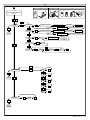
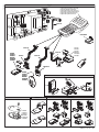
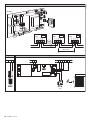
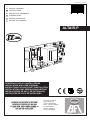
D811506 ver.03 13-06-07 I QUADRO COMANDO GB CONTROL PANEL F CENTRALE DE COMMANDE D STEUERPLATINE E CUADRO DE MANDOS P QUADRO DE COMANDO 8 027908 295484 ALTAIR-P ISTRUZIONI D’USO E DI INSTALLAZIONE INSTALLATION AND USER’S MANUAL INSTRUCTIONS D’UTILISATION ET D’INSTALLATION INSTALLATIONS-UND GEBRAUCHSANLEITUNG INSTRUCCIONES DE USO Y DE INSTALACION INSTRUÇÕES DE USO E DE INSTALAÇÃO Via Lago di Vico, 44 36015 Schio (VI) Tel.naz. 0445 696511 Tel.int. +39 0445 696533 Fax 0445 696522 Internet: www.bft.it E-mail: [email protected] D811506_03 - ALTAIR-P - Ver. 03 D811506_03 MANUALE D’USO ITALIANO USER’S MANUAL ENGLISH Nel ringraziarVi per la preferenza accordata a questo prodotto, la Ditta è certa che da esso otterrete le prestazioni necessarie al Vostro uso. Leggete attentamente l’opuscolo ”Libretto istruzioni” che lo accompagna in quanto esso fornisce importanti indicazioni riguardanti la sicurezza, l’installazione, l’uso e la manutenzione. Questo prodotto risponde alle norme riconosciute della tecnica e delle disposizioni relative alla sicurezza. Confermiamo che esso è conforme alle seguenti direttive europee: 89/336/CEE, 73/23/CEE e loro modifiche successive. Thank you for buying this product, our company is sure that you will be more than satisfied with the product’s performance. The product is supplied with a “Warnings” leaflet and an “Instruction booklet”. These should both be read carefully as they provide important information about safety, installation, operation and maintenance. This product complies with the recognised technical standards and safety regulations. We declare that this product is in conformity with the following European Directives: 89/336/EEC and 73/23/EEC (and subsequent amendments). 1) GENERALITÁ Il quadro comandi ALTAIR-P è adatto per cancelli a battente. Viene fornito dal costruttore con impostazioni funzionali standard. Qualsiasi variazione, deve essere impostata mediante il programmatore a display incorporato o mediante programmatore palmare universale. La Centralina supporta completamente il protocollo EELINK. 1) GENERAL OUTLINE The ALTAIR-P control panel is suitable for swing gates. It is supplied by the manufacturer with standard functional settings. Any alteration must be set by means of the incorporated display programmer or by means of universal palmtop programmer. The Control unit completely supports the EELINK protocol. 2) FUNZIONI PER L’INSTALLATORE: compilare la tabella con in parametri impostati al fine di facilitare future modifiche e manutenzioni. Tra parentesi quadre [ ] sono indicati i valori di fabbrica. Per le logiche di funzionamento, [ OFF ] indica opzione non attiva, [ ON ] indica opzione attiva. 2) FUNCTIONS FOR THE INSTALLER: fill in the table with the parameters set, in order to facilitate future modifications and maintenance operations. The factory-set values are specified within square brackets [ ]. For function logics, [ OFF ] indicates a non-active option and [ ON ] indicates an active option. Menu parametri Tempo lavoro Tempo lavoro pedonale Tempo Chiusura Automatica Tempo sfasamento ante in apertura Tempo sfasamento ante in chiusura Coppia (forza di spinta) motori Indirizzo di zona per comandi centralizzati [ 10s ] [ 6s ] [ 10s ] [ 1s ] [ 1s ] [ 50%] [ 0 ] ___ ___ ___ ___ ___ ___ ___ parametEr MENU Operation time Pedestrian operation time Automatic Closing Time Leaf phase-difference time on opening Leaf phase-difference time on closing Motor torque (pushing force) Zone address for centralised controls [10s] [ 6s ] [10s] [ 1s] [ 1s] [50%] [ 0 ] ___ ___ ___ ___ ___ ___ ___ MENU Logiche Richiusura automatica attiva (TCA) Logica di funzionamento a 3 Passi Blocca Impulsi Pre allarme Chiusura rapida dopo fotocellule Fotocellule in apertura Spia cancello aperto o II° canale radio Comando solo un motore Colpo ariete apertura Radioricevitore a codice fisso Prog. radio Scheda master per comandi centralizzati START-OPEN PED-CLOSE [ OFF ] [ OFF ] [ OFF ] [ OFF ] [ OFF ] [ OFF ] [ OFF ] [ OFF ] [ OFF ] [ OFF ] [ ON ] [ OFF ] [ OFF ] [ OFF ] ___ ___ ___ ___ ___ ___ ___ ___ ___ ___ ___ ___ ___ ___ Logic MeNU Active automatic closing (TCA) 3-Step function logic Impulse lock Prealarm Rapid closing past photocells Photocells on opening Gate-open or 2nd radio channel warning light One-motor control only Ram blow on opening Fixed-code radio receiver Radio programming Master board for centralised controls START-OPEN PED-CLOSE [OFF ] [OFF ] [OFF ] [OFF ] [OFF ] [OFF ] [OFF ] [OFF ] [OFF ] [OFF ] [ON ] [OFF ] [OFF ] [OFF ] ___ ___ ___ ___ ___ ___ ___ ___ ___ ___ ___ ___ ___ ___ 3) DEMOLIZIONE Attenzione: avvalersi esclusivamente di personale qualificato. L’eliminazione dei materiali va fatta rispettando le norme vigenti. Nel caso di demolizione, non esistono particolari pericoli o rischi derivanti dal prodotto stesso. È opportuno, in caso di recupero dei materiali, che vengano separati per tipologia (parti elettriche - rame - alluminio - plastica - ecc.). 3) SCRAPPING Warning: this operation should only be carried out by qualified personnel. Materials must be disposed of in conformity with the current regulations. In case of scrapping, the automation devices do not entail any particular risks or danger. In case of materials to be recycled, these should be sorted out by type (electrical components, copper, aluminium, plastic etc.). 4) SMANTELLAMENTO Attenzione: Avvalersi esclusivamente di personale qualificato. Nel caso la centralina venga smontata per essere poi rimontata in altro sito bisogna: • Togliere l’alimentazione e scollegare tutto l’impianto elettrico. • Nel caso alcuni componenti non possano essere rimossi o risultino danneggiati, provvedere alla loro sostituzione. 4) DISMANTLING Warning:This operation should only be carried out by qualified personnel. When the control unit is disassembled to be reassembled on another site, proceed as follows: • Disconnect the power supply and the entire electrical installation. • In the case where some of the components cannot be removed or are damaged, they must be replaced. 5) AVVERTENZE • Assicurarsi che sia presente sulla rete di alimentazione dell’automazione, un interruttore o un magnetotermico onnipolare con distanza di apertura dei contatti uguale o superiore a 3,5 mm. • Assicurarsi che sia presente a monte della rete di alimentazione un interruttore differenziale con soglia da 0.03A. • Assicurarsi che i dispositivi di sicurezza applicati al cancello siano sempre funzionanti, altrimenti togliere alimentazione, sbloccare i motori e rivolgersi subito a personale qualificato. • Assicurarsi che l’impianto di terra sia realizzato correttamente. • Non permettere a persone e bambini di sostare nell’area d’azione dell’automazione. • Non lasciare radiocomandi o altri dispositivi di comando alla portata dei bambini onde evitare azionamenti involontari dell’automazione. • L’utilizzatore deve evitare qualsiasi tentativo di intervento o riparazione dell’automazione e rivolgersi solo a personale qualificato. 5) WARNING • Make sure that an omnipolar or magnetothermal switch, having a contact opening distance equal to or greater than 3,5 mm, is fitted to the automation power supply mains. • Make sure that a differential switch with a 0.03A threshold is fitted before the power supply mains. • Make sure that all safety devices installed on the gate are always in working order; otherwise, disconnect the power supply, release the motors and immediately request assistance from qualified personnel. • Makes sure that earthing has been carried out correctly. • Do not allow persons or children to remain within the automation operation area. • Keep radio control or other control devices out of children’s reach, in order to avoid unintentional automation activation. • The user must avoid any attempt to carry out work or repair on the automation system, and always request the assistance of qualified personnel. Il buon funzionamento dell’attuatore è garantito solo se vengono rispettate i dati riportati in questo manuale. La Ditta non risponde dei danni causati dall’inosservanza delle norme di installazione e delle indicazioni riportate in questo manuale. Correct controller operation is only ensured when the data contained in the present manual are observed. The company is not to be held responsible for any damage resulting from failure to observe the installation standards and the instructions contained in the present manual. Le descrizioni e le illustrazioni del presente manuale non sono impegnative. Lasciando inalterate le caratteristiche essenziali del prodotto, la Ditta si riserva di apportare in qualunque momento le modifiche che essa ritiene convenienti per migliorare tecnicamente, costruttivamente e commercialmente il prodotto, senza impegnarsi ad aggiornare la presente pubblicazione. The descriptions and illustrations contained in the present manual are not binding. The Company reserves the right to make any alterations deemed appropriate for the technical, manufacturing and commercial improvement of the product, while leaving the essential product features unchanged, at any time and without undertaking to update the present publication. ALTAIR-P - Ver. 03 - D811506_03 ENGLISH INSTALLATION MANUAL Thank you for buying this product, our company is sure that you will be more than satisfied with its performance. This product is supplied with an “Instruction Manual” which should be read carefully as it provides important information about safety, installation, operation and maintenance. This product complies with recognised technical standards and safety regulations. We declare that it is in conformity with the following European Directives: 89/336/EEC, 73/23/EEC and subsequent amendments. 1) GENERAL SAFETY WARNING! An incorrect installation or improper use of the product can cause damage to persons, animals or things. • The “Warnings” leaflet and “Instruction booklet” supplied with this product should be read carefully as they provide important information about safety, installation, use and maintenance. • Scrap packing materials (plastic, cardboard, polystyrene etc) according to the provisions set out by current standards. Keep nylon or polystyrene bags out of children’s reach. • Keep the instructions together with the technical brochure for future reference. • This product was exclusively designed and manufactured for the use specified in the present documentation. Any other use not specified in this documentation could damage the product and be dangerous. • The Company declines all responsibility for any consequences resulting from improper use of the product, or use which is different from that expected and specified in the present documentation. • Do not install the product in explosive atmosphere. • The construction components of this product must comply with the following European Directives: 89/336/CEE, 73/23/EEC, 98/37/EEC and subsequent amendments. As for all non-EEC countries, the abovementioned standards as well as the current national standards should be respected in order to achieve a good safety level. • The Company declines all responsibility for any consequences resulting from failure to observe Good Technical Practice when constructing closing structures (door, gates etc.), as well as from any deformation which might occur during use. • The installation must comply with the provisions set out by the following European Directives: 89/336/CEE, 73/23/EEC, 98/37/EEC and subsequent amendments. • Disconnect the electrical power supply before carrying out any work on the installation. Also disconnect any buffer batteries, if fitted. • Fit an omnipolar or magnetothermal switch on the mains power supply, having a contact opening distance equal to or greater than 3,5 mm. • Check that a differential switch with a 0.03A threshold is fitted just before the power supply mains. • Check that earthing is carried out correctly: connect all metal parts for closure (doors, gates etc.) and all system components provided with an earth terminal. • Fit all the safety devices (photocells, electric edges etc.) which are needed to protect the area from any danger caused by squashing, conveying and shearing, according to and in compliance with the applicable directives and technical standards. • Position at least one luminous signal indication device (blinker) where it can be easily seen, and fix a Warning sign to the structure. • The Company declines all responsibility with respect to the automation safety and correct operation when other manufacturers’ components are used. • Only use original parts for any maintenance or repair operation. • Do not modify the automation components, unless explicitly authorised by the company. • Instruct the product user about the control systems provided and the manual opening operation in case of emergency. • Do not allow persons or children to remain in the automation operation area. • Keep radio control or other control devices out of children’s reach, in order to avoid unintentional automation activation. • The user must avoid any attempt to carry out work or repair on the automation system, and always request the assistance of qualified personnel. • Anything which is not expressly provided for in the present instructions, is not allowed. • Installation must be carried out using the safety devices and controls prescribed by the EN 12978 Standard. 1) GENERAL OUTLINE The ALTAIR-P control panel is suitable for swing gates. It is supplied by the manufacturer with standard functional settings. Any alteration must be set by means of the incorporated display programmer or by means of universal palmtop programmer. The Control unit completely supports the EELINK protocol. Specifications: - management of two motors with electronic torque setting. - Radio receiver: 433.92 MHz rolling-code or fixed code - Maximum numbers of radio control devices to be managed: 63 - Centralised controls with other controllers: presetting for serial protocol with an external accessory. 3) CONTROL UNIT TECHNICAL SPECIFICATIONS Power supply:............................................................... 230V~ ±10% 50Hz* No-load absorption from the mains:.............................................. 0.2A max Mains/low voltage insulation: ........................................ > 2MOhm 500V Dielectric strength:...........................mains/low voltage 3750V~ for 1 minute Motor output current:.........................................................1.25A+1.25Amax Motor relay commutation current:........................................................... 10A Maximum power with 2 motors:................................................300W+300W Maximum power with 1 motor:........................................................... 300W Blinker: . ....................................................................................... 40W max Gate-open warning light:....................................................... 24V~ 3W max Supply to accessories: . ..................................24V~ (0.2A max absorption) Degree of protection for box: ............................................................... IP 55 Dimensions:................................................................................see figure 1 Fuses: ........................................................................................see figure 2 (*other voltages available on request) 4) TERMINAL BOARD CONNECTIONS (Fig.3) WARNING - During wiring and installation operations, refer to the current standards and to principles of good technical practice. Wires powered at different voltages must be physically separated, or suitably insulated with at least 1 mm extra insulation. The wires must be clamped by an extra fastener near the terminals, for example by bands. The capacitors must be inserted inside the control unit box and adequately fixed to it. WARNING! For connection to the mains, use a multipolar cable with a 2 minimum of 3x1.5mm cross section and complying with the previously mentioned regulations. For example, if the cable is out side (in the open), it has to be at least equal to H07RN-F, but if it is on the inside (or outside but placed in a plastic cable cannel) it has to be or at least egual to H05VV-F with section 3x1.5mm2. TERMINAL DESCRIPTION 1 GND terminal (yellow/green earthing cable) 2 Single-phase mains supply (L) 3 Single-phase mains supply (N) 4-5-6 Connection to motor 1: 4 on 1 + Capacitor 5 common 6 on 2 + Capacitor 7-8-9 Connection to motor 2: 7 on 1 + Capacitor 8 common 6 on 2 + Capacitor 10-11 230V ~ output for blinker light (40W max) 13-14 24V~ 180mA max output – supply to photocells or other devices 15-16 Output (N.O. contact (24V~/0.5A max)) for gate-open warning light or, alternatively, 2nd radio channel (see paragraph 6 “configuration”). 17-18 STOP push (N.C.) input. If not used, leave the bridge connected. 17-19 PHOTOCELL (N.C.) input. If not used, leave the bridge connected 17-20 DIP START-OPEN= OFF: START push (N.O.). DIP START-OPEN= ON: OPEN push (N.O.). 17-21 DIP PED-CLOSE= OFF: PEDESTRIAN input (N.O.). Activation only takes place on motor 2 for the Pedestrian operation time, if the opening cycle has started (not from pedestrian function), the pedestrian control is considered as a START control. DIP PED-CLOSE= ON: CLOSE input (N.O.). 31-32 Antenna input for integrated radio-receiver board (31: SIGNAL. 32: BRAID) 5) PROGRAMMING The control panel provided with a microprocessor is supplied with function parameters preset by the manufacturer, suitable for standard installations.The predefined parameters can be altered by means of either the incorporated display universal palmtop programmer. In the case where programming is carried out by means of universal palmtop ALTAIR-P - Ver. 03 - 11 INSTALLATION MANUAL programmer, carefully read the instructions relating to universal palmtop programmer, and proceed in the following way. Connect the universal palmtop programmer to the control unit through the UNIFLAT accessory (See fig. 4). Enter the “CONTROL UNITS” menu, and the “PARAMETERS” submenu, then scroll the display screenfuls using the up/ down arrows, and set the numerical values of the parameters listed below. For the function logics, refer to the “LOGIC” submenu. In the case where programming is carried out by means of the incorporated programmer, refer to Fig. A and B and to the “configuration” paragraph. 6) Configuration The display programmer is used to set all the ALTAIR-P control panel functions. The programmer is provided with three pushbuttons for menu scrolling and function parameter configurations (Fig. 2): + menu scrolling/value increment key - menu scrolling/value reduction key OK Enter (confirm) key The simultaneous pressure of the + and – keys is used to exit the active menu and move to the preceding menu. If the + and – keys are pressed simultaneously at the main menu level (parameters, logics, radio, language, default), programming is exited and the display is switched off (the END message is displayed). The modifications made are only set if the OK key is subsequently pressed. When the OK key is pressed for the first time, the programming mode is entered. The following pieces of information appear on the display at first: - Control unit Software version - Number of total manoeuvres carried out (the value is expressed in thousands, therefore the display constantly shows 0000 during the first thousand manoeuvres) - Number of manoeuvres carried out since the latest maintenance operation (the value is expressed in thousands, therefore the display constantly shows 0000 during the first thousand manoeuvres) - Number of memorised radio control devices. When the OK key is pressed during the initial presentation phase, the first menu (parameters) can be accessed directly. Here follows a list of the main menus and the respective submenus available. The predefined parameter is shown between square brackets [ 0 ]. The writing appearing on the display is indicated between round brackets. Refer to Figures A and B for the control unit configuration procedure. 6.1) PARAMETERS MENU - Operation time (vork. t) [010.0s] Set the numerical value of the operation time from 3 to 180 seconds. - Pedestrian operation time (ped. t) [006.0s] Set the numerical value of the control panel operation time from 3 to 90 seconds. - Automatic Closing Time (TCA) [ 010.0s ] Set the numerical value of the automatic closing time from 3 to 120 seconds. WARNING: Check that the impact force value measured at the points established by the EN 12445 standard is lower than that specified in the EN 12453 standard. Incorrect sensitivity setting can cause injuries to persons or animals, or damage to things. - Opening delay time (open delay time) [ 001.0s ] Set the opening delay time between 1 and 10 seconds. - Closing delay time (cls delay time) [ 001.0s ] Set the closing delay time between 1 and 60 seconds. - Motor torque (mot torque) [ 050% ] Set the numerical value of the motor torque between 1% and 99%. - Zone (zone) [ 0 ] Set the zone number between a minimum value of 0 and a maximum value of 127. See paragraph 8 on “Serial connection”. 6.2) LOGICS MENU - TCA (TCA) [ OFF ] ON: Activates automatic closing OFF:Excludes automatic closing - 3 Steps (3 step) [ OFF ] ON: Enables 3-step logic. A start impulse has the following effects: door closed:................................................................................opens on opening: ...............................stops and enters TCA (if configured) door open:.................................................................................. closes on closing:.............................................stops and reverses movement after stopping:.............................................................................opens OFF:Disables 3-step logic. - Impulse lock (ibl open) [ OFF ] ON: Enables impulse lock during the opening phase. OFF: Excludes impulse lock during the opening phase. 12 - ALTAIR-P - Ver. 03 - Pre alarm (pre-alarm) [ OFF ] ON: The blinker comes on about 3 seconds before the motor starts. OFF: The blinker comes on at the same time as the motor starts. - Rapid closing (fast cls.) [ OFF ] ON: Closes the gate after photocell disengagement, before waiting for the end of the TCA (automatic closing time) set. OFF:Command not entered. - Photocells on opening (photoc. open) [ OFF ] ON: In case of obscuring, this excludes photocell operation on opening. During the closing phase, it immediately reverses the motion. OFF: In case of obscuring, the photocells are active both on opening and on closing. When a photocell is obscured on closing, it reverses the motion only after the photocell is disengaged. - Gate-open or 2nd radio channel warning light (sca 2ch) [ OFF ] ON: The output between terminals 15 and 16s configured as Gate-open warning light, in this case the 2nd radio channel controls pedestrian opening. OFF:The output between terminals 15 and 16 is configured as 2nd radio channel. - Motors in operation (1 mot. ON) [ OFF ] ON: Only motor 2 is in operation (terminals 7, 8 and 9). With this configuration, the pedestrian input is disabled. OFF:Both motors are in operation. - Ram blow on opening (ram blow c. op) [OFF] ON: Before opening, the gate is pushed for about 2 seconds in the closing direction. This allows the electric lock to be released more easily (not affected by limit switches). OFF: Excludes the ram blow. IMPORTANT – When no adequate mechanical backstops are fitted, do not use this function. - Fixed code (fixed code) [ OFF ] ON: The receiver is configured for operation in fixed-code mode, see paragraph on “Radio Transmitter Cloning”. OFF:The receiver is configured for operation in rolling-code mode, see paragraph on “Radio Transmitter Cloning”. - Radio transmitter programming (radio prog) [ ON ] ON: This enables transmitter storage via radio: 1 - First press the hidden key (P1) and then the normal key (T1, T2, T3 or T4) of a transmitter already memorised in standard mode by means of the radio menu. 2 - Within 10s press the hidden key (P1) and the normal key (T1, T2, T3 or T4) of a transmitter to be memorised. The receiver exits the programming mode after 10s, other new transmitters can be entered before the end of this time. This mode does not require access to the control panel. OFF:This disables transmitter storage via radio. The transmitters can only be memorised using the appropriate Radio menu. - Master/Slave (Master) [ OFF ] ON: The control panel is set as Master in a centralised connection (see Paragraph 8). OFF:The control panel is set as Slave in a centralised connection (see Paragraph 8). - Start-Open selection (start-open) [ OFF ] ON: The input between the two terminals 17-20 acts as open. OFF:The input between the two terminals 17-20 acts as start. - PED-CLOSE selection (ped-close) [ OFF ] ON: The input between the two terminals 17-21 works as CLOSE. OFF: The input between the two terminals 17-21 works as PEDESTRIAN. 6.3) Radio Menu (radio) - Add (add) Allows you to add one key of a radio control device to the receiver memory; after storage it displays a message showing the transmitter number in the memory location (from 01 to 64). NOTE: When using transmitters with two or more channels, the first push-button which has been stored is associated to the START function. If a second push-button is stored, it will be associated to the pedestrian function. - Read (read) Checks one key of a receiver; if stored it displays a message showing the receiver number in the memory location (from 01 to 64), and the key number (T1, T2, T3 or T4). - Delete (erase 1) Removes one single key of a transmitter from the receiver memory; after deletion it displays a message showing the receiver number in the memory location (from 01 to 64). - Eliminate list (erase 64) WARNING! Completely removes all memorised radio control devices from the receiver memory. D811506_03 ENGLISH D811506_03 INSTALLATION MANUAL 6.4) Language Menu (Language) Allows you to set the language on the display programmer. 5 languages are available: - ITALIAN (itA) - FRENCH (FRA) - GERMAN (DEU) - ENGLISH (ENG) - SPANISH (ESP) 6.5) MENU DEFAULT (DEFAULT) Restores the preset default values on the control unit. 6.6) DIAGNOSTICS AND MONITORING The display on the ALTAIR-P panel shows some useful information, both during normal operation and in the case of malfunctions. Diagnostics: In the case of malfunctions, the display shows a message indicating which device needs to be checked: STRT = STARTinput activation STOP = STOP input activation PHOT = PHOT input activation PED = input activation PEDESTRIAN OPEN = OPEN input activation CLS = CLOSE input activation 7) RADIO TECHNICAL SPECIFICATIONS Receiver output channels: - output channel 1, if activated, controls a START command. - output channel 2, if activated, controls the excitation of the 2nd radio channel relay for 1s, or activates the pedestrian function, depending on the setting. Transmitter versions which can be used: all Rolling Code transmitters compatible with . 7.1) ANTENNA INSTALLATION Use an antenna tuned to 433MHz. For Antenna-Receiver connection, use RG58 coaxial cable. The presence of metallic masses next to the antenna can interfere with radio reception. In case of insufficient transmitter range, move the antenna to a more suitable position. 7.2) RECEIVER CONFIGURATION Cloning operations can be carried out with the special universal palmtop programmer only. The on-board receiver combines characteristics of utmost safety in copying variable code (rolling code) coding with the convenience of carrying out transmitter “cloning” operations thanks to an exclusive system. Cloning a transmitter means creating a transmitter which can be automatically included within the list of the transmitters memorised in the receiver, either as an addition or as a replacement of a particular transmitter. Cloning by replacement is used to create a new transmitter which takes the place of the one previously memorised in the receiver; in this way a specific transmitter can be removed from the memory and will no longer be usable. Therefore it will be possible to remotely program a large number of additional transmitters or, for example, replacement transmitters for those which have been lost, without making changes directly to the receiver. When coding safety is not a decisive factor, the on-board receiver allows you to carry out fixed-code additional cloning which, although abandoning the variable code, provides a high number of coding combinations, therefore keeping it possible to “copy” any transmitter which has already been programmed . 7.3) PROGRAMMING Transmitter storage can be carried out in manual mode, or by means of the universal palmtop programmer which allows you to create installations in the “collective receivers” mode, as well as manage the complete installation database using the EEdbase software. The receiver is programmed by connecting universal palmtop programmer to the ALTAIR-P control panel, using the UNIFLAT and UNIDA accessories, as shown in fig. 4. 7.4) MANUAL PROGRAMMING In the case of standard installations where advanced functions are not required, you can proceed to manual storage of the transmitters, making reference to fig. B for basic programming. ENGLISH - If you wish the transmitter to activate output 1 (START) by means of key1, key2, key3 or key4, enter the transmitter in menu “Start key”, as in fig. B. - If you wish the transmitter to activate output 2 (2nd radio channel relay) by means of key1, key2, key3 or key4, enter the transmitter in menu “2nd ch. key”, as in fig. B. Note: Hidden key P1 appears differently depending on the transmitter model. For transmitters with hidden key, press hidden key P1 (fig. B1). For transmitters without hidden key, the key P1 function corresponds to simultaneously pressing the 4 transmitter keys or, after opening the battery compartment, bridging the two P1 points by means of a screwdriver (fig. B2). IMPORTANT NOTE: ATTACH THE ADH ESIVE KEY LABEL TO THE FIRST MEMORISED TRANSMITTER (MASTER). In the case of manual programming, the first transmitter assigns the key code to the receiver; this code is necessary in order to carry out subsequent cloning of the radio transmitters. 7.5) RADIO-TRANSMITTER CLONING Rolling-code cloning / Fixed-code cloning Make reference to the universal palmtop programmer Instructions and the CLONIX Programming Guide. 7.6) ADVANCED PROGRAMMING: COLLECTIVE RECEIVERS Make reference to the universal palmtop programmer Instructions and the CLONIX Programming Guide. 8) SERIAL CONNECTION USING SCS1 BOARD (Fig.5) The ALTAIR-P control panel allows several automation units (SCS1) to be connected in a centralised way by means of appropriate serial inputs and outputs. This makes it possible to use one single command to open and close all the automation units connected. Following the diagram in Fig.5, proceed to connecting all the ALTAIR-P control panels, exclusively using a telephone-type line. Should a telephone cable with more than one pair be needed, it is indispensable to use wires from the same pair. The length of the telephone cable between one appliance and the next must not exceed 250 m. At this point, each of the ALTAIR-P control panels must be appropriately configured, by setting a MASTER unit first of all, which will have control over all the others, to be necessarily set as SLAVE (see logic menu). Also set the Zone number (see parameter menu) between 0 and 127. The zone number allows you to create groups of automation units, each one answering to the Zone Master unit. Each zone can only be assigned one Master unit, the Master unit in zone 0 also controls the Slave units in the other zones. 9) CONNECTION OF THE ELECTRIC LOCK EBP: see Fig. 6A ECB: see Fig. 6B N.B. The radio transmitters must be stored in the 2nd radio channel. The output of the 2nd radio channel controls the “ME” board. 10) SCRAPPING Warning: This operation should only be carried out by qualified personnel. Materials must be disposed of in conformity with the current regulations. In case of scrapping, the automation devices do not entail any particular risks or danger. In case of materials to be recycled, these should be sorted out by type (electrical components, copper, aluminium, plastic etc.). 11) DISMANTLING Warning: This operation should only be carried out by qualified personnel. When the control unit is disassembled to be reassembled on another site, proceed as follows: • Disconnect the power supply and the entire electrical installation. • In the case where some of the components cannot be removed or are damaged, they must be replaced. WARNINGS Correct controller operation is only ensured when the data contained in the present manual are observed. The company is not to be held responsible for any damage resulting from failure to observe the installation standards and the instructions contained in the present manual. The descriptions and illustrations contained in the present manual are not binding. The Company reserves the right to make any alterations deemed appropriate for the technical, manufacturing and commercial improvement of the product, while leaving the essential product features unchanged, at any time and without undertaking to update the present publication. ALTAIR-P - Ver. 03 - 13 LEGENDA ACCESS TO MENUS +- Press the OK key OK OK [ ] OK $2 *2'0N /ON /OFF Control unit software version No. total manoeuvres (in thousands) No. manoeuvres since latest maintenance (in thousands) OK - + No. radio control devices memorised Preset value Parameter increment/reduction or ON/OFF commutation .0% OK UMPIR KO! message (value or function error) Menu scrolling (+ = preceding - = following) “Wait” message (enter value or function) OK [] OK .0% OK [] OK .0% OK [] OK .0% OK [] OK .0% OK [] OK .0% OK [] OK .0% OK [] OK .0% - + +- NCBR - + 2! #," - + MNCLBCJ?WRGKC - + AJQBCJ?WRGKC - + - + KMRRMPOSC - + XMLC +*-%'! OK 2! OK [M$$] ON OFF OK .0% OK [MDD] ON OFF OK .0% OK [MDD] ON OFF OK .0% OK [MDD] ON OFF OK .0% OK [MDD] ON OFF OK .0% OK [MDD] ON OFF OK .0% OK [MDD] ON OFF OK .0% OK [MDD] ON OFF OK .0% OK [MDD] ON OFF OK .0% OK [MDD] ON OFF OK .0% OK [ML] ON OFF OK .0% OK [MDD] ON OFF OK .0% OK [MDD] ON OFF OK .0% OK [MDD] ON OFF OK .0% - + +- QRCN - + #," G@JMNCL - + NPC?J?PK - + - + D?QRAJQ - + NFMRMAMNCL - + 1!!F - + KMRML FOLLOWING MENUS FIG. B - + P?K@JMUAMN - + DGVCBAMBC - + P?BGMNPME - + K?QRCP - + QR?PRMNCL - + NCBAJMQC 14 - ALTAIR-P - Ver. 03 OK! message (confirms modification made) Press OK key (Enter/confirm) +.0+ Simultaneously press the + and - keys. Simultaneous pressure of the + and – keys allows you to exit the active menu and return to the preceding menu; if this takes place at the main menu level, programming is exited and the display switched off. The modifications made are only confirmed if the OK key is subsequently pressed. D811506_03 Fig. A D811506_03 Fig. B 1 PRECEDING MENUS FIG. A 3 2 P1 P1 T1 T2 T1 T2 T4 T3 P1 T1 T1 T2 T3 T4 T2 - + +0"'- OK ""QR?PR OK FGBBCL@SRRML - + +- ""AF #LB OK FGBBCL@SRRML - + 0#" Press P1 (pushbutton) on radio control device Press the required T (key) on radio control device – see Fig. B3 Press P1 (pushbutton) on radio control device. Release P1 on radio control device BCQGPCB@SRRML PCJC?QC Press the required T (key) on radio control device – see Fig. B3 Release P1 on radio control device BCQGPCB@SRRML R Press the required T (key) on radio control device – see Fig. B3 OK PCJC?QC - + OK #01# - + .0% - + +- !-"06 OK ! OK $" OK OK +J?LES?EC OK '2 - + +- $0 #LB OK - + OK - + "#3 OK - + #,% OK - + #1. "#$3*2 OK .0% OK OK +#LB ALTAIR-P - Ver. 03 - 15 Fig. 2 D811506_03 Fig. 1 100 236 31 32 194 1 SD 2 3 4 5 6 7 8 9 10 11 ALTAIR-P 3 4 5 6 7 8 9 10 11 ALTAIR-P 13 14 15 16 17 18 19 20 21 F1: 2,5 AT (ALTAIR P 230V) F1: 5 AT (ALTAIR P 110V) F2: 100 mAT (ALTAIR P 230V) F2: 200 mAT (ALTAIR P 110V) 31 32 1 2 13 14 15 16 17 18 19 20 21 OK Fig. 3 JP7 1 2 JP8 3 4 5 6 7 8 9 10 11 C M1 M2 N JP9 SCA / IIoCH.R 24 V~ 24 V~ NC NC NO NO 31 32 ANT PED START PHOT STOP COM 13 14 15 16 17 18 19 20 21 36 - ALTAIR-P - Ver. 03 SCA 13 14 15 16 JP4 SHIELD GND L C BLINK JP9 ANT. IIo CH JP9 13 14 15 16 D811506_03 Fig. 4 Programmatore palmare universale Universal palmtop programmer Programmateur de poche universel Universellen Palmtop-Programmierer Programador de bolsillo universal Programador palmar universal UNIFLAT UNIPOWER UNIFLAT Contatti Contacts Contacts Kontakte Contactos Contatos Contatti Contacts Contacts Kontakte Contactos Contatos UNIFLAT UNITRC UNIFLAT UNIMITTO UNITRC Contatti Contacts Contacts Kontakte Contactos Contatos P1P1 T1 T1 2 T 3 T 4 T T2 Led P1 P1 P1 P1 UNIMITTO UNITRC 2 P1 1 Contatti Contacts Contacts Kontakte Contactos Contatos 3 1 4 2 3 4 ALTAIR-P - Ver. 03 - 37 D811506_03 Fig. 5 ALTAIR P SCS1 RX2 RX1 TX1 RX2 RX1 TX2 TX1 RX2 RX1 TX2 SCS1 SCS1 TX2 TX1 SCS1 Max. 250m Fig. 6A 2 3 15 16 17 18 19 20 12 3 4 10 11 Fig. 6B ScA 2ch=OFF ?EEAF ?BBAF ?BHMSRCPA?L EBP ECB 12V 38 - ALTAIR-P - Ver. 03 XSDSCEAF ?L?BAF