1
Direct Remote Control
of Switch Matrix OSP via Network
and Spectrum Analyzers
Application Note
This application note shows how to remote control an external R&S®OSP directly from a Vector Network
Analyzer (VNA) or from a Spectrum Analyzer (SA), for instance from the R&S®ZVx, R&S®ZNB or
R&S®FSW families. The application note describes the requirements and the setup procedure.
Application Note
Dieter Bues - ZVX / ZNB, OSP Remote
Control
OSP ZVx Remote control ─ 1MA226_0e
Direct Remote Control
Contents
Contents
1 Introduction............................................................................................ 3
2 Preparation............................................................................................. 5
3 Calibration............................................................................................ 13
4 Reference Example.............................................................................. 16
5 Appendix...............................................................................................23
Application Note OSP ZVx Remote control ─ 1MA226_0e
2
Direct Remote Control
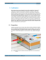
Introduction
1 Introduction
Abstract
This application note shows how to remote control an external R&S®OSP directly from
a Vector Network Analyzer (VNA) or from a Spectrum Analyzer (SA), for instance from
the R&S®ZVA , R&S®ZVB, R&S®ZNB or R&S®FSW families. The application note
describes the requirements and the setup procedure. It is shown how to install the software and how to setup the system in order to get highest flexibility and best usability. It
is additionally shown how to calibrate the entire configuration and finally some practical
examples are provided.The application note mainly addresses the use of VNAs,
appendix 5.4 provides hints regarding the differences when using SAs in a similar way.
Motivation
Vector Network Analyzers (VNA) are the most flexible instruments in RF test and measurement applications. Combining generators and receivers in one single box, additionally they work in a wide frequency range at various bandwidths. Because of their
capability of fast and precise data processing, needed to calculate s-parameters, they
also have a powerful computer inside. Beyond the task of internal data processing this
computer can also be used to control external equipment. This application note shows
how to remote control an Rohde & Schwarz Open Switch and Control Platform (OSP)
directly from a Vector Network Analyzer.
The combination of network analyzers and external switch matrices like the OSP
increases the flexibility in terms of RF test applications. For instance, multiple test
objects can be connected simultaneously and can be tested automatically without
manual interaction. Complex digitally controlled RF modules can be switched into their
specific operating modes while measuring RF parameters for each operation condition.
Prototypes from the RF lab can be connected simultaneously while automatically comparing the RF parameters. There are hundreds of further applications for the combination of network analyzers and external switch and control units.
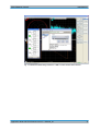
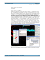
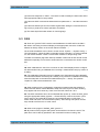
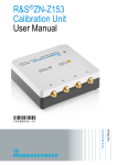
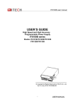
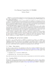
Once installed, the OSP panel software can be directly started and operated on a VNA
as indicated in Fig. 1-1. Now the OSP switch matrix can be set while the effects of the
switching can be simultaneously observed at the VNA. When the switching yields
results suitable for later use, the entire switching configuration can be stored permanently. Using so called "paths" with appropriate "pathnames", for instance "Path_1",
"Path_2",..., each switching configuration can be retrieved by a simple click on one of
the softkeys shown at the right on VNA screen. The OSP panel software can be closed
as soon as all paths are defined and stored. From now each path previously defined
can be directly activated using a single click on the appropriate softkeys at the right.
When the solution of OSP remote control via VNAs was used, it became clear that a
similiar solution is useful for a Spectrum Analyzer (SA) also. Especially when performing 2-port analysis by means of a tracking generator it can be useful to switch RF paths
or to modify DC bias values using digital outputs for instance of a varactor diode in
order to investigate the changes of its RF behaviour. Therefore the OSP remote control
feature is included also for Spectrum Analyzers. Details are described in chapter 5.4 .
Application Note OSP ZVx Remote control ─ 1MA226_0e
3
Direct Remote Control
Introduction
Fig. 1-1: OSP Panel Software being installed on a VNA to control external switch matrices
Application Note OSP ZVx Remote control ─ 1MA226_0e
4
Direct Remote Control
Preparation
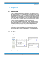
Requirements
2 Preparation
2.1 Requirements
In order to setup this application a vector network analyzer (VNA) either from the ZVA-,
ZVB- or ZNB-familiy is needed along with at least one unit from the OSP family. The
OSP can be equipped with any of its switching options. This application properly works
with OSP Firmware Release 2.42 (and up) and OSP Panel Software Version 2.33 (and
up). Both versions are available at www.rohde-schwarz.com for free. When versions of
the OSP Panel Software are downloaded, the OSP firmware should also be upgraded.
This can be easily done as described in the OSP manual [7], refer to chapter 5.5, "References" .
In addition to the OSP Panel Software two supplemental programs "SetPath_OSP.EXE" and "LoadStat.EXE" are provided. "SetPath_OSP.EXE" is used for
remote controlled path switching. For calibration and convenient VNA remote control
the software "LoadStat.EXE" is needed. Both programs can be downloaded from
www.rohde-schwarz.com together with this application note. The programs "SetPath_OSP.EXE" and "LoadStat.EXE" are described in detail in the appendix of this
document.
Finally it has to be stressed that an additional PC is not needed for this application,
because the OSP is directly remote controlled via the VNA. However, an external PC
can be used, see FAQ section of this document.
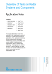
2.2 File Setup
File Organisation
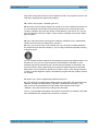
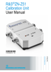
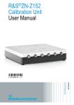
Fig. 2-1: Harddisk file organisation for OSP remote control via VNA
Application Note OSP ZVx Remote control ─ 1MA226_0e
5
Direct Remote Control
Preparation
File Setup
As indicated in Fig. 2-1 the "External Tools" softkeys of the VNA are determined by the
contents of the "External Tool" folder of the VNA's harddisk. Each script file entry in the
"External Tool" folder results in an softkey labelled with the name of the script file, as
shown in box A of the figure above. When pressing the softkey the appropriate file will
be started. When pressing for instance the softkey with the name "Path_2.vbs" the program "Path_2.vbs" will be started.The name of a softkey is determined by exactly one
file in the "...ExternalTools" folder of the VNA. Each softkey represents exactly one file
and vice versa. Therefore the "External Tools" path, as indicated in box A, must only
include command files (.bat, .vbs) according the softkeys to be displayed. For this reason all supplemental files needed to run a program, like EXE, help-file, icons and so
on, have to be stored in different folders outside "ExternalTools" as indicated with box
B and C in Fig. 2-1 . The OSP Panel software is installed in the folder "C:\OSP_Panel",
box B. In order to avoid mixing up both programs, the "SetPath_OSP.EXE" program is
installed in a different folder . This is shown in box C in Fig. 2-1. All VNA path names
can be found above the dashed line in each box. To summarize the organisation,
another example is given: When pressing softkey "Path_3.vbs" the appropriate file
"Path_3.vbs" in the "External Tools" path is started , box A. "Path_3.vbs" itself is starting "SetPath_OSP.EXE" in the path "...\OSP_RemCon\" as indicated in box C.
Installation
Installation is performed in following steps :
●
Download OSP panel software and install it into the "C:\OSP_Panel\" folder,
according Fig. 2-1, box B
●
Recommended: Perform firmware upgrade of OSP
●
Store programs "SetPath_OSP.EXE" and "LoadStat.EXE" in the
folder "... OSP_RemCon\"
●
Files "Path_1.vbs" ... "Path_4.vbs" and "OSP_Panel.bat" have to be stored in the
"External Tools" folder as indicated in box A of figure above
●
the new softkeys should appear on the VNA display now, when following the VNA
menue "System" --> "External Tools"
●
If there are already other "External Tools" installed on VNA it can be necessary to
press the " -- Moore --" button at the bottom of the softkey column in order to see
the four new softkeys
The files "Path_1.vbs" ... "Path_4.vbs" and "OSP_Panel.bat" are also provided and
downloaded along with this application note.
Application Note OSP ZVx Remote control ─ 1MA226_0e
6
Direct Remote Control
Preparation
Easy Operation
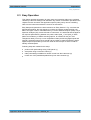
2.3 Easy Operation
This chapter provides information for easy setup and operation without any overhead
caused by instrument settings and calibration. By means of information provided in this
chapter the user can switch the application specific paths just by remote controlling
OSP from the instrument without the need of an external PC.
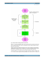
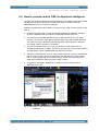
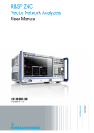
Easy Setup and Operation are both referred to as "Easy Session" .Fig. 2-2 shows the
appropriate workflow, the step sequence numbers in brackets equate the blue numbers in the figure. OSP is controlled either by a Vector Network Analyzer (VNA) or by a
Spectrum Analyzer (SA), herein referred to "instrument". It is assumed that the application requires path switching between two paths, called "path_1" and "path_2". Both
paths can include any of OSP's switching options, for instance B-101 (6 x coax
changeover relais), B-102 (2 x coax multiposition relais) and B-103 (digital inputs and
outputs). Switching options B-101 and B-102 are useful to create RF switching paths.
Digital outputs as provided by B-103 are useful to switch lamps or LEDs in order to
identifiy switched paths.
Following steps are needed for the setup:
●
perform OSP path settings using "OSP panel" (1)
●
save paths using a mnemonic name (2)
●
make path settings available for remote control from the instrument (3)
●
invoke one of the predefined paths directly from the instrument (4)
Application Note OSP ZVx Remote control ─ 1MA226_0e
7
Direct Remote Control
Preparation
Easy Operation
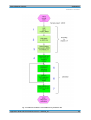
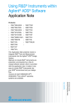
Fig. 2-2: Easy workflow including preparation and operation
Steps 1 to 3 are the preparation which has to be done just once. Step 4 is the invocation of a specific path. Step 4 has to be repeated in order to switch between various
paths previously defined.
Using the OSP panel software the paths have to be set according to the application
requirements as shown in item 1 of figure 2-2. If a device under test (DUT) is connected to OSP, the switching results can be directly observed at the instrument.
The path definition can be saved using OSP panel software according to step 2 in fig.
2-2. In order to make the path switching available to the instrument user, a VBS file is
Application Note OSP ZVx Remote control ─ 1MA226_0e
8
Direct Remote Control
Preparation
Standard Setup and Operation
used. In the example of switching between the paths "path_1" and "path_2" following
two VBS files have to be created:
Finally both files have to be stored as "path_1.vbs" and "path_2.vbs" to the "ExternalTools" directory of the VNA in order to make it visible as softkeys. Refer also to step 3
in fig. 2-2. From now switching between "path_1" and "path_2" can be performed by
simply pressing the appropriate softkey on the VNA, according to step 4 of fig. 2-2.
Don't enter the grey shaded line numbers at the beginning of the text when creating the
files from the scratch, they are for documentation purpose only. See paragraph
"Assigning the path and the channel setup ..." on page 11 for details on VBS files.
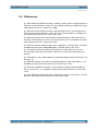
The next chapter describes how to perform the setup similar as described in this chapter, but additionally taking into account instrument settings. Calibration is addressed in
chapter 3 of this document.
2.4 Standard Setup and Operation
After the file setup, the operation setup along with the external remote controlled OSP
can start. This is divided into three independent steps :
(1) defining the paths using OSP_panel software for storing the path configuration
(2) VNA channel setup, eg. frequency, power, bandwidth, number of points
(3) Assigning the path and the channel setup to a VNA softkey
These steps are made for each single measurement of your test suite.
Defining the paths
This step only has to be done once. Later when the paths are defined, this step is not
needed anymore unless the path configuration, i.e. the external switching, has to be
changed or new paths have to be created. For this purpose the OSP Panel Software
(OSP_PS) will be started. With exception of the program storage path there is no difference in using the OSP_PS on a VNA, as in our case, or on a PC as commonly
done. The best documentation on how to operate the OSP_PS is given in [7], see References in chapter 5.5 After having started the OSP_PS a network address is needed.
If the OSP is directly connected to the VNA via LAN without any DHCP-Router the
address is normally
Application Note OSP ZVx Remote control ─ 1MA226_0e
9
Direct Remote Control
Preparation
Standard Setup and Operation
"TCPIP::192.168.48.147::INSTR"
The address
"TCPIP::192.168.0.146::INSTR"
can also be possible. The remote control address is shown on a display connected to
OSP. The address changes to green color in OSP_PS if the connection was successfull. From now all switches can be operated depending on the options installed in OSP.
It is useful, to do all the cabling from/to the VNA and the DUTs now. If possible, it is
also useful to connect the DUTs, at least a subset. Now all switching can be done
manually using OSP_PS.The VNA settings can be made in parallel in order to optimize
the test configuration. If the results are adequate the settings can be saved in the VNA
as well as in OSP. On the VNA the settings will be saved as *.zvx files. It will be needed later for calibration as described in chapter 3 of this document. The OSP paths are
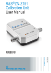
saved by names directly in the OSP instrument. Don't forget to set the green check
marks in OSP in order to take the switch into account when defining the path, see Fig.
2-3. No extensions are needed for the path names in OSP. It is a good practice to use
the same name for the VNA zvx file and the OSP path name. After having defined the
paths, the OSP Panel Software is no longer needed and can be closed.
Fig. 2-3: Green check marks have to be set to include the relais into the path definition (red arrows)
Application Note OSP ZVx Remote control ─ 1MA226_0e
10
Direct Remote Control
Preparation
Standard Setup and Operation
VNA channel setting up
In the next step the VNA channel settings, ex. frequency, power, bandwidth and number of points have to be made and have to be stored on the VNA using a file name
extension ".zvx". The .zvx file should also have the same name as the path names
mentioned above. For instance when setting up a filter test using a low pass filter as
DUT the name FILTER_LP_00 is useful. The OSP path name "FILTER_LP_00" shall
be used along with the VNA file "FILTER_LP_00.zvx". It is recommended to use
upper-/lowercase letters A...Z and decimal numbers 0...9 and the underscore "_" only
within names. All other signs especially "space" characters have to be avoided.
For a first approach it is useful to use the standard path names "Path_1" , "Path_2", ...
because it is much easier to prepare the appropriate softkeys. In a second step it is
possible to use additional names which are more comprehensive according to the
application.
When optimizing the path switching of OSP and the VNA setup, it is useful to have the
OSP Panel window downsized in a display corner of the VNA and to enlarge it when
some switches or path definitions have to be changed.
Assigning the path and the channel setup to a VNA softkey
Previously defined path configurations shall be directly invoked by a softkey, for
instance "Path_1" ... "Path_4". For this purpose a so called Visual Basic Script (VBS)
file has to be created or can be downloaded with the Application Note. VBS is a standard format supported by Windows versions starting from Windows XP , Windows 7 and
8 included. The VBS file is a standard text file which can be edited using any standard
text editor, for instance Windows Notepad. Using the single quote character ' comments can be written into the vbs file. The file should be of type ".vbs" and must be
stored in the "External Tools" folder of the VNA, refer to fig. 2-1 above for details.
Chapter "Reference Example" of this document provides some examples vbs files.
The VNA display looks as shown in the figure below with the External Tools softkeys
( via the menu "System" --> "External Tools").
Application Note OSP ZVx Remote control ─ 1MA226_0e
11
Direct Remote Control
Preparation
Standard Setup and Operation
Fig. 2-4: Previously defined paths now can be directly invoked using the softkeys at the right
The control setup can be easily tested by pressing the "Path..." softkeys one after each
other. If the environment is not too noisy one can hear the relais switching within OSP
when pressing one of the softkeys. If the path switching does not work in the expected
way, following two items have to be checked first :
(1) OSP remote address correct ?
(2) is the path name exactly the same as previously defined ?
The OSP remote address must be the same as entered in the OSP panel software.
The "SetPath_OSP.EXE" program is checking carefully whether proper pathnames are
used as previously stored in OSP. If a path is not available when invoking "SetPath_OSP.EXE" an appropriate error message will be generated. Refer to further hints
on this in chapter 5.1.
Application Note OSP ZVx Remote control ─ 1MA226_0e
12
Direct Remote Control
Calibration
Preparation
3 Calibration
Each measurement of your test suite has its own path configuration. Thus for each
measurement an appropriate calibration is required. According to the calibration
requirements of the VNA, channel specific parameters as frequency range, power,
bandwidth and number of points and so on need to be defined before a calibration is
started. Therefore the setup of the VNA and the external path switching via OSP has to
be done before starting the calibration. It is a good practice to use the same name for
the OSP path and the appropriate VNA setup file, i.e. the .zvx file. Therefore the name
of the calibration storage file is already available from the operation setup as created
and stored along with the OSP path definition. Before beginning calibration the apporopriate zvx configuration file needs to be reloaded. Up to now the zvx configuration file
doesn't have any calibration information, which will be added along with the upcoming
calibration now. Finally it will be stored using the same name. When invoking the OSP
path via a VNA softkey the VNA setup along with calibration data are reloaded simultaneously as described in the upcoming text.
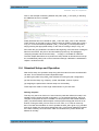
3.1 Preparation
Calibration standards such as Through, Open, Match and Short (TOSM) are available
as a set of calibration standards according to the connector system in use. For each of
the four calibration steps, the calibration reference has to be manually connected. For
an automatic calibration the ZV-Z5x devices are available. The calibration process for
the remote controlled OSP application is the same as for every standard VNA application.
Fig. 3-1: USB remote controlled cal standards of the ZV-Z5x family reduce cal time and efforts dramatically
Application Note OSP ZVx Remote control ─ 1MA226_0e
13
Direct Remote Control
Calibration
Calibration workflow
The ZV-Z5x devices are available either in 2-port or 4-port versions. When a cal standard either as manually operated cal kit or as automatic switchable device is available,
the next step of calibration can begin.
3.2 Calibration workflow
Figure 3-2 shows the calibration workflow using the test project "ABCD", which in this
paragraph will be used for all file names along with setup and calibration. The OSP
path switching and VNA setup are already defined and assigned to a softkey, steps 1,
2 and 3. Pressing the appropriate softkey the VNA and OSP settings are reloaded
now, step 4. Now additional cables have to be connected to the OSP up to the "reference points", step 5, where the calibration standards will be connected to. Now calibration can be started using the standard calibration function of the VNA, steps 5 and 6,
for instance 2-port TOSM as described in [8] and [9] and shown in a video [4].
Replacement of the cal standard according to TOSM is needed until the calibration is
completed. Finally the .zvx file has to be restored, including calibration data now,
step 7.
Application Note OSP ZVx Remote control ─ 1MA226_0e
14
Direct Remote Control
Calibration
Calibration workflow
Fig. 3-2: Calibration workflow to extend ABCD.zvx by calibration data
Application Note OSP ZVx Remote control ─ 1MA226_0e
15
Direct Remote Control
Reference Example
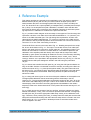
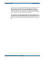
4 Reference Example
This chapter provides one example for this application note. The goal is to test three
different devices (DUTs) with one two port vector network analyzer (VNA) and to
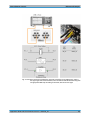
switch between the DUTs and the appropriate VNA setups by means of softkey buttons. The three DUTs are a quarz (8 MHz), a bandpass filter (~430 MHz) and an amplifier (1 GHz). For the amplifier a full path calibration is needed in order that the reference plane is directly at the connectors of the amplifier. Because of their lower operating frequencies no calibration is needed for the quarz and the filter.
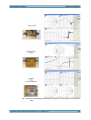
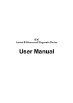
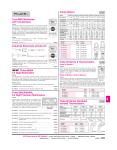
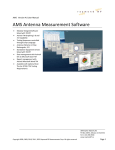
Fig. 4-1 provides a block diagram of the test setup in the upper left. The left orange line
represents a 50 Ohm coax cable which links OSP-B102/Relais K1, "C" (common) connector to the VNA transmitter port. The right orange line represents a 50 Ohm coax
cable which links OSP-B102/Relais K2, "C" (common) connector to the VNA receiver
port. Relais K1 and K2 provide 6 positions each.Each Relais can connect the common
connector "C" to one of the surrounding connectors.
The three DUTs are shown in the lower left of Fig. 4-1. Reading example for the amplifier, shown at the bottom of Fig. 4-1: The input is connected via blue coax cable (see
photo in the upper right) to connector 3 of OSP relais K1. The amplifier's output is connected via coax cable to connector 3 of OSP relais K2. The reference planes for the
calibration of the amplifier paths are directly at the input and the output of the DUT,
indicated by green points, thus taking all cables into account. The VNA setup including
calibration data is stored in the file using the arbitrary name " reteid_3.zvx", where
"reteid_3" without .zvx is specified in the appropriate vbs file only, see Fig. 4-4. For the
amplifier test the OSP path settings are stored in the OSP using the path name
"db_03".
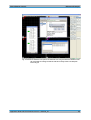
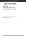
Fig. 4-2 shows how to define the OSP path "db_02" using the OSP panel software running on the VNA. Position 2 is selected for relais K1 and K2, according to the filter connections as shown in Fig. 4-1, photo (brown/yellow cable). The green buttons K1 and
K2 shown in Fig. 4-2 indicate, that the appropriate relais is belonging to the path definition, they are therefore both activated. After being defined, the path can directly be
stored in the OSP.
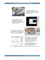
Fig. 4-3 along with its text gives an overview of the path calibration of the amplifier test.
The appropriate calibration data is stored along with the VNA setup in the file
"reteid_3.zvx". The successfull calibration can be easily verified by the "CAL" id on the
VNA screen and additionally by the open / match / short results as shown in the Smith
Chart display of the VNA when connecting appropriate cal standards to the cable's
endpoints. Refer to the Smith Chart shown on the poster "Microwave and beyond", reference [5].
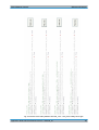
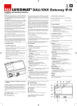
Fig. 4-4 finally shows the contents of the four vbs-files, which are called by the VNA's
external tool softkeys. "Path_2.vbs" for instance represents the filter test. The appropriate OSP path "db_02" and the appropriate VNA setup "reteid_02" are defined accordingly. Therefore, when pressing the "Path_2" softkey button the OSP path and the VNA
setup will both be activated along with the instrument setup which is stored in the VNA
setup "reteid_02". Fig. 4-4 is shown in landscape format to avoid line breaks which
must not appear in vbs files.
Application Note OSP ZVx Remote control ─ 1MA226_0e
16
Direct Remote Control
Reference Example
In order to provide more convenience to operate the whole configuration, the four vbs
files "Path_1.vbs", "Path_2.vbs", "Path_3.vbs" and "Path_4.vbs" can be easily
renamed to more intuitive names.In our example it would be useful to rename it to
"Qrz_test.vbs", "BpF_test.vbs", "Amp_test.vbs" and "unused.vbs"". After renaming
using Windows Explorer, the new names will also appear on the softkeys making it
much easier to operate the whole configuration. If the file "unused.vbs" will be deleted
from the "External Tools" folder, the entire softkey disappears.
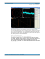
Fig. 4-5 finally shows the results. When pressing the red marked softkey at the right,
the appropriate DUT will be activated and tested. The VNA display will change accordingly. After the first new complete VNA sweep the test results are stable and are shown
on the screen of the VNA. Calibration was just done for the amplifier test in this example. For sure it can be done for all other DUTs and the appropriate paths in the same
way.
Application Note OSP ZVx Remote control ─ 1MA226_0e
17
Direct Remote Control
Reference Example
Fig. 4-1: The figure shows the block diagram, upper left, connections to the OSP K1-Port, photo in
the upper right, DUTs and connections, lower left and the OSP PATH names along with
the appropriate VNA setup according to each DUT, table in the lower right.
Application Note OSP ZVx Remote control ─ 1MA226_0e
18
Direct Remote Control
Reference Example
Fig. 4-2: Shows the definition of the path for the band filter test using the OSP Panel Software installed on the VNA. The settings of OSPs K1 and K2 are finally stored in the OSP path
named "db_02"
Application Note OSP ZVx Remote control ─ 1MA226_0e
19
Direct Remote Control
Reference Example
Fig. 4-3: Summary of calibration which includes the whole path from the VNA ports directly up to the
DUT.
Application Note OSP ZVx Remote control ─ 1MA226_0e
20
Direct Remote Control
Reference Example
Fig. 4-4: Contents ot the softkey definition files Path_1.vbs ... Path_4.vbs. Softkeys at the right.
Application Note OSP ZVx Remote control ─ 1MA226_0e
21
Direct Remote Control
Reference Example
Fig. 4-5: Results are immediately displayed when pressing the red marked softkeys at the right of the
VNA
Application Note OSP ZVx Remote control ─ 1MA226_0e
22
Direct Remote Control
Appendix
Documentation of "SetPath_OSP.EXE"
5 Appendix
This paragraph provides useful information if something is not working as expected.
5.1 Documentation of "SetPath_OSP.EXE"
Using the software "SetPath_OSP.EXE", the predefined paths of OSP can be
switched. The software "SetPath_OSP.EXE" is herein referred to as "software" in
short. The software needs at least two parameters which both have to be specified
before starting.
Parameter_1 is the remote control address of the OSP. For example "TCPIP::
10.110.10.253::INSTR" starts with the letters "TCPIP", indicating that the instrument is
remote controlled via LAN, followed by the LAN address (10.110.10.44) and terminated
by "::INSTR". The termination "::INSTR" must always be provided . The letters "TCPIP"
have to be replaced by "GPIB" when using a GPIB remote control interface. The
address info depends on the instrument.
Valid example for parameter_1 using LAN:
TCPIP::10.110.10.253::INSTR
Valid example for parameter_1 using GPIB: GPIB::20::INSTR
On OSP the remote control address will be dislayed when connecting an external monitor.
Parameter_2 is the name of the OSP path to be switched. The OSP path name must
start with a letter A-Z and can include numbers between 0 and 9, additionally the
underscore "_" character is allowed to be used in OSP pathnames.Other characters
especially dots, commas, spaces are not allowed to be used within OSP path names.
Figure 4-4 provides an example how to invoke "SetPath_OSP.EXE" along with proper
OSP pathnames.
In order to install the software the appropriate file "SetPath_OSP.EXE" has to be copied to a path on the harddisk of the instrument as shown if figure 2-1 above. The user
must have write access to the selected path. This is normally the case in the "user"
area on the harddiks of the instrument.
The software performs a careful check whether the specified OSP path is defined in
OSP. The software generates an appropriate message, if the specified OSP path can't
be find in OSP. However, for the sake of convenience all outputs from the software are
omitted under normal operating conditions. In order to display the output from the software an additional parameter has to be specified when invoking the software, as following example shows :
SetPath_OSP.EXE TCPIP::10.110.10.253::INSTR path_A 128
The third parameter "128" is a numeric code informing the software to display some
kind of debug information which can be useful if the entire configuration does not work
as expected. The screenshot below shows an example of an appropriate output.
Application Note OSP ZVx Remote control ─ 1MA226_0e
23
Direct Remote Control
Appendix
Documentation of "SetPath_OSP.EXE"
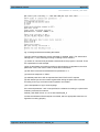
Fig. 5-1: Debug information from SetPath_OSP software
The very first line provides the version message of "SetPath_OSP". The areas below
starting with "**" have following meaning according to their numbers :
(1) number of command line parameters detected when the program is invoked. There
are 3 parameters in this example.
(2) list of parameters accounted according to their sequence of appearance, the third
parameter "128" is the code in order to show all this information.
(3) OSP SCPI command as assembled from parameter nr. 2
(4) instrument response to "*IDN?"
(5) available paths from OSP as reported from ROUT:PATH:CAT? request
(6) OSP status byte and error status register after writing the path close command
according to item (3), both zeros means operation successfull
(7) the interpretation of (6) in clear language
If the second parameter "128" is not specified, the software is working in a quiet mode.
Following command for instance
SetPath_OSP.EXE TCPIP::10.110.10.253::INSTR path_A
invokes the software while all outputs are omitted, which is appropriate when the configuration is working properly.
Application Note OSP ZVx Remote control ─ 1MA226_0e
24
Direct Remote Control
Appendix
Documentation of "LoadStat.EXE"
5.2 Documentation of "LoadStat.EXE"
Using the software "LoadStat.EXE", a predefined instrument setup can be reloaded.
The software can be operated along with ZVxx series of VNAs and with spectrum analyzers of the FSW series. The instrument is automatically detected by means of the
response send by the "*IDN?" request. The impact of LoadStat is equal to reloading a
setup files via the front panel of the instrument. For VNAs the setup can also include
calibration data. The software "LoadStat.EXE"is hereinafter referred to as "software" in
short. The software needs at least one parameter which has to be specified before
starting.
Parameter_1 is the body of the setup file where the settings are stored. The file type is
detected automatically according to the instrument type. Therefore the extension must
not be specified, i.e. the name must n o t include a point. For example when the setup
has been stored using the name ABCD the software invocation is as follows :
LoadStat.EXE ABCD
Similar as described above a second parameter, Parameter_2, can be specified. If it is
set to "128" a set of diagnostic information is provided being useful if the configuration
doesn't work as expected. The figure below shows an example of the output.
By means of a third parameter, Parameter_3, a remote control address can be specified which is used when the remote control is performed using an external PC. If
Parameter_3 is not specified, the address used is always "TCPIP::LOCALHOST::INSTR", which applies when the instrument is controlled internally.
Complete invocation example:
LoadStat.EXE reteid_02 128 TCPIP::10.110.10.144::INSTR
The very first line provides the version message of "LoadStat". The areas below starting with "**" have following meaning according to their numbers :
(1) number of command line parameters detected when the program is invoked. There
are 3 parameters in this example.
(2) list of parameters accounted according to their sequence of appearance, the second parameter "128" is the debug code in order to show all this information.
Application Note OSP ZVx Remote control ─ 1MA226_0e
25
Direct Remote Control
Appendix
FAQ
(3) instrument response to "*IDN?". The result is used to identify the instrument and to
send appropriate calls for setup reload.
(4) Instrument SCPI command as assembled from parameter nr. 1 and the instrument
type
(5) Instrument status byte and error status register after writing the command according to item (4), both zeros means operation successfull
(6) The status byte information written in clear language
5.3 FAQ
Q1: How can I get the TCPIP remote control addresses for OSP and for the VNA ?
A1: When connecting an external display to the appropriate connector of OSP the
address is directly shown on the screen behind "Address: ...".
On the VNA the address can be shown via the menue "System --> System Config -->
LXI Configuration". When the VNA is internally remote controlled, i.e. without external
PC, the remote address "TCPIP::LOCALHOST::INSTR" is always being used.
The R&S Commander (App-Note 1MA74) software is also usful to find remote control
addresses especially if more tha two instruments are connected to the remote control
bus.
--Q2: After callibration the CAL ID is not shown on the VNA's display and the configuration behaves like being uncalibrated when invoking a measurement setup by means of
a softkey.
A2: The calibration information has to be added to the VNA setup file after calibration.
You should first load a VNA setup via a softkey, then perform the calibration and finally
write the setup back to the same file loaded before (File --> Save). The question
"replace it" need to be answered with "Yes".
--Q3: After powering up the configuration it happens sometimes that the softkeys to
switch the OSP and to reload calibration setup don't work anymore. When invoking,
they appear and I don't hear any "clack" from the OSP. What can I do ?
A3: The OSP sometimes has to be re-initialized after power up. Invole the OSP_panel
using the appropriate softkey (System --> ExternalTools), make a connection ("Connect to device") and manually activate one of the defined paths in OSP (Path -->
Switch Path and switch one of the defined paths). After leaving OSP panel, the softkeys should work if there is no other cause.
--Q4: What is the program "SetPath_OSP" good for ?
A4: By means of this program OSP paths can be switched via remote control. The
path name can be directly specified in the command line when invoking "Set-
Application Note OSP ZVx Remote control ─ 1MA226_0e
26
Direct Remote Control
Appendix
FAQ
Path_OSP" along with the remote control address of OSP. The program is used on the
VNA when switching OSP paths using softkeys.
--Q5:: What is the program "LoadStat" good for ?
A5: By means of this program setups from a VNA or SA can be loaded via remote control. The setup file to be loaded can be directly specified in the command line when
invoking "LoadStat" along with the remote control address of the VNA or SA. The program is especially used on the VNA in order to restore calibration values when switching OSP paths.
--Q6: Can I start and test the both programs "SetPath_OSP.EXE" and "LoadStat.EXE"
outside the environment of softkeys and .vbs files ?
A6: Yes, you can do it either via an external PC or by connecting a USB keyboard to
the VNA and use its internal controller. If you are using a Windows keyboard including
a Windows button
you can activate the Start Window by simultaneously pressing the Windows button and
the letter "R". Now you can enter the program name SetPath_OSP.EXE or LoadStat.EXE respectively followed by the command line parameters as described in the
previous sections. When pressing OK the program will start along with the specified
parameters. For this interactive operation it is useful to set the "128" debug parameter
in order to get the diagnostic outputs, otherwise the program will work "silently" without
any outputs.
--Q7: Where can I get the supplemental software tools from ?
A7: The entire set of supplemental software tools are attached to the Application Note
1MA226. Therefore the files SetPath_OSP.EXE, LoadStat.EXE, and Path_1.vbs ...
Path_4.vbs can be downloaded from http://www.rohde-schwarz, search topic
"1MA226 , along with the pdf file according to this document.
The C++ sources (MS Visual Studio and DevCPP environment) for SetPath_OSP.EXE
and LoadStat.EXE are available from the author on request.
Application Note OSP ZVx Remote control ─ 1MA226_0e
27
Direct Remote Control
Appendix
How to remote control OSP via Spectrum Analyzers
5.4 How to remote control OSP via Spectrum Analyzers
The OSP remote control feature so far described for Vector Network Analyzers (VNAs)
can also be used along with Spectrum Analyzers (SAs), for instance from the
R&S®FSW family. Fig. 5-2 shows an example.
Following conditions have to be taken into account when using a SA for remote control
OSP of:
●
Spectrum Analyzers don't provide an inherent calibration as VNAs do. Therefore
no direct calibration data is included in the dataset reloaded from SAs.
●
The extension of reloaded data files is "dfl" for SAs rather than "zvx" for VNAs.
However, the extension must not be specified when using the LoadStat.EXE tool.
The instrument type is detected automatically and the file extension is selected
accordingly. Refer to chapter 5.2 for details.
●
The user accessible directory is "C:\R_S\Instr\user\" for SAs rather than "C:
\Rohde&Schwarz\Nwa" for VNAs. This has to be taken into account when installing
and operating the tools LoadStat.EXE and SetPath_OSP.EXE.
●
SAs don't provide External Tools in order to start programs. However, the Windows
task line can be used in SAs for this purpose. The VBS files have to be created
first. In a second step they can be drawn using a mouse to the SA's task line in
order to be available for direct invocation using a mouse.
●
An external LAN Router / Multiplexer is needed in order to remote control
R&S®OSP from a SA.
Fig. 5-2: Direct remote control of the switch matrix OSP via spectrum analyzer FSW and an external
LAN Router
Application Note OSP ZVx Remote control ─ 1MA226_0e
28
Direct Remote Control
Appendix
References
5.5 References
[1] R&S ZNB Vector Network Analyzer, Leading in speed, dynamic range and ease of
operation, Product Brochure, 05.00, Jan. 2013, PD 5214.5384.12, available from http://
www.rohde-schwarz.com, search topic "ZNB"
[2] R&S ZVA Vector Network Analyzer, High performance up to 110 GHz with up to
four test ports, Product Brochure, 10.00, Aug. 2012, PD 5213.5680.12, available from
http://www.rohde-schwarz.com, search topic "ZVA"
[3] R&S Open Switch and Control Platform, Modular solution for RF switch and control tasks, Product Brochure, 04.02, Jan. 2013, PD 5214.1437.12, available from http://
www.rohde-schwarz.com, search topic "OSP"
[4] R&S ZVA network analyzer basics part 2: Callibration, YouTube Video, 21.2.2012,
available from http://youtu.be/RxwfMKhS4S0 , sampled at Sept. 18th, 2013
[5] Microwave and beyond, (PDF-)Poster English, PD 3606.7582.82, 01.00, Oct.
2012, awailable from http://www.rohde-schwarz.com, search topic "Microwave and
beyond"
[6] Zohrabian R., 2013, VNA Calibrations, Speed Up Multiport, Microwaves & RF, July
2013, pg. 76
[7] R&S Open Switch and Control Unit Operating Manual, 2008, 1505.3896.12 – 09,
available from http://www.rohde-schwarz.com, search topic "OSP"
[8] R&S ZVA / R&S ZVB / R&S ZVT, Vector Network Analyzers Operating Manual,
2013, 1145.1084.12 - 21, available from http://www.rohde-schwarz.com, search topic
"ZVA"
[9] R&S ZNB Vector Network Analyzers User Manual, 2013, 1173.9163.02 - 15, available from http://www.rohde-schwarz.com, search topic "ZNB"
Application Note OSP ZVx Remote control ─ 1MA226_0e
29