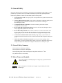
1
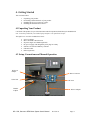
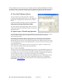
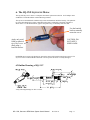
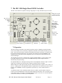
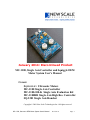
January 2014: Discontinued Product
MC-1100, Single Axis Controller and Squiggle OEM
Motor System User's Manual
Covers:
SQUIGGLE™ Ultrasonic Motors
MC-1100 Single Axis Controller
MC-1100-100-K Single Axis Evaluation Kit
MC-1100HR Single Axis High Res. Controller
SQ-2301 Single Axis Handset
Copyright © 2009 New Scale Technologies Inc. All rights reserved.
MC-1100, SQUIGGLE OEM Motor System User's Manual
Revision A
Page: 1
This page left intentionally blank.
MC-1100, SQUIGGLE Motor System User's Manual
Revision A
Page: 2
Table of Contents
1.
2.
Welcome
General Safety
2.1 General Safety Summary
2.2
Safety Terms and Symbols
2.2.1
These terms may appear in this manual:
3. Contact New Scale Technologies, Inc.
4. Getting Started
4.1
Unpacking Your Product
4.2
Setup, Connections and Manual Operation
4.3
New Scale Pathway Software
4.4
Open-Loop or Closed-Loop Operation
5. The SQL-3.4-10-xx SQUIGGLE Motor
6. The SQ-1XX SQUIGGLE Motor
6.2
Outline Drawing of SQ-115*
7. The MC-1100 Single Board OEM Controller
7.1
Operation
7.2
Controller Connectors
7.2.1
OEM Board Power Connector (J1)
7.2.2
RS-422 Encoder Enable Jumper Connector (J2)
7.2.3
Program and SPI Connector (J3)
7.2.4
RS-422 Encoder and Optional 16-bit ADC Input Connector (J4)
7.2.5
Motor Connection (J5)
7.2.6
External Control Connector (J6)
7.2.7
Handset Connector (J7)
7.2.8
RS232 Connector (J8)
7.3
Analog Servo Control
7.4
Controller Handset
8. Integration Guide
8.1
Other potential issues to be aware of:
9. Specifications Summary
9.1
SQ-1XX Motor
9.2
SQ-2001 Single Axis Handset
10.
MC-1100 Board Schematics
11.
Warranty
MC-1100, SQUIGGLE Motor System User's Manual
Revision A
4
5
5
5
6
7
8
8
8
9
9
10
11
11
12
12
13
13
13
13
14
14
15
15
15
16
17
18
18
19
19
19
20
25
Page: 3
1. Welcome
Thank you and congratulations on your purchase of the SQUIGGLE Motor Evaluation Kit. The kit includes:
•
•
•
•
•
A SQUIGGLE™ motor.
Drive electronics PCB with USB computer control or handset input.
Power and USB cable
5 Volt power supply
Manual handset (optional).
The SQL Series linear motors come in a range of sizes to meet the
needs of markets ranging from small, portable consumer
electronics to high precision instrumentation. The SQUIGGLE
motor is a patented piezoelectric ultrasonic linear motor and is
designed to withstand high shock and a broard temperature range
and yet offer millimeters of stroke, sub-micrometer precision, high
forces, and high efficientcies.
New Scale Technologies is constantly striving to improve the performance of the SQUIGGLE motor and
satisfy the customer’s needs for precise reliable motion. With this in mind, feel free to contact New Scale
Technologies or visit our web site at www.newscaletech.com for the latest updates and exciting
SQUIGGLE™ new
MC-1100, SQUIGGLE Motor System User's Manual
Revision A
Page: 4
2. General Safety
Review the following safety precautions to prevent injury and avoid damage to this product. Use this
product only as specified. Service procedures should only be performed by qualified personnel.
Follow these guidelines to insure safe and reliable operation of this product:
1.
Use Proper Power Cord. Use only the power cord specified for this product and certified for
the country of use.
2.
Connect and Disconnect Properly. Do not connect or disconnect components while power is
on. Unplug the power connection from the back of the unit before connecting or
disconnecting any cables.
3.
Avoid Physical Shocks to the Motor. The motor contains a piezoelectric actuator
susceptible to excessive shock.
4.
Do Not Apply Side Loads the Motor Shaft. Excessive side loads may damage the motor.
Always apply loads parallel to the motor shaft.
5.
Do Not Retract Beyond Limit. Do not allow the motor to overrun its travel limits when
moving backwards. The threaded shaft may disengage from the internal threads. If this
happens gently re-insert the screw until the threads are re-engaged and turning smoothly.
6.
Avoid Contact with Internal Electronic Circuitry. High voltage is present inside the
controller and motor when activated. Do not touch connections and components when power
is on.
7.
Call Us If You Have a Problem or Question. If your system is not operating within
specifications or you have questions please contact us. Our service and support team is eager
to help and will provide instructions for diagnosis and return to our factory for repair.
2.1 General Safety Summary
Do Not Operate in Wet/Damp Conditions.
Do Not Operate in an Explosive Atmosphere.
Do not Operating in the corona vacuum pressure range from 100 Torr to 10-3 Torr.
Keep Product Surfaces Clean and Dry.
2.2 Safety Terms and Symbols
This symbol indicates potentially dangerous voltages may be present when the
motor is operating.
Only use an approved 5 Volt DC power supply or as provided by New Scale
Technologies.
MC-1100, SQUIGGLE OEM Motor System User's Manual
Revision A
Page: 5
2.2.1
These terms may appear in this manual:
WARNING identifies conditions or practices that could result in damage, injury or loss of life.
CAUTION identifies conditions or practices that could result in damage to this product or other
property.
DANGER indicates an injury hazard immediately accessible as you read the marking.
MC-1100, SQUIGGLE Motor System User's Manual
Revision A
Page: 6
3. Contact New Scale Technologies, Inc.
Address
Phone
Fax
Web
Sales
Service
New Scale Technologies, Inc.
121 Victor Heights Parkway
Victor NY, 14564
USA
(585)-924-4450
(585)-924-4468
www.newscaletech.com
[email protected]
[email protected]
MC-1100, SQUIGGLE Motor System User's Manual
Revision A
Page: 7
4. Getting Started
This section describes:
1.
2.
3.
4.
Unpacking your product.
Performing a functional check of your product.
Installing the SQUIGGLE motor on a stage.
Installing the demonstration software.
4.1 Unpacking Your Product
CAUTION: This product is a precision instrument and all components should always be handled with
care. Treat this product like you would a laptop computer or an optical microscope.
The SQL EVALUATION KIT includes these items:
•
•
•
•
•
•
•
SQUIGGLE Motor
MC-1100 OEM Controller PCB
SQ-2301 Single Axis Handset(optional)
DC power supply with changeable power plug for country
Software CD with NST Pathways software
USB mini cable
RS232 (Optional)
4.2 Setup, Connections and Manual Operation
DC Power
Adapter
Motor Connector
USB Cable
MC1100
Handset
Adapter
RS-232 Adapter
Make these connections to the MC-1100 OEM Controller.
MC-1100, SQUIGGLE OEM Motor System User's Manual
Revision A
Page: 8
If using a handset, the SQUIGGLE motor may be manually operated by pushing and holding the JOG FWD
or JOG REV buttons on the Handset and adjust speed by rotating the speed knob. Releasing the button will
stop the motor. Note, the SQL series motors require a minimum 10-15 gram preload to move the shaft.
4.3 New Scale Pathway Software
The control software provided with the MC-1100 Motor
Controller enables point-and-click control via a PC USB port. It
also includes a scripting interface and an ActiveX command
library.
Each MC-1100 Motor Controller can operate one SQUIGGLE
motor, and you can manage multiple motor controllers
simultaneously from a single control software window.
The control software and scripting interface allow you to easily
evaluate open-loop and closed-loop performance of SQL Series
SQUIGGLE motors.
4.4 Open-Loop or Closed-Loop Operation
We recommend closed-loop operation when repeatable step size, absolute position or precise velocity
control is needed. The MC-1100 accepts input from remote position sensors or switches for
closed-loop motion control.
With a digital (incremental) encoder as a position sensor, the resolution of the encoder determines
closed-loop position resolution. With an analog position sensor, closed-loop position resolution is
determined by the A/D converter, the resolution of the position sensor, and the resolution of the motor.
For more information see the New Scale Application Note: Creating Closed-Loop Positioning Systems
Using SQUIGGLE Motors.
In open-loop mode, you can calibrate a motor’s average step size in response to a number of drive
pulses. Open-loop resolution is listed on the motor data sheets.
MC-1100 with the TRACKER™
The MC-1100 can be used with the TRACKER™ Position Sensor. The TRACKER™ position sensor
is a magnetic sensor array with integrated on-chip digital encoding. With 0.5 micron resolution and
size as small as 3.9 x 2.5 mm, it is a robust, cost-effective alternative to miniature optical encoders for
non-contact position sensing. See Tracker quick start guide for more information.
On-chip encoding provides direct digital output using standard I2C protocol, eliminating the need for
external pulse counters. Efficient control system communications allows up to two TRACKER
position sensors on a single I2C bus. (Custom position sensors with SPI and A quad B interface are
also available; contact the factory.)
MC-1100, SQUIGGLE Motor System User's Manual
Revision A
Page: 9
5. The SQL-3.4-10-xx SQUIGGLE Motor
The SQUIGGLE threaded shaft simultaneously rotates and translates inside the housing. The spherical
tip of the shaft should press against a hard flat surface that is orthogonal to the shaft centerline as
shown below. For detailed mounting instructions, see the Integration Guide for SQL-3.4-10 Motors.
CAUTION: The SQUIGGLE motor contains HIGH VOLTAGE. Be careful of
exposed connections on adapter cable.
Apply only axial loads
to spherical tip of
SQUIGGLE.
Figure 5-1 SQL 3.4-10 Dimensions and FPC Pin Out
MC-1100, SQUIGGLE OEM Motor System User's Manual
Revision A
Page: 10
6. The SQ-1XX SQUIGGLE Motor
The SQ-1XX SQUIGGLE motor is a complete micrometer replacement solution. It will adapt to most
standard 0.375 inch threaded or non-threaded stage mounts.
The SQUIGGLE threaded shaft simultaneously rotates and translates inside the housing. The spherical
tip of the shaft should press against a hard flat surface that is orthogonal to the shaft centerline as
shown below. Use the knurled knob, opposite the spherical tip, to manually rotate the shaft.
Use the knurled
knob to manually
rotate the screw.
CAUTION: DO
NOT APPLY
SIDE LOADS.
Apply only axial
loads to spherical
tip of SQUIGGLE
shaft using a
hard flat surface.
DANGER: Do not remove the housing or operate the motor with internal connections exposed. The
SQUIGGLE motor contains HIGH VOLTAGE. Do not operate the motor if visually damaged.
6.2 Outline Drawing of SQ-115*
*Only shaft length change for other versions.
MC-1100, SQUIGGLE OEM Motor System User's Manual
Revision A
Page: 11
7. The MC-1100 Single Board OEM Controller
The MC-1100 Controller is capable of driving a single SQL-3.4 or SQ-1XX Series SQUIGGLE motor.
Note: The Forward
and Reverse Limit
lines are active low.
J1: 4.5V-5.5V
DC Supply
ONLY
GND
J11: USB
J5:
Motor Phase1
Motor GND
Motor Phase2
INTLK (if used)
Fwd Limit
Rev Limit
Limit GND
VLogic
J7: RS-485
Connection
to Handset
J4: RS-422
and Opt. 16-bit
ADC Input
J8: Connects To
RS232 Adapter
J6: Analog Input
and Digital I/O
J3: JTAG and
SPI Inputs
J2: RS-422
Enable Jumpers
7.1 Operation
The basic principles of the MC-1100 controller operation consist of a digitally controlled resonant
circuit. The resonant circuit is formed by components in the MC-1100 Controller and the SQUIGGLE
motor. This electrical resonance is tuned to the mechanical resonance of the motor. Each motor type
has operating parameters that the MC-1100 controller will read from its internal EEPROM. This
information is set at the factory and is changeable by the user with specific instructions from New
Scale Technologies.
The controller may generate a continuous drive signal (Amplitude Mode) or a series of drive signal
bursts (Burst Mode) to the motor based on the EEPROM settings and the amplitude/duration
determined by the Speed setting.
In Amplitude Mode, the % Max Speed setting referrers to the amplitude of the drive signal. The drive
signal itself is continuous (at the motor drive frequency) while the motor is running.
In Burst Mode, the % Max Speed setting referrers to duration that the drive signal is active within a 10
msec (i.e. 100Hz) period. The amplitude of the drive signal in this case is taken from a preset value in
the MC-1100’s EEPROM. The drive signal burst is repeated every 10 msec while the motor is
running.
A combination mode is also available that allows the user to define a specific number of bursts to
perform, the period and duration of each burst and the amplitude of the burst. This is referred to as the
“Step Control” in the user interface of the demonstration program. Note, however, the actual distance
moved with each burst (or timed step) is load dependent.
MC-1100, SQUIGGLE Motor System User's Manual
Revision A
Page: 12
LED operation:
•
Green LED: LED is ON, it indicates that the board is powered.
•
Yellow LED: ON indicates USB is plugged in.
•
Yellow LED: Blinking indicates that the attached motor is being driven.
7.2 Controller Connectors
Note the pin
assignments of the
10-pin connectors:
Close-up View of Motor, Handset, RS232 and Power Connections
The following sections describe the pin functions of each connector.
7.2.1
OEM Board Power Connector (J1)
Pin
1
2
7.2.2
Pin Name
Vin
GND
Description
Main supply input, 4.5 to 5.5 volts (max).
Ground reference
RS-422 Encoder Enable Jumper Connector (J2)
See also the Encoder Input Connector (J4).
Pin
1
2
3
4
5
6
7
8
9
10
7.2.3
Pin Name
Zero (JMP)
Zero (LVTTL)
PHA (JMP)
PHA (LVTTL)
PHB (JMP)
PHB (LVTTL)
RS422 (JMP)
Vcc
Vin
GND
Description
Jumper to pin 2 for RS422 operation
Encoder Zero (Direct logic input)
Jumper to pin 4 for RS422 operation
Phase A (Direct logic input)
Jumper to pin 6 for RS422 operation
Phase B (Direct logic input)
Jumper to pin 6 to power RS422 receiver.
3.3 Volts
5 Volt Vin
Ground connection
Program and SPI Connector (J3)
Pin
1
Pin Name
PDC/SDI
Description
dsPIC data clock / SPI data in
MC-1100, SQUIGGLE Motor System User's Manual
Revision A
Page: 13
Vcc
PGD/SDO
NC
/MCLR
GND
SDA
ANALOG_CUR
SCL
NC
2
3
4
5
6
7
8
9
10
7.2.4
3.3 Volts
dsPIC data / SPI data out
No connect
Processor reset and Vpp program voltage connect
Ground connection
I2C SDA line
Current sense feedback
I2C SCL line
No connect
RS-422 Encoder and Optional 16-bit ADC Input Connector (J4)
See also the Encoder Enable Jumper Connector (J2). If you have the 16-bit ADC option, you will
need to configure the controller EEPROM to use that ADC rather than the processor’s own
internal 10-bit ADC. .
Pin
1
2
3
4
5
6
7
8
9
10
7.2.5
Pin Name
ENCB+
ENCBENCA+
ENCAENCZ+
ENCZVcc
GND
VREF_ADC16
ADC16BIT
Description
Phase A positive encoder connect
Phase A negative encoder connect
Phase B positive encoder connect
Phase B negative encoder connect
Index mark positive encoder connect
Index mark negative encoder connect
3.3 Volts
Ground connection
3V Reference Output for 16-bit ADC Option
0-3V Input for 16-bit ADC Option
Motor Connection (J5)
If the forward direction of motion is the opposite of what you would like, reverse the Phase1 and
Phase2 connections.
Pin
1
2
3
4
5
6
7
8
Pin Name
Vcc
GND
R_LIM
F_LIM
INTLCK
PHASE2
GND
PHASE1
Description
3.3 Volts
Ground connection (limit return line)
Reverse limit connect (active low)
Forward limit connect (active low)
Interlock (if used, normally no connect)
Motor Phase 2 connect
Motor return connect
Motor Phase 1 connect
MC-1100, SQUIGGLE Motor System User's Manual
Revision A
Page: 14
7.2.6
External Control Connector (J6)
Pin
1
2
3
4
5
6
7
8
9
10
7.2.7
Pin Name
Vcc
GND
ADC0
SERVO
NC
SERVO_RUN/STOP
SPARE3
SERVO_ENABLE
SPARE2
NC
Handset Connector (J7)
Pin
1
2
3
4
7.2.8
Description
3.3 Volts
Ground connection
Use for analog position sensor (if any)
Use for analog servo input (if any)
No connect
Servo Run/Stop Input (Active Low)
Spare connection
Servo Enable Input (Active Low)
Spare connection
No connect
Pin Name
Vcc
GND
B
A
Description
3.3 Volts
Ground connection
RS485 connection B
RS485 connection A
RS232 Connector (J8)
RS232 disabled if USB connected.
Pin
1
2
3
4
5
6
7
8
9
10
Pin Name
RS232 (JMP)
Vcc
TX (JMP)
TX (LVTTL)
RX (JMP)
RX (LVTTL)
TX1
GND
RX1
RS232 handshake
Description
Jumper to pin 2 to power RS232 receiver.
3.3 Volts
Jumper to pin 4 for RS232 operation
Transmit (Direct logic output)
Jumper to pin 6 for RS232 operation
Receive (Direct logic input)
Transmit from SQPCB to external P
Ground connection
Receive to the SQPCB from external PC
Hardwired low (High to RS232)
MC-1100, SQUIGGLE Motor System User's Manual
Revision A
Page: 15
7.3 Analog Servo Control
The MC-1100 provides an analog servo input that may be used instead of the USB/RS-232/PC
connection to control the speed and direction of the motor.
Section 7.2.6 specifies the pins that are necessary to implement servo control (see pins 4, 6 and 8).
Note that these inputs are ignored once a connection is established from a PC via the USB or RS-232
port.
The following plot illustrates the relationship between the servo input voltage and the speed and
direction of the motor. Note that both pins 8 (servo enable) and 6 (servo run/stop) must be low in
order to move the motor.
%Max Speed vs. Servo Voltage
100.00
75.00
%Max Speed & Direction
50.00
25.00
0.00
0.00 0.15 0.30 0.45 0.60 0.75 0.90 1.05 1.20 1.35 1.50 1.65 1.80 1.95 2.10 2.25 2.40 2.55 2.70 2.85 3.00 3.15 3.30
-25.00
-50.00
-75.00
-100.00
Servo Input Voltage
At the center voltage (1.65V) covering a range of about 0.07 volts, is a dead band over which the
motor drive will be turned off. While the motor is off, the dead band increases to about 0.12V to
prevent on/off oscillations.
MC-1100, SQUIGGLE Motor System User's Manual
Revision A
Page: 16
7.4 Controller Handset
The handset contains a small microprocessor that converts button activations and speed adjustments
into ASCII commands and sends them over an RS-485 link to the MC-1100 controller.
SQ-2301 Handset
•
•
•
By pressing and holding the “JOG FWD” button the shaft moves in the forward (screw out)
direction. Motor will stop when released.
By pressing and holding the “JOG REV” button the shaft moves in the reverse (screw in)
direction. Motor will stop when released.
Speed can be changed while moving by turning the knob at the top of the Handset. This is a
1-turn potentiometer that allows maximum to minimum speed adjustment.
CAUTION: When a button is pressed, the speed is set from the handset. If speed was set
from another source it will be overridden by the handset.
MC-1100, SQUIGGLE Motor System User's Manual
Revision A
Page: 17
8. Integration Guide
The MC1100 Squiggle controller is intended for space limited and OEM applications. It will depend on a
user’s system vulnerability whether or not problems can occur. When the MC1100 is integrated with other
electronics, users should be aware of potential integration issues and pay attention to all aspects of how the
MC1100 interacts with their system as a whole
The MC1100 driver board works on the principal of generating high voltage through the use of series
resonant circuits. The amplitude of the resonant circuit voltage is controlled by a Microchip dsPIC
microcontroller by varying the drive duty cycle, input voltage and resonant circuit components. The 2
resonant circuits provide the sine/cosine drive signals used to excite the mechanical resonance of the
Squiggle motors elements. The resonant circuit itself is made up of resonant inductors, padding
capacitance on the board and the motor capacitance. Squiggle motors require up to 200 VRMS to operate.
The resonant circuit drive technique provides a tremendous power, complexity and cost savings over
traditional linear drive systems.
The inductors on the MC1100 store energy on each cycle. It is also expected that a relatively large
magnetic field will be generated around the inductor. For this reason, toroid inductors were chosen for the
smallest field and potential to radiate.
Magnetic fields however do not carry over long distances as a radiated signal might. The signal strength
will drop off rapidly as you move away from the magnetic source. Shielding the resonant inductors is not
always practical as this will change the characteristics of the inductor and increase losses. If the magnetic
field is suspected as a problem, simply moving the inductors even a small distance away from sensitive
circuits can make a big difference.
Circuit losses and motor loading will damp the resonant signal that is replenished at the beginning of each
cycle. The MC1100 will draw current based on the drive needed. At these low frequencies, bypass
capacitance cannot support enough storage to completely smooth the input current draw. This is normal
and expected behavior. As long as the power input has sufficient regulation and current capacity there
should be no issues. Short low impedance power connections, a stable, properly sized power supply and
low ground return resistance will ensure voltage levels remain within proper levels.
8.1 Other potential issues to be aware of:
•
•
•
•
•
Pay particular attention to common grounding issues such as ground loops and long or too thin
return traces.
The power supply to the MC1100 should be at the proper voltage levels, well regulated and be
able to provide not only the steady state current but also brief surge currents when necessary
without losing regulation.
Logic levels on the MC1100 are 3.3 Volt except where specified in section 7. Do not draw
excessive power from the onboard 3.3 Volt supply as this may cause intermittent behavior or a
failure. It can be used to power external sensors or other electronics when needed. See section 7
for details.
The MC1100 will only accept a single 5 volt supply (4.5 to 5.5 Volt) power input. The internal
motor drive supply is set at the factory and depends on the motor type.
Unused functions on the controller board can be disabled to conserve power. Some connectors,
such as the encoder connectors can be configured for various inputs based on individual needs.
MC-1100, SQUIGGLE Motor System User's Manual
Revision A
Page: 18
9. Specifications Summary
9.1 SQ-1XX Motor
Size
Housing Diameter
Housing Length
Shaft Diameter
0.485 inches, (Mounting diameter is 0.375 inches.)
1.44 Inches
0.187 Inches with 100 Threads/Inch
Shaft Length*
SQ-115; 2.54 Inches
SQ-1XX; Consult New Scale Technologies for travel length
options. Custom lengths possible.
Travel*
SQ-115; More than 0.5 inches.
Resolution
Less than 100 nanometers
Maximum Speed
>2 mm/second with no load
Minimum Speed
Approximately 1 micrometer/second
Stall Force
5 Newtons minimum
Drive Voltage
~ 200 VAC
Backlash
None
Off Power Hold
Yes. (Threads are self locking.)
Optional Linear Stage**
40 mm X 40 mm with 19 mm height.
* Consult New Scale Technologies for travel length options. Custom lengths are available on request.
** New Scale Technologies can adapt a Squiggle motor to your stage requirements if needed.
9.2 SQ-2001 Single Axis Handset
Size
Power
Temperature
4.5 X 2.5 X 1.0 Inches (Length X Width X Height)
.25 Watts max
Storage: 0°C to 70°C, Operation: 0°C to 40°C
MC-1100, SQUIGGLE Motor System User's Manual
Revision A
Page: 19
10.
MC-1100 Board Schematics
The following pages are the MC-1100 Board (Rev2) Schematics
MC-1100, SQUIGGLE Motor System User's Manual
Revision A
Page: 20
MC-1100, SQUIGGLE OEM Motor System User's Manual
Revision A
Page: 21
MC-1100, SQUIGGLE Motor System User's Manual
Revision A
Page: 22
MC-1100, SQUIGGLE Motor System User's Manual
Revision A
Page: 23
MC-1100, SQUIGGLE Motor System User's Manual
Revision A
Page: 24
11.
Warranty
New Scale Technologies, Inc. warrants that the products that it manufactures and sells will be free
from defects in materials and workmanship for a period of one (1) year from the date of shipment. If
a product proves defective within the respective period, New Scale Technologies will provide repair
or replacement.
EXCEPT AS PROVIDED IN THIS SUMMARY, NEW SCALE TECHNOLOGIES MAKES NO
WARRANTY OF ANY KIND, EXPRESS OR IMPLIED, INCLUDING WITHOUT LIMITATION
THE IMPLIED WARRANTIES OF MERCHANTABILITY AND FITNESS FOR A
PARTICULAR PURPOSE. IN NO EVENT SHALL NEW SCALE TECHNOLOGIES BE LIABLE
FOR INDIRECT, SPECIAL OR CONSEQUENTIAL DAMAGES.
MC-1100, SQUIGGLE OEM Motor System User's Manual
Revision A
Page: 25
New Scale Technologies, Inc.
121 Victor Heights Parkway
Victor NY, 14564
(585)-924-4450
MC-1100, SQUIGGLE Motor System User's Manual
Revision A
Page: 26