1
Nova Flow
Energy Calculator
Plug-n-Flow Architecture
USER’S MANUAL
HP-305
March
2010
HP-305
September 2012
Notice
HOFFER FLOW CONTROLS, INC. MAKES NO WARRANTY OF ANY KIND WITH
REGARD TO THIS MATERIAL, INCLUDING, BUT NOT LIMITED TO, THE
IMPLIED WARRANTIES OF MERCHANTABILITY AND FITNESS FOR A
PARTICULAR PURPOSE.
This manual has been provided as an aid in installing, connecting, calibrating, operating, and
servicing this unit. Every precaution for accuracy has been taken in the preparation of this
manual; however, HOFFER FLOW CONTROLS, INC. neither assumes responsibility for
any omissions or errors that may appear nor assumes liability for any damages that may
result from the use of the products in accordance with information contained in the manual.
HOFFER FLOW CONTROLS' policy is to provide a user manual for each item
supplied. Therefore, all applicable user manuals should be examined before
attempting to install or otherwise connect a number of related subsystems.
During installation, care must be taken to select the correct interconnecting wiring
drawing. The choice of an incorrect connection drawing may result in damage to the
system and/or one of the components.
Please review the complete model number of each item to be connected and locate the
appropriate manual(s) and/or drawing(s). Identify all model numbers exactly before making any
connections. A number of options and accessories may be added to the main instrument, which
are not shown on the basic user wiring. Consult the appropriate option or accessory user manual
before connecting it to the system. In many cases, a system wiring drawing is available and may
be requested from HOFFER FLOW CONTROLS.
This document contains proprietary information, which is protected by copyright. All rights
are reserved. No part of this document may be photocopied, reproduced, or translated to
another language without the prior written consent of HOFFER FLOW CONTROLS, INC.
HOFFER FLOW CONTROLS’ policy is to make running changes, not model changes,
whenever an improvement is possible. This affords our customers the latest in technology
and engineering. The information contained in this document is subject to change without
notice.
RETURN REQUESTS / INQUIRIES
Direct all warranty and repair requests/inquiries to the Hoffer Flow Controls Customer Service Department, telephone
number (252) 331-1997 or 1-800-628-4584. BEFORE RETURNING ANY PRODUCT(S) TO HOFFER FLOW
CONTROLS, PURCHASER MUST OBTAIN A RETURNED MATERIAL AUTHORIZATION (RMA) NUMBER
FROM HOFFER FLOW CONTROLS’ CUSTOMER SERVICE DEPARTMENT (IN ORDER TO AVOID
PROCESSING DELAYS). The assigned RMA number should then be marked on the outside of the return package
and on any correspondence.
FOR WARRANTY RETURNS, please have the
following information available BEFORE contacting
HOFFER FLOW CONTROLS:
1.
2.
3.
HFC 9708
P.O. number under which the product was
PURCHASED,
Model and serial number of the product under
warranty, and
Repair instructions and/or specific problems relative
to the product.
FOR NON-WARRANTY REPAIRS OR
CALIBRATIONS,
consult HOFFER FLOW CONTROLS for current
repair/calibration charges. Have the following
information available BEFORE contacting HOFFER
FLOW CONTROLS:
1.
2.
3.
P.O. number to cover the COST of the
repair/calibration,
Model and serial number of the product, and
Repair instructions and/or specific
problems relative to the product.
LIMITED WARRANTY
HOFFER FLOW CONTROLS, INC. ("HFC") warrants HFC's products ("goods") described in the specifications incorporated in this
manual to be free from defects in material and workmanship under normal use and service, but only if such goods have been properly
selected for the service intended, properly installed and properly operated and maintained. This warranty shall extend for a period of
one (1) year from the date of delivery to the original purchaser (or eighteen (18) months if the delivery to the original purchaser
occurred outside the continental United States). This warranty is extended only to the original purchaser ("Purchaser"). Purchaser's
sole and exclusive remedy is the repair and/or replacement of nonconforming goods as provided in the following paragraphs.
In the event Purchaser believes the goods are defective, the goods must be returned to HFC, transportation prepaid by Purchaser,
within twelve (12) months after delivery of goods (or eighteen (18) months for goods delivered outside he continental United States)
for inspection by HFC. If HFC's inspection determines that the workmanship or materials are defective, the goods will be either
repaired or replaced, at HFC's sole determination, free of additional charge, and the goods will be returned, transportation paid by
HFC, using he lowest cost transportation available.
Prior to returning the goods to HFC, Purchaser must obtain a Returned Material Authorization (RMA) Number from HFC's Customer
Service Department within 30 days after discovery of a purported breach of warranty, but no later than the warranty period;
otherwise, such claims shall be deemed waived. See the Return Requests/Inquiries Section of this manual.
If HFC's inspection reveals the goods are free of defects in material and workmanship or such inspection reveals the goods were
improperly used, improperly installed, and/or improperly selected for service intended, HFC will notify the purchaser in writing and
will deliver the goods back to Purchaser upon (i) receipt of Purchaser's written instructions and (ii) the cost of transportation. If
Purchaser does not respond within thirty (30) days after notice from HFC, the goods will be disposed of in HFC's discretion.
HFC does not warrant these goods to meet the requirements of any safety code of any state, municipality, or other jurisdiction, and
Purchaser assumes all risk and liability whatsoever resulting from the use thereof, whether used singly or in combination with other
machines or apparatus.
This warranty shall not apply to any HFC goods or parts thereof, which have been repaired outside HFC's factory or altered in any
way, or have been subject to misuse, negligence, or accident, or have not been operated in accordance with HFC's printed instructions
or have been operated under conditions more severe than, or otherwise exceeding, those set forth in the specifications for such goods.
THIS WARRANTY IS EXPRESSLY IN LIEU OF ALL OTHER WARRANTIES, EXPRESSED OR IMPLIED,
INCLUDING ANY IMPLIED WARRANTY OF MERCHANTABILITY OR FITNESS FOR A PARTICULAR
PURPOSE. HFC SHALL NOT BE LIABLE FOR ANY LOSS OR DAMAGE RESULTING, DIRECTLY OR INDIRECTLY, FROM THE USE
OR LOSS OF USE OF THE GOODS. WITHOUT LIMITING THE GENERALITY OF THE FOREGOING, THIS EXCLUSION FROM LIABILITY
EMBRACES THE PURCHASER'S EXPENSES FOR DOWNTIME OR FOR MAKING UP DOWNTIME, DAMAGES FOR WHICH THE
PURCHASER MAY BE LIABLE TO OTHER PERSONS, DAMAGES TO PROPERTY, AND INJURY TO OR DEATH OF ANY PERSONS.
HFC NEITHER ASSUMES NOR AUTHORIZES ANY PERSON TO ASSUME FOR IT ANY OTHER LIABILITY IN CONNECTION WITH THE
SALE OR USE OF HFC'S GOODS, AND THERE ARE NO ORAL AGREEMENTS OR WARRANTIES COLLATERAL TO OR AFFECTING
THE AGREEMENT. PURCHASER'S SOLE AND EXCLUSIVE REMEDY IS THE REPAIR AND/OR REPLACEMENT OF NONCONFORMING
GOODS AS PROVIDED IN THE PROCEEDING PARAGRAPHS. HFC SHALL NOT BE LIABLE FOR ANY OTHER DAMAGES WHATSOEVER
INCLUDING INDIRECT, INCIDENTAL, OR CONSEQUENTIAL DAMAGES.
Disclaimer
Specifications are subject to change without notice.
Some pages are left intentionally blank.
HFC 9708
Contents
Contents
Contents.................................................................................................................................................................................i
Specifications .......................................................................................................................................................................1
General Specifications......................................................................................................................................................1
Hardware Specification ....................................................................................................................................................2
Architecture ..........................................................................................................................................................................5
Front Panel .......................................................................................................................................................................5
Rear Panel.........................................................................................................................................................................6
Optional Modules .............................................................................................................................................................7
Model Number & Hardware Code .......................................................................................................................................9
Hardware Code...............................................................................................................................................................10
Operation ............................................................................................................................................................................11
Displaying Process Parameters.......................................................................................................................................12
Displaying Date and Time ..............................................................................................................................................14
Displaying Base Conditions ...........................................................................................................................................14
Displaying Software Version and Electronic ID ............................................................................................................14
Clearing ..........................................................................................................................................................................14
Printing ...........................................................................................................................................................................15
Error Messages ...............................................................................................................................................................15
Passwords .......................................................................................................................................................................15
Diagnostics .....................................................................................................................................................................15
Programming ..................................................................................................................................................................15
Selecting a Menu Item....................................................................................................................................................16
Reviewing Settings .........................................................................................................................................................16
Editing Program Settings................................................................................................................................................17
Menu Structure ...................................................................................................................................................................19
1. CLEAR Menu.............................................................................................................................................................24
2. PRINT Menu ..............................................................................................................................................................24
3. PROGRAM Menu ......................................................................................................................................................25
3.1. BTU Configuration.............................................................................................................................................26
3.2. I/O Configuration ...............................................................................................................................................26
3.3. System Configuration .........................................................................................................................................32
3.4. Channel Configuration .......................................................................................................................................34
3.5. Meter Configuration ...........................................................................................................................................35
3.6. Slot Configuration ..............................................................................................................................................36
4. DIAGNOSTICS Menu ...............................................................................................................................................37
Main Board Digital I/O...............................................................................................................................................37
Dual Relay Module.....................................................................................................................................................37
Dual Pulse Output Module .........................................................................................................................................38
Analog Output Module...............................................................................................................................................38
RTD/ Analog Input Module .......................................................................................................................................39
5. BASE CONDITIONS ................................................................................................................................................40
Communications.................................................................................................................................................................41
Installation ..........................................................................................................................................................................43
Notes:..............................................................................................................................................................................43
Main Connector ..............................................................................................................................................................43
Power Supply Connections.............................................................................................................................................44
Pickup Coil Connections ................................................................................................................................................45
I/O1 - I/O7 Connections .................................................................................................................................................46
I/O8.................................................................................................................................................................................47
Flow B Module Connections..........................................................................................................................................49
RTD/Analog Input Module ............................................................................................................................................50
Analog Output Module...................................................................................................................................................51
Dual Pulse Output Module .............................................................................................................................................52
Dual Relay Module.........................................................................................................................................................52
Communications.............................................................................................................................................................53
HP-305 Nova-Flow Energy Calculator Manual
i
Contents
Hardware Configuration .....................................................................................................................................................55
I/O Configuration ...........................................................................................................................................................55
Flow Input Selection.......................................................................................................................................................56
Digital I/O 1-7 ................................................................................................................................................................57
Digital I/O8.....................................................................................................................................................................58
RTD/Analog Input Module.............................................................................................................................................59
Analog Output Module ...................................................................................................................................................60
Pulse Output Module ......................................................................................................................................................60
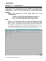
Windows Configuration .....................................................................................................................................................61
Installation ......................................................................................................................................................................61
Startup.............................................................................................................................................................................61
Print ................................................................................................................................................................................62
Configuration..................................................................................................................................................................62
I/O Configuration Menu .............................................................................................................................................62
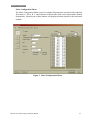
Meter Configuration ...................................................................................................................................................63
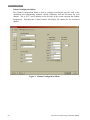
Channel Configuration Menu .....................................................................................................................................64
System Configuration Menu.......................................................................................................................................65
Print Menu ..................................................................................................................................................................66
BTU Menu......................................................................................................................................................................67
Downloading the Configuration .....................................................................................................................................67
Configuration Files .........................................................................................................................................................67
Downloading the Configuration .....................................................................................................................................68
Configuration Files .........................................................................................................................................................68
Saving Configuration Files .............................................................................................................................................68
Opening Configuration Files ..........................................................................................................................................68
Offline Editing............................................................................................................................................................... 68
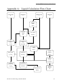
Appendix A: Liquid Calculation Flow Chart ...................................................................................................................69
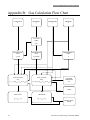
Appendix B: Gas Calculation Flow Chart ........................................................................................................................70
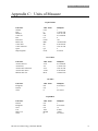
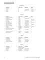
Appendix C: Units of Measure .........................................................................................................................................71
Appendix D: Error Messages ...........................................................................................................................................74
ii
HP-305 Nova-Flow Energy Calculator Manual
Specifications
Specifications
General Specifications
Environmental
Operating Temperature:
Storage Temperature:
Humidity:
-20C to 70C
-40C to 70C, with heater option.
(Only available with NEMA enclosure option)
-40C to 85C
0-95% Non-condensing
Approvals and Regulatory Compliance
CE
Standards:
AGA 8/API 14.2
AGA 7
OIML Tc 8 Sc 7, R117, R118
ISO 6551, 7637
NIST Handbook 44, 3.37
Enclosure
1/2 DIN panel mount, aluminum housing
Optional Ex proof, NEMA 4X
Power Supply
10 to 30 Volts DC, 2A max
85 to 265 VAC, 50/60Hz, 400mA max
Display
Keypad
128x64 graphical display displays 4 parameters simultaneously
Easy scroll through matrix of 48 parameters
LED back light
Adjustable contrast
3 soft keys
14 assigned keys
Embossed overlay
Stainless steel membrane switches
IR Interface (Optional)
Front panel infrared transmitter/receiver for remote operation and communication
Diagnostics
Multiple error messages
Failure detection for RTD and all analog inputs
System configuration and diagnostics from a PC computer through RS-232 port
Field Expandable Hardware and Software
Easy to add and replace modules
Software configuration based on installed modules
HP-305 Nova-Flow Energy Calculator Manual
1
Specifications
Diagnostics
Multiple error messages
Failure detection for RTD and all analog inputs
System configuration and diagnostics from a PC computer through RS-232 port
Field Expandable Hardware and Software
Easy to add and replace modules
Software configuration based on installed modules
Alarms
Multiple visual/audio alarms
HI/LO, HI/HI, LO/LO
Power and Energy
Supports Power and Energy calculations for heating and cooling applications
Separate registers available for Peak and Off-Peak times
Two Peak times may be configured within a 24-hour period
Optional dual flowmeter system is available for detecting fluid losses in heating and cooling systems
Flow Compensation and Calculation Methods
20-point flow linearization
FWD/REV tables for two channels
Mass and Volumetric calculations available for fluids
Up to 4 fluid properties tables
Security Features
Audit Trail with Time/Date/ID stamping for configuration changes
Hardware Specification
Nova Flow construction allows full flexibility in selecting flow computer functions. The base Nova-Flow unit provides
one flow meter input, and 8 digital I/O lines. Each I/O line can be configured as Input or Output. The unit has 8
expansion slots for optional I/O modules. Almost any combination of modules can be selected to meet the customer’s
individual needs.
BASE UNIT
Flow Meter Input
Selectable: Magnetic coil, MCP coil, TTL, Open Collector, Dry Contact
Frequency range: 0.2 to 5,000 Hz.
Amplitude: 10mVrms to 30Vrms
Digital I/O
7 digital lines selectable for Input or Output
One optically isolated Digital Output
Software configurable function: pulse output, remote clear, batch start/stop, batch control, alarms.
Selectable voltage level:0-5V, 0-10V, or Open Collector rated at 30Vdc, 250mA max.
Auxiliary 24 Vdc power supply @ max 100mA
2
HP-305 Nova-Flow Energy Calculator Manual
Specifications
OPTIONAL MODULES
Dual RTD and Dual Analog Input Module
Includes two RTDs and two analog inputs
Compatible with 100, 1000, and 2500 Ohm RTD probes
Analog inputs configurable for temperature, pressure, density, specific gravity, or flow
Accuracy 0.025%
Resolution 12 bit
Range 4-20mA, or 1-5V
Over voltage and over current protected
Analog Output Module
12 bit true D/A
Selectable 4-20mA, 1-5V
Current sourcing, or powered from external power supply
Dual Relay Module
Includes two SPDT relays
Dry Contact or Solid State Relays
Dry Contact: Vmax 125Vac, Imax 10A / Vmax 250 V ac, Imax 5A
Solid State: Vmax switching 175Vdc, Imax switching 250mA, Imax carry 1.5A
Software configurable for flow, temperature, pressure, and density alarms (high and low)
RS232 Port Module
Includes one RS232 serial port, screw terminal or DB9 connector
Printing, configuration, MODBUS interface
RS485 Port Module
Includes one RS485 serial port, screw terminal connector
Printing, configuration, MODBUS interface
Dual Pulse Out Module
Scaled pulse per unit of measure
Voltage level: 0-5V, 0-12V, Open Collector 30Vdc, 250mA max.
Flow B Module (second flow input)
Magnetic coil, MCP coil, TTL/CMOS, Open Collector, Dry Contact
Quadrature input for magnetic coil, ISO6551 level B compliant
Frequency range 0.2 to 5,000 Hz
Amplitude 10mVrms to 30Vrms
HP-305 Nova-Flow Energy Calculator Manual
3
Specifications
THIS PAGE LEFT INTENTIONALLY BLANK
4
HP-305 Nova-Flow Energy Calculator Manual
Architecture
Architecture
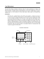
The Nova-Flow Energy Calculator architecture allows for many combinations of software and
hardware options. Its modular design can accommodate a variety of flow applications. The NovaFlow chassis has 8 expansion slots accessible through the rear panel to install optional “plug-in”
modules. There are several modules for various input signals, output signals, and communication
requirements.
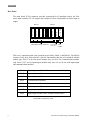
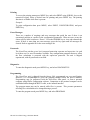
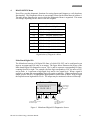
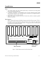
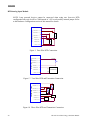
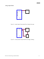
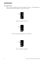
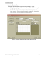
Front Panel
Nova-Flow has a graphical display with 64x128 pixel resolution. It displays five lines of
text: four lines are used for process parameters, and the fifth line at the bottom of the display
is used for software-controlled key labels. There are three software-controlled keys (softkeys) located under the display, two scroll keys on the right side of the display, and a
numerical keypad. Soft-key functions vary with the operating mode of the unit. The soft-key
labels are displayed above the soft-keys and change according to the operating mode. Two
scroll keys (UP and DOWN) are used to select display parameters, and to navigate through
the program menu. The numerical keypad is used to enter numerical values, or to select items
in the menu. Under the scroll keys there is an infrared window for communication with
computers equipped with IR interface.
Nova-Flow Front Panel
Display
Soft-key
labels
MENU
Scroll keys
12:00 SELECT
Soft-keys
HP-305 Nova-Flow Energy Calculator Manual
1
2
3
4
5
6
7
8
9
+/-
.
0
Infrared window
Numerical key pad
5
Architecture
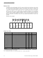
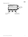
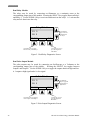
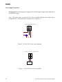
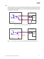
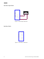
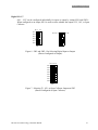
Rear Panel
The main board 18 Pin connector provides connection for all standard circuits: the flow
meter input, auxiliary 24 Vdc output, and 8 digital I/O lines configurable for either input or
output.
2
3 4
5
6
7 8
Slot 8 I/O COM
Slot 7 I/O
Slot 5 FLOW
Slot 4 COM
Slot 3 I/O
Slot 2 I/O
Slot 1 I/O COM
1
Slot 6 I/O
Block 2
Block 1
9 10 11 12 13 14 15 16 17 18
Main board 18 pin
- connector
Power Supply
Connector
Fuse
holder
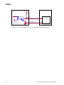
There are 8 optional module slots grouped in two blocks: Block 1 and Block 2. Each block
consists of four slots. Each slot has a specific functionality that has to be matched with the
module type. Slot #5 is for flow meter module only, slot #4 is for communication modules
only. Slots 2,3,6,7 are for input/output modules only, slots 1,8 are for use with input/output
and communication modules.
Slot 1
Input/output modules and Communication modules
Slot 2
Input/output modules
Slot 3
Input/output modules
Slot 4
Communication modules
Slot 5
Flow meter module
Slot 6
Input/output modules
Slot 7
Input/output modules
Slot 8
Input/output modules and Communication modules
Slot/Module Compatibility Table.
6
HP-305 Nova-Flow Energy Calculator Manual
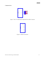
Architecture
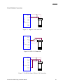
Optional Modules
There are three types of optional modules: input/output (I/O), communication (COM), and
flow meter modules. When installing a module, the type of module has to be matched with
the type of slot in the Nova-Flow chassis.
The following modules are available:
I/O Modules:
RTD/Analog Input
Analog output
Dual relay
Pulse out
Com Modules:
RS232
RS485
Flow Meter Module:
Flow B
A combination of the above modules results in over 50,000 different configurations available
for Nova-Flow.
Optional Modules
Module Name
RTD/ANALOG IN
ANALOG OUT
RELAY
PULSE OUT
RS232
RS232-DB9
RS485
FLOW B
Function
Dual RTD 2 or 3 wire, and dual analog input
4-20mA, or 1-5V
Analog output 4-20mA, or 1-5V
Dual SPST relay
Pulse output for frequency above 1Hz
Serial communication, terminal block
Serial communication, DB9 connector
Serial communication, terminal block
Flow meter input with pulse security
*See model number designation section
Available slot
Code #
1, 2, 3, 6, 7, 8
T1-T16*
1, 2, 3, 6, 7, 8
1, 2, 3, 6, 7, 8
1, 2, 3, 6, 7, 8
1, 4, 8
1, 4
1, 4, 8
5
A7, A8*
R1, R2*
P
S2
S9
S4
BM, BRF
Notes!
1. When a module is installed, removed, or moved to a different slot, the software
configuration has to be changed accordingly. Refer to section “Slot configuration”.
2. Hoffer recommends that Slot 1 is always equipped with a serial communication module
to allow configuration changes from a PC computer.
HP-305 Nova-Flow Energy Calculator Manual
7
Architecture
THIS PAGE LEFT INTENTIONALLY BLANK
8
HP-305 Nova-Flow Energy Calculator Manual
Model Number & Hardware Code
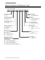
Model Number & Hardware Code
Nova Flow Model Number:
NFEN-A7-S2-MB-1-M-T1-1-H/L R1-P-F-BP-SP
Analog Outputs
(A7) 4-20mA
(A8) 1-5Vdc
Communication Ports
(S2)
(S4)
(S9)
RS232/ Screw Terminal
RS485/ Screw Terminal
RS-232-S9
Scaled Output Pulses
(MB) Mother board
(P)
Dual High Speed Output
Number of Channels
(1)
Single Channel
(B) Dual Channel, Bi- directional
(PSB) Pulse Security
(B3) 3 Channel Unit
(B4) 4 Channel
Flowmeter Input
(M)
(MC3PA)
(RPR)
(RPM)
(DMX)
(DRX)
Magnetic Coil
RF Coil
Redi-pulse RF coil
Redi-pulse Magnetic Coil
Redi-pulse I.S. Magnetic Coil
Redi-pulse I.S. RF Coil
Temperature/Pressure
Compensation, Analog
and RTD Inputs
(T1)
(T2)
(T3)
(T4)
(T5)
(T6)
(Z)
Special Features
(SP)
Any special features that are not
covered in the model number
Backplane
(B)
Second backplane, required if slots 6,
7, or 8 have been configured
(BPB) Use option if (B) dual channel has
been equipped in slot 5
Accessories/Options
(F)
(H)
Flowmeter mounted for (ND)
Heater for (ND) & E options only
Enclosure Style
(P)
(ND)
(E)
(C)
Panel Mount
Mounted on door with keypad
accessible
Explosion Proof, Visible thru window
Portable
Alarms
(H/L R1) ½ amp dual SPDT, high speed
200 Hz max
(H/L R2) Dual SPDT., 10 amp relays
Power Input
(1)
(2)
(*)
115 Vac 50/60 Hz
220 Vac 50/60 Hz
10-30Vdc
Two 4-20mA, two 100 ohm RTD inputs
Two 1-5Vdc, two 100 ohm RTD inputs
One 4-20mA, one 1-5Vdc, two 100 RTD inputs
Two 4-20mA, two 1000 ohm RTD inputs
Two 1-5Vdc, two 1000 ohm RTD inputs
One 4-20mA, one 1-5Vdc, two 1000 ohm RTD inputs
Add (Z) Compressability software after all options above for gas
HP-305 Nova-Flow Energy Calculator Manual
9
Model Number & Hardware Code
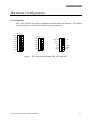
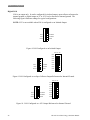
Hardware Code
In addition to the model number Nova Flow units are labeled with a hardware code to help
the factory identify installed hardware options. The hardware code consists of a string of up
to 8 symbols representing modules in the order they are installed in the chassis. Each symbol
stands for one module. An “X” indicates there is no module installed in the corresponding
slot. The first four symbols represent modules installed in the Block-1, the second four
symbols represent modules installed in the Block -2. The second four symbols are deleted if
there are no modules in the Block-2 slots. This also indicates that the Block-2 board is not
installed.
Hardware code example:
R1-T1-A7-S2-BM-D-X-X
Slot 1
Slot 2
Slot 3
Slot 4
Slot 5
Slot 6
Slot 7
Slot 8
Dual
Relay
RTD/
Analog
input
Analog
output
RS232
Flow B
Digital
I/O
None
None
Module Code Table
Module name
Flow B
Flow B
RS 232
RS 232-DB9
RS 485
RTD/Analog In - 1
RTD/Analog In - 2
RTD/Analog In - 3
RTD/Analog In - 4
RTD/Analog In - 5
RTD/Analog In - 6
Analog Output
Analog Output
Dual Relay -1
Dual Relay -2
Digital I/O
Pulse out
Description
Flow meter input, Mag or pulse coil
Flow meter input, RF coil
Serial communication, screw terminal.
Serial communication, DB9 connector.
Serial communication, screw terminal.
2x 100 RTD, 2x 4-20 mA
2x 100 RTD, 2x 1-5 V
2x 100 RTD, 1-5 V, 4-20mA
2x 1000 RTD, 2x 4-20 mA
2x 1000 RTD, 2x 1-5 V
2x 1000 RTD, 1-5 V, 4-20mA
4-20mA
1-5V
2x SPDT solid state
2x SPDT 10A, 250 VAC
7 TTL (5V) input/output lines
2x pulse output (<200Hz)
Type
Flow
Flow
Com
Com
Com
I/O
I/O
I/O
I/O
I/O
I/O
I/O
I/O
I/O
I/O
I/O
I/O
Code
BM
BRF
S2
S9
S4
T1
T2
T3
T4
T5
T6
A7
A8
R1
R2
D
P
Max #
1
1
3
1
3
*
*
*
*
*
*
2
2
3
3
2
1
*Total 2 RTD/Analog modules can be installed.
Com = communication module, I/O = input/output module, Flow = frequency input module
10
HP-305 Nova-Flow Energy Calculator Manual
Operation
Operation
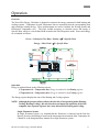
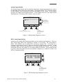
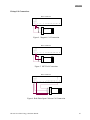
Overview
The Nova-Flow Energy Calculator is designed to measure the energy consumed in both heating and
cooling systems. Temperature In and Temperature Out are measured from the corresponding feed
and return line sensing devices. These measurements are used to calculate the flowing density and
Differential Temperature (T). The final variable necessary to calculate power and energy is
Specific Heat, which is a user defined field located in the Fluid Properties menu. Power and energy
are calculated as follows:
Power = Volumetric Flow Rate x Density x T x Specific Heat
Energy = Mass Total x T x Specific Heat
Temp
In
Temp
Out
Operation
Energy is totalized based on the following criteria:
If Temperature In > Temperature Out, Energy is totalized in the Heating register
If Temperature In < Temperature Out, Energy is totalized in the Cooling register
The Energy register displays the sum of the Heating and Cooling registers.
NOTE: Although the present software allows the selection of an operating mode (Heating,
Cooling, Heating/Cooling), this selection does not impact the operation of the flow
computer since separate registers have been allocated for Heating and Cooling.
Single Flowmeter System
In single flowmeter system, it is assumed that the flowmeter is connected on the feed line.
Density for mass calculations is based on the temperature measurement from Temperature In.
Channel A is the designated flow channel for a single flowmeter system.
HP-305 Nova-Flow Energy Calculator Manual
11
Operation
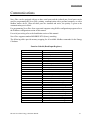
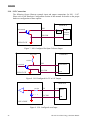
Dual Flowmeter System (Optional)
In a dual flowmeter system, the flowmeter on the feed line (Channel A) uses Temperature In
to calculate density, while the meter on the return line (Channel B) uses Temperature Out.
CH1/2 is the designated channel for displaying the results of math functions. For example,
CH1/2 may be configured to display any fluid losses between the feed and return lines
(Channel A – Channel B). This feature is useful for detecting leaks or other sources of fluid
loss in the system.
Peak and Off-Peak
The Nova-Flow Energy Calculator allows Peak and Off-Peak times to be designated, so that
energy totals are recorded into different registers, depending on the time of day. Two Peak
times may be configured within a 24-hour period. Peak and Off-Peak times are programmed
in the BTU Configuration menu.
The following section applies only to units that have already been programmed. For initial
programming and set up refer to the Menu Structure section of this manual.
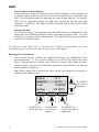
Displaying Process Parameters
The Nova-Flow energy calculator can simultaneously display any combination of four
process parameters. To set a desired parameter on one of the four display lines press
SELECT key until the line is selected, press CHAN key to choose a flow channel (on multichannel systems), and then scroll through the parameters using SCROLL keys until the
desired parameter is displayed.
Note: When a display line is selected, the center soft-key label changes from date/time to
CHAN on multi channel system.
Temp In
Temp Out
Power
Heating
MENU
Use MENU key to
enter the main menu
12
19 C
-12 C
15 kBTUh
272 kBTU
CHAN
Use SCROLL
keys to select
a parameter
SELECT
Use CHAN key
to select flow
channel
Use SELECT key
to select one of the 4
display lines
HP-305 Nova-Flow Energy Calculator Manual
Operation
The following process parameters are available for display:
Parameter
Uncorrected Total
Display
U/Total
Total
Total
Accumulated Total
Uncorrected Rate
AccTot
U/Rate
Rate
Rate
Temperature In
Temp In
Temperature Out
Temp Out
Differential
Temperature
Pressure
Diff. Temp
Pres
Power
Power
Peak Power
Heating
Accumulated Heating
Cooling
Accumulated Cooling
Energy
Accumulated Energy
Peak Energy
Accumulated Peak
Energy
Off-Peak Energy
Accumulated OffPeak Energy
Operating Time
Since Last Clear
Peak Power
Heating
Acc. Heating
Cooling
Acc. Cooling
Energy
Acc. Energy
Peak
Acc. Peak
Off-Peak
Acc Off-Peak
Oper. Time
Description
Volumetric total at flowing conditions, calculated based on turbine
calibration data (K-factor) stored in the Nova-Flow
Corrected total, compensated to a selected reference conditions,
expressed in units of volume or mass, depending on calculation and
compensation method.
Accumulated corrected total
Volumetric rate at flowing conditions, calculated based on turbine
calibration data (K-factor) stored in the Nova-Flow
Corrected rate, compensated to a selected reference conditions, expressed
in units of volume or mass, depending on calculation and compensation
method.
Actual flowing temperature measured on the feed line. It will display a
programmed default temperature whenever the default temperature is
being used for calculation, or “N/A” when temperature is not selected
for compensation.
Actual flowing temperature measured on the Return line. It will display a
programmed default temperature whenever the default temperature is
being used for calculation, or “N/A” when temperature is not selected
for compensation.
The result of Temp In – Temp Out, used to calculate energy.
Actual flowing pressure. It will display a programmed default pressure
whenever the default pressure is being used for calculation, or “N/A”
when pressure is not selected for compensation.
The calculated rate of energy consumption based on mass flow rate,
differential temperature and the specific heat of the fluid.
Displays the highest rate of power that has occurred during operation
Energy total based on Temp In > Temp Out
Accumulated Heating total
Energy total based on Temp In < Temp Out
Accumulated Cooling total
The sum of Heating Energy and Cooling Energy
The sum of Acc. Heating and Acc. Cooling
Energy totalized (Heating +Cooling) during programmed peak time.
Accumulated energy (Acc Heating + Acc Cooling) totalized during
programmed peak time.
Energy totalized (Heating + Cooling) during off-peak time.
Accumulated energy (Acc Heating + Acc Cooling) totalized during
programmed off-peak time.
Displays the time in HH:MM:SS since the last clearing of totals
occurred.
On multi-channel system parameters are displayed with extensions Ch A, Ch B, Ch C, or Ch
D to identify the flow channel they are associated with. Energy calculations are executed
using channels A and B, however, Channels C and D may be used to monitor flowrates using
an analog input.
HP-305 Nova-Flow Energy Calculator Manual
13
Operation
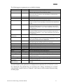
Displaying Date and Time
Time or date is displayed in the center soft-key field, when this field is not being used.
MENU
12:00
SELECT
When time or date is displayed use the center soft-key to switch between the time and date.
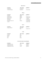
Displaying Base Conditions
Currently configured Base Operating Conditions may be displayed by pressing the +/- key on
the numerical keypad.
Base Conditions
Temp= 21.00C
Pres= 101.32k Pas-a
OK
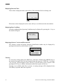
Displaying Software Version and Electronic ID
The software version and unique electronic identification number may be displayed by
pressing the decimal key on the numeric keypad.
H Hoffer Flow Controls
NOVA FLOW
Version 1.00.3052
Unit ID 121108987
Clearing
To access the clearing menu press MENU key, and select CLEAR using ARROW keys or
the numerical keypad. Select an item from the menu and press the CLEAR key. A message
“Are you sure” will be displayed. Press YES key if you still want to clear a register. After
pressing the YES key to confirm, information stored in the register will be lost.
Clearing is not available while flow is present. A warning message will be displayed when
CLEAR key is pressed while flow is present.
14
HP-305 Nova-Flow Energy Calculator Manual
Operation
Printing
To access the printing menu press MENU key, and select PRINT using SCROLL keys or the
numerical keypad. Select a desired item for printing and press PRINT key. The printing
function is available while flow is present.
Example:
To print configuration data press MENU, select PRINT, CONFIGURATION, and press
PRINT key.
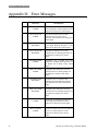
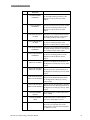
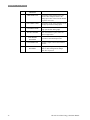
Error Messages
There are a number of warnings and error messages that guide the user if there is an
operational problem or conflict in the configuration parameters. When an error occurs the
center soft-key label switches to “Errors”. Press the ERRORS key to view and acknowledge
errors. If there is more than one error message, press the key again until all messages are
cleared. Refer to appendix D for the error messages list.
Passwords
The Nova-Flow unit has a two level password protection: operator and supervisor. At each
level there are five user ID numbers available. Any configuration parameter that may affect
the flow calculation is protected with the supervisor password. The unit is shipped
unprotected, with all passwords set at 0000.
Diagnostics
To enter the diagnostic mode press MENU key, and select DIAGNOSTICS.
Programming
The Nova-Flow unit is shipped from the factory fully programmed per user specification.
However, it is recommended to verify the program settings before the unit is installed.
Programming may be performed from the Nova-Flow front panel, or from a personal
computer using Hoffer configuration software. Connection to the personal computer can be
established either through the RS232 cable, or the infrared interface.
The program menu may not be entered while flow is present. This prevents parameters
affecting flow calculations to be changed during a process.
To enter the program mode press MENU key, and select PROGRAM.
HP-305 Nova-Flow Energy Calculator Manual
15
Operation
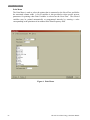
Selecting a Menu Item
The Nova-Flow program menu is a multi-layer matrix of submenus. Refer to the menu chart
in the Menu Structure section for help navigating through the menu structure and locating a
desired menu item.
Main Menu
1. Clear
2. Print
3. Program
4. Diagnostics
SELECT
Use SELECT key to
enter selected item
HOME
Use SCROLL
keys to move
selection bar
EXIT
Use HOME key to
return to operate
screen
Use EXIT key to move
one level up
Reviewing Settings
Program settings are displayed at the lowest level in the program menu. Once a menu item is
selected, it can be changed using the EDIT key.
Utility functions
Keypad enable
Yes
Keypad timeout
10 sec
EDIT
Use EDIT key to
edit mode
16
HOME
Use HOME key to
return to main
Use SCROLL
keys to move
selection bar
EXIT
Use EXIT key to
one level up
HP-305 Nova-Flow Energy Calculator Manual
Operation
Editing Program Settings
Utility functions
Keypad timeout
10
sec
ACCEPT
Use ACCEPT key to accept
the selection and exit to
review mode
HP-305 Nova-Flow Energy Calculator Manual
Use SCROLL
keys or numerical
keys to change
the value
ERASE
Use ERASE/CANCEL key
to return to review mode
without changing selection
17
Operation
THIS PAGE LEFT INTENTIONALLY BLANK
18
HP-305 Nova-Flow Energy Calculator Manual
Menu Structure
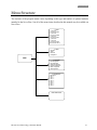
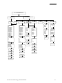
Menu Structure
The structure of the program menus varies depending on the type and number of optional modules
installed in the Nova-Flow. Not all of the menu items described in this manual may be available on
Nova-Flow.
1. CLEAR
1. Total CH A
2. Accum total CH A
3. Total CH B
4. Accum total CH B
5. Total CH C
6. Accum total CH C
7. Total CH D
8. Total CH ½
9. Accum total CH D
10. Accum total CH 1/2
2. PRINT
1. Variables
2. Ticket
3. Audit Trail
4. Configuration
MENU
3. PROGRAM
1. BTU Configuration
2. I/O Configuration
3. System Configuration
4. Channel Configuration
5. Meter Configuration
6. Slot Assignments
4. DIAGNOSTICS
1. Main board
2. Slot 1 - ...
3. Slot 2 - ...
4. Slot 3 - ...
5. Slot 4 - ...
6. Slot 5 - ...
7. Slot 6 - ...
8. Slot 7 - ...
9. Slot 8 - ...
BASE CONDITIONS
HP-305 Nova-Flow Energy Calculator Manual
19
Menu Structure
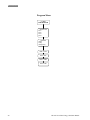
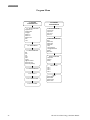
Program Menu
3.1. BTU
CONFIGURATION
SELECT FLUID
Fluid 1
Fluid 2
Fluid 3
Fluid 4
BTU MODE
Heating
Cooling
Heating/Cooling
PEAK1 - START
PEAK1 - END
PEAK 2 - START
PEAK 2 - END
20
HP-305 Nova-Flow Energy Calculator Manual
Menu Structure
3.2. I/O CONFIGURATION
3.2.1. MAIN BOARD
I/O
DIGITAL I/O
1-8
FUNCTION
Off
Remote Clear
Flow/U Alarm
Flow/V Alarm
Flow/M Alarm
Temp Alarm
Press Alarm
Delta T Alarm
Power Alarm
Pulse/U out
Pulse/V out
Pulse/M out
Pulse/E out
CHANNEL
A
B
C
D
CH1/2
3.2.2. MODULE I/O SLOT 1-8
DIGITAL I/O
1-7
QUAD RTD/
ANALOG IN
DUAL RELAY
Off
Flow/U Alarm
Flow/V Alarm
Flow/M Alarm
Temp Alarm
Press Alarm
Delta T Alarm
Power Alarm
Pulse/U out
Pulse/V out
Pulse/M out
Pulse/E out
Limit
Deadband
Logic
Pulse scale
FLOW B
RS232/485
MODE
Off
Modbus
Printer
FUNCTION
RTD 1,2
Off
100
1000
2500
DIN 100
CHANNEL
Temp In
Temp Out
CHANNEL
A
B
C
D
CH1/2
TYPE
High alarm
Low alarm
High warning
Low warning
ANALOG OUT
CHANNEL
Calibration
P
TYPE
High alarm
Low alarm
High warning
Low warning
Limit
Deadband
FUNCTION
Off
Pressure
Temperature
Delta T
Flow/U
Flow/V
Flow/M
Power
Calibration
Q
A
B
C
D
CH 1/2
Min value
BAUD
1200
2400
4800
9600
19200
Modbus
address
HIGH SPEED OUT
High Speed
out 1, 2
FUNCTION
On/Of
Pulse/U out
Pulse/V out
Pulse/M outf
Pulse/E out
CHANNEL
A
B
C
D
CH1/2
Pulse scale
Max value
Calibration P
Calibration Q
Pulse scale
Sound
Sound
HP-305 Nova-Flow Energy Calculator Manual
21
Menu Structure
Program Menu
3.3. SYSTEM
CONFIGURATION
3.3.1. UTILITY FUNCTIONS
Keypad time out
Keypad enable
Language
Define Ch 1
Define Ch 2
Define function
Date
Time
3.3.2. PASSWORD/PIN
3.3.4. BASE CONDITIONS
Nist
Oiml
Ptb
Sirim
Asian
Custom
Z@base conditions
Ref. density units
Ref. density (water/air)
3.4. CHANNEL
CONFIGURATION
CALCULATION METHOD
Liquid volume
Liquid mass
Gas volume
Gas mass
COMPENSATION METHOD
None
Default temp
Default press
Defalul T&P
Temp
Temp & Pressure
Temp @ Default Press
Density
Mimic Ch A
DEFAULT CONDITION
Temperature
Pressure
Density
SELECT FLUID
3.3.3. FLUID PROPERTIES
Fluid 1
Fluid 2
Fluid 3
Fluid 4
3.3.3.X. FLUID 1-4
3.3.3.X.1. DENSITY TABLE
UNITS
English default
Metric default
English custom
Metric custom
3.2.3.X.2. UVC TABLE
22
HP-305 Nova-Flow Energy Calculator Manual
Menu Structure
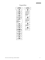
Program Menu
3.5. METER
CONFIGURATION
3.6. SLOT
CONFIGURATION
ON/OFF
Serial Number
Filtering
Correction Factor
SLOT #1,8
RTD/Analog module
Dual Relay module
Analog Out module
RS 232 module
RS 485 module
HS Pulse out
Min Flow Meter Frequency
LINEARIZATION
Average K-factor
K-factor table
Average meter factor
Metre factor table
UVC table
K-Factor Units
Average K Factor
K-Factor Table Fwd
SLOT #2,3,6,7
RTD/Analog module
Dual Relay module
Analog Out module
HS Pulse out
SLOT #4
RS 232 module
RS 485 module
SLOT #5
Flow B module
K-Factor Table Rev
Meter Factor Units
Meter Factor Table Fwd
Meter Factor Rev
UVC Table Fwd
UVC Table Rev
HP-305 Nova-Flow Energy Calculator Manual
23
Menu Structure
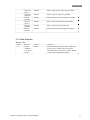
1. CLEAR Menu
1.
2.
3.
4.
5.
6.
7.
Total CH A
Total CH B
Accum Total CH A
Accum Total CH B
Total CH C
Total CH D
Accum Total CH 1/2
Select an item from the above menu and press the CLEAR key. A message “Are you sure”
will be displayed. Press “YES” key if you still want to clear a register. After pressing the
“YES” key to confirm, information stored in the register will be lost.
2. PRINT Menu
1. Variables
2. Ticket
3. Audit Trail
4. Configuration Data
Select a desired item from the above menu and press the PRINT key.
Variables for printing may be selected from the following list located in the Windows
Configuration program:
Uncorrected Total
Uncorrected Accumulated Total
Total
Accumulated Total
Uncorrected Rate
Rate
Temperature
Pressure
Density
On multi-channel system variables are printed with extensions Ch A, Ch B, Ch C, or Ch D
to identify the flow channel they are associated with. Energy calculations are executed
using Channels A and B, however, Channels C and D may be used to monitor flowrates
using an analog input.
Variables may be printed automatically at user-defined time intervals. This function is
configured by entering an interval in minutes in the Print Frequency field located in the
Windows Configuration Print Menu.
NOTE:
Selecting variables and setting the print time interval are available only from the Windows
Configuration program.
24
HP-305 Nova-Flow Energy Calculator Manual
Menu Structure
3. PROGRAM Menu
1.
2.
3.
4.
5.
6.
BTU configuration
I/O Configuration
System Configuration
Channel Configuration
Meter Configuration
Slot Assignment
This section describes the program menu fields in detail. Whenever applicable the
description is presented in the following format:
Address
Menu item
Selection
Comments
The paragraph numbers is this chapter correspond with the menu address. The address can
be used as a shortcut to a menu item. A menu can be accessed quickly from the Nova-Flow
front panel by pressing the MENU key and the address number on the numerical keypad.
An alternative method of accessing a menu item is using SCROLL and SELECT keys as
described in the Operation section.
The lowest level submenu items have no numerical address assigned, and selections are
made using the SCROLL keys.
Example:
Address
Menu
Selection
Comments
3.3.1
Date/Time
Enter date and
time
This menu allows to set time and date.
To access the Date/Time field using numerical address:
press MENU key,
press “3” key,
press “3” key,
press “1” key,
scroll the selection bar down to Date/Time field.
NOTE: The Slot Assignments must be programmed before any other configuration can
be performed, if the unit is being setup for the first time, or if there have been
changes to the installed optional modules.
HP-305 Nova-Flow Energy Calculator Manual
25
Menu Structure
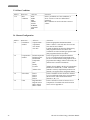
3.1. BTU Configuration
Address
3.1
Menu item
Select Fluid
3.1
BTU Mode
3.1
3.1
3.1
3.1
Peak1 Start
Peak1 End
Peak2 Start
Peak2 End
Selection
Fluid 1
Fluid 2
Fluid 3
Fluid 4
Heating
Cooling
Heating/Cooling
Enter time
Enter time
Enter time
Enter time
Comments
Select the fluid table to be used for processing.
Select mode of operation
NOTE: Although the present software allows
the selection of an operating mode (Heating,
Cooling, Heating/Cooling), this selection does
not impact the operation of the flow computer
since separate registers have been allocated for
Heating and Cooling.
Enter start time for Peak period 1.
Enter end time for Peak period 1.
Enter start time for Peak period 2.
Enter end time for Peak period 2.
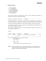
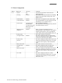
3.2. I/O Configuration
3.2.1. Main Board I/O
3.2.1…8
Digital I/O 1-7
I/O1 through I/O7 can be configured for input or output by selecting a dip switch
combination on the main board. Outputs are configurable for 5V, 10Vdc, or open
collector. I/O 8 is an output only and can be configured as an opto-isolated output. Refer
to the Hardware configuration section for details.
Address
3.2.1
Menu item
Function
Selection
Remote clear
Flow alarm
Temperature alarm
Pressure alarm
Delta T alarm
Power alarm
Pulse out (Flow,
Energy)
Comments
Select a function for digital I/O line.
Remote clear not available for I/O8.
3.2.1
Channel
Channel A
Channel B
Channel C
Channel D
Ch1/2
Select applicable flow channel for digital I/O.
This menu applies to multi-channel systems only.
High alarm
Low alarm
High warning
Low warning
Select a desired alarm type. This menu applies to
alarm output only.
Warnings display message on the front panel, and
sounds the buzzer if sound is selected. Alarms
display message, sounds buzzer, and logs error
message into the error log.
3.2.1
26
Type
Ch1/2 is defined in System Configuration (3.2.1)
HP-305 Nova-Flow Energy Calculator Manual
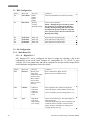
Menu Structure
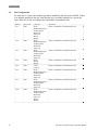
3.2.1
Limit
Number
3.2.1
Deadband
Number
3.2.1
Logic
Active low
Active high
3.2.1
Pulse scale
1, 10, 100, 1000
3.2.1
Sound
On
Off
Enter an alarm set point within the operating
range of the parameter (Min-Max).
Enter a value in the currently selected units alarm
to avoid spurious switching around the alarm set
point. Recommended value is about 1-5% of the
range.
For active low the output changes from high level
to low level when alarm condition occurs.
For active high the output changes from low level
to high level when alarm condition occurs.
Select a scaling factor. This menu applies to pulse
output only. “1” means one pulse is output for
each unit of volume.
Activates front panel buzzer when alarm
condition occurs.
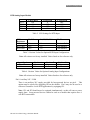
In the actual configuration the word “module” in the menu item is replaced with the name of the
module installed in this slot, according to the Slot Assignment settings, chapter 3.5.
Example:
Slot 1- RS232
Slot 2- RTD/Analog
Slot 3- Relay
Slot 4- RS232
Slot 5- None
Slot 6- None
Slot 7- None
Slot 8- None
The above examples represent a configuration consisting of four modules installed in slots 1-4.
To configure a module, select a desired slot in which the module is installed, and follow the
corresponding module menu.
HP-305 Nova-Flow Energy Calculator Manual
27
Menu Structure
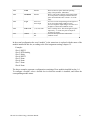
3.2.2. Module I/O Slots 1-8
Address
3.2.2.1-8.
Menu item
Slot 1-…8
module*
Selection
Varies with slots.
Refer to table
below
Comments
Select a slot to configure module installed in this
slot.
In the actual configuration the word “module” in the menu item is replaced with the name
of the module installed in this slot, according to the Slot Assignment settings, chapter 3.5.
Example:
Slot 1- RS232
Slot 2- RTD/Analog
Slot 3- Relay
Slot 4- RS232
Slot 5- None
Slot 6- None
Slot 7- None
Slot 8- None
The above examples represents a configuration consisting of four modules installed in
slots 1-4. To configure a module, select a desired slot in which the module is installed,
and follow the corresponding module menu.
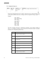
Slot
1
28
Compatible modules
RTD/Analog Input, Analog output, Dual relay, Hi
speed pulse out. RS232, RS485.
2
RTD/Analog Input, Analog output, Dual relay, Hi
speed pulse out.
3
RTD/Analog Input, Analog output, Dual relay, Hi
speed pulse out.
4
RS232, RS485.
5
Flow B.
6
RTD/Analog Input, Analog output, Dual relay, Hi
speed pulse out.
7
RTD/Analog Input, Analog output, Dual relay, Hi
speed pulse out.
8
RTD/Analog Input, Analog output, Dual relay, Hi
speed pulse out. RS232, RS485.
HP-305 Nova-Flow Energy Calculator Manual
Menu Structure
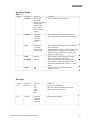
Dual Relay Module
Relay 1, 2
Address
Menu item
Function
Selection
Remote clear
Flow alarm
Temperature alarm
Pressure alarm
Delta T alarm
Power alarm
Pulse out (Flow,
Energy)
Comments
Select a function for a relay output.
Channel
Channel A
Channel B
Channel C
Channel D
Ch1/2
Select applicable flow channel for digital I/O.
This menu applies to multi-channel systems only.
Type
High alarm
Low alarm
High warning
Low warning
Limit
Number
Deadband
Number
Sound
On
Off
Select a desired alarm type. This menu applies to
alarm output only.
Warnings display message on the front panel, and
sounds the buzzer if sound is selected. Alarms
display message, sounds buzzer, and logs error
message into the error log.
Enter an alarm set point within the operating
range of the parameter (Min-Max).
Enter a value in the currently selected units to
avoid spurious switching around the alarm set
point. Recommended value is about 1-5% of the
range.
Activates front panel buzzer when alarm
condition occurs.
Address
N/A
Menu item
RTD 1, 2
Selection
Off
100
1000
2500
DIN
Comments
Select a type of RTD probe.
100, 1000, 2500 are platinum 3902 material
DIN is platinum 0385 material
N/A
Channel
Channel A
Channel B
Channel C
Channel D
Select applicable channel.
RTD Input
HP-305 Nova-Flow Energy Calculator Manual
29
Menu Structure
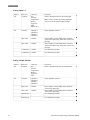
Analog Input 1, 2
Address
N/A
N/A
Menu item
Function
Selection
Off
Pressure
Temperature
Density
Sp gravity
Flow
Mimic Ch A
Comments
Select a desired function for the analog input.
Channel
Channel A
Channel B
Channel C
Channel D
Select applicable channel.
Min value
Number
Max value
Number
Calibration P
Number
Enter a number corresponding to the minimum
value for the input range, in the units selected for
the input.
Enter a number corresponding to the maximum
value for the input range, in the units selected for
the input..
See calibration procedure
Calibration Q
Number
See calibration procedure
Selection
Off
Pressure
Temperature
Density
Sp gravity
Flow
Comments
Select a desired function for the analog output.
Channel
Channel A
Channel B
Channel C
Channel D
Select applicable channel.
Min value
Number
Max value
Number
Calibration P
Enter a number corresponding to the minimum
value for the input range.
Enter a number corresponding to the maximum
value for the input range.
See calibration procedure.
Calibration Q
See calibration procedure.
Mimic Ch A is used to copy analog input data
from Ch A for the selected input function.
Analog Output Module
Address
N/A
N/A
30
Menu item
Function
HP-305 Nova-Flow Energy Calculator Manual
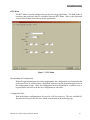
Menu Structure
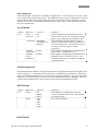
Split Analog Out
A split analog output is available for Forward/Reverse applications. 4 mA is maximum reverse flow, 12 mA is
0 flow, and 20 mA is maximum forward flow. The FWD/REV function in the I/O Configuration for Flow B
must be enabled. When entering Min and Max parameters for the Analog Output Configuration, enter the
maximum reverse flow rate in the Min field preceded with a negative sign(-). Enter the maximum forward
flow rate in the Max field.
Flow B Module
Address
N/A
Menu item
Error
Detection
Alt Function
Selection
On
Off
Independent
Forward/Reverse
Manifold
Manifold
Number
Switch Level
Manifold
Number
Switch
Deadband
Comments
Activates transmission error detection circuit on
dual coil meter systems. The circuit detects missing
pulses or pulses induced on the transmission lines.
Select Independent for independent operation of
Channel A and Channel B. Select Forward/Reverse
for bi-directional meters. Forward and reverse flow
are being counted into registers A and B,
respectively.
Enter a number corresponding to a manifold switch
point in units of volumetric flow rate.
Enter a number corresponding to a manifold switch
deadband in units of volumetric flow rates. The
switch point value has to be within the overlapping
range of the meters.
Manifold Application
In manifold application Channel A is assigned to the high flow range meter and Channel B is assigned to the
low flow range meter. A combined total from both meters is calculated using A+B function. The manifold
relay is activated and the manifold valve is closed when Nova Flow is powered up. The relay is deactivated
and the valve is opened when flow rises above the value of Manifold Switch Point + Deadband. The relay is
activated and the manifold valve is closed when flow drops below the Manifold Switch Point.
RS232 Module
Address
N/A
Menu item
Mode
Baud
Selection
Off
Modbus
Printer
1200
2400
4800
9600
19200
Comments
Select Modbus for communication with a PC
computer or Modbus master device. Select Printer
for printing function.
Select a desired baud rate.
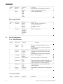
RS485 Module
HP-305 Nova-Flow Energy Calculator Manual
31
Menu Structure
Address
N/A
Menu item
Mode
Selection
Off
Modbus
1200
2400
4800
9600
19200
Comments
Select Modbus for communication with a PC
computer or Modbus master device.
Select a desired baud rate.
Menu item
Function
Selection
On/Off
Pulse/U
Pulse/V
Pulse/M
Comments
Select a function for the pulse out:
U- uncorrected volume
V- corrected volume
M- mass
Channel
Channel A
Channel B
Channel C
Channel D
CH1/2
Select a flow channel
Baud
Pulse Output Module
Address
N/A
3.3.
System Configuration
3.3.1. Utility Functions
Address
Menu item
Selection
Keypad
enable
Yes
No
Keypad
time out
Enter a number of
seconds
Range: 0-
Language
English
Spanish
Enter date and
time
Ch A
Ch B
Date/Time
Define Ch1
Define Ch2
Define
function
Ch B
Ch C
Ch D
Ch1-Ch2
Ch1+Ch2
Comments
If “No” is selected the front panel keys are
disabled.
To enable, press any key and enter a password
when prompted.
If the unit is left in the program mode, it will
switch back to the operate mode when limit is
reached.
Zero means the time out function is disabled.
Select a desired language.
This menu is used to set time and date.
This function allows to calculate combined (+ or ) total from two flow channels. Assign channel A
or B for operant Ch1 for math calculations.
Assign channel B, C, or D for operant Ch2 for
math calculations.
Select addition or subtraction for calculating a net
total.
3.3.2. Password/Pin
Address
32
Menu item
Selection
Comments
HP-305 Nova-Flow Energy Calculator Manual
Menu Structure
Supervisor
pin #1-5
Supervisor
password
Reenter
password
Operator
pin #1-5
Operator
password
Reenter
password
Number
Enter a 4 digit for each supervisor pin number.
Number
Enter a 4 digit for supervisor password.
Number
Enter the supervisor password again to confirm.
Number
Enter a 4 digit for each operator pin number.
Number
Enter a 4 digit for operator password.
Number
Enter the operator password again to confirm.
Selection
Number
Comments
Enter default temperature, pressure, density and
specific gravity. Default values are used for
calculation when a sensor fails, or when “default”
is selected for compensation method.
3.3.3. Fluid Properties
Density Table
Address
3.3.3
Menu item
Default
conditions
T, P, D, Sp
Gravity
HP-305 Nova-Flow Energy Calculator Manual
33
Menu Structure
3.3.4. Base Conditions
Address
3.3.4.
Menu item
Base
conditions
Selection
NIST
OIML
PTB
SIRIM
ASIAN
NORMAL
CUSTOM
NBP
Comments
Select a predefined set of base conditions, or
select “custom” to enter user defined base
conditions.
Base conditions are used to calculate corrected
volume.
3.4. Channel Configuration
Address
3.4.
3.4.
Menu item
Calculation
method
Compensation
method
Selection
Liquid volume
Liquid mass
Gas volume
Gas mass
Default temperature
Default pressure
Default T&P
Temperature
T&P
Density
T,P, &D
*Mimic CHA
34
3.4.
Select fluid
3.4.
Units
Fluid 1
Fluid 2
Fluid 3
Fluid 4
English default
English custom
Metric default
Metric custom
Comments
Select an appropriate calculation method.
When “volume” is selected, mass flow rate and
mass total are not available.
Liquids calculations are based on fluid property
table programmed in the Nova Flow. Gas
calculations are based on ideal gas equation and Z
table programmed in the Nova Flow.
Select an appropriate compensation method.
For T, P, D compensation an associated sensor
has to be connected and an analog input has to be
programmed accordingly. When a sensor fails, the
default value is used for calculations.
*Mimic CHA is added to the list of Compensation
Methods for Channels B, C, and D. When this
method is selected, compensation parameters for
channel A are applied to the designated channel.
Select a fluid table for the current flow channel.
Up to four different fluids can be programmed in
the Nova Flow and switched between flow
channels A, B, C, D.
Select a desired set of units of measure. For a
complete list of available units and conversion
factors refer to appendix xx.
HP-305 Nova-Flow Energy Calculator Manual
Menu Structure
3. 5. Meter Configuration
Address
3.5.1.
Menu item
On/off
Filtering
Selection
On
Off
Number
Serial number
Correction factor
Number
Number
Linearization
Average K-factor
K-factor table
Average meter factor
Meter factor table
UVC table
Number
Minimum meter
frequency
K-factor units
Average K-factor
Number
K-factor table
forward
Meter factor units
Average meter
factor
Meter factor table
Number
UVC table
HP-305 Nova-Flow Energy Calculator Manual
Comments
“On” has to be selected to activate the flow
channel operation.
This number represents the amount of smoothing
applied to the input signal coming from a meter.
Default value is…
Enter up to a 10- digit flow meter serial number
User selected number to correct the flow rate and
total. Range: 0.5-1.5. Default value is 1.
Select an applicable method.
The menus below will be displayed only when the
associated method is selected.
Enter a frequency in Hz that is below an
operating range of input frequency. Any signal at
frequency below the min. value is considered a
“noise” and it will be rejected. Default value is 0.
Select units of measure for K-factor
This menu is displayed when Average K-factor
selected for linearization method. Enter a K-factor
for the meter connected to this channel.
This menu is displayed when K-factor table fwd is
selected for linearization method. For every point
of the table enter frequency in Hz and K-factor
value.
Select units of measure for meter factor
This menu is displayed when Average meter
factor is selected for linearization method.
This menu is displayed when Meter factor table is
selected for linearization method. For every point
of the table enter frequency in Hz and K-factor
value.
This menu is displayed when UVC table is
selected for linearization method. For every point
of the table enter frequency/viscosity in Hz/ctsk
and K-factor value.
35
Menu Structure
3.6.
Slot Configuration
For each slot (1-8) select the module type that is installed in this slot. Select NONE, if there
is no module installed in the slot. Note that the list of available modules for a given slot
varies from slot to slot, according to the slot/module compatibility table.
36
Address
3.6.1.
Menu item
Slot 1
3.6.2.
Slot 2
3.6.3.
Slot 3
3.6.4.
Slot 4
3.6.5.
Slot 5
3.6.6.
Slot 6
3.6.7.
Slot 7
3.6.8.
Slot 8
Selection
None
RTD/Analog Input
Analog output
Dual relay
Pulse out
RS232
RS485
None
RTD/Analog Input
Analog output
Dual relay
Pulse out
None
RTD/Analog Input
Analog output
Dual relay
Pulse out
None
RS232
RS485
None
Flow B
None
RTD/Analog Input
Analog output
Dual relay
Pulse out
None
RTD/Analog Input
Analog output
Dual relay
Pulse out
None
RTD/Analog Input
Analog output
Dual relay
Pulse out
RS232
RS485
Comments
Select a module that is installed in this slot.
Select a module that is installed in this slot.
Select a module that is installed in this slot.
Select a module that is installed in this slot.
Select a module that is installed in this slot.
Select a module that is installed in this slot.
Select a module that is installed in this slot.
Select a module that is installed in this slot.
HP-305 Nova-Flow Energy Calculator Manual
Menu Structure
4.
DIAGNOSTICS Menu
Nova-Flow provides diagnostic functions for testing Inputs and Outputs to verify hardware
functionality. The Diagnostics Menu is conveniently located in the Main Menu at address 4.
The table below illustrates the way in which the Diagnostics Menu is organized. This menu
will change depending on how the I/O slots are assigned.
Address
Menu Option
4.1
Main board DigIO
4.2
Slot1 – Assigned Module Name
4.3
Slot2 – Assigned Module Name
4.4
Slot3 – Assigned Module Name
4.5
Slot4 – Assigned Module Name
4.6
Slot5 – Assigned Module Name
4.7
Slot6 – Assigned Module Name
4.8
Slot7 – Assigned Module Name
4.9
Slot8 – Assigned Module Name
Organization of Diagnostics Menu
Main Board Digital I/O
The Main board consists of 8 Digital I/O lines, of which I/O1-I/O7 can be configured as an
input or an output and I/O8 only as an output. The figure below illustrates the layout of the
Main board Digital I/O diagnostics screen. The 1s and 0s represent corresponding I/O lines,
counting from left to right. For example, the first digit corresponds to I/O1, the next to I/O2,
and so forth. A 1 represents a high signal level and 0 a low signal level. When a signal is
applied to an input, the corresponding digit will toggle accordingly. When configured as an
output, presses SELECT to highlight the appropriate I/O and use the SCROLL keys to toggle
the output between high and low levels. The output may be monitored with an oscilloscope.
Mainboard DIO
Use SCROLL
keys to toggle
the outputs
I: 0 0 0 0 0 0 0 1
O: 1 0 0 0 1 0 0 1
SELECT
Use SELECT key to select
the desired output
EXIT
Use EXIT key to move
up to the Diagnostics
Main Menu
Figure 1. Main board Digital I/O Diagnostics Screen
HP-305 Nova-Flow Energy Calculator Manual
37
Menu Structure
Dual Relay Module
The relays may be tested by connecting an Ohmmeter or a continuity tester to the
corresponding output pins of the module. Pressing the SELECT key toggles between Relay1
and Relay 2. Use the SCROLL Keys to activate and deactivate the relays. A 1 activates the
relay and a 0 deactivates the relay.
Relay Slot: #
Use SCROLL
keys to activate
and deactivate
the relays.
O1: 0
O2: 0
SELECT
EXIT
Use EXIT key to move
up to the Diagnostics
Main Menu
Use SELECT key to toggle
between Relay 1 and Relay 2.
Figure 2. Dual Relay Diagnostics Screen
Dual Pulse Output Module
The pulse outputs may be tested by connecting an Oscilloscope or a Voltmeter to the
corresponding output pins of the module. Pressing the SELECT key toggles between
Output1 and Output2. Use the SCROLL Keys to toggle the outputs between high and low.
A 1 outputs a high signal and a 0 a low signal.
HsOut Slot: #
Use SCROLL
keys to toggle the
outputs between
high and low.
O1: 0
O2: 0
SELECT
Use SELECT key to toggle between Output 1 and Output 2.
EXIT
Use EXIT key to move
up to the Diagnostics
Main Menu
Figure 3. Pulse Output Diagnostics Screen.
38
HP-305 Nova-Flow Energy Calculator Manual
Menu Structure
Analog Output Module
The Analog Output Module may be tested by connecting a current measuring device, such as
an amp meter, to the output pins of the module. Pressing the SELECT key selects the output.
Use the SCROLL keys to increase or decrease the number of D/A counts. As the number
increases, the output current should increase. As the number decreases, the output current
should decrease. The range of D/A counts is from 0 to 4095.
AO Slot: #
Use SCROLL
keys to increase or
decrease the number of D/A counts.
AO: 0
SELECT
EXIT
Use SELECT to highlight the output.
Use EXIT key to move
up to the Diagnostics
Main Menu
Figure 4. Analog Output Diagnostics Screen.
RTD/ Analog Input Module
Operation of an installed RTD/Analog module may be verified using diagnostics. There are
four Analog Input labels each displaying a number of A/D counts. AI1 corresponds to
RTD1, AI2 to RTD2, AI3 to Analog CH1, and AI4 to Analog CH2. A/D counts for a
configured input should always be between 0 and 4095 during normal operation. As the
transmitter signal increases, the number of A/D counts should also increase. As the RTD
temperature increases, the number of A/D counts should also increase. If the counts become
0 or 4095, either the module has not been installed, configured, or calibrated, or there is an
RTD or Transmitter failure.
AI Slot: #
RTD1:1255 RTD2:4095
AI1:2354
AI2:4095
EXIT
Use EXIT key to move
up to the Diagnostics
Main Menu
Figure 5. RTD/Analog Input Diagnostics Screen.
HP-305 Nova-Flow Energy Calculator Manual
39
Menu Structure
5.
BASE CONDITIONS
Base temperature and pressure selected in the program menu can viewed in this menu.
Nova Flow uses base conditions to calculate corrected total volume and corrected flow rate.
40
HP-305 Nova-Flow Energy Calculator Manual
Communications
Communications
Nova Flow can be equipped with up to three serial ports and the infrared port. Serial ports can be
used for programming the Nova-Flow, printing, communication with a personal computer, or with a
Modbus master device. When all three ports are installed and active, the priority is given to the
communication port in Slot 4.
For programming Nova-Flow from a personal computer using Hoffer configuration program refer to
the Windows configuration section of this manual.
For serial port wiring refer to the Installation section of this manual.
Nova-Flow supports standard MODBUS RTU (binary) encoding.
The following tables provide memory mapping for all available Modbus commands for the Energy
Calculator.
Function Code 04 (Read Input Registers)
ABSOLUTE ADDRESS
30001
30002
30003
30004
30005
30006
30007
30008
30009
30010
30011
30012
30013
30014
30015
30016
30017
30018
30019
30020
30021
30022
30023
30024
30025
30026
30027
HP-305 Nova-Flow Energy Calculator Manual
DESCRIPTION
CHA Uncorrected Rate X 10
CHA High Word of Uncorrected Total
CHA Low Word of Uncorrected Total
CHA High Word of Uncorrected Accum Total
CHA Low Word of Uncorrected Accum Total
CHA Corrected Rate X 10 (Mass or Volume)
CHA High Word of Corrected Total
CHA Low Word of Corrected Total
CHA High Word of Corrected Accum Total
CHA Low Word of Corrected Accum Total
CHA Pressure
CHA Density X 1000
Temperature In (Kelvin)
Temperature Out (Kelvin)
Power X 10
High Word of Heating
Low Word of Heating
High Word of Accum Heating
Low Word of Accum Heating
High Word of Cooling
Low Word of Cooling
High Word of Accum Cooling
Low Word of Accum Cooling
High Word of Energy
Low Word of Energy
High Word of Accum Energy
Low Word of Accum Energy
41
Communications
Function Code 01 (Coil Status)
ABSOLUTE
ADDRESS
00002-00008
00009
00010
00011
00012
00013
00014
00015
00016
42
DESCRIPTION
OPEN
Clear all Totals for Ch A including all energy totals
Clear Accum Totals for Ch A including all accumulated energy totals
Clear Totals for Ch B
Clear Accum Totals for Ch B
Clear Totals for Ch C
Clear Accum Totals for Ch C
Clear Totals for Ch D
Clear Accum Totals for Ch D
HP-305 Nova-Flow Energy Calculator Manual
Installation
Installation
Notes:
1. The terminal marked with safety ground symbol must be connected to the earth ground,
using a multi-stranded, braided wire.
2. To minimize susceptibility to electromagnetic noise, all sensor connections must be made
using shielded twisted pair wires and shields must be connected to the designated shield or
earth terminals on the Nova-Flow rear panel.
3. Signal cables must be separated from power line and relay cables to minimize possible
interference problems.
Main Connector
Figure 1 indicates the location of the Main Connector on the Nova-Flow rear panel. This 18pin connector provides connections for a flow meter input, an AC or DC power supply input,
an auxiliary 24 Vdc output, and 8 digital I/O lines. The pages that follow, illustrate typical
connections made to the main connector.
6
8
LINE 1
LINE 2
EARTH
+24V
5 6 7 8 9 10 11 12 13 14 15 16 17 18
Main Connector
7
MODEL
S/N
COM
ISO COM
ISO 8
5
I/O 7
I/O 6
I/O 5
COM
I/O 3
I/O 4
I/O 2
COM
RATE OUT
I/O 1
SHIELD
+SIG
-SIG
1 2 3 4
4
3
COM
2
1
NOVA-FLOW
Hoffer Flow Controls, Inc
Elizabeth City, NC
www.hofferflow.com
1 2 3
F1
Power Supply
Connector
Figure 1. Main Connector on the Nova-Flow Rear Panel.
HP-305 Nova-Flow Energy Calculator Manual
43
Installation
Power Supply Connections
Warning! Before connecting power supply lines, verify the power supply rating indicated on
the Nova-Flow unit.
Note: The power input is protected by a fuse accessible from the back panel and is
designated as F1. The specified fuse rating is AGC 2 Amp/250 V.
EARTH
LINE2
LINE1
POWER SUPPLY CONNECTOR
1 2 3
PLUG AC MALE
HOT
NEUTRAL
EARTH
Figure 2. 120/240 VAC Power Line connection
EARTH
LINE2
LINE1
POWER SUPPLY CONNECTOR
1 2 3
+ DC
SUPPLY
Figure 3. 10-30 VDC Power Line connection
44
HP-305 Nova-Flow Energy Calculator Manual
Installation
Pickup Coil Connections
B
A
MS3106A-10SL-4S
18
15
16
17
1 SIG+
2 SIG3 SHIELD
4
5
6
7
8
9
10
11
12
13
14
Main Connector
MAGNETIC PICKUP
Figure 4. Magnetic Coil Connection
C
B
A
MS3106A-10SL-3S
1 SIG+
2 SIG3 SHIELD
4
5
6
7
8
9
10
11
12
13
14
15
16
17
18
Main Connector
MAGNETIC PICKUP
Figure 5. MCP Coil Connection
A
B
C
MS3106A-10SL-3S
1 SIG+
2 SIG3 SHIELD
4
5
6
7
8
9
10
11
12
13
14
15
16
17 +24V
18
Main Connector
REDIPULSE PICKUP
Figure 6. Redi-Pulse/Open Collector Coil Connection
HP-305 Nova-Flow Energy Calculator Manual
45
Installation
I/O1 - I/O7 Connections
The following figures illustrate example input and output connections for I/O1 – I/O7.
Please refer to the Hardware Configuration section of this manual for details on the proper
hardware configuration of these options.
USER DCS
I/O1
4
+
ULN2003AN
R Load
I/O COM
DC
POWER
SUPPLY
-
6
NOVA-FLOW
Figure 7. I/O1 Configured for Open Collector Output
USER DCS
+5V or +10V
5.1 KOhm
I/O1
ULN2003AN
LOGIC INPUT
4
I/O COM
COM
6
NOVA-FLOW
Figure 8. I/O1 Configured for 5V or 10V Output
USER DCS
510 Ohm
I/O1
12V MAX
4
4.7 V
I/O COM
SIGNAL
COM
6
NOVA-FLOW
Figure 9. I/O1 Configured as an Input
46
HP-305 Nova-Flow Energy Calculator Manual
Installation
I/O8
I/O8 is an output only. It can be configured for isolated output, open collector referenced to
internal ground, or digital output at 5V or 10V level referenced to internal ground. Please
refer to the Hardware Configuration section of this manual for details on the proper hardware
configuration of these options.
USER DCS
+
I/O8
15
+5V
ULN2003A
R Load
-
I/O7
DC
POWER
SUPPLY
14
NOVA-FLOW
Figure 10. I/O8 Configured for Isolated Output
USER DCS
+
I/O8
15
+5V
ULN2003A
I/O COM
R Load
-
DC
POWER
SUPPLY
16
NOVA-FLOW
Figure 11. I/O8 Configured for Open Collector Output Referenced to Internal Ground.
HP-305 Nova-Flow Energy Calculator Manual
47
Installation
USER DCS
+5V or +10V
ULN2003A
+5V
NOVA-FLOW
I/O8
15
LOGIC INPUT
I/O COM
COM
16
Figure 12. I/O8 Configured for 5V or 10V Outputs Internally Referenced.
48
HP-305 Nova-Flow Energy Calculator Manual
Installation
Flow B Module Connections
+MAG 1
-MAG 2
FLOW INPUT
SHLD 3
B
A
MS3106A-10SL-4S
+RF 4
MAGNETIC
PICKUP
-RF 5
PULSE OUT 6
+24V 7
COM 8
Figure 13. Magnetic Coil Connection
+MAG 1
-MAG 2
FLOW INPUT
SHLD 3
+RF 4
-RF 5
C
B
A
MS3106A-10SL-3S
MCP PICKUP
PULSE OUT 6
+24V 7
COM 8
Figure 14. MCP Coil Connection
+MAG 1
-MAG 2
FLOW INPUT
SHLD 3
+RF 4
-RF 5
A
B
C
MS3106A-10SL-3S
REDIPULSE
PICKUP
PULSE OUT 6
+24V 7
COM 8
Figure 15. Redi-Pulse/Open Collector Coil Connection
HP-305 Nova-Flow Energy Calculator Manual
49
Installation
RTD/Analog Input Module
NOTE: Loop powered devices cannot be connected when using true four-wire RTD
configuration since pin 8 will be COM instead of +24V as selected by internal jumper. Refer
to the Hardware Configuration section of this manual for details.
DRIVE1(+) 1
DUAL RTD/ANALOG
SENSE1(+) 2
DRIVE2(+) 3
SENSE2(+) 4
t
SENSE(-) 5
ANALOG1 6
ANALOG2 7
t
COM/+24 8
Figure 1. Four-Wire RTD Connection.
DRIVE1(+) 1
DUAL RTD/ANALOG
SENSE1(+) 2
2-Wire RTD
DRIVE2(+) 3
t
SENSE2(+) 4
SENSE(-) 5
ANALOG1 6
(-)
TRANSMITTER
ANALOG2 7
(+)
COM/+24 8
Figure 17. Two-Wire RTD and Transmitter Connection.
DRIVE1(+) 1
DUAL RTD/ANALOG
SENSE1(+) 2
t
DRIVE2(+) 3
SENSE2(+) 4
t
SENSE(-) 5
(-)
ANALOG1 6
ANALOG2 7
COM/+24 8
TRANSMITTER
(-)
TRANSMITTER
(+)
(+)
Figure 18. Three-Wire RTD and Transmitter Connection.
50
HP-305 Nova-Flow Energy Calculator Manual
Installation
Analog Output Module
+
OUT1 1
ANALOG OUTPUT
RETURN 2
AQUISITION
DEVICE
-
3
4
5
6
+24V 7
COM 8
OUT1 1
+
Figure 19. Analog Output Using Internal Power Supply (Sourcing).
3
-
4
5
6
+24V 7
+
ANALOG OUTPUT
AQUISITION
DEVICE
RETURN 2
DC
SUPPLY
COM 8
Figure 20. Analog Output Using External Power Supply (Sinking).
HP-305 Nova-Flow Energy Calculator Manual
51
Installation
Dual Pulse Output Module
1
2
TOTALIZER
PULSE OUTPUT
3
Signal
Com
4
Pulse 1 5
Pulse 2 6
+24V 7
COM 8
Figure 21. Pulse Output Connection.
Dual Relay Module
A COM 1
A NO 2
DUAL RELAY
A NC 3
N/C 4
N/C 5
B COM 6
B NO 7
B NC 8
Figure 22. Dual Relay Connections.
52
HP-305 Nova-Flow Energy Calculator Manual
Installation
Communications
1
Tx 2
5
Rx 3
RS232
4
3
2
COM 5
COM
Rx
Tx
6
7
8
Figure 23. RS-232 Connections for Optional 8 Pin or DB-9 Connector.
Tx/Rx+ 1
Tx/Rx- 2
N/C 3
RS485
N/C 4
N/C 5
N/C 6
+5V 7
COM 8
Figure 24. RS-485 Connections.
HP-305 Nova-Flow Energy Calculator Manual
53
Installation
THIS PAGE LEFT INTENTIONALLY BLANK
54
HP-305 Nova-Flow Energy Calculator Manual
Hardware Configuration
Hardware Configuration
I/O Configuration
SW1, SW2, and SW3 are used for configuration of Main board I/O functions. The switches
are located on the rear of the main board near the main connector.
10V OC 5V
- 0 +
1
2
OUT
2
3
3
5
4
4
6
5
5
7
6
6
8
SW 1
SW 3
I/O7 OUT
MAG+
MAGISO+
ISOISO 8
1
2
4
I/O1
I/O2
I/O3
I/O4
I/O5
I/O6
IN
1
3
I/O1
I/O2
I/O3
I/O4
I/O5
I/O6
I/O7
I/O8
I/O7 IN
RF 1
RF 2
FLOWB+
FLOWBRATE
SW 2
Figure 1. I/O Configuration Switches SW1, SW2, and SW 3.
HP-305 Nova-Flow Energy Calculator Manual
55
Hardware Configuration
Flow Input Selection
SW3 is used for selecting the type of flow input that will be used. The following figures
illustrate the proper switch settings for a variety of flow sensors.
1
2
3
MAG+
MAG-
RF 1
RF 2
4
5
6
SW 2
Figure 2. Magnetic Pickup Coil
1
2
3
MAG+
MAG-
RF 1
RF 2
4
5
6
SW 2
Figure 3. Redi-Pulse/Open Collector Coil Connection.
1
2
MAG+
MAG-
3
RF 1
RF 2
4
5
6
SW 2
Figure 4. MCP Coil Connection
56
HP-305 Nova-Flow Energy Calculator Manual
Hardware Configuration
Digital I/O 1-7
I/O1 – I/O7 can be configured individually for input or output by setting SW1 and SW2-1.
When configured as an output, SW1 is used to select whether the output is 5V, 10V, or Open
Collector.
OUT
1
I/O7 OUT
1
I/O1
I/O2
I/O3
I/O4
I/O5
I/O6
IN
I/O7 IN
2
2
3
3
4
4
5
5
6
6
SW 1
SW 2
Figure 6. SW1 and SW2-1 for Selecting Digital Input or Output
(Shown Configured as Output).
10V OC 5V
- 0 +
1
2
3
4
5
6
7
8
I/O1
I/O2
I/O3
I/O4
I/O5
I/O6
I/O7
I/O8
SW 3
Figure 7. Selecting 5V, 10V, or Open Collector Output on SW3
(Shown Configured as Open Collector).
HP-305 Nova-Flow Energy Calculator Manual
57
Hardware Configuration
Digital I/O8
I/O8 is an output only. It can be configured for isolated output, open collector referenced to
internal ground, or digital output at 5V or 10V level referenced to internal ground. The
following figures illustrate settings for typical configurations.
NOTE: I/O7 is not available when I/O8 is configured as an Isolated Output.
1
2
3
4
ISO+
ISOISO 8
5
6
FLOWB+
FLOWBRATE
SW 2
Figure 8. I/O8 Configured as an Isolated Output
10V OC 5V
3
4
5
3
6
4
7
5
8
6
SW 2
2
2
FLOWB+
FLOWBRATE
- 0 +
1
1
ISO+
ISOISO 8
I/O1
I/O2
I/O3
I/O4
I/O5
I/O6
I/O7
I/O8
SW 3
Figure 9. I/O8 Configured as an Open Collector Output Referenced to Internal Ground.
10V OC 5V
2
3
4
2
5
3
6
4
7
5
8
6
SW 2
FLOWB+
FLOWBRATE
- 0 +
1
1
ISO+
ISOISO 8
I/O1
I/O2
I/O3
I/O4
I/O5
I/O6
I/O7
I/O8
SW 3
Figure 10. I/O8 Configured as a 10V Output Referenced to Internal Ground.
58
HP-305 Nova-Flow Energy Calculator Manual
Hardware Configuration
RTD/Analog Input Module
SW1-1
SW1-2
SW1-3
SW1-4
2 -Wire RTD
ON
ON
ON
ON
3-Wire RTD
X
OFF
OFF
ON
4 -Wire RTD
OFF
OFF
OFF
OFF
Table 2. SW1 Settings for RTD Input.
RTD
Resistance
RTD 100
RTD 1000
RTD 2500
R1, R2
R4, R5, R9, R10
2k
20 k
50 k
1k
1k
1k
R3, R8
Not installed
Not installed
Not installed
Table 3. Resistor Values for Optional RTD Input Configurations.
Note: All resistors are factory installed. Values listed are for reference only.
Input Signal
4-20 mA
1-5 V
Resistor A
10
1k
Resistor B
10
1.5k
Resistor C
200
8.45k
Table 4. Resistor Values for Optional Analog Input Configurations.
Note: All resistors are factory installed. Values listed are for reference only
Pin 8: Auxiliary 24V / COM
There is an auxiliary 24V supply provided for loop-powered devices on pin 8. This
option must be selected by equipping JP2 on the module. Pin 8 may also be used as a
reference Ground for 4-wire RTD applications by equipping JP1.
Note: JP1 and JP2 should never be equipped simultaneously, as this will cause a power
supply short. Loop powered devices cannot be used on a module that requires true 4wire RTD connections.
HP-305 Nova-Flow Energy Calculator Manual
59
Hardware Configuration
Analog Output Module
Analog Output may be configured for 4-20 mA or 1-5 V output, and may be powered
internally or externally using removable jumpers JP1-JP4 and Pins 1 and 2 of the eight-pin
connector.
JP1
Externally
Powered
4-20 mA
Internally
Powered
4-20 mA
1-5 V
JP2
JP3
JP4
Installed
Installed
Pins1&2
on P1
connector
Installed
Installed
Installed
Installed
Table 5. Jumper Settings for Power and Output Options.
Pulse Output Module
The Pulse Output signal level can be configured for open collector, 5V, or 12V using
removable jumpers JP1-JP4. Do not install jumpers for open collector output.
Output level
5 V Output
12 V Output
Open Collector
Pulse 1
JP2
JP1
NONE
Pulse 2
JP4
JP3
NONE
Table 6. Jumper Settings for Optional 5V or 12V Output Level.
60
HP-305 Nova-Flow Energy Calculator Manual
Windows Configuration
Windows Configuration
The Nova-Flow WinConfig Program allows for quick, easy configuration of the Nova-Flow using a
personal computer. Any programmable field available locally on the flow computer is also
accessible through WinConfig. This chapter provides guidelines for basic operations available
through WinConfig.
Installation
Minimum system requirements: 486 Processor running Windows 95/NT and a
Communications Port.
Insert the provided disk into the computer.
Click on the “Start” menu on the Windows desktop taskbar and select “Run”.
Click on “Browse” and search for the drive in which the disk is located.
Select “Setup”, and let the Setup Wizard guide the installation process.
Startup
Below is an illustration of the “Startup” screen that will appear when the WinConfig program
is invoked. Make certain that Nova-Flow is powered up before attempting to establish
communications. Connection may be made to the Nova-Flow via cable or the infrared
interface. Click on “Communications” then on “Initialize” and select the appropriate Com
port designation and Com port type. After making the appropriate selections, click on “OK”
and verify that the COMM Window in the bottom right corner of the screen displays “OK”.
After establishing Communications, the Startup screen will display the detected Unit Type,
software version, and the electronic serial number assigned to the flow computer.
HP-305 Nova-Flow Energy Calculator Manual
61
Windows Configuration
COMM Window in the bottom right corner of the screen displays “OK”. After establishing
communications, the Startup screen will display the detected Unit Type, software version,
and the electronic serial number assigned to the flow computer.
Print
Clicking on “Print” in the Startup screen will print a copy of the programmed configuration
parameters to a printer connected to the personal computer. A preview of the printout can be
displayed by selecting “File” and then “Print Preview”.
Configuration
After communications have been established, clicking on “Configuration” uploads program
information from Nova-Flow. Once the upload is complete, the I/O menu will be displayed. Other
available menu items may be selected by clicking on the appropriate tabs at the top of the screen.
I/O Configuration Menu
The I/O Configuration Menu is used to configure Main board I/O options as well as
assigning, configuring and calibrating optional I/O modules. Diagnostic functions for
specific I/O options are also available in the I/O Menu.
Figure 2. I/O Configuration Menu.
62
HP-305 Nova-Flow Energy Calculator Manual
Windows Configuration
Meter Configuration Menu
The Meter Configuration Menu is used to configure all parameters associated with connected
flow meter(s). The A, B, C, and D buttons on the left side of the screen represent the channel
designations. Selecting one of these buttons will display the Meter options for the associated
channel.
Figure 3. Meter Configuration Menu.
HP-305 Nova-Flow Energy Calculator Manual
63
Windows Configuration
Channel Configuration Menu
The Channel Configuration Menu is used to configure metrological specifics such as the
calculation and compensation methods, default conditions, and unit selections for each
channel. The A, B, C, and D buttons on the left side of the screen represent the channel
designations. Selecting one of these buttons will display the options for the associated
channel.
Figure 4. Channel Configuration Menu.
64
HP-305 Nova-Flow Energy Calculator Manual
Windows Configuration
System Configuration Menu
The System Configuration Menu provides four lower level menus as follows:
Utility Functions: Program the Menu timeout feature, Enable/Disable the keypad,
Configure Math Functions.
Password/Pin: Program two levels of password protection for up to ten users.
Fluid Properties: Provides configuration parameters for up to four different fluids.
Base Conditions: Select the appropriate operating conditions.
Figure 5. System Configuration Menu (Fluid Properties Shown).
HP-305 Nova-Flow Energy Calculator Manual
65
Windows Configuration
Print Menu
The Print Menu is used to select the printer that is connected to the Nova-Flow and define
the associated column width. A list of variables is also provided to select specific process
parameters for printing when Print Variables is selected on the Nova-Flow. The selected
variables may be printed automatically at programmed intervals by entering a value
corresponding to the print interval in minutes in the Print Frequency field.
Figure 6. Print Menu.
66
HP-305 Nova-Flow Energy Calculator Manual
Window Configuration
BTU Menu
The BTU Menu is used to configure the specifics for energy applications. The fluid, mode of
operation, and peak times may be configured from the BTU Menu. Refer to the Operation
section of this manual for details on energy applications.
Figure 7. BTU Menu.
Downloading the Configuration
When all required parameters have been programmed, the configuration may be downloaded
to the Nova-Flow by clicking on the “Download” button located in the bottom right corner of
the configuration screens. After the configuration has been downloaded, a software reset is
required on the Nova-Flow for the new configuration to take affect.
Configuration Files
WinConfig allows configurations to be saved as a file for future use. The two available file
functions are File Open and File Save which are described on the following page.
HP-305 Nova-Flow Energy Calculator Manual
67
Windows Configuration
Downloading the Configuration
When all required parameters have been programmed, the configuration may be downloaded
to the Nova-Flow by clicking on the “Download” button located in the bottom right corner of
the configuration screens. After the configuration has been downloaded, a software reset is
required on the Nova-Flow for the new configuration to take affect.
Configuration Files
WinConfig allows configurations to be saved as a file for future use. The two available file
functions are File Open and File Save which are described below.
Saving Configuration Files
After all required parameters have been programmed, click on the “File Save” button located
in the bottom left corner of the configuration screens. When the “Save As” window appears,
select the destination drive and directory, provide a name for the file and click on “Save”.
All configuration files are given an .HFC extension.
Opening Configuration Files
To recall previous configurations, click on the “File Open” button located in the bottom left
corner of the configuration screens. When the “Open” window appears, select the proper
drive and directory, select the desired .HFC file, then click on “Open”.
Offline Editing
Configuration files may be created offline for future downloads. Click on “Configuration”
in the Startup screen and a “Device Offline” message box will appear. Select the device type
from the provided list and click on “OK”. WinConfig will then enter the configuration
mode. Configure all necessary parameters and then save the configuration as a file using the
previously described method.
NOTE:
68
When editing offline, attempts to download will result in the configuration being
lost. Be sure to save the configuration as a file.
HP-305 Nova-Flow Energy Calculator Manual
Appendix A: Liquid Calculation Flow Chart
Appendix A: Liquid Calculation Flow Chart
PULSE COUNT
N
FREQUENCY
F
TEMPERATURE
T
PRESSURE
P
VISCOSITY
TABLE
Visc(T)
K-FACTOR
TABLE
K(F)
UNCORRECTED
TOTAL
UNCORRECTED
RATE
TU=N/K
RU=Fx60/K
UVC TABLE
K (F/Visc)
FLUID DENSITY
TABLE
D(T, P)
MASS TOTAL
MASS RATE
TM =TUxDT,P
RM=RUxDT,P
WATER
DENSITY
D(water)
DENSITY
D(T, P)
D=SGxDwater
(corrected)
VOLUME TOTAL
TV=TM/Dbase
(corrected)
VOLUME RATE
RV=RM/Dbase
BASE DENSITY
SPECIFIC
GRAVITY
SG
D(base)
HP-305 Nova-Flow Energy Calculator Manual
69
Appendix B: Gas Calculation Flow Chart
Appendix B: Gas Calculation Flow Chart
PULSE COUNT
N
FREQUENCY
F
TEMPERATURE
T
PRESSURE
P
K-FACTOR
TABLE
K(F)
UNCORRECTED
TOTAL
UNCORRECTED
RATE
COMPRESSIBILITY
TABLE
TU=N/K
RU=Fx60/K
Z
TOTAL (corrected)
(scf)
RATE (corrected)
(scfm)
TC = TU x P/Pbase x Tbase/T x Zbase/Z
RC = RU x P/Pbase x Tbase/T x Zbase/Z
STP (BASE
CONDITIONS)
T, P
Z (base)
70
MASS TOTAL
MASS RATE
TM = DSTP x TC
RM = DSTP x RC
DENSITY @ STP
D(base)
HP-305 Nova-Flow Energy Calculator Manual
Appendix C: Units of Measure
Appendix C: Units of Measure
Liquid Volume
Full Name
Gallons
Liter
Milliliter
Cubic feet
Pint
Fluid once
Barrel (oil)
Cubic meter
Cubic centimeter
Quart
Imperial gallon
Abbr. Name
GAL
L
ML
FT3
PT
FLOZ
BBL
M3
CC
QT
IGAL
Multiplier
1
3.785411784
3785.411784
0.133680556
8
128
.02380952381
0.003785412
3785.411784
4
0.832674
Gas Volume
Full Name
Actual cubic feet
Actual liters
Actual cubic centimeters
Actual cubic meters
Million cubic feet
Abbr. Name
ACF
AL
ACC
ACM
MCF
Multiplier
0.133680556
3.785411784
3785.411784
0.003785412
133680.5556
Gas Mass
Full Name
Kilograms
Pounds
Gram
Abbr. Name
KG
LB
G
Multiplier
0.45359237
1
453.59237
Liquid Mass
Full Name
Pounds
Kilograms
Once
Ton
Metric ton
Gram
HP-305 Nova-Flow Energy Calculator Manual
Abbr. Name
LB
KG
OZ
TON
MTON
G
Multiplier
1
0.45359237
16
0.0005
.00045
453.59237
71
Appendix C: Units of Measure
Temperature
Full Name
Fahrenheit
Celsius
Kelvin
Rankine
Abbr. Name
F
C
K
R
Multiplier
1
0.555555556
0.555555556
1
Offset
0
-32.00
+459.67
+459.67
Multiplier
1
0.068045964
1
0.068947573
0.068947573
6.894757293
6.894757293
0.006894757
0.006894757
0.070306958
0.070306958
Offset
0
0
-14.69595
-0.944302
0
-94.43024
0
-0.09443
0
-0.96292
0
Pressure
Full Name
Pound/sq inch absolute
Atmosphere
Pound/sq inch gauge
Bar gauge
Bar absolute
Kilo Pascal gauge
Kilo Pascal absolute
Mega Pascal gauge
Mega Pascal absolute
kG/cm2-g
kG/cm2-a
Abbr. Name
PSIA
ATM
PSIG
BAR-G
BAR-A
KPA-G
KPA-A
MPA-G
MPA-A
KG/CM2-G
KG/CM2-A
Millimeter of water column
MM W.C.
Inch of water column
IN W.C.
27.7075924
0
Millimeter of mercury
MM HG
51.71493257
0
Inch of mercury
IN HG
2.036020967
0
Density
Full Name
Pound/gallon
Kilogram/liter
Pound/cubic feet
Kilogram/cubic meter
Abbr. Name
LB/GAL
KG/L
LB/FT3
KG/M3
Multiplier
1
0.119826427
7.480519481
119.8264273
K-factor
Full Name
Pulse/gallon
Pulse/liter
Pulse/ft3
Pulse/m3
72
Abbr. Name
PULSE/GALLON
PULSE/LITER
PULSE/FT3
PULSE/M3
Multiplier
1
0.264172052
7.480519481
264.1720524
HP-305 Nova-Flow Energy Calculator Manual
Appendix C: Units of Measure
Meter Factor
Full Name
Gallon/pulse
Cubic meter/pulse
Abbr. Name
GAL/PULS
M3/PULS
Multiplier
1
0.003785412
Energy
Full Name
Kilo BTU
Kilowatt-hour
Megawatt hour
Mega Joule
Giga Joule
Horsepower hour US
Calorie
Abbr. Name
KBTU
KWH
MWH
MJ
GJ
HP US
Multiplier
1
0.293071111
0.000293071
1.055056
0.001055056
0.393014834
251995.7963
Power
Full Name
Energy unit/hour
Abbr. Name
KBTU/HR
KW
Multiplier
1
0.293071111
Time
Full Name
Second
Minute
Hour
Day
Abbr. Name
SEC
MIN
HR
DAY
Multiplier
1
Corrected Volume (Gas and Liquid)
Full Name
Standard cubic feet
Normal cubic meter
Standard cubic meter
HP-305 Nova-Flow Energy Calculator Manual
Abbr. Name
SCF
NCM
SCM
Multiplier
equation
equation
equation
73
Appendix D: Error Messages
Appendix D: Error Messages
74
MESSAGE
DESCRIPTION
1
CHX HIGH FLOW
ALARM
Flow Rate has exceeded the limit defined
for the High Flow Alarm parameter of the
Digital I/O or Relay Flow Alarm output.
2
CHX LOW FLOW
ALARM
Flow Rate has fallen below the limit
defined for the Low Flow Alarm
parameter of the Digital I/O or Relay Flow
Alarm output
3
CHX HIGH FLOW
WARNING
Flow Rate has exceeded the limit defined
in the High Warning parameter of the
Digital I/O or Relay Flow Alarm output
4
CHX LOW FLOW
WARNING
Flow Rate has fallen below the limit
defined in the Low Warning parameter of
the Digital I/O or Relay Flow Alarm
output
5
CHX HIGH TEMP
ALARM
Temperature has exceeded the limit
defined for the High Alarm parameter of
the Digital I/O or Relay Temp Alarm
output.
6
CHX LOW TEMP
ALARM
Temperature has fallen below the limit
defined for the Low Alarm parameter of
the Digital I/O or Relay Temp Alarm
output.
7
CHX HIGH TEMP
WARNING
Temperature has exceeded the limit
defined for the High Warning parameter
of the Digital I/O or Relay Temp Alarm
output
8
CHX LOW TEMP
WARNING
Temperature has fallen below the limit
defined for the Low Warning parameter of
the Digital I/O or Relay Flow Alarm
output.
9
CHX HIGH PRES
ALARM
Pressure has exceeded the limit defined
for the High Alarm parameter of the
Digital I/O or Relay Pres Alarm output
10
CHX LOW PRES
ALARM
Pressure has fallen below the limit defined
for the Low Alarm parameter of the
Digital I/O or Relay Pressure Alarm
output.
HP-305 Nova-Flow Energy Calculator Manual
Appendix D: Error Messages E
MESSAGE
DESCRIPTION
11
CHX HIGH PRES
WARNING
Pressure has exceeded the limit defined
for the High Warning parameter of the
Digital I/O or Relay Pressure Alarm
output.
12
CHX LOW PRES
WARNING
Pressure has fallen below the limit defined
for the Low Warning parameter of the
Digital I/O or Relay Pressure Alarm
output.
13
CHX HIGH DENSITY
ALARM
Density has exceeded the limit defined for
the High Alarm parameter of the Digital
I/O or Relay Density Alarm output
14
CHX LOW DENSITY
ALARM
Density has fallen below the limit defined
for the Low Alarm parameter of the
Digital I/O or Relay Density Alarm output
15
CHX HIGH DENSITY
WARNING
Density has exceeded the limit defined for
the High Warning parameter of the Digital
I/O or Relay Density Alarm output
16
CHX LOW DENSITY
WARNING
17
CHX HIGH SPECIFIC
GRAVITY ALARM
18
Density has fallen below the limit defined
for the Low Warning parameter of the
Digital I/O or Relay Density Alarm
output.
Specific Gravity has exceeded the limit
defined for the High Alarm parameter of
the Digital I/O or Relay Sp. Gravity Alarm
output.
CHX LOW SPECIFIC
GRAVITY ALARM
Specific Gravity has fallen below the limit
defined for the Low Alarm parameter of
the Digital I/O or Relay Sp. Gravity Alarm
output.
19
CHX HIGH SPECIFIC
GRAVITY WARNING
Specific Gravity has exceeded the limit
defined for the High Warning parameter
of the Digital I/O or Relay Sp. Gravity
Alarm output
20
CHX LOW SPECIFIC
GRAVITY WARNING
Specific Gravity has fallen below the limit
defined for the Low Warning parameter of
the Digital I/O or Relay Sp. Gravity Alarm
output.
21
CHX RTD PROBE
SHORT
Temperature probe resistance input is less
then 5 OHMS.
22
CHX RTD PROBE
OPEN
Temperature probe resistance input is
more then 15K OHMS resistance
23
CHX PRESS FAIL
Pressure Analog signal input is not
detected. The computed value of the
analog input value of the selected channel
is equal to zero volts.
HP-305 Nova-Flow Energy Calculator Manual
75
Appendix D: Error Messages
76
MESSAGE
DESCRIPTION
24
CHX TEMP FAIL
Temperature signal analog input is not
detected. The computed value of the
analog input value of the selected channel
is equal to zero volts.
25
CHX TEMP COMP
Temperature of the selected channel is out
of range specified for analog input
26
CHX PRES COMP
Pressure of the selected channel is out of
range specified for analog input
27
PULSE FAILURE
Flow circuits detect a pulse failure in a
dual coil application.
28
TWO PHASE
WARNING
29
GAS INHIBIT ON
30
FLOWMETER
RUNNING
Pressure is between saturated pressure and
5 psia above the saturated pressure
Pressure is equal or below the saturated
pressure.
Displayed if the operator attempts to clear
totals or make configuration changes
while flow is present.
HP-305 Nova-Flow Energy Calculator Manual