1
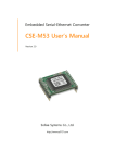
Industrial RS232↔Ethernet Converter CSE-H53 User’s Manual Version 1.7 Sollae Systems Co., Ltd. http://www.ezTCP.com CSE-H53 User’s Manual Ver. 1.7 This symbol, found on your product or on its packaging, indicates that this product should not be treated as household waste when you wish to dispose of it. Instead, it should be handed over to an applicable collection point for the recycling of electrical and electronic equipment. By ensuring this product is disposed of correctly, you will help prevent potential negative consequences to the environment and human health, which could otherwise be caused by inappropriate disposal of this product. The recycling of materials will help to conserve natural resources. For more detailed information about the recycling of this product, please contact your local city office, household waste disposal service or the retail store where you purchased this product. ※ This equipment obtained certification by using 1.5M serial cable. -1- http://www.ezTCP.com CSE-H53 User’s Manual Ver. 1.7 Contents 1 Overview ..................................................................................................................................- 5 - 1.1 Overview ................................................................................................................................................................ - 5 1.2 Main Features ...................................................................................................................................................... - 5 1.3 Application Examples ....................................................................................................................................... - 6 1.4 Components ......................................................................................................................................................... - 7 1.5 Specification ......................................................................................................................................................... - 8 - 1.5.1 Hardware ...................................................................................................................................................... - 8 1.5.2 Software ........................................................................................................................................................ - 8 1.6 Interfaces ............................................................................................................................................................... - 9 - 1.6.1 Serial Interface ........................................................................................................................................... - 9 1.6.2 Ethernet Interface .................................................................................................................................. - 10 1.6.3 Power ........................................................................................................................................................... - 10 1.7 System LED ........................................................................................................................................................ - 11 - 1.7.1 ISP Switch .................................................................................................................................................. - 11 2 Installation and Test ............................................................................................................ - 12 - 2.1 Installation .......................................................................................................................................................... - 12 - 2.1.1 Setting Network Aera .......................................................................................................................... - 12 2.2 Simple Test ......................................................................................................................................................... - 14 3 Configuration ....................................................................................................................... - 17 - 3.1 Configuration with ezManager ................................................................................................................. - 17 - 3.1.1 Configuration via LAN ......................................................................................................................... - 17 3.1.2 Configuration via Serial ...................................................................................................................... - 18 3.2 AT command ..................................................................................................................................................... - 19 4 Operation Modes ................................................................................................................ - 20 - 4.1 What is the Operation Mode? .................................................................................................................. - 20 4.2 How to entering each mode ..................................................................................................................... - 20 4.3 Comparison of each mode ......................................................................................................................... - 21 4.4 Normal Mode ................................................................................................................................................... - 21 4.5 Serial Configuration Mode ......................................................................................................................... - 22 4.6 ISP Mode ............................................................................................................................................................ - 22 - 4.6.1 Upgrading Firmware............................................................................................................................. - 22 4.6.2 Revoking Serurity Options................................................................................................................. - 22 - -2- http://www.ezTCP.com CSE-H53 User’s Manual Ver. 1.7 5 Communication Modes ...................................................................................................... - 23 - 5.1 TCP Server .......................................................................................................................................................... - 23 - 5.1.1 Key parameters ....................................................................................................................................... - 23 5.1.2 Examples .................................................................................................................................................... - 24 5.2 TCP Client ........................................................................................................................................................... - 27 - 5.2.1 Key parameters ....................................................................................................................................... - 27 5.2.2 Examples .................................................................................................................................................... - 28 5.3 AT Command .................................................................................................................................................... - 31 - 5.3.1 Key parameters ....................................................................................................................................... - 31 5.3.2 Examples .................................................................................................................................................... - 32 5.4 UDP ....................................................................................................................................................................... - 35 - 5.4.1 Key parameters ....................................................................................................................................... - 35 5.4.2 Examples .................................................................................................................................................... - 36 6 System Management .......................................................................................................... - 38 - 6.1 Upgrading Firmware ...................................................................................................................................... - 38 - 6.1.1 Firmware .................................................................................................................................................... - 38 6.1.2 Processes ................................................................................................................................................... - 38 6.2 Status Monitoring ........................................................................................................................................... - 40 - 6.2.1 Using TELNET .......................................................................................................................................... - 40 6.2.2 Using ezManager ................................................................................................................................... - 42 6.2.3 Debugging Message ............................................................................................................................ - 44 7 Additional Functions ........................................................................................................... - 47 - 7.1 Security ................................................................................................................................................................ - 47 - 7.1.1 Restriction of Access (ezTCP Firewall) .......................................................................................... - 47 7.1.2 Setting Password .................................................................................................................................... - 47 7.2 Notify IP Change ............................................................................................................................................. - 48 7.3 Sending MAC Address.................................................................................................................................. - 49 7.1 TELNET COM port Control Option (RFC 2217) ................................................................................. - 49 8 Self Test in Trouble ............................................................................................................. - 50 - 8.1 Searching problem with ezManager ...................................................................................................... - 50 8.2 Connection Problem over TCP/IP ............................................................................................................ - 51 8.3 Data Communication Problem on the Serial ..................................................................................... - 52 9 Related Material .................................................................................................................. - 53 - 9.1 Technical Documents .................................................................................................................................... - 53 - -3- http://www.ezTCP.com CSE-H53 User’s Manual Ver. 1.7 9.2 Smart phone Application ............................................................................................................................ - 53 10 Technical Support and Warranty ...................................................................................... - 54 - 10.1 Technical Support ........................................................................................................................................... - 54 10.2 Warranty .............................................................................................................................................................. - 54 - 10.2.1 Refund ......................................................................................................................................................... - 54 10.2.2 Free Repair Services ............................................................................................................................. - 54 10.2.3 Charged Repair Services..................................................................................................................... - 54 11 Precaution and Exemption from Liability ....................................................................... - 55 - 11.1 Precaution........................................................................................................................................................... - 55 11.2 Exemption from Liability .............................................................................................................................. - 56 - 11.2.1 English version ........................................................................................................................................ - 56 11.2.2 French version ......................................................................................................................................... - 57 12 History ................................................................................................................................... - 59 - -4- http://www.ezTCP.com CSE-H53 User’s Manual Ver. 1.7 1 Overview 1.1 Overview Almost all communication devices including PC are using serial transmission. In this type, devices send and receive data in the order of each byte. The serial communication is quite simple to implement but has weaknesses like short distance and hard maintenance. CSE-H53 lets the serial devices connect to the Internet. To communicate on the Internet, devices should use TCP/IP protocol, so CSE-H53 processes the converting serial data to TCP/IP. 1.2 Main Features RS232 (D-sub 9pin Male, speed up to 230.4Kbps) Industrial temperature range (-40℃ ~ +85℃) Variety of monitoring status (debugging mode, ezManager, TELNET) -5- http://www.ezTCP.com CSE-H53 User’s Manual Ver. 1.7 1.3 Application Examples 1:1 Connection with a PC Fig 1-1 1:1 connection with a PC Applied to LANs Fig 1-2 applied to LANs -6- http://www.ezTCP.com CSE-H53 User’s Manual Ver. 1.7 Applied to the Internet on Cable Networks Fig 1-3 applied to the Internet on cable networks Applied to the Internet with an IP Share Router Fig 1-4 applied to the Internet with an IP share router 1.4 Components CSE-H53’s Body RS232 Cross Cable (Option) DC 5V Power Adapter (Option) -7- http://www.ezTCP.com CSE-H53 User’s Manual Ver. 1.7 1.5 Specification 1.5.1 Hardware Power Input Voltage DC 5V (±10%) Current 120mA typical Dimension 87mm x 57mm x 24mm Weight About 65g RS232 – RTS/CTS and Xon/Xoff Flow Control Serial (Baud Rate: 300bps ~ 230,400bps) Serial Port 10 Base-T or 100 Base-TX Ethernet Auto-Sensing Network Auto MDI or MDIX cable Auto-Sensing Temperature Storage / Operating Temperature: -40 ~ 85℃ Certification CE: F690501/SP-EMY000240 / MIC: SLS-CSE-H53 (A) RoHS RoHS Compliant Table 1-1. Hardware specification 1.5.2 Software Protocol TCP, UDP, IP, ICMP, ARP, DHCP, PPPoE, Telnet, DNS Lookup, DDNS, TELNET COM port Control Option (RFC 2217) Diagnose Online Debugging Function Normal For Normal Data Communication ISP For Upgrading F/W Serial Configuration For Configuration via Serial TCP Server TCP Passive Connection Communicat TCP Client TCP Active Connection ion mode AT Command TCP Passive / Active Connection UDP UDP – No Connection Operation mode Major Utilities ezManager ezVSP Configuration Utility for MS Windows (Supports Downloading F/W) Serial to TCP/IP Virtual driver for MS Windows Table 1-2. Software specification -8- http://www.ezTCP.com CSE-H53 User’s Manual Ver. 1.7 1.6 Interfaces 1.6.1 Serial Interface CSE-H53 has an RS232 port for user serial device (300bps ~ 230,400bps). CSE-H53 converts serial data from user device to TCP/IP and transmits to Ethernet port. Fig 1-5 9 pins D-sub Male connector Pin Assignment Number Name Description Level I/O Etc. 1 DCD Data Carrier Detect RS232 IN N/C 2 RXD Receive Data RS232 IN required 3 TXD Transmit Data RS232 OUT required 4 DTR Data Terminal Ready RS232 OUT optional 5 GND Ground Ground - required 6 DSR Data Set Ready RS232 IN optional 7 RTS Request To Send RS232 OUT optional 8 CTS Clear To Send RS232 IN optional 9 RI Ring Indicator RS232 IN N/C Table 1-3 pin assignment of the RS232 port N/C: Not Connected -9- http://www.ezTCP.com CSE-H53 User’s Manual Ver. 1.7 1.6.2 Ethernet Interface Since part of CSE-H53 network is composed of Ethernet, UTP cable may be connected. It will automatically sense 10Mbits or 100Mbits Ethernet and connect itself. It also provides auto MDI/MDIX function that can automatically sense 1:1 cable or cross over cable. Each Ethernet device has its own unique hardware address. The hardware address of CSEH53 is set in the factory before being shipped to the market. (The hardware address is also known as the MAC address) Fig 1-6 RJ45 the Ethernet interface 1.6.3 Power DC5V is used for the power. The specifications of the power jack are as the following: Fig 1-7 power - 10 - http://www.ezTCP.com CSE-H53 User’s Manual Ver. 1.7 1.7 System LED CSE-H53 has several lamps to show the current system status. Each lamp shows the following status: Mode Common Name Color Status Description PWR Red On Supplying the power LINK Green On Connecting with Ethernet RXD Yellow Blinks Receiving data from the Ethernet TXD Green Blinks Sending data to the Ethernet Blinks in every Normal mode ISP mode Serial Configuration mode STS STS Yellow Yellow Obtaining an IP address second Blinks 4 times Without obtaining an IP address at once under DHCP or PPPoE network Off Entering ISP mode STS LINK /RXD - Blinks simultaneously Entering Serial Configuration mode /TXD Table 1-4 status of the system LED 1.7.1 ISP Switch There is a switch, which is named ISP switch (or button) located on the side of the product. You can change the operation mode of CSE-H53 to ISP or Serial Configuration mode with this switch. Fig 1-8 ISP switch - 11 - http://www.ezTCP.com CSE-H53 User’s Manual Ver. 1.7 2 Installation and Test 2.1 Installation Before testing CSE-H53, users should connect both serial and Ethernet port to a PC. It will be no problem that the Ethernet connection includes network hubs. Fig 2-1 connection between CSE-H53 and a PC Procedures for the test are followed. 2.1.1 Setting Network Aera This step is for setting both CSE-H53 and users’ PC to be located the same network. If only they are, the TCP connection between them can be established. Setting of the PC Add or change the IP address of the network adapter on your PC like following. Get into the menu of [Windows Control Panel] >> [Network Connections] >> [Properties of the Network Adapter – with right click of your mouse]. Then, you can show the properties of [Internet Protocol (TCP/IP). In there, press the [Advanced..] button for adding an IP Address like the below figure. Fig 2-2 adding / changing the IP address of users’ PC - 12 - http://www.ezTCP.com CSE-H53 User’s Manual Ver. 1.7 Setting of CSE-H53 CSE-H53 uses ezManager as it’s a configuration program. ezManager is for MS Windows, and this is comfortable to use because it doesn’t need installation. First, search your CSE-H53 via network. All the values of parameters are set the default values in the factory. To apply it to your system, proper values should be set via ezManager. Major parameters’ default values are listed on below table. To implement this simple test, keep these values without any changes. Name Default Values Local IP Address 10.1.0.1 Subnet Mask 255.0.0.0 TELNET Checked IP Address Search Checked Serial Type RS232 Baud Rate 19,200bps Parity NONE Serial Port Data Bits 8 (COM1) Stop Bit 1 Flow Control NONE Communication mode TCP Server Local Port 1470 Network Option Table 2-1 default values of Major parameters Users can download the latest version of ezManager on the [Download] >> [Technical Documents] menu of our website. - 13 - http://www.ezTCP.com CSE-H53 User’s Manual Ver. 1.7 2.2 Simple Test If you press the [Simple Test] button, test program will be shown on your screen. Connecting to the CSE-H53 via LAN Fig 2-3 settings for TCP connection ① Select [TCP Client] ② Input correct IP address and port number of CSE-H53 ③ Clink the [Connect] button. (In case of TCP Server, it will be [Listen] button) Opening RS232 Port Fig 2-4 opening COM Port ④ Select COM port which the CSE-H53 is connected to ⑤ Make sure that all the parameters are the same with CSE-H53 ⑥ Press the [Open] button - 14 - http://www.ezTCP.com CSE-H53 User’s Manual Ver. 1.7 Confirm the TCP Connection and COM port status Fig 2-5 TCP Connected message ⑦ Check the message if the TCP connection is established Fig 2-6 COM Port open message ⑧ Check the message if the COM port has been opened - 15 - http://www.ezTCP.com CSE-H53 User’s Manual Ver. 1.7 Data transmission test Fig 2-7 successful data transmission ⑨ Click the [Send data] on the LAN part ⑩ Check the data have been shown from the step ⑨ Fig 2-8 LAN → RS232 ⑪ Press the [Send data] on the RS232 part ⑫ Check the data have been received from the step ⑪ Fig 2-9 RS232 → LAN - 16 - http://www.ezTCP.com CSE-H53 User’s Manual Ver. 1.7 3 Configuration 3.1 Configuration with ezManager Fig 3-1 initial appearance of ezManager 3.1.1 Configuration via LAN Checklists Make sure the connection between your PC and CSE-H53. If they are the same network, [MAC Address search] button can be used. If they aren’t, only [IP Address search] is allowed to use. Procedures Fig 3-2 procedures for configuration via LAN - 17 - http://www.ezTCP.com CSE-H53 User’s Manual Ver. 1.7 3.1.2 Configuration via Serial Checklists Make sure the connection between your PC and CSE-H53 using RS232 cross cable. To use this, CSE-H53 has to be operating in the [Serial Configuration] mode. By pressing the ISP button less than 1 second, you can enter the mode. After this, read the setting via [Serial] tab on ezManager. Procedures Fig 3-3 procedures for configuration via Serial Step 2, Reading Fig 3-4 reading procedure via serial ② Choose the [Serial] tab ② Select the COM port which the CSE-H53 is connected with ③ Open the COM port with the [Open] button ③ Load the setting with [Read] button If you want to know more specific manners of setting, please refer to the document “ezManager Users’ Manual” on the [Download] >> [Technical Document] of our website. - 18 - http://www.ezTCP.com CSE-H53 User’s Manual Ver. 1.7 3.2 AT command In the AT command mode, you can change some parameters through the serial port. Checklists Make sure the connection between your PC and CSE-H53 using RS232 cross cable. To use this, CSE-H53 has to be set to [AT command] mode as its communication mode. This can be configured by ezManager. Fig 3-5 setting the communication mode to the AT command Procedures Fig 3-6 procedures for configuration with AT command Division IP Address related items TCP connection related items Option Available parameters Local IP Address, DHCP, PPPoE, Subnet Mask, Gateway IP Address, DNS IP Address, ··· Local Port, Peer Address (IP Address or Host name), Peer Port, ··· ESC code sending option, timeout, ··· Table 3-1 parameters which are available to change with AT command Including above items, rest of parameters can be set by ezManager - 19 - http://www.ezTCP.com CSE-H53 User’s Manual Ver. 1.7 4 Operation Modes 4.1 What is the Operation Mode? Each of three operation mode of CSE-H53 is defined for specific purpose, and those are followed. Normal mode This mode is for normal data communication and has 4 different connection modes. Configuring parameters is also available in this mode. Serial configuration mode This mode is for configuring environmental parameters through the RS-232 port. ISP mode This mode is for upgrading firmware. In addition, you can set environmental parameters even though the security options like password are activated by entering this mode. 4.2 How to entering each mode Fig 4-1 How to entering each mode - 20 - http://www.ezTCP.com CSE-H53 User’s Manual Ver. 1.7 4.3 Comparison of each mode Table 4-1 shows summaries of each mode Name Normal Serial Configuration ISP Entering Serial port Configured Supply the power. value Press the ISP button shortly between 10ms and 1s. Supply the power with pressing the ISP button or 115200/N/8/1 115200/N/8/1 press the ISP button over 1 sec, in other modes. Table 4-1 Comparison of each mode 4.4 Normal Mode In normal mode, there are four connection types to communication with a remote host. TCP Server TCP Client AT Command UDP Modifying Name Protocol Connection software of serial devices TCP Server TCP Client TCP AT Command UDP UDP Serial configuration Topology Passive - Unavailable 1:1 Active - Unavailable 1:1 Either Required Available 1:1 - - Unavailable N:M Table 4-2 Comparison of four communication modes TCP is a type of protocol, which has a process of connection. The connection has to be one to one. The part who tries to make the connection is called TCP Client, and the other part is TCP Server. On the other hand, UDP has no connection process. Because of this, each of them can be send and receive data from multiple hosts. - 21 - http://www.ezTCP.com CSE-H53 User’s Manual Ver. 1.7 4.5 Serial Configuration Mode This is a mode for setting environmental parameters through RS232 port. If you can’t use the Ethernet, this mode is only way to configure the values. Once entering this mode, use the [Read] button on the [Serial] tab of ezManager. 4.6 ISP Mode You can enter this mode by pressing the ISP button over 1 second. There are two special purposes in this mode. 4.6.1 Upgrading Firmware ISP mode is for upgrading firmware which is offered by us. The upgrade is implemented on Ethernet. The details are followed in the “6.1 Upgrading Firmware”. 4.6.2 Revoking Serurity Options CSE-H53 offers restriction methods for security like filtering password or MAC and IP address. In the ISP mode, you can revoke all of these. When you forgot the password, enter the ISP mode to solve the problem. - 22 - http://www.ezTCP.com CSE-H53 User’s Manual Ver. 1.7 5 Communication Modes 5.1 TCP Server In this mode, CSE-H53 functions as a TCP server. CSE-H53 listens to a TCP connection from remote host. Once a host tries to connect to CSE-H53, it responses that request. After the connection is established, CSE-H53 converts the raw data from the serial port to TCP/IP data and sends them to the network and vice versa. 5.1.1 Key parameters Local Port This is a server’s port number which is used in the TCP connection. Event Byte With setting event bytes, users can handle the serial data before a TCP connection is established. Value 0 Otherwise (512 or under) Description CSE-H53 doesn’t send the data CSE-H53 sends the data right after a connection is established. 512 or under bytes are strongly recommended. Table 5-1 Event Byte Timeout If there is no transmission of data for amount of time which is set to this parameter, CSE-H53 tries to terminate established TCP connection. Notify IP Change This function is for notifying information about changed IP address to a server. Not only the TCP/UDP protocol but Dynamic Domain Name Service (DDNS) can be used. Restriction of Access Users can block TCP connections from unauthorized hosts by using this option. Both IP and MAC address are available. - 23 - http://www.ezTCP.com CSE-H53 User’s Manual Ver. 1.7 5.1.2 Examples A situation that [Event Byte] is set to 0. Fig 5-1 time chart for a situation that [Event Byte] is set to zero Points States ~ CSE-H53 is listening to connection requests ① Remote host has sent a connection request (SYN) segment ~ Processes of the connection ② The connection has been established ~ Data communication on both sides Table 5-2 states of Fig 5-1 Look at the blue arrow. The data “123” from the serial port had sent before the connection is established. In this case, the data wasn’t sent because of the [Event Byte] is set to 0 - 24 - http://www.ezTCP.com CSE-H53 User’s Manual Ver. 1.7 A situation that [Event Byte] is set to 1. Fig 5-2 time chart for a situation that [Event Byte] is set to 1 Points States ~ CSE-H53 is listening to connection requests ① Remote host has sent a connection request (SYN) segment ~ Processes of the connection ② The connection has been established ~ The data “123” has been sent right after the end of connection processes Table 5-3 states of Fig 5-2 As you can see, the data “123” has been sent right after the connection is established because the value of [Event Byte] had been set to 1. If the value is not 0, the result is the same as above example. - 25 - http://www.ezTCP.com CSE-H53 User’s Manual Ver. 1.7 A situation that [Timeout] is set to 5. Fig 5-3 time chart for a situation that [Timeout] is set to 5 Points States ~ Data communication on both sides ① The last segment has been arrived at the CSE-H53 ~ 5 seconds are passed with no data communication ② CSE-H53 has sent disconnection request (FIN) to a remote host ~ Processes of the disconnection ③ The connection has been terminated ~ CSE-H53 is listening to connection requests Table 5-4 states of Fig 5-3 - 26 - http://www.ezTCP.com CSE-H53 User’s Manual Ver. 1.7 5.2 TCP Client In this mode, CSE-H53 functions as a TCP client. CSE-H53 sends request segments to a remote host with information of [Peer Address] and [Peer Port]. Once a host is listening and works correctly, the connection will be established. After then, CSE-H53 converts the raw data from the serial port to TCP/IP data and sends them to the network and vice versa. 5.2.1 Key parameters Peer Address This item should be an address of a remote host who is listening TCP connections. Peer Port [Peer Port] should be the port number which is designated by the remote host. Event Byte CSE-H53 decides the time to send the connection request frame with this parameter. Value 0 Otherwise (512 or under) Description Right after CSE-H53 boots up right after the bytes set to [Event Byte] have been received from the serial port Setting to less than 512 bytes is strongly recommended. Table 5-5 the operation of Event Byte 1 In addition, users can handle the serial data before a TCP connection is established with this parameter. Value 0 Otherwise (512 or under) Description CSE-H53 doesn’t send the data CSE-H53 sends the data right after a connection is established. Setting to less than 512 bytes is strongly recommended. Table 5-6 the operation of Event Byte 2 Timeout If there is no transmission of data for amount of time which is set to this parameter, CSE-H53 tries to terminate established TCP connection. TCP Server This check option is enable the TCP server / client mode. In this mode, CSE-H53 can be operated as a TCP server or client without changing its setting. DNS IP Address [DNS IP Address] needs when you use host name instead of the IP address. - 27 - http://www.ezTCP.com CSE-H53 User’s Manual Ver. 1.7 5.2.2 Examples A situation that [Event Byte] is set to 0. Fig 5-4 time chart for a situation that [Event Byte] is set to 0 Points States ~ Before the power is supplied ① Sends TCP connection request segment right after it boots up ~ Processes of the disconnection ② The connection has been established ~ Data communication on both sides Table 5-7 states of Fig 5-4 Look at the blue arrow. The data “123” from the serial port had sent before the connection is established. In this case, the data wasn’t sent because of the [Event Byte] is set to 0 - 28 - http://www.ezTCP.com CSE-H53 User’s Manual Ver. 1.7 A situation that [Event Byte] is set to 5. Fig 5-5 time chart for a situation that [Event Byte] is set to 5 Points ~ States CSE-H53 has receives data from its serial port until the amount of data is 5 bytes ① Sends connection request segment right after receiving 5 bytes. ~ Processes of the TCP connection ② The connection has been established ~ The “1234567” is transmitted to the remote host Table 5-8 states of Fig 5-5 As you can see in the figure 5-5, CSE-H53 sends request segment right after the serial data had been 5 bytes. Even though those are come before the connection is established, the data “123”, “45” and “67” are transmitted to the remote host because of the [Event Byte] is set to 5. - 29 - http://www.ezTCP.com CSE-H53 User’s Manual Ver. 1.7 An activated [TCP Server] option Fig 5-6 time chart for activating [TCP Server] option Points States ~ CSE-H53 is listening to connection requests ① The connection has been established ~ CSE-H53 is on line and processes of the disconnection ② The connection has been terminated ~ Both sides are offline ③ Sends TCP connection request segment Table 5-9 states of Fig 5-6 The TCP Server / Client mode can be useful option by using [Event Byte] and [Timeout]. Note that only one TCP connection can be established at the same time, so users should consider setting [Timeout] properly. - 30 - http://www.ezTCP.com CSE-H53 User’s Manual Ver. 1.7 5.3 AT Command AT command is a mode which users control CSE-H53 with AT command like controlling modem. In this mode, active and passive TCP connections are available. And users are allowed to configure some environmental parameters with extended commands. 5.3.1 Key parameters The configuration should be implemented via the serial port of CSE-H53 Commands Description Examples +PLIP Local IP Address AT+PLIP=10.1.0.1<CR> +PLP Local Port AT+PLP=1470<CR> +PRIP Peer IP Address AT+PRIP=10.1.0.2<CR> +PRP Peer Port AT+PRP=1470<CR> +PDC DHCP AT+PDC=1 (ON)<CR> +PPE PPPoE AT+PPE=1 (ON)<CR> +PTO Timeout AT+PTO=10<CR> +PWP Store setting AT+PWP<CR> Table 5-10 some of extended commands for configuration Related items with IP Address and Local Port Local port can be set as well as IP address related parameters like IP Address, Subnet Mask and Gateway IP Address. Peer Address / Peer Port IP address and local port of a remote host are can be set. Type of assigning IP address: Manual, DHCP, PPPoE Not only manual setting, also automatic assigning protocol (DHCP, PPPoE) are available. Others Some of options including [Timeout] can be configured in this mode. - 31 - http://www.ezTCP.com CSE-H53 User’s Manual Ver. 1.7 5.3.2 Examples TCP Server – setting parameters and passive connection Fig 5-7 TCP passive connection Points ~ ① States Set parameters in the AT command mode CSE-H53 listens TCP connection requests with the ATA command ~ CSE-H53 is listening TCP connection requests ② A remote host has sent SYN segment to CSE-H53 ~ Processes of TCP connection ③ TCP connection has been established ~ CSE-H53 sends “CONNECT” message to the serial port Table 5-11 states of Fig 5-7 Most of the response messages from the serial port of CSE-H53 are omitted on above figure. - 32 - http://www.ezTCP.com CSE-H53 User’s Manual Ver. 1.7 TCP Client – setting parameters and active connection Fig 5-8 TCP Active connection Points ~ ① States Set parameters in the AT command mode CSE-H53 sends a TCP connection request with the ATD command ~ Processes of TCP connection ② TCP connection has been established ~ CSE-H53 sends “CONNECT” message to the serial port Table 5-12 states of Fig 5-8 - 33 - http://www.ezTCP.com CSE-H53 User’s Manual Ver. 1.7 Termination of online status – entering the AT command mode Fig 5-9 Termination of online status Points States ~ Keeps TCP connection ① CSE-H53 enters the AT command mode with receiving “+++” ~ Keeps AC command mode ② CSE-H53 terminates TCP connection with ATH command ~ Processes of TCP disconnection ③ TCP connection has been terminated ~ CSE-H53 sends “NO CARRIER” with disconnection Table 5-13 states of Fig 5-9 CSE-H53 changes the mode to AT command, when receiving “+++” and sending “OK” message. In this state, the communication with remote host is not possible because CSEH53 processes only AT command. Whenever you want to go back to online state (TCP connection), use “ATO” command. For more information about this, please refer to the “ATC mode” on the [Download] >> [Technical Document] menu of our web site. - 34 - http://www.ezTCP.com CSE-H53 User’s Manual Ver. 1.7 5.4 UDP UDP has no processes of connection. In this mode, data is sent in block units. Therefore, data that comes through CSE-H53’s serial port must be classified in block units to send it elsewhere. 5.4.1 Key parameters Block Size(Byte) [Block Size(Byte)] means the size of a block in UDP mode. Its unit is byte. The size of bytes are come into the serial port, CSE-H53 sends them as one block to the network. The maximum value could be 1,460 bytes. Data Frame [Data Frame] means the time for gathering data to make one block. Its unit is 10ms. If there are no transmission during the time which is set to this value, CSE-H53 sends gathered data in the buffer as one block to the network. Once one of the parameters is sufficient, the block size is decided as the condition. Dynamic update of Peer host If users set the value of [Peer Address] and [Peer Port] to 0, [dynamic update of peer host] function is activated. By using this function, CSE-H53 can communicate to multiple hosts without additional setting. - 35 - http://www.ezTCP.com CSE-H53 User’s Manual Ver. 1.7 5.4.2 Examples Block Size: 5 bytes / Data Frame: 1s (100 by 10ms) Fig 5-10 time chart for event byte is 5 bytes and data frame is 1s Points ~ ① States CSE-H53 is receiving data from the serial port CSE-H53 Sends 5 bytes as one block based on the [Event byte] ~ Serial device sends data “678” to the CSE-H53 ② Data “678” has arrived ~ CSE-H53 sends data from the remote host to the serial device ③ 1 second has passed ~ CSE-H53 sends data “678” based on the [Data frame] Table 5-14 states of Fig 5-10 - 36 - http://www.ezTCP.com CSE-H53 User’s Manual Ver. 1.7 Dynamic Update of Peer host This is a function that CSE-H53 automatically sets its peer host with information of the last packet which is received from network. In the packet, the source address and port number is used. Parameters Values Peer Address 0 (None) Peer Port 0 Table 5-15 setting for [dynamic update of peer host] function Fig 5-11 time chart for [dynamic update of peer host] Points States ~ Remote host 2 sends data to CSE-H53 ① CSE-H53 sets host 2 to peer host ~ Remote host 1 sends data to CSE-H53 ② CSE-H53 updates host 1 to peer host ~ Remote host 2 sends data again to CSE-H53 ③ CSE-H53 updates host 2 to peer host ~ CSE-H53 can communicate with remote host 2 Table 5-16 states of Fig 5-11 The data “ABC”, “DE”, “FGH” are from the serial port of CSE-H53 in the Fig 5-11. - 37 - http://www.ezTCP.com CSE-H53 User’s Manual Ver. 1.7 6 System Management 6.1 Upgrading Firmware 6.1.1 Firmware Firmware is a type of software for operation of CSE-H53. If there are needs for adding function or fixing bugs, the firmware is modified and released. We recommend that users keep use the latest released firmware. 6.1.2 Processes Downloading the latest released firmware Download the newest firmware file. We update our homepage when a new firmware is released. You can find it on our website. Entering ISP mode Enter ISP mode to download firmware file to CSE-H53. Run a TFTP client and ready to send the F/W file Run a TFTP client program. ezManager is equipped the client program. Click the [Change F/W / HTML] button. Fig 6-1 running TFTP client ① Check the [Advanced Menu] check box ② Click the [Change F/W / HTML] button to run TFTP client ③ Select the [Change Firmware] radio button ④ Input the IP address of CSE-H53 to the [Local IP Address] text box ⑤ Press the [Open Firmware / HTML] button and choose the firmware file - 38 - http://www.ezTCP.com CSE-H53 User’s Manual Ver. 1.7 Checking firmware file and Sending Fig 6-2 sending firmware file ① Check if the name and path of the firmware file are correct ② Click the [Send] button ③ Confirm the completed message - 39 - http://www.ezTCP.com CSE-H53 User’s Manual Ver. 1.7 6.2 Status Monitoring 6.2.1 Using TELNET Once the [TELNET] option is activated, users can remotely log in to CSE-H53. If a password is set, users should input the password. After then, messages from CSE-H53 appear like Fig 6-3. Fig 6-3 log in to CSE-H53 on TELNET Followed commands let users check each state. Command st sc Option Description Usage net Network Status lsh>st net sio Serial Port Status lsh>st sio uptime System Uptime lsh>st uptime [OP1][OP2] Session Control lsh>sc com1 close Table 6-1 Commands for checking states st net “st net” command displays present network states of all sessions. Fig 6-4 “st net” command - 40 - http://www.ezTCP.com CSE-H53 User’s Manual Ver. 1.7 st sio “st sio” command displays the number of bytes for the serial port. Fig 6-5 “st sio” command st uptime “st uptime” command shows amount of time since CSE-H53 boots up. Fig 6-6 “st uptime” command sc “sc” command is used when users close a session. [OP1] means the name of session, and [OP2] should be “close”. Fig 6-7 “sc” command In case of the “sc” command you should use only small letters. - 41 - http://www.ezTCP.com CSE-H53 User’s Manual Ver. 1.7 6.2.2 Using ezManager Status of CSE-H53 can be monitored by [Status] button on ezManager. By using the [Refresh Every 1 Second] option in the status window, the status is automatically updated in every second. Fig 6-8 status window of ezManager FIRMWARE VERSION The name of model name and the version of firmware are displayed here. SYSTEM UPTIME Amount of time is displayed since CSE-H53 boots up. IP4 NETWORK INFORMATION All information about related items with IP Address is shown here. It works even if the IP address is assigned from DHCP or PPPoE. - 42 - http://www.ezTCP.com CSE-H53 User’s Manual Ver. 1.7 TCP STATE TCP status of each port is shown this section. Message Description LISTEN listening TCP connection CLOSE TCP connection is closed SYN_SENT ESTABLISHED N/A Send “SYN” segment to make TCP connection When TCP connection is established In UDP mode Table 6-2 TCP STATE SERIAL STATUS Amount of data in every buffer is displayed. The unit is byte. Buffer Description sio_rx The number of data which is received from the COM port net_tx The number of data which is sent to the remote host net_rx The number of data which is received from the remote host sio_tx The number of data which is sent to the COM port Table 6-3 SERIAL STATUS ARP TABLE This part shows ARP table on CSE-H53. When TCP connection is established or UDP data communication is performed, the information of IP and MAC address is automatically stored in the ARP table. This information is held for 1 minute. When 50 seconds is passed, CSE-H53 starts broadcasting the ARP packet again. If there is no response until the time is 0, the information is removed. If there is response, the time is updated 60 seconds again. TCP/IP Connection In this section, the same information with TCP STATE is displayed with IP address and port number. A difference is that users can terminate TCP connection. When right click on a session, a small pop-up window is created. Password This text box is activated when CSE-H53 has a password. If users want to close TCP connection with right click of mouse on the session, this password has to be correctly filled. Refresh Every 1 Second. If this option is checked, ezManager send query in every second. - 43 - http://www.ezTCP.com CSE-H53 User’s Manual Ver. 1.7 6.2.3 Debugging Message By using [Debugging] option, users can receive debugging messages from CSE-H53 on the network. Setting debugging option Fig 6-9 setting debugging option ① Check the [Debugging Message] option ② Press the [Write] button ③ After check the [Advanced Menu], click the [Debugging Message] button. And then, the debugging message window is shown on your screen like figure 6-10. - 44 - http://www.ezTCP.com CSE-H53 User’s Manual Ver. 1.7 Fig 6-10 debugging message window ① Network Adapter ② Place for listing received debugging messages from CSE-H53 over the network ③ Auto update to display the latest captured file on the screen of ② ④ MAC Address and Serial port Information of a selected message ⑤ Amount of received or dropped data and XON/OFF signals ⑥ Serial port’s receiving status with LED interface ⑦ Place for listing received data from the serial port ⑧ Buttons for saving, closing and clearing a log file including an auto scroll option ⑨ Serial port’s transmitting status with LED interface ⑩ Place for listing sent data to the serial port ⑪ Buttons for saving, closing and clearing a log file including an auto scroll option ⓐ To start capturing debugging messages from CSE-H53 ⓑ To stop capturing debugging messages from CSE-H53 - 45 - http://www.ezTCP.com CSE-H53 User’s Manual Ver. 1.7 ⓒ [Reboot] button is for software rebooting ⓓ [Load Message] is for loading a debugging log file to display ⓔ Closing debugging message window If you have problems with communication or connection, it can be helpful for us that you capture the debugging messages and send us to the file. When you use [Debugging Message] function, it can cause network traffic because the messages are broadcasted to whole network. If you don’t use it anymore, you should uncheck the function. - 46 - http://www.ezTCP.com CSE-H53 User’s Manual Ver. 1.7 7 Additional Functions 7.1 Security 7.1.1 Restriction of Access (ezTCP Firewall) On the [Option] tab of ezManager, users can set restriction of access function with filtering MAC and IP address. Allowed MAC Address If this option has a value of MAC address, the device which has the MAC address is only permitted to access. Allowed IP Address This is for qualifying hosts with IP address or range of IP address. The range is defined by multiplying [IP address] and [Network Mask] in bit unit. Examples IP Address Network Mask Allowed IP Address Range 10.1.0.1 255.0.0.0 10.1.0.1 ∼ 10.255.255.254 10.1.0.1 255.255.255.0 10.1.0.1 ∼ 10.1.0.254 192.168.1.4 255.255.255.255 192.168.1.4 Fig 7-1 examples of defining allowed IP range Apply to ezManager [Apply to ezManager] is for applying above two restrictions to ezManager functions like [Search], [Read], [Write] and etc. 7.1.2 Setting Password A password can be used for protecting CSE-H53 from TELNET login or changing environmental parameters by hosts which are not qualified. The maximum length is 8 bytes of Alphabet or number. When you want to revoke all of these restrictions, operate CSE-H53 as ISP mode. In the mode, all restrictions are removable and communication with ezManager is revoked. - 47 - http://www.ezTCP.com CSE-H53 User’s Manual Ver. 1.7 7.2 Notify IP Change CSE-H53 can be TCP server even though it assigned IP address automatically. Using [Notify IP Change] function, CSE-H53 sends its IP address with the host name to the designed server. There are 3 types- DDNS, TCP and UDP- for this service. Dynamic Domain Name Service (DDNS) CSE-H53 supports DDNS service offered by DynDNS. Therefore, you have to make an account and create host names on the website of DynDNS before you use. All about service usage of an account could be changed according to the policy of DynDNS. Homepage of DynDNS: http://dyn.com/ Fig 7-1 setting DDNS ① Select the [DDNS(dyndns.org)] ② 40,320 is a fixed value ③ Input the ID of DDNS account ④ Input the password of the account ⑤ Input a host name which you create on your account TCP/UDP In case you have an own server and want to manage the information about changed IP addresses, you allowed used TCP/UDP for using this option. The [Data Type] can be selected as ASCII or hexadecimal, and the [Interval] is available on configuration. - 48 - http://www.ezTCP.com CSE-H53 User’s Manual Ver. 1.7 7.3 Sending MAC Address [Sending MAC Address] is a function that CSE-H53 sends its MAC address to the remote host right after the connection is established. By using this function, a server can identify multiple devices with the information. Fig 7-2 setting of Sending MAC Address function ① Move to the [Option] tab. ② Check the [Send MAC Address] option. 7.1 TELNET COM port Control Option (RFC 2217) This option is for sending and receiving serial port states between two devices. Users can send and receive control signals like RTS/CTS when the states are changed. Fig 7-3 setting of TELNET COM Port Control option ① Move to the [Serial Port] tab. ② Check the [Telnet COM Port Control (RFC2217)] option. If you want details about the [TELNET COM port Control Option] and [Sending MAC Address], please refer to the documents on the [Download] >> [Technical Document] of our website. - 49 - http://www.ezTCP.com CSE-H53 User’s Manual Ver. 1.7 8 Self Test in Trouble When users are in trouble with CSE-H53, make sure all the followed steps first. 8.1 Searching problem with ezManager Confirming types of configuration utility CSE-H53 can be configured by ezManager. Stopping Firewall operation Firewalls of personal computer or network block broadcast packets. Stop all the firewalls before searching CSE-H53 Most of vaccine programs have firewall functions so it can cause some trouble to search CSE-H53. Stop these programs before the searching. Stable supply of the power Check if the power is supplied continually. If the power is constantly supplied, the PWR (Red) LED on the CSE-H53’s body will be turned ON. Connection with the network Make sure that the network connection is fine including Ethernet cable. In this step, we recommend that users connect CSE-H53 with PC directly or in the same network hub. Checking options of restriction In case that restriction of access is activated, the communication with ezManager can be impossible. When users are in this situation, make CSE-H53 operate in ISP mode. - 50 - http://www.ezTCP.com CSE-H53 User’s Manual Ver. 1.7 8.2 Connection Problem over TCP/IP Checking parameters related with TCP/IP When CSE-H53 has a private network IP address, personal computer’s IP address has to be the same sub network. Check if the IP address and local port number are correct. In case of a fixed IP address, the subnet mask, gateway IP address and DNS IP address should be configured. TCP Server side TCP Client side Local IP Address, Local Port, Subnet Local IP Address, Peer Address, Peer Port, Mask, Gateway IP Address, DNS IP Subnet Mask, Gateway IP Address, DNS IP Address, DDNS option Address, Table 8-1 major parameters related with TCP/IP PING Test Confirm the connection over the network by PING test. If the CSE-H53 doesn’t send any reply from the request, check the network environment. Firewall In case the networks which need strong security, the access may be denied by their firewall. Under this circumstance, users should ask the person in charge of their network to release ports which will be used. (Ex: TCP 1470, UDP 50005) Operation Mode TCP connection is not possible when CSE-H53 is operating in the ISP or Serial Configuration mode. Communication Mode To make TCP connection, both a server and client should exist. If there are only servers or clients, TCP connection can’t be established. ezTCP Firewall When users set the ezTCP firewall with MAC and IP address, any hosts can’t be reachable to it except for the hosts which have the allowed MAC and IP address. Inactivate the option or check the setting is correct. Checking the TCP status TCP is a protocol connected one to one without multiple connection function. Because of this, if a device is on TCP connection, other requests are denied. If users are in this situation, check the network status by connecting on TELNET or using ezManager. - 51 - http://www.ezTCP.com CSE-H53 User’s Manual Ver. 1.7 8.3 Data Communication Problem on the Serial Connection of Pins Check if the connection of each pin is right. Using cables, users choose the right type of cable which is suitable for the device. Transmit Data (TXD) pin should be connected with Receive Data (RXD) pin. Look at the figure 8-1. Fig 8-1 RS232 connection Setting parameters Check if all the serial port parameters like Baud Rate, Data bit, Stop bit and Parity are properly set. Contact us if you have any questions about above steps or our products. - 52 - http://www.ezTCP.com CSE-H53 User’s Manual Ver. 1.7 9 Related Material 9.1 Technical Documents You can find the technical documents at our website. DataSheet IP Change Notification(DDNS) Sending MAC Address function TCP Server/Client mode Telnet COM Port Control Option etc 9.2 Smart phone Application ezManager(IOS) ezManager(Android) TCP/IP Client(Android) - 53 - http://www.ezTCP.com CSE-H53 User’s Manual Ver. 1.7 10 Technical Support and Warranty 10.1 Technical Support If you have any question regarding operation of the product, visit Customer Support FAQ corner and the message board on Sollae Systems’ web site or send us an email at the following address: E-mail: [email protected] Website Address for Customer Support: http://www.eztcp.com/en/support/ 10.2 Warranty 10.2.1 Refund Upon the customer’s request to refund the product within two weeks after purchase, Sollae Systems will refund the product. 10.2.2 Free Repair Services For product failures occurring within 2 years after purchase, Sollae Systems provides free repair services or exchange the product. However, if the product failure is due to user’s fault, repair service fees will be charged or the product will be replaced at user’s expense. 10.2.3 Charged Repair Services For product failures occurring after the warranty period (2 years) or resulting from user’s fault, repair service fees will be charged and the product will be replaced at user’s expense. - 54 - http://www.ezTCP.com CSE-H53 User’s Manual Ver. 1.7 11 Precaution and Exemption from Liability 11.1 Precaution Sollae Systems is not responsible for product failures occurring due to user ’s alternation of the product. Specifications of the product are subject to change without prior notice for performance improvement. Sollae Systems does not guarantee successful operation of the product if the product was used under conditions deviating from the product specifications. Reverse engineering of firmware and applications provided by Sollae Systems is prohibited. Use of firmware and applications provided by Sollae Systems for purposes other than those for which they were designed is prohibited. Do not use the product in an extremely cold or hot place or in a place where vibration is severe. Do not use the product in an environment in which humidity is high or a lot of oil exists. Do not use the product where there is caustic or combustible gas. Sollae Systems does not guarantee normal operation of the product under the conditions a lot of noise exists. Do not use the product for a purpose that requires exceptional quality and reliability relating to user’s injuries or accidents – aerospace, aviation, health care, nuclear power, transportation, and safety purposes. Sollae Systems is not responsible for any accident or damage occurring while using the product. - 55 - http://www.ezTCP.com CSE-H53 User’s Manual Ver. 1.7 11.2 Exemption from Liability 11.2.1 English version In no event shall Sollae Systems Co., Ltd. and its distributors be liable for any damages whatsoever (including, without limitation, damages for loss of profit, operating cost for commercial interruption, loss of information, or any other financial loss) from the use or inability to use the CSE-H53 even if Sollae Systems Co., Ltd. or its distributors have been informed of such damages. The CSE-H53 is not designed and not authorized for use in military applications, in nuclear applications, in airport applications or for use in applications involving explosives, or in medical applications, or for use in security alarm, or for use in a fire alarm, or in applications involving elevators, or in embedded applications in vehicles such as but not limited to cars, planes, trucks, boats, aircraft, helicopters, etc.. In the same way, the CSE-H53 is not designed, or intended, or authorized to test, develop, or be built into applications where failure could create a dangerous situation that may result in financial losses, damage to property, personal injury, or the death of people or animals. If you use the CSE-H53 voluntarily or involuntarily for such unauthorized applications, you agree to subtract Sollae Systems Co., Ltd. and its distributors from all liability for any claim for compensation. Sollae Systems Co., Ltd. and its distributors entire liability and your exclusive remedy shall be Sollae Systems Co., Ltd. and its distributors option for the return of the price paid for, or repair, or replacement of the CSE-H53. Sollae Systems Co., Ltd. and its distributors disclaim all other warranties, either expressed or implied, including, but not limited to, the implied warranties of merchantability and fitness for a particular purpose, with respect to the CSE-H53 including accompanying written material, hardware and firmware. - 56 - http://www.ezTCP.com CSE-H53 User’s Manual Ver. 1.7 11.2.2 French version Documentation La documentation du boîtier CSE-H53 est conçue avec la plus grande attention. Tous les efforts ont été mis en œuvre pour éviter les anomalies. Toutefois, nous ne pouvons garantir que cette documentation soit à 100% exempt de toute erreur. Les informations présentes dans cette documentation sont données à titre indicatif. Les caractéristiques techniques peuvent changer à tout moment sans aucun préavis dans le but d'améliorer la qualité et les possibilités des produits. Copyright et appellations commerciales Toutes les marques, les procédés, les références et les appellations commerciales des produits cités dans la documentation appartiennent à leur propriétaire et Fabricant respectif. Conditions d’utilisations et limite de responsabilité En aucun cas Sollae Systems Co., Ltd. ou un de ses distributeurs ne pourra être tenu responsable de dommages quels qu'ils soient (intégrant, mais sans limitation, les dommages pour perte de bénéfice commercial, interruption d'exploitation commerciale, perte d’informations et de données à caractère commercial ou de toute autre perte financière) provenant de l'utilisation ou de l'incapacité à pouvoir utiliser le boîtier CSE-H53, même si Sollae Systems Co., Ltd. ou un de ses distributeurs a été informé de la possibilité de tels dommages. Le boîtier CSE-H53 est exclusivement prévu pour un usage en intérieur, dans un environnement sec, tempéré (+10 °C à +40°C) et non poussiéreux. Le boîtier CSE-H53 n’est pas prévu, ni autorisé pour être utilisé en extérieur, ni de façon embarquée dans des engins mobiles de quelque nature que ce soit (voiture, camion, train, avion, etc…), ni en milieu explosif, ni dans des enceintes nucléaires, ni dans des ascenseurs, ni dans des aéroports, ni dans des enceintes hospitaliers, ni pour des applications à caractère médical, ni dans des dispositifs de détection et d’alerte anti-intrusion, ni dans des dispositifs de détection et d’alerte anti-incendie, ni dans des dispositifs d’alarme GTC, ni pour des applications militaires. De même, le boîtier CSE-H53 n’est pas conçu, ni destiné, ni autorisé pour expérimenter, développer ou être intégré au sein d’applications dans lesquelles une défaillance de celui-ci pourrait créer une situation dangereuse pouvant entraîner des pertes financières, des dégâts matériel, des blessures corporelles ou la mort de personnes ou d’animaux. Si vous - 57 - http://www.ezTCP.com CSE-H53 User’s Manual Ver. 1.7 utilisez le boîtier CSE-H53 volontairement ou involontairement pour de telles applications non autorisées, vous vous engagez à soustraire Sollae Systems Co., Ltd. et ses distributeurs de toute responsabilité et de toute demande de dédommagement. En cas de litige, l'entière responsabilité de Sollae Systems Co., Ltd. et de ses distributeurs vis-à-vis de votre recours durant la période de garantie se limitera exclusivement selon le choix de Sollae Systems Co., Ltd. et de ses distributeurs au remboursement de votre produit ou de sa réparation ou de son échange. Sollae Systems Co., Ltd. et ses distributeurs démentent toutes autres garanties, exprimées ou implicites. Tous les boîtiers CSE-H53 sont testés avant expédition. Toute utilisation en dehors des spécifications et limites indiquées dans cette documentation ainsi que les court-circuit, les chocs, les utilisations non autorisées, pourront affecter la fiabilité, créer des dysfonctionnements et/ou la destruction du boîtier CSE-H53 sans que la responsabilité de Sollae Systems Co., Ltd. et de ses distributeurs ne puissent être mise en cause, ni que le boîtier CSE-H53 puisse être échangé au titre de la garantie. Rappel sur l’évacuation des équipements électroniques usagés Le symbole de la poubelle barré présent sur le boîtier CSE-H53 indique que vous ne pouvez pas vous débarrasser de ce dernier de la même façon que vos déchets courants. Au contraire, vous êtes responsable de l’évacuation du boîtier CSE-H53 lorsqu’il arrive en fin de vie (ou qu’il est hors d’usage) et à cet effet, vous êtes tenu de le remettre à un point de collecte agréé pour le recyclage des équipements électriques et électroniques usagés. Le tri, l’évacuation et le recyclage séparés de vos équipements usagés permettent de préserver les ressources naturelles et de s’assurer que ces équipements sont recyclés dans le respect de la santé humaine et de l’environnement. Pour plus d’informations sur les lieux de collecte des équipements électroniques usagés, contacter votre mairie ou votre service local de traitement des déchets. - 58 - http://www.ezTCP.com CSE-H53 User’s Manual Ver. 1.7 12 History Date Version Comments Author 2009.12.01 1.0 ○ Created Roy LEE 2009.12.14 1.1 ○ The table 4-1 has been changed. Roy LEE 2010.04.12 1.2 ○ Figure 3-2, 3-3 and 3-6 have been replaced. Roy LEE 2010.06.25 1.3 ○ Maximum value of the [Event Bytes] has been corrected. Roy LEE 2010.08.03 1.4 ○ Weight and some wrong expressions has been corrected. Roy LEE 2011.12.16 1.5 ○ Caution about service using of DynDNS has been added Lisa Shin 2012.06.28 1.6 ○ Change the domain name to ‘www.ezTCP.com’ Lisa Shin ○ Extend the warranty period to two years ○ Remove description about PPPoE and DHCP 2013.05.15 1.7 ○ Add Exemption from Liability contents Lisa Shin ○ Add Related Material contents ○ Modify some expressions - 59 - http://www.ezTCP.com