1
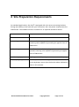
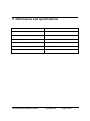
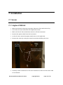
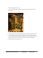
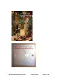
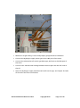
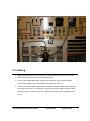
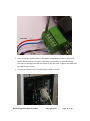
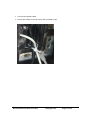
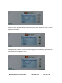
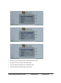
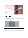
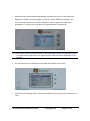
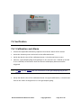
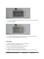
Installation Manual DVLS3 Simply, Smart Sensor Date: 12/10/2013 Table of Contents 1 ABOUT DA VINCI LABORATORY SOLUTIONS .............................................................................. 3 2 DVLS3 SIMPLY, SMART SENSOR SCOPE ......................................................................................... 4 3 SAFETY INFORMATION ..................................................................................................................... 5 4 SITE PREPARATION REQUIREMENTS .............................................................................................. 6 5 DIMENSIONS AND SPECIFICATIONS ............................................................................................... 7 6 PRINCIPLE OF OPERATION ................................................................................................................ 8 7 6.1 GENERAL ......................................................................................................................................... 8 6.2 HARDWARE DESCRIPTION ................................................................................................................ 9 INSTALLATION................................................................................................................................... 10 7.1 SENSOR ......................................................................................................................................... 10 7.2 CARRIER GAS VALVE ...................................................................................................................... 13 7.3 CABLING ........................................................................................................................................ 15 7.4 CONTROLLER ................................................................................................................................. 18 7.5 CALIBRATION ................................................................................................................................. 23 7.6 VERIFICATION ................................................................................................................................ 28 8 PARTS REPLACEMENT LIST ............................................................................................................. 32 9 DECLARATION OF CONFORMITY .................................................................................................. 33 DVLS3 Installation Manual 3.0.docx Copyright 2013 Page 2 of 33 1 About Da Vinci Laboratory Solutions As a versatile partner for analytical applications and authorized distributor of worldleading instrument manufacturers Da Vinci Laboratory Solutions (DVLS) is able to provide an expert advice and offers an extensive range of chromatographic systems, software, services and supplies. For information visit: www.davinci-ls.com or contact us at: Da Vinci Laboratory Solutions Cairostraat 10 3047 BC Rotterdam, The Netherlands Postbus 12103 3004 GC Rotterdam, The Netherlands T: +31-(0)10 258 1870 F: +31-(0)10 258 1879 E: [email protected] Note: In no event will Da Vinci Laboratory Solutions be liable for any loss or damage including incidental, indirect, special or consequential damages arising from the use of the DVLS3 Simply, Smart Sensor. Note: Information, descriptions and specifications in this publication are subject to change without notice. DVLS3 Installation Manual 3.0.docx Copyright 2013 Page 3 of 33 2 DVLS3 Simply, Smart Sensor Scope The DVLS3 Simply, Smart Sensor, hereafter referred to as DVLS3, is a multiple-purpose device capable to support up to four sensors. The multi-sensor capability includes sensors for Hydrogen, Hydrogen leak detector, temperature, barometric pressure and level (liquid) weight. Detection of Hydrogen in chromatography instrumentation is one of the main DVLS3 applications. The content of this manual is focused on installation for Hydrogen safety detection in GC solutions. In case you would like to receive information concerning the use of the DVLS3 for other purposes, please contact your local Da Vinci representative. DVLS3 Installation Manual 3.0.docx Copyright 2013 Page 4 of 33 3 Safety information Hydrogen is a colorless, odorless, flammable gas. Hydrogen poses a serious fire hazard when it is accidentally released. Hydrogen poses a number of hazards to human safety, from potential detonations and fires when mixed with air to being asphyxiating in its pure, oxygen-free form. Hydrogen gas leaking into external air may spontaneously ignite. Moreover, hydrogen fire, while being extremely hot, is almost invisible, and thus can lead to accidental burns. Note: Only trained and authorized personnel are allowed to open the Controller covers. DVLS3 Installation Manual 3.0.docx Copyright 2013 Page 5 of 33 4 Site Preparation Requirements For standard applications, the DVLS3 is equipped with the correct mounting brackets, fittings and cabling to be used with your instrument. Gas- and power requirements are listed below. The GasMix™ dilution instrument is an optional calibration device. Item Requirement Power: AC 100-240V 50-60Hz 0.5A Gas testing mixture: Mixture of: 2% Hydrogen, balance Air, with a pressure reducing valve capable of generating an approx. flow of 300 ml/min. Calibration gas: Certified mixture of: 2% Hydrogen, balance Air, with a pressure reducing valve capable of generating an approx. flow of 300 ml/min. GasMix™ supply gases:* Hydrogen 99.995% purity, Instrument air 99.995% purity Gas Sampling Bag Volume ≥ 1 liter, with tubing (no silicon!) for connection to the Hydrogen sensor (see the Section about Calibration, later in this manual). *only applicable if the GasMix™ dilution unit is included. DVLS3 Installation Manual 3.0.docx Copyright 2013 Page 6 of 33 5 Dimensions and specifications Maximum altitude: 2000 m Operating humidity range: 20 to 90% Controller operating temperature range: 10 to 40 °C Calibrated range H2 sensor: 0 to 50% LEL (0 to 2% Hydrogen in Air) Sensor signal cable length: ≤3m Controller dimensions: L x W x H: 12.0 cm x 14.2 cm x 6.3 cm IP Class IP 40 DVLS3 Installation Manual 3.0.docx Copyright 2013 Page 7 of 33 6 Principle of Operation 6.1 General An increasing number of laboratories decides to reduce costs and improve quality of a GC analysis by switching from the more expensive Helium carrier gas to the significantly lower priced Hydrogen gas. Hydrogen is, however, an explosive gas at a level of 4.1% in the air. This level is also known as 100% LEL (Lowest Explosion Limit). Da Vinci developed a Hydrogen sensor suitable for use with the DVLS3 unit. The DVLS3 constantly monitors the Hydrogen level in the GC oven. As soon as the Hydrogen concentration reaches the user defined level, typically between 25% and 50% LEL (equal to 1% - 2% by Vol Hydrogen), the alarm is triggered which will execute: An acoustic alarm A visible alarm on the LCD display of the controller Optional: an SMS alarm text message A valve switch to direct a safe carrier gas to the instrument A not-ready signal to the GC to stop the instrument sequence At any time, it is possible to switch off the acoustic alarm. Both the display, valve and not-ready alarm status will remain until the Hydrogen concentration has dropped to an acceptable level. Both the alarm level and safe level are adjustable. DVLS3 Installation Manual 3.0.docx Copyright 2013 Page 8 of 33 6.2 Hardware description The DVLS3 consists of three main items: Sensor assembly including GC mounting plate Valve assembly including GC mounting plate Controller Both the valve and sensor assembly are mounted on the GC, the position depends on the type of GC used. The controller box is normally placed on top of the GC, but may be installed in the near area as well. A hardcopy of the user manual is included as well. DVLS3 Installation Manual 3.0.docx Copyright 2013 Page 9 of 33 7 Installation 7.1 Sensor 7.1.1 Agilent 7890 GC Wear an antistatic wrist strap to protect electronics from static electricity. Cool down the oven and other GC temperature zones. Wait until the GC has cooled down and turn off the instrument. Remove the power cable from the instrument. In the GC oven, locate the square metal cover on the right side. Remove the cover by cutting the metal connections holding the cover. Carefully create a small hole in the oven insulation to allow for the sensor tube to be inserted. DVLS3 Installation Manual 3.0.docx Copyright 2013 Page 10 of 33 Remove the right side GC cover. Locate the detector boards, and the 2 mounting screws in between. Remove both screws. Protect the sensor tube from dust by capping the end with a plastic cap or tape. Insert carefully the sensor assembly through the side of the GC (please ensure not to damage the electronic boards or cabling), until the end of the sensor tube appears in the GC oven. Remove the tube protection cap/tape afterwards. Install the bracket using the top screw. DVLS3 Installation Manual 3.0.docx Copyright 2013 Page 11 of 33 DVLS3 Installation Manual 3.0.docx Copyright 2013 Page 12 of 33 7.2 Carrier gas valve Cool down the GC oven and wait until the temperature has dropped to ambient level. Turn off column pressure(s) and close the carrier gas supply. Mount the valve bracket on the rear side of the GC, using the mounting screws supplied. The bracket has pre-drilled holes which will fit on the back cover of a 6890, 7890 or 6850 GC. However it is possible that on different GC models the cover holes do not match with the bracket holes, or the positions are used by other devices such as Swagelok t-pieces. In these circumstances, drilling of additional holes in one of the GC covers is an option, installation of the valve on a laboratory wall or bench is another. DVLS3 Installation Manual 3.0.docx Copyright 2013 Page 13 of 33 Make sure all gas tubing is clean and properly purged before installation. Connect the Hydrogen supply carrier gas to the 1NC port of the valve. Connect the alternative safe carrier gas (Nitrogen, Helium) to the 3NO port of the valve. Connect 1/8” stainless steel tubing between the 2CO port and the EPC inlet of the GC. Open the Hydrogen supply and alternative safe carrier gas, and inspect for leaks at the valve and inlet connections. DVLS3 Installation Manual 3.0.docx Copyright 2013 Page 14 of 33 7.3 Cabling Place the controller on top of the GC, or alternatively next to the instrument. Install the green connector on the sensor board. Connect the LAN signal cable to the black connector on the sensor board. Connect the other end of the cable to the controller port 1-4. Connect the valve cable to the green connector as shown. Note: Depending on the type of GC used it is necessary to insert the cable through an existing hole near the sensor in the GC cover first. Tighten the cable pins by adjusting the screw. DVLS3 Installation Manual 3.0.docx Copyright 2013 Page 15 of 33 Connect the GC remote cable to the green connecter as shown in the picture below. Depending on the type of GC used it is necessary to insert the cable through an existing hole near the sensor in the GC cover. Tighten the cable pins by adjusting the screw. Connect the other end of the GC remote cable to the GC. DVLS3 Installation Manual 3.0.docx Copyright 2013 Page 16 of 33 Connect the power cable. Secure the cables to the GC using the enclosed ty rap. DVLS3 Installation Manual 3.0.docx Copyright 2013 Page 17 of 33 7.4 Controller Place the controller on top of the GC, or alternatively next to the instrument. 7.4.1 Main controller screens The controller exists of 2 main screens: The Summary view The Settings view By default, the Settings view is protected with a pin code (factory set at 1000). After connection of the Power cable, the Controller will shortly warm up. After a few seconds, the Summary view of the 4 sensors is displayed: Submenus are accessed by using the arrows next to the display. When an individual sensor is accessed, the following screen becomes available: DVLS3 Installation Manual 3.0.docx Copyright 2013 Page 18 of 33 The Raw data figure corresponds to the actual signal from the sensor. The Result value is a relative measure of the actual Hydrogen level. Between parentheses the default alarm level is shown. By further selecting the arrow buttons, the controller general status view is accessed: The first row shows the fixed or DHCP IP address, if the optional LAN communication is used. DVLS3 Installation Manual 3.0.docx Copyright 2013 Page 19 of 33 7.4.2 Settings menu and pin code protection All configuration parameters are available under the Settings menu. To access the Settings menu, hold the OK button while the display shows the Summary view. This will trigger a pin code authorization: After entering the default factory set pin code (1000), the Settings menu becomes available: To return to the Summary menu, hold the OK button. Note:It is strongly recommended to lock the Settings menu before returning to the Summary menu, otherwise calibration settings may be changed, as described in the following chapters. DVLS3 Installation Manual 3.0.docx Copyright 2013 Page 20 of 33 To return to the main Settings view from any Settings submenu, hold the OK button as well. 7.4.3 Initial setup After power up: it is recommended to verify or change the following configuration parameters: Pin code: The default pin code is 1000, and may be changed from the Settings view. Select Pin code and press OK to enter your own pin code number. Menu timeout: The default time the menu remains in the sensor trend menu. During calibration, it is recommended to temporarily increase the timeout value to 1000. DVLS3 Installation Manual 3.0.docx Copyright 2013 Page 21 of 33 Ethernet: if the optional LAN data communication is to be used, enter DHCP or fixed IP address requirements. Ethlog Intr: The frequency of real-time data logging (in microseconds) applicable if the data communication option is used. DVLS3 Installation Manual 3.0.docx Copyright 2013 Page 22 of 33 7.5 Calibration Each sensor can individually be calibrated at 2 levels: Zero level Cal level Calibration at Zero level results in an Offset value stored in the device. The Zero level is calibrated using air. Calibration at Cal level results in a multiply value stored in the device. The Cal level is calibrated using a 2% Hydrogen in air mixture, which corresponds to 50% LEL. Note:It is important that the correct Cal level is entered in the settings menu for the individual senor. The Cal level should be equal to the %LEL of the gas used for calibration. Both the Offset and Multiply values are stored per individual sensor. Between Zero level and Cal level 50% LEL the sensor response is linear. Sensors that are purchased with a controller, are factory calibrated with that specific controller. Note:The Offset and Multiply values on the accompanying Test Checklist apply to the factory calibration of the sensor with the specified serial number connected to the specified controller channel. If a sensor is connected to another channel than specified on the Test Checklist, the Offset and Multiply values on the Test Checklist do not apply. Recalibration is required. Calibration can be repeated at the time of installation of the Hydrogen sensor, and may be repeated once a year, or according to internal laboratory policies. Additional calibrations may also be carried out in case of signal drift, or after power outages. If a certified calibration gas is not available, it can be considered to only verify the calibration and alarm using either a 1% or 2% Hydrogen in air mixture following the verification procedure. DVLS3 Installation Manual 3.0.docx Copyright 2013 Page 23 of 33 Zero Level calibration: Ensure no Hydrogen is present near the sensor. To be certain, shut off the GC oven fan and GC Hydrogen supply modules. From the Summary view of the controller, hold the OK button and enter the pin code to unlock the Settings menu. Return from the Settings view to the Summary view by holding the OK button. Scroll down to the sensor to be calibrated. Observe the Raw signal for stability. Click the OK button shortly (do not hold). By shortly clicking OK, the sensor will be calibrated for the zero level Hydrogen. Note:Clicking the OK button in protected mode will not have impact on the calibration. Note:The Result value should read a number close to 0 after the Zero Level has been calibrated. Cal Level calibration: From the Summary view of the controller, hold the OK button and enter the pin code (this step can be skipped if the menu is still in unprotected mode). After entering the Settings menu, select the active sensor(s) and change the Alarm level temporarily to a level higher than the default alarm level of 25% LEL, to prevent an unwanted alarm during calibration: DVLS3 Installation Manual 3.0.docx Copyright 2013 Page 24 of 33 Return to the Summary view by holding the OK button. Scroll down to the sensor to be calibrated. Fill a gas sampling bag with the calibration gas. Connect the gas sampling bag to the sensor. DVLS3 Installation Manual 3.0.docx Copyright 2013 Page 25 of 33 Note:Do not use any silicon hose for connection of the gas sampling bag to the sensor! Wait for signal stabilization and then hold the OK button. By holding the OK button the calibration at Cal level is executed. Note:Holding the OK button in protected mode will not have impact on the calibration. Note:After Cal Level calibration, the Result value should read a number close to 50. DVLS3 Installation Manual 3.0.docx Copyright 2013 Page 26 of 33 Record the new stored Offset and Multiply (calibration) values in the instrument logbook or quality control program. In case of a major difference between the current and the previous or factory calibration values, repeat the calibration procedure, or contact your local Da Vinci representative for assistance. Note:Due to the nature and electronics of the Hydrogen sensor, the Multiply factor normally reads negative (a raw signal drop is observed when Hydrogen is detected). Set the Alarm for the calibrated sensor back the default value of 25. From the main Settings menu, protect the calibration by setting the Lock function to “On”. DVLS3 Installation Manual 3.0.docx Copyright 2013 Page 27 of 33 7.6 Verification 7.6.1 Calibration and Alarm Inform the responsible laboratory supervisor that sensor alarm will be tested. Access the Summary menu and scroll to the calibrated sensor. Verify the Result value of the calibrated sensor; it should read close to zero. Connect a gas sampling bag with Hydrogen in air (1% H2 in air = 25%LEL or 2% H2 in air = 50%LEL) to the sensor. Both the acoustic and display alarms should be triggered. Note: Do not use any silicon hose for connection of the gas sampling bag to the sensor! Verify the Result value of the calibrated sensor. At signal stabilization, it should read close to the %LEL of the gas that is in the gas sampling bag. DVLS3 Installation Manual 3.0.docx Copyright 2013 Page 28 of 33 Turn off the acoustic alarm by clicking the OK button. Now the Summary display will read “SILENT ALARM”. Disconnect the calibration gas. Wait for the signal to drop at the Alarm Off level, and verify the Summary display returns to <OK> state. 7.6.2 Valve Make sure the DVLS3 is calibrated and not in (silent) alarm. Shut off the supply of Hydrogen carrier gas. Disconnect the Hydrogen carrier gas from the 1NC port Disconnect the Carrier Out line from port 2CO. Make sure the supply of Safe carrier gas is opened. Connect a flow meter to the 2CO port and measure the flow. There should be no flow. DVLS3 Installation Manual 3.0.docx Copyright 2013 Page 29 of 33 Connect the gas sampling bag with the 2% H2 calibration gas to the Sensor. When the DVLS3 goes in alarm, turn of the acoustic alarm by clicking the OK button. Now the Summary display will read “SILENT ALARM”. Measure the flow from port 2CO. Now there must be flow (of safe carrier) coming out of this port. Disconnect the gas sampling bag from the Sensor. Check if the flow from port 2CO stops when the actual %LEL reaches the Alarm Off level (set to 20 %LEL during set up of the Controller). Close the Safe carrier gas supply and disconnect it from port 3NO. Connect the Safe carrier gas line to port 1NC and open the supply of Safe carrier gas. Make sure the DVLS3 is not in (silent) alarm. Measure the flow from port 2CO. There must be flow coming out of this port. Connect the gas sampling bag with the 2% H2 calibration gas to the Sensor. When the DVLS3 goes in alarm, turn of the acoustic alarm by clicking the OK button. Now the Summary display will read “SILENT ALARM”. Check if the flow from port 2CO stops when the actual %LEL reaches the Alarm On level (set to 25 %LEL during set up of the Controller). Disconnect the gas sampling bag from the Sensor. Check if there is flow again from the Carrier Out when the actual %LEL reaches the Alarm Off level. Close the Safe carrier gas supply. Disconnect the Safe carrier from port 1NC and reconnect it to port 3NO. Reconnect the Hydrogen gas supply to port 1NC. Reconnect the Carrier Out line to port 2CO. Open the Hydrogen carrier supply and the Safe carrier gas supply and verify that all connections on the valve and GC inlet are leak free using an appropriate leak detector. DVLS3 Installation Manual 3.0.docx Copyright 2013 Page 30 of 33 7.6.3 Connection Loss Alarm & Remote Make sure the DVLS3 is not in (silent) alarm. Make sure the GC is in Ready state (do not start an alaysis). Label each sensor cable with the number of the connector of the controller to which it is connected. Disconnect all sensor cables from the Controller. Now the DVLS3 should go into alarm and the Summary display should read “NO SENSORS” and the valve should switch from Hydrogen gas to Safe carrier gas. Reconnect each sensor cable to the same connector on the controller as to which it was connected during calibration. Note:The calibration applies to 1 specific sensor connected to 1 specific channel. After the test each sensor cable should be reconnected to the same connector on the Controller as to which it was connected during calibration. If the cable is connected to a different connector, the calibration is not valid anymore. The sensor should be regarded uncalibrated. Check if the GC goes to the Not Ready state. The Summary Display will read “OLD ALARM” Press the OK button to switch off the alarm. This will cause the valve to switch back from Safe carrier gas to Hydrogen carrier gas. The DVLS3 is now ready for use. DVLS3 Installation Manual 3.0.docx Copyright 2013 Page 31 of 33 8 Parts replacement list Da Vinci Product code Description DM-S3-78-H2-11 DVLS3 Hydrogen sensor for Agilent 7890GC complete DM-S3-68-H2-11 DVLS3 Hydrogen sensor for Agilent 6890GC complete DM-S3-XX-CO-10 DVLS3 Multisensor controller complete DM-S3-X8-VK-10 DVLS3 Valve kit for H2 sensor for Agilent 7890GC or 6890GC DVE-094401 Control gas 2% Hydrogen in Air 17 liter (for verification only) DVE-094402 Regulator for Control gas, including flow adapter. DVE-094407 Calibration gas: Air balance, Hydrogen 2% (50% LEL) 5 liter H2 steel cylinder, including brass valve adjustable flow (DVE094408). DVE-094408 Regulator Single-Stage General Purpose, Adjustable Flow Model for Calibration gas DVE-094408. DVLS3 Installation Manual 3.0.docx Copyright 2013 Page 32 of 33 9 Declaration of Conformity DVLS3 Installation Manual 3.0.docx Copyright 2013 Page 33 of 33