1
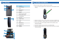
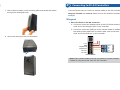
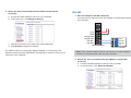
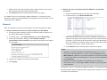
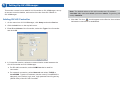
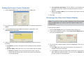
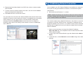
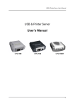
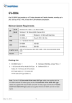
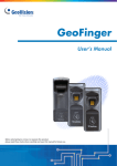
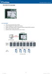
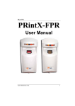
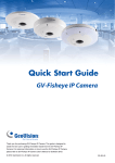
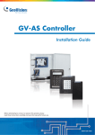
1
Introduction
Welcome to the GV-Camera Reader Quick Start Guide. The quick start
guide covers the basic installations and configurations of GV-Camera
Reader. For the detailed user’s manual, see the GV-Camera Reader
User’s Manual on the supplied software DVD.
Quick Start Guide
Packing List
● GV-CR420 x 1
● Mounting Plate x 1
● Standard Screw x 2
● Plastic Screw Anchor x 2
● Security Screw x 1
● Torx Wrench x 1
GV-Camera Reader
GV-CR420
● DC 12V Power Adapter x 1
● GV-Camera Reader Quick Start Guide x 1
● Software DVD x 1
Thank you for purchasing GV-Camera Reader. This guide is designed to assist
new users in getting started on the GV-Camera Reader. For detailed information
on how to use the GV-Camera Reader, please refer to GV-Camera Reader User’s
Manual on the supplied software DVD.
© 2013 GeoVision Inc. All rights reserved.
2013/02
English
CR420V101-QG-A
Compatible GV-AS Controller Versions
●
Limitations and Optimal Installation for Face Detection
GV-AS100 / 110 / 120 / ASBox / ASNet: Firmware version 1.05 or
later
Camera Reader Installation Height:
●
Building gate: about 1.4-1.5 meters above the ground.
●
GV-AS210: Firmware version 1.1.0 or later
●
Parking lot gate: about 1.2 meters above the ground.
●
GV-AS400: Firmware version 1.04 or later
●
GV-AS810: Firmware version 1.1.0 or later
P
Note: Card and Face Mode by schedule and receiving card numbers
through network connection are only supported in the following
firmware versions.
140cm
~
150cm
120cm
●
GV-AS100 / 110 / 120 / ASBox / ASNet: Firmware version 1.06 or
later
●
GV-AS210: Firmware version 1.1.0 or later
Face Detection Limitations
●
GV-AS400: Firmware version 1.04 or later
●
Cardholders cannot be wearing facial masks or sunglasses.
●
GV-AS810: Firmware version 1.1.0 or later
●
Detects front-view faces only. The tilt angle cannot exceed 15° degree.
Optional Accessories
Front
View Only
● GV-AS ID Card (13.56MHz, Mifare)
● GV-AS ID Tag (13.56MHz, Mifare)
±15° Horizontal
±15° Vertical
°+15°
-15
Lighting Conditions
●
Lighting should be sufficient with minimum illumination no less than
41-50 Lux.
●
Avoid having light source directly behind the subject.
2
3
Overview
No.
1
2
3
5
4
6
7
8
9
16
15
10
14
13
12
11
Function
Hardware Installation
Follow the steps below to install the camera reader.
1. Place the mounting plate on the wall with the oval-shaped hole toward
the top.
1
LED Indicator
2
Lens
3
Microphone
4
Speaker
5
Beeper
6
Network status LED
7
Ready status LED
8
Load Default
9
Ethernet
10
Power Cable
11
+12V
2. Mark the location of the 2 holes and the rectangle as labeled above.
12
GND
3. Drill the rectangle to create a space for running the cables and wires.
13
Wiegand D1
14
Wiegand D0
4. At the 2 dots, drill a hole slightly smaller than the plastic screw
anchors provided.
15
RS485-
16
RS485+
5. Insert the 2 plastic screw anchors in the drilled holes.
6. Place the mounting plate on the wall and secure with the 2 standard
screws provided.
4
7. Place camera reader on the mounting plate and thread the cables
through the rectangular hole.
Connecting to GV-AS Controllers
There are three ways to connect a camera reader to GV-AS Controllers:
Wiegand, RS-485 and network. Below we use GV-AS400 Controller as an
example.
Wiegand
1. Wire GV-CR420 to GV-AS Controller
a. Connect a wire to the Wiegand pins of the GV-CR420 and the
other end to the Wiegand pins on the controller.
b. Connect a wire to the GND pin of the camera reader in addition to
the existing black GND wire for power cable, and connect the
other end to the GND pin on the controller.
+12 V
GND
Wiegand D0
Wiegand D1
RS 485 RS 485+
GND
D0
D1
12V
Wiegand A
8. Secure the security screw on the bottom.
GV-AS Controller
Camera Reader
Note: Each camera reader must be connected to a power adapter
instead of using the power from GV-AS Controller.
2. Define the door associated with GV-CR420 on the GV-AS
Controller
a. Access the Web interface of the GV-AS Controller.
b. In the left menu, click Wiegand Setting.
c. Use the drop-down list to select the associated door.
d. Click Submit to apply the settings.
For details, refer to Connecting a Wigand Reader or Connecting Card
Readers section and the Web-Based Configurations section in the GV-AS
Controller User’s Manual.
RS-485
1. Wire GV-CR420 to GV-AS Controller
Connect the RS-485 pins of the GV-CR420 to the RS-485 interface on
the controller.
+12 V
GND
Wiegand D0
Wiegand D1
RS 485 RS 485+
Camera Reader
GND
RS 485RS 485+
12V
GV-AS Controller
Note: Each camera reader must be connected to a power adapter
instead of using the power from GV-AS Controller.
2. Define the door associated with GV-CR420 on the GV-AS
Controller
a. Access the Web interface of the GV-AS Controller.
b. In the left menu, click Extended Reader.
c. Select an ID, type the barcode of the camera reader, and use the
drop-down list to select the associated door.
d. Click Submit and the Setting Status should turn green.
For details, refer to Connecting a Wigand Reader or Connecting Card
Readers section and the Web-Based Configurations section in the GV-AS
Controller User’s Manual.
2. Define the door associated with GV-CR420 on the GV-AS
Controller
a. Access the Web interface of the GV-AS Controller.
b. In the left menu, click Extended Reader.
Network
Each GV-CR420 can only be connected to one AS Controller at a time.
1. Enable network connection to AS Controller on GV-CR420
a. Access the Web interface of the GV-CR420. Refer to section 6 in
the Quick Start Guide for details.
b. In the left menu, click Video Settings and select Streaming 1.
c. Under Face Detection Setting, select Enable network
connection to AS Controller and use the drop-down list to select
the controller.
c. Select an ID, type the barcode / MAC Address of the camera
reader according to the firmware version of GV-CR420 and the
controller, and use the drop-down list to select the associated
door. For details on firmware version and corresponding methods
of network connection, see the note below.
d. Click Submit and the Setting Status should turn green.
Note:
d. Type the IP address of the GV-AS Controller.
e. Click Apply.
1. Network connection between GV-CR420 firmware V1.0.1 and
GV-AS210 / 810 firmware V1.1.0 can only be established using
MAC address. Network connection between GV-CR420 firmware
V1.0 and GV-AS210 / 810 firmware V1.0 can only be established
using barcode.
2. Network connection between GV-CR420 and GV-AS400 or
GV-AS100 / 110 / 120 through ASBox / ASNet is only supported
using barcode.
For details, refer to Connecting a Wigand Reader or Connecting Card
Readers section and the Web-Based Configurations section in the GV-AS
Controller User’s Manual.
5
Setting Up GV-ASManager
This section covers how to add GV-AS Controller to GV-ASManager, set up
an access control schedule, and receive live view from GV-CR420 on
GV-ASManager.
Adding GV-AS Controller
1. On the menu bar of GV-ASManager, click Setup and select Device.
2. Click the Add icon on the top left corner.
3. Enter ID and Name of the Controller, select the Type of the Controller
and click OK.
4. In Connection section, select the communication mode between the
GV-AS Controller and GV-ASManager.
● For RS-485 connection, select COM Port that is used for
connection.
● For network connection, select Network and select TCP/IP or
LocalDDNS. Type the IP address, device name (if LocalDDNS is
selected), port number, login user, login password and Crypto key
(3DES code) of the GV-AS Controller.
Note: The default values of GV-AS Controller are: IP address
192.168.0.100; username admin; password admin; Crypto key (3DES
code) 12345678.
5. Click OK. The icon
should appear on the Device View window to
indicate the connection is established.
Setting Up Access Control Schedule
1. Click the Door/Gate tab in the Controller Setup dialog box.
● Card and PIN Code Mode: For GV-CR420, a card needs to be
presented and a face needs to be detected before access is
granted.
● Card or Common Mode: For GV-CR420, this mode is the same
as the Card Mode.
5. Click OK.
Receiving Live View from Camera Reader
Note: To receive live view and take snapshots of the camera reader on
the GV-ASManager, you must connect the camera reader to the
network first.
2. In the General section, enable Set Door Info. The default password is
admin.
3. To apply different access modes according to a schedule, click
Authentication Schedule.
4. Select an access mode on the toolbar and drag the mouse over the
timelines.
● Card Mode: Access card required to be granted access. (default
mode)
● Release Mode: Keep the door in an unlock status with the reader.
● Release by Card: The door will unlock only after a card is
presented and will remain unlocked during the time specified
for Release Mode.
Follow the steps below:
1. Click the Door/Gate tab in the Controller Setup dialog box.
2. In the Camera Mapping section, select Set Camera Mapping and
click the first Arrow button.
3. To connect the camera reader to the GV-ASManager, use one of
these ways:
● Click Add, select the type of the IP device, and enter its IP
address and login information.
● Click Search to detect all GeoVision IP devices on the same LAN.
After adding the camera reader, you must click the Modify button
to enter its login ID and password.
6
4. Expand the Host folder listed in the DVR List, select a camera reader
and click OK.
5. To map a second camera reader to the door, click the second Arrow
button and repeat the steps above
Establishing Network Connection
Once installed, your GV-Camera Reader is accessible on a network. Make
sure your PC has good network connection, and meet this system
requirement:
●
Microsoft Internet Explorer 7.x or later
6. Click OK and return to the main screen.
You can watch live view from the Camera Reader and monitor the access
activities of the door at the same time. When a compatible but not enrolled
card is swiped, you can right-click the “Access Denied: Invalid Card”
message and select New/Edit Card to enroll the card. For details on
enrolling cards, refer to the Setting Cards section in the GV-ASManager
User’s Manual.
Note: Additional settings are required for Microsoft Internet Explorer 8.0
or later. Please refer to Settings for Internet Explorer 8, Appendix A,
GV- Camera Reader User Manual.
The camera reader has a default IP address of 192.168.0.10, but when it
connects to LAN with a DHCP server, a dynamic IP address will be
assigned instead of 192.168.0.10. If no DHCP server exists, the default IP
address will be applied and you can follow the steps below to assign a
static IP address.
1. Open your web browser, and type the default IP address:
http://192.168.0.10. The computer must be under the same network
as the camera reader.
2. In both Login and Password fields, type the default value admin. Click
Apply.
3. In the left menu, select Network and then LAN to begin the network
settings.
7
The Web Interface
4. Select Static IP address. Type IP Address, Subnet Mask,
Router/Gateway and Primary DNS.
8
9
5. Click Apply.
6. To allow updating of images in Microsoft Internet Explorer, you must
set your browser to allow ActiveX Controls and perform a one-time
installation of GeoVision’s ActiveX component onto your computer.
IMPORTANT:
● If Dynamic IP Address or PPPoE is enabled, you need to know
which IP address the camera reader will get from the DHCP server
or ISP to log in. If the camera reader is installed in a LAN, use the
GV-IP Device Utility to look up its current dynamic IP address. See
Checking the Dynamic IP Address, Chapter 3, GV-Camera Reader
User’s Manual.
If the camera reader uses a public dynamic IP address via PPPoE,
use the Dynamic DNS service to obtain a domain name linked to the
camera reader’s changing IP address first. For dynamic DNS server
settings, see Advanced TCP/IP, Chapter 5, GV-Camera Reader
User’s Manual.
● If Dynamic IP Address or PPPoE is enabled and you cannot
access the camera reader, you may have to reset it to factory
default settings and perform the network settings again. Refer to
section 9 in the Quick Start Guide to see how to restore to factory
default settings.
1
2
3
4
5
No.
1
2
3
Name
Play
Stop
Microphone
4
5
6
7
Speaker
Snapshot
File Save
Full Screen
8
Show System
Menu
9
Control Panel
6
7
Function
Plays live video.
Stops playing video.
Talks to the surveillance area from the local
computer.
Listens to the audio around the camera.
Takes a snapshot of live video.
Records live video to the local computer.
Switches to full screen view. Right-click the image
to have these options: Snapshot, Resolution,
PIP, PAP, GPS and Google Maps.
Brings up these functions: Alarm Notify, Video
and Audio Configuration, Remote Config,
Show Camera Name and Image Enhance.
Shows camera information, video settings, audio
data rate, images captured upon motion and GPS
location of the camera reader. Also allows you to
adjust image quality and install programs from the
hard drive.
8
Upgrading System Firmware
GeoVision periodically releases updated firmware on the website. Follow
the steps below to load the new firmware into the camera reader.
IMPORTANT:
● While the firmware is being updated, the power supply and network
connection must not be interrupted.
● Before upgrading firmware, stop connection to GV-System, Center
V2, VSM and RTSP.
1. In the Live View window, click the Show System Menu button
on the right and select Remote Config.
2. Click the Browse button to locate the firmware file (.img) saved at your
local computer.
3. Click the Upgrade button to process the upgrade.
WARNING: The interruption of power supply during updating causes
not only update failures but also damages to your camera. In this case,
please contact your sales representative and send your device back to
GeoVision for repair.
9
Restoring to Factory Default Settings
You can restore the camera reader to factory default settings using the
Web interface or directly on the camera reader.
Using the Web Interface
1. In the left menu, select Management and select Tools.
2. Under the System Settings section, click the Load Default button.
Directly on the Camera Reader:
1. Unplug the power cable.
2. Use a pointy object such as the tip of a pen to hold down the Load
default button while plugging the power cable.
Load default
3. Wait until the ready LED blinks twice to release the Load default
button. The process takes about 35 seconds.
Ready LED
9F, No. 246, Sec. 1, Neihu Rd., Neihu District, Taipei, Taiwan
Tel: +886-2-8797-8376 Fax: +886-2-8797-8335
[email protected]
http://www.geovision.com.tw