1
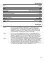
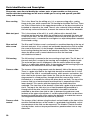
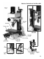
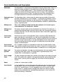
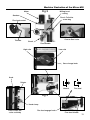
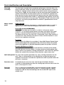
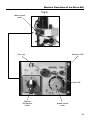
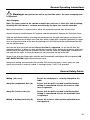
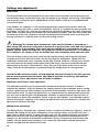
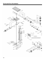
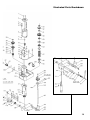
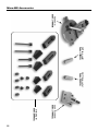
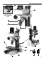
Code 505098
SX1 Super
Micro-Mill MKII
Index of Contents
Page No
Index of Contents
02
Declaration of Conformity
What’s in the Included
General Instructions for 230V Machines
Initial Assembly and Testing
Specification
Definitions
Parts Identification and Description
Machine Illustration of the Micro-Mill
General Operating Instructions
Settings and adjustments
Maintenance
Illustrated Parts Breakdown
Illustrated Parts List
Micro-Mill Accessories
Micro-Mill Oiling Points
02
03
04
05-06
07
07
08-10-12
09-11-13-14
15
16
17
18-19
20-21
22
23
Declaration of Conformity
The undersigned, Ole Stilling authorised by Shanghai SIEG Machinery Co., Ltd.
No.555 Caofeng Rd., South to No. 17 Bridge of Caoan Rd., Shanghai declares that this product:
(Micro Mill) SX1
manufactured by Shanghai SIEG Machinery Co. is in compliance with the following
standards or standardisation documents
EN55014-1:2000, EN55014-2:1997
EN61000-3-2:2000, EN61000-3-3:1995
in accordance with Council Directives
(89/336/EEC amended by 93/68/EEC)
symbols below advise that you follow the correct
Warning The
safety procedures when using this machine.
Fully read manual
and safety instructions
before use
02
Ear protection
should be worn
Eye protection
should be worn
HAZARD
Motor gets hot
What’s in the Included
Quantity
Item
1 No. Micro Mill with Chuck and Draw Bar fitted
Box containing:1 No.
3 No.
1 No.
1 No.
1 No.
1 No.
1 No.
4 No.
1 No.
1 No.
1 No.
1 No.
Model Number
SX1
Chuck Key
Rod Handles (detached for packing)
Double Open Ended Spanner 5mm A/F x 5.7mm A/F
Double Open Ended Spanner 8mm A/F x 10mm A/F
Nipple ‘C’ Spanner 28mm-32mm
Allen Key 3mm
Allen Key 6mm
‘T’ Slot Keepers
Tommy Bar
Oiling Bottle
Spare Fuse (250v x 1 Amp)
User Manual
!
Please read the Instruction Manual prior to using your new machine; as well as
the installation procedure, there are daily and periodic maintenance recommendations to
help you keep your machine on top line and prolong its life. Keep this Instruction Manual
readily accessible for any others who may also be required to use the machine.
Having unpacked you machine and its accessories, please check the contents against the
equipment list "What’s included", if there are any discrepancies, please contact Axminster
Tool Centre using the procedures laid down in the catalogue.
Please dispose of the packaging responsibly, much of the material is bio-degradable. The
machine and its accessories will arrive coated with heavy corrosion preventative grease. This
will need to be cleaned from the machine, its components and accessories prior to it being set
up and commissioned. Use coal oil, paraffin or a proprietary degreaser to remove the barrier
grease. Be warned, it will stain if you splash it on clothing etc., wear overalls, coverall et al.,
rubber gloves are also a good idea, as is eye protection if your cleaning process tends to be a
little bit enthusiastic. After cleaning, lightly coat the exposed metal surfaces of the machine with
a thin layer of light machine oil. N.B If you used paraffin/kerosene make sure you apply this thin
film sooner rather than later.
03
General Instructions for 230V Machines
Good Working Practices/Safety
The following suggestions will enable you to observe good working practices, keep yourself safe
and maintain your tools and equipment in good working order.
!
WARNING!! KEEP TOOLS AND EQUIPMENT OUT OF THE REACH OF YOUNG CHILDREN
Mains Powered Tools
Primary Precautions
These machines are supplied with a moulded 13 Amp. plug and 3 core power cable. Before using the
machine inspect the cable and the plug to make sure that neither are damaged. If any damage is visible
have the damaged item inspected/repaired by a suitably qualified person. If it is necessary to replace the
plug, it is preferable to use an ‘unbreakable’ type that will resist damage on site. Only use a 13 Amp plug,
and make sure the cable clamp is tightened securely. Fuse as required. If extension leads are to be used,
carry out the same safety checks on them, and ensure that they are correctly rated to safely supply the
current that is required for your machine.
Work Place/Environment
The machine is not designed for sub-aqua operation, do not use when or where it is liable to get wet. If the
machine is to be used outside and it starts to rain (unusual though this would be in U.K.), stop work and
move it inside. If machine has got wet; dry it off as soon as possible, with a cloth or paper towel. Do not use
230Va.c. powered machines anywhere within a site area that is flooded or puddled, and do not trail
extension cables across wet areas. Keep the machine clean; it will enable you to more easily see any
damage that may have occurred. Clean the machine with a damp soapy cloth if needs be, do not use any
solvents or cleaners, as these may cause damage to any plastic parts or to the electrical components.
Keep the work area as uncluttered as is practical, this includes personnel as well as material.
!
(Under no circumstances should CHILDREN be allowed in work areas)
It is good practice to leave the machine unplugged until work is about to commence, also make sure to
unplug the machine when it is not in use, or unattended. Always disconnect by pulling on the plug body and
not the cable. Once you are ready to commence work, remove any tools used in the setting operations
(if any) and place safely out of the way. Re- connect the machine.
Carry out a final check e.g. check the cutting tool, drill bit, saw blade etc., is securely tightened in the
machine, check you have the correct speed and function set, check that the power cable will not ‘snag’ etc.
Make sure you are comfortable before you start work, balanced, not reaching etc.
If the work you are carrying out is liable to generate flying grit, dust or chips, wear the appropriate safety
clothing, goggles, gloves, masks etc., If the work operation appears to be excessively noisy, wear
ear-defenders. If you wear your hair in a long style, wearing a cap, safety helmet, hairnet, even a
sweatband, will minimise the possibility of your hair being caught up in the rotating parts of the machine,
likewise, consideration should be given to the removal of rings and wristwatches, if these are liable to be a
‘snag’ hazard. Consideration should also be given to non-slip footwear, etc.
Do not work with cutting or boring tools of any description if you are tired, your attention is wandering or
you are being subjected to distraction. A deep cut, a lost fingertip or worse; is not worth it!
Do not use this machine within the designated safety areas of flammable liquid stores or in areas where
there may be volatile gases. There are very expensive, very specialised machines for working in these
areas, THIS IS NOT ONE OF THEM.
Check that cutters, drills, blades etc., are the correct type and size, are undamaged and are kept clean and
sharp, this will maintain their operating performance and lessen the loading on the machine.
Above all, OBSERVE…. make sure you know what is happening around you, and USE YOUR COMMON
SENSE.
04
Initial Assembly and Testing
Ideally, your mill should be installed close to a correctly rated power supply, in a
warm dry environment, well ventilated and illuminated by bright clear natural light,
with adequate access all around the machine, and sufficient adjacent storage space
for your tools, accessories and material.
The Micro-Mill is best mounted on a rigid bed; this is to ensure stability of the machine and to
attenuate any vibration that is generated when the machine is running.
The bed should be flat and set level in both planes, and at a height that enables comfortable
operation of the machine. It is not necessary to anchor the bed through to the floor, but it must
be stable enough to remain immovable during any normal forceful operations (especially
tightening) carried out whilst operating your mill.
If you are preparing your own bed for the machine, it should be at least 400mm long by 250mm
wide; (to cover the footprint of the base (354 x 216), you will need to drill 4 No. 8.5mm holes to
allow for bolt fixing. Set out the centres of the holes in the following matrix: 294mm x 186mm
Bolt the mill to the bed using M8 nuts, bolts and washers.
Locate and identify the 3 rod handles from the packing box. Fit these to the 3 wheel
handles, (Work table control, traverse feed control, head raise and lower control.)
!
Please read the section entitled Identification and Parts description so that
you may more easily identify the parts to which reference is made in the text.
Testing
When the lathe is mounted to your satisfaction, proceed as follows:a) Close the chuck jaws
b) Check the millhead is ‘locked’ in position on the column.
c) Check that all loose items are removed from the worktable.
d) Set the worktable approximately mid-positioned under the chuck jaws.
e) Check the speed control is switched OFF (fully anti-clockwise).
f) Check the Forward/Off/Reverse Switch is in the Off position
g) Select L (Low) on the gear box .
h) Connect the machine to the mains supply and switch power on.
i) Turn the Speed Control Switch On (Clicks On) and Select Forward on the Forward/Off/Reverse
switch.
J) Check the Amber LED (Fault Light) is illuminated and the green light is illuminated.
k) Switch the Speed Control Switch Off ( Clicks Off) and the Amber Led is now Off and the Green
light stays on.
05
Initial Assembly and Testing
l) Turn the Forward/Off/Reverse switch to Off position (Clicks Off) all lights are now off.
m) Select Forward on the Forward/Off/Reverse switch.
n) Turn the Speed Control Switch On and advance until the Chuck starts to rotate.
o) Turn the Forward/Off/Reverse switch to Off position, check that the machine stops, turn the
Forward/Off/Reverse switch to Forward, check that the Green light comes on and the Amber LED
comes on and the machine does not start. Turn all switches off ( All lights are off).
p)Turn Forward/Off/Reverse switch to Forward.
q) Turn the Speed Control Switch On (Clicks On), advance until the chuck starts to rotate.
r) Over a period of approximately 5 minutes advance the speed in stages to maximum, run at
maximum for at least 2 minutes, check that there is nothing untoward, (no excessive vibration,
speed progression is smooth etc.). Stop the spindle and change the gear selector to H (High),
carry out the previous check. Repeat the checks with the motor set in reverse.
s) If all the above checks are correct, stop the spindle, (turn the speed control to zero and select
Off on the direction selector switch. Ensure the fine feed control is disengaged, using the
‘coarse’ feed lever handle, exercise the quill up and down, check the movement is smooth and
precise.
t) Select the fine feed function, (if necessary ‘joggle’ the feed hand to enable the gears to mesh).
Raise and lower the quill using the fine feed control. Check the movement is smooth and precise,
there are no hard spots and the feed doesn’t bind up.
u) Exercise the worktable and the traverse feed, check you have full travel and that the
movements are smooth and ‘tight’. Reposition the worktable approximately mid-way and lock in
position, check that the table will not move when ‘reasonable’ force is applied to either the
traverse or longitudinal feed handles. (Note. Reasonable force is meant to indicate that force you
would apply to proceed with the next action, and that the resistance to the action would make
you investigate as to why the action was blocked. It is not meant as a challenge for you to bunch
muscles and heave).
v) Ensure the head lock clamp is loosened and exercise the rise and fall, driving the head up and
down the tool post. Check the movement is smooth and tight. Leave the head fairly well down
the tool post for the next check.
w) Loosen the tilt clamp bolts, and tilt the tool post to the left and right, clamp the tool post in an
arbitrary position and tighten the clamp bolts. Check that the tool post remains locked in place.
(WARNING. If the tool post is tilted too far out of the vertical the mill can become unstable if it is
not fastened to a solid workbench. Exercise care.) Return the tool post to the vertical.
x) If all the above checks are correct, your mill is now ready for use. Enjoy.
06
Specification
Code
505098
Model
SIEG SX1
Power
150W
Spindle Speed
Variable 100-1,000 & 100-2,000rpm
Spindle Taper
2MT
Nose of Spindle to Table (MAX)
Head Tilt
45˚ 0˚ 45˚R
Longitudinal Table Movement
Lateral Table Movement
Table Size
Overall L x W x H
Weight
255mm
180mm
90mm
240 x 145mm
430 x 355 x 715mm
32kg
Definitions
‘X’ Axis.
This is the axis described by the work table as it is moved side to side.
Normally, movement that moves the tool to the right in the workpiece is
referred to as +ve ‘X’, and movement that moves the tool to the left in the
workpiece is referred to as –ve ‘X’. Where the initial position of the tooling
and the worktable is designated 0,0. (Horizontal plane only).
‘Y’ Axis.
This is the axis described by the work table as it is moved from front to
back.(Traverse) Normally movement that moves the tool to the front in the
workpiece is referred to as-ve ‘Y’, and movement that moves the tool to the
rear in the workpiece is referred to as+ve ‘Y’. Where the initial position of
the tooling and the worktable is designated 0,0.(Horizontal plane only).
‘Z’ Axis
This is the axis described by the worktable in the vertical plane. (Not possible
with this machine). However, to establish a point in space, the co-ordinates
can be transferred to the ‘tip’ of the tooling, whereby, if we assume that the
tool and the worktable in their initial positions, where designated 0,0,0,
(Horizontal and vertical planes) any point above the tool tip is referred to as
+ve ‘Z’, and any point below the tool tip is referred to as -ve ‘Z’
07
Parts Identification and Description
Please take some time to identify the various parts of your machine so that you are
familiar with the terminology we will use to enable you to set up and operate your Mill
safely and correctly.
Base casting
This is the ‘Stand’ for the milling m/c. It is a square casting with a seating
flange to the rear, which mounts the Tilt Housing for the Main Tool Post. There
are 4 No. 8.75mm holes in the approximate corners of the base to enable it to
be bolted to a bench or the stand. There is also a dovetail slide machined on
the front top surface of the base, to mount the traverse slide of the worktable.
Main tool post
This is the column of the mill, it is an 65 x 50 bar with a dovetail slide
machined on the front onto which the milling head is mounted, the lower part
is the circular ‘boss’ for the tilt assembly. On the left side of the post a scale,
graduated in mm’s, is mounted to read against an adjustable pointer mounted
on the head casting.
Rise and fall
drive screw
The Rise and Fall drive screw is anchored in a machined housing at the top of
the main tool post. It has a wheel and rod handle keyed to the shaft to enable
the screw to be turned. It is fed through a threaded dog that is bolted to the
head casting allowing the head to be moved up and down. Viewed from
above the drive screw is turned clockwise to raise the head and
anti-clockwise to lower it.
Tilt housing
The tilt housing is mounted to the base casting using 4 bolts. The tilt ‘boss’ of
the main tool post is mated to the housing and clamped by a further 4 bolts.
The main tool post can tilt 45(degrees) from the vertical either left or right.
There is an adjustable pointer and a scale mounted on the housing to give an
indication of the amount of tilt that has been applied.
Traverse slide
The traverse slide casting mounts onto the dovetail slide of the base casting.
There is a gybe strip fitted to the right side dovetail to maintain the fit. In the
front face of the slide is a machined housing which mounts and anchors the
drive shaft for the traverse feed. Under the slide (on the base) is a threaded
dog mounted in a fixed position, through which the traverse drive shaft is
threaded so as to enable the slide to be driven back and forth. The top of the
traverse slide has a female dovetail machined into it, perpendicular to the
lower dovetail. This marries with the dovetail on the underside of the
worktable. The front face of the dovetail is fitted with a gybe strip to maintain
the fit. The top of the slide also has a fixed threaded dog mounted to it,
through which the drive shaft of the worktable is threaded to allow the
worktable to be driven from side to side. In between the grubscrews and
locknuts of the gybe strip adjustors is an M4 caphead bolt that can be driven
forward to clamp the gybe strips against the dovetails to enable the traverse
and longitudinal movements to be locked in position.
Traverse slide
control
The traverse slide is driven using the wheel and rod handle at the front of the
machine. Behind the boss of the handle is a graduated ring (thimble) so that
the movement of the slide can be measured. The thimble is held to the drive
shaft by friction, and can be pre-positioned to a predetermined start or stop
dimension.
08
Machine Illustration of the Micro-Mill
Fig 1
Main tool
post
Worktable
Traverse slide
Rise & fall
drive screw
Worktable
control
Base casting
Traverse
drive control
Worktable
gybe strip
adjustors
Tilt
scale
Typ. 4
bolts
Fig 2
Tilt housing
0-45˚ tilt
Rear View
09
Parts Identification and Description
Worktable
The Worktable is a machined casting 240mm long by 145mm wide. There is a
dovetail section machined in the underside to mate with the traverse slide.
There are 3 x 8mm open ended ‘T’ slots machined in the table along its
length, to facilitate the fixing of machine vices or clamps. The worktable is
mounted onto the traverse slide. The right end face of the worktable has a
housing machined in it to mount and anchor the drive shaft assembly.
Worktable drive
control
The Worktable slide is driven using the wheel and rod handle at the end of
the table. Behind the boss of the handle is a graduated ring (thimble) so that
the movement of the worktable can be measured. The thimble is held to the
drive shaft by friction, and can be pre-positioned to establish a predetermined
start or stop dimension.
Milling head
This is the ‘milling machine’ and the descriptions of its various parts
and components are detailed as follows:-
Milling head
casting
The main casting to which all the components are attached. The head has a
dovetail housing machined at the rear, which allows the casting to be fitted to
the Main Tool Post. The left side of the dovetail slide is fitted with a gybe strip
to maintain the fit.
Head clamp
and scale
Similar to the traverse and longitudinal slides, centrally located between the
gybe strip adjusters and locknuts is an M4 bristol handled bolt that clamps
the gybe strip against the slide to effect a locking action for the rise and fall of
the head. In the same location is an adjustable pointer which reads against
the scale mounted on the main tool post, to enable the head to be moved
against a reference point.
Rise and fall
An ‘L’ shaped casting that is threaded to accept the rise and fall drive screw,
drive screw dog and is driven along the thread when the screw is turned. As it is bolted to the
milling head, the head will therefore follow its movement as it is being driven.
Motor and
gearbox
The motor and gearbox assembly are mounted above the main head casting
at the top of the arbor sleeve. The motor drive is geared through to the
spindle with an intermediate 2:1 gearbox.
Gear change
knob
The gear change knob allows the selection of the high or low ratio of the gear
train. The speed of the spindle is then governed by the speed control on the
motor panel. (You may have to ‘joggle’ the chuck/tool to aid the meshing
action).
Motor
A 220V d.c. motor rated at 150W.
Feed Handle
Lever handle that is used to drive the quill (and hence the chuck or the tool)
up and down. The boss of the handle is fitted to the end of a ‘splined’ gear
shaft. This ‘splined’ gear is, in turn, engaged in the rack cut into the quill
body. There is a counter balance spring in the arbor and sleeve assembly,
giving a more controlled ‘feel’ during drilling operations. It also retracts the
quill when drilling is completed.
10
Machine Illustration of the Micro-Mill
Fig 3
Motor
Milling head
casting
Gearbox
Rise & Fall drive
screw dog
Fine feed control
Coarse feed scale
Thimble
Chuck
Feed handle
Low ratio
High ratio
Gear change knob
Scale
Pointer
Normal
Fine feed
Fig 4
Head clamp
Head clamp and
scale assembly
Fine feed engage knob
Fine feed thimble
11
Parts Identification and Description
Fine feed
assembly
The fine feed assembly floats around the splined gear shaft that drives the
quill up and down. When the action of the fine feed mechanism is required;
pulling out ‘engage’ knob of the fine feed control meshes the gearing (you
may have to ‘joggle’ the feed handle to aid the meshing action) between the
splined shaft and the fine feed control shaft; this enables the spindle to be
driven by the fine feed control wheel with greater precision. Behind the boss
of the fine feed control wheel handle is a graduated ring (thimble) so that the
movement of the quill can be measured. The thimble is held to the drive shaft
by friction, and can be pre-positioned to establish a predetermined start or
stop dimension.
Motor control
panel
Power On LED
Green LED that indicates that power is available to the motor. i.e. mains is
applied, fuse is intact and the Emergency stop switch is not activated.
Fault LED (marked UNNORMAL)
Amber LED that indicates that there is a fault or an incorrect control
sequence. i.e. the chuck guard interlock has been activated or the speed
control is activated without forward or reverse direction being selected.
The Motor will not run if the fault LED is illuminated. If the safety interlock is
activated, the safety interlock will remain in force until the interlock is reset
and the start sequence re-initiated.
Fuse Cap
Access cap for the 20mm fuse cartridge (1 Amp 250V) Speed Control Knob
Round raised ridge knob connected to the circuit that controls the spindle
speed (100-1000 rpm or 100-2000 depending upon the gearbox selection).
Forward /Off/Reverse Switch
Three position switch that controls the direction of rotation of the spindle.
Forward indicates that the spindle is turning clockwise (looking down from
above, reverse, the spindle is turning anticlockwise. The centre OFF position
inhibits the spindle from turning in either direction, under motor drive.
Quill hold pocket The size of the machine precludes any ‘fancy’ locking mechanism for the
quill. There is a blind pocket on the spindle that accepts the tommy bar
supplied in the tool kit, to enable the spindle to be held in position whilst the
draw bar is loosened.
Draw bar cover
A moulded plastic cover that clips into the top of the Motor Gearbox
assembly, to afford protection from the rotating top of the draw bar, when the
quill is at the top of its travel.
Draw bar
(unseen)
This is a metal rod, threaded M10 at one end and with an 8mm squared
shank and flange machined on the other. It is fitted through the spindle
mandrel to hold the fitted tool/tooling hard into the No2 MT taper of the
spindle shaft.
12
Machine Illustration of the Micro-Mill
Fig 5
Motor control
panel
Fuse cap
Power on LED
Fault LED
Forward
/Off/Reverse
switch
Speed control
knob
13
Machine Illustration of the Micro-Mill
Fig 6
Blind pocket
Fig 7
Draw bar cover
14
Spindle
Top of draw bar
General Operating Instructions
!
Warning Do not operate the mill in any function unless the head clamping lever
is tightened.
Tool Changing
Note. The taper socket in the spindle mandrel does not have a ‘drive flat’ and all tooling,
including the drill chuck is secured and driven by the taper lock and the draw bar.
Make sure the power is switched off or better still remove the power from the machine.
Locate and put to hand the 8mm A/F spanner and the tommy bar. Remove the Draw Bar Cover.
Hold the quill immoveable by inserting the tommy bar into the quill hold pocket and loosen the
draw bar. Unscrew two or three turns and then strike sharply with a hammer (preferably a copper
face, to prevent the head of the draw bar peining over) this will break the lock between the tool
and the spindle tapers .
Unscrew the draw bar from the tool. Ensure the tool is supported, i.e. will not fall onto the
workpiece/table et al. When it is free put the tool carefully aside, remove the draw bar, check the
thread, check the taper and the thread of the new tool are clean and undamaged, introduce the
new tool into the taper, re-insert the draw bar and screw into the top of the tool.
Screw in the draw bar finger tight. Hold the quill immoveable and tighten with the spanner. DO
NOT OVERTIGHTEN. Replace the draw bar cover.
Remove all tooling and reconnect the machine. Ensure the tool path is clear, switch on, and
check that the tool is correctly seated, is running true etc. If all is O.K, proceed.
General Safety Points
Milling (all cases)
Ensure the workpiece is securely clamped to the
table.
Along the longitudinal Axis (X)
Ensure that the quill is locked in position before
milling is commenced. Ensure the traverse slide
lock is tightened.
Along the Traverse Axis (Y)
Ensure that the quill is locked in position before
milling is commenced. Ensure the worktable lock
is tightened.
Milling or Drilling Vertically (Z)
Ensure the traverse slide and the worktable locks
are tightened.
15
Settings and adjustments
Feed scales
The three thimbles that are mounted on the feed shafts of the worktable, the traverse feed and
the fine feed control should move freely with the motion of the handles and not slip. The thimbles
can be turned, using more force, independently of the handle in order to set a predetermined
start or finish point.
If the thimbles are ‘slipping’ i.e. not maintaining their place relative to the handle, whilst the
handle is turning; the cause is almost inevitably dirt, swarf et al., between the pressure plate and
the thimble. To rectify this, undo the nut and washer securing the handle to the shaft, remove the
hand wheel, and then remove the keyed collar and thimble assembly. Take care that the key does
not drop out of the shaft. Gradually separate the thimble from the keyed collar, by twisting and
turning, until there is sufficient space to clean the mating surfaces.
!
Warning The friction drive between the collar and the thimble is effected by a
wire spring (like part of a circlip) that is housed in a groove in the collar and rubs against
the inside bore of the thimble. If the collar and the thimble are separated too far, the
groove and the spring are exposed. The spring can fall out and if not lost, it is awkward
to re-compress the spring so that the thimble will slide completely back onto the collar.
Once the mating surfaces are clean, mate the key and the keyway and fit the collar/thimble
assembly to the shaft. Refit the washer and the securing nut, and tighten. Tighten until the
handwheel, thimble and collar assembly are too tight to move. Undo the securing nut a quarter
turn and check that the drive handle rotates freely and there is not excessive backward and
forward play in the shaft. (The handle etc, forms one side of the drive screw anchor into the
slide). Check the thimble remains synchronized with the handle whilst it is being turned.
Your Micro-Mill has been factory set and adjusted, however, during its life time you may
find occasion whereby the mill needs adjusting to maintain its accuracy and optimum
performance. These adjustments can be made as follows:Worktable and Traverse feed adjustment
The worktable and the traverse feed are both mounted over dovetail sections. In order to
maintain the ‘tightness’ of the fit; between the sloping surface of the component and its mating
surface a gybe strip has been inserted. (At the front of the worktable, and to the right hand side
of the traverse feed). To adjust the gybe strips, use supplied allen key and spanner, release the
lock nuts and screw the gybe strip grubscrews clockwise to compensate for any slackness or
anti-clockwise to loosen the movement. Check, using the feed handles, that worktable and the
traverse feed moves smoothly, If not, repeat the adjustments until the movement is smooth and
tight over the whole of the travel.
Milling Head adjustment
The Milling Head is mounted over a dovetail section. In order to maintain the ‘tightness’ of the fit;
between the sloping surface of the component and its mating surface, on the left hand side, a
gybe strip has been inserted. To adjust the gybe strip, use the supplied allen key and spanner,
release the lock nuts and screw the gybe strip grubscrews clockwise to compensate for any
slackness or anti-clockwise to loosen the movement. Check, using the rise and fall drive feed
handles, that the head moves smoothly, If not, repeat the adjustments until the movement is
smooth and tight over the whole of the travel.
16
Maintenance
Your Mill is a precision tool. In order to maintain this precision and prolong its useful life,
it is advised that you follow the recommended daily and periodic maintenance tables
printed below.
Daily and Periodic Maintenance
Daily
Carry out a visual inspection. Repair any damage immediately. Minor damage to
the beds should be taken out with an oilstone.
Move the worktable and the traverse feed back and forth by hand, check that the
movement is smooth.
Spread a light film of oil over the worktable and the traverse slide bed.
Oil the end bearings of the drive shafts. Squirt oil onto the slide faces of mating
components.
Exercise the components to ensure the oil is spread over both visible and obscure
surfaces.
Daily after-use
1. Clean all swarf and chips away from the machine bed, slide surfaces,
and the tool post.
2. Exercise the slides and ensure no swarf etc., is lodged in the drive shaft tunnels.
If you have been using a coolant make sure the machine is thoroughly dried off.
3. Check the tool, ensure it is usable the next time, if not re-sharpen or replace
the tool tip.
4. Lightly oil spray all the machine beds and surfaces.
5. Clean and lightly oil any tools you may have been using (drill chucks, spanners,
chuck keys etc), and put them away.
6. Switch off the power supply. Disconnect the plug.
7. Cover the machine over with a dust cloth.
Weekly
1. Move the traverse slide fully back to give access to the tunnel, blow out to make sure
all swarf is cleared away and heavily spray oil the tunnel, exercise the slide to work the
oil into the drive thread and to lubricate the dog.
2. Spray oil the slide and the worktable bed, exercise the worktable to spread the oil
to all surfaces, both hidden and visible.
3. Spray oil the underside of the machine onto the drive screws, exercise to ensure the
oil is coating all components.
4. Clean and spray oil the rise and fall drive screw, exercise to ensure all parts are
coated.
5. Check the movement of the worktable, the traverse slide and the head, check they
are smooth and ‘tight’, if necessary reset the gybe strips until the movements are
smooth and tight.
6. Wipe the quill outer sleeve clean and lightly oil, exercise the quill to spread the
oil in the sleeve bushes.
Monthly
a) Give the motor a good ‘blow through’ to remove any dust, dirt etc,
b) Check all the interlocks function correctly.
Accessories
There are numerous accessories for the machine listed in the Axminster catalogue.
Some are illustrated at the rear of this manual.
17
Illustrated Parts Breakdown
18
Illustrated Parts Breakdown
19
Illustrated Parts List
20
Illustrated Parts LIst
PC Board Replacement Part No:
Part No: 600883
21
Micro-Mill Accessories
Vice 55mm
Code: (100034)
2MT 6mm collet
Code: (100023)
2MT 10mm collet
Code: (100024)
Quick vice 50mm
Code: (100022)
Clamping kit
Code: (100033)
22
Micro Mill Oiling Points
Top of draw bar
cover removed for
clarity
OIL
Oil
23
Please dispose of packaging for the product in a responsible manner. It is suitable for recycling.
Help to protect the environment, take the packaging to the local recycling centre and place into
the appropriate recycling bin.
Only for EU countries
Do not dispose of electric tools together with household waste material. In observance of
European Directive 2002/96/EC on waste electrical and electronic equipment and its
implementation in accordance with national law, electric tools that have reached the end of
their life must be collected separately and returned to an environmentally compatible recycling
facility.
Axminster Tool Centre,
Unit 10 Weycroft Avenue, Axminster, Devon EX13 5PH
axminster.co.uk