1
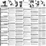
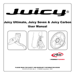
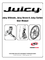
Juicy Ultimate, Juicy Seven & Juicy Carbon
User Manual
Please read the safety and warranty information inside
95-5015-010-000, Rev. A © SRAM Corporation • 2007
English
Juicy™ Ultimate, Juicy Seven & Juicy Carbon User Manual
Juicy™ Ultimate, Juicy Seven & Juicy Carbon User Manual
English
Make sure you have the right brackets
Congratulations!
AV I D
AV I D
You have selected the best hydraulic disc brakes your money can buy! This manual contains important information for installing
and setting up and adjusting your new brakes. To ensure that your Avid brakes perform properly, we recommend that you have
them installed by a qualified bicycle mechanic. We also urge you to follow all of our recommendations to help make your riding
experience safe, enjoyable and trouble free.
CPS
First, here is some information to get you started:
Hardware
Brackets
U LT I M AT E
TRI-ALIGN™ CALIPER POSITIONING SYSTEM™
Rear
Avid disc brakes use a unique alignment system called Tri-align Caliper
Positioning System (CPS). These stacks of concave and convex washers allow
the caliper to be perfectly aligned with the rotor, regardless of imperfections in the
mounting tabs on the fork or frame, giving you full, square pad contact.
Front
Pad Break-In
t
0 0 un
-3 Mo
02 ost
23
37 t P
5 - on
11 5 Fr
18
00 d
- 9 de
02 x tr u
63
37 o n t E
511 0 Fr
16
00 d
-5
02 orge
61
37 o n t F
511 0 Fr
16
00 d
-9
02 orge
21
37 t F
5 - on
11 5 Fr
18
CPS Bolt
00
-2 d
02 ge
62 or
37 r F
5 - ea
11 0 R
16
It may take anywhere from 20 to 40 complete stops to break in Avid pads. You
may begin to notice an increase in braking power after the first ride. Brake noise
can occur not only during the break-in period but off and on throughout the life
of the brake pads. Noise is dependent upon factors such as brake setup, rider
weight, riding style, braking style, and riding conditions (i.e. dust, soil, moisture,
and contamination of friction surfaces).
CHANGING HOSE LENGTHS & BLEEDING
Changing hose lengths and bleeding Avid disc brakes requires the Avid Bleed Kit.
Please contact your local bike shop or www.avidbike.com for details.
TOOLS NEEDED
• 2, 2.5, 4 and 5mm hex wrenches
• T-25 TORX® wrench
• 10mm open-end wrench
• Adjustable torque wrench: 2.8-10Nm (25-90 in-lb) range
• Safety glasses
U LT I M AT E
TOOLS NEEDED
• 2, 4 and 5mm hex wrenches
• T-25 TORX® wrench
• 10mm open-end wrench
• Adjustable torque wrench: 2.8-10Nm (25-90 in-lb) range
• Safety glasses
60
2 .0
. 01 s t
15 Po
. 5 3 nt
0 0 3 Fro
2 0 unt
Mo
00
0
20
2 .0
. 01 s t
15 Po
. 5 3 nt
0 0 Fro
5
18 unt
Mo
2.3
.6 0
73 o nt
r
.53
11 20 F
QR
4
2 .0
. 01 t
n
15
.5 3 Fro
0 0 3 IS
20
00
2 .6 er
.50 X X
73 t B o
n
.53
11 3 Fro
20
30
2 .0 er
. 01 X X
15 Bo
. 5 3 nt
0 0 Fro
5
18
© SRAM Corporation • 2007
00
2 .0
. 01 t
15
n
.5 3 Fro
0 0 IS
5
18
00
2.9
.3 0
76 o n t
.5 3 Fr
11 IS ear E)
0
R
16 IS CO D
0
14 c ept
(ex
0
5
2 .0
. 01
15 ar
. 5 3 Re
0 0 3 IS
20
0
95-5015-010-000 Rev. A
10
2 .0
. 01
15 ar
. 5 3 Re
0 0 IS
5
18
0
2 .6
.40
76 a r
. 5 3 Re
11 IS
0
16
English
Juicy™ Ultimate, Juicy Seven & Juicy Carbon User Manual
SAFETY INFORMATION
Brakes are a safety-critical item on a bicycle. Improper setup
or use of brakes can result in loss of control or an accident,
leading to a severe injury.
Avid disc brakes are designed as a system. Do not use
components from a manufacturer other than Avid within
the system.
Avid brakes are a performance product that offer increased
stopping power over brakes that you may be use to. This
greater power requires less effort to lock-up a wheel when
braking. A wheel lockup might cause you to lose control and
possibly cause injury.
Avid disc brake rotors are compatible with 44mm, 6-bolt
international standard disc hubs.
It’s your responsibility to learn and understand proper
braking techniques. Consult the owner’s manual for your
bicycle and a professional bike dealer.
Practice your riding and braking techniques on a flat and
level surface prior to aggressive riding.
The effectiveness of braking is dependent on many
conditions over which SRAM has no control. These include
the speed of the bicycle, type and condition of riding surface,
braking lever force, proper installation and maintenance
of brakes, brake lines, hydraulic fluid, levers, brake pads,
condition of the bike, weight of the rider, proper braking
techniques, weather, terrain, and a variety of other factors.
Avid brakes and levers are not intended for use on any
motorized bicycle or vehicle. Such use could result in a
serious personal injury.
ALWAYS RIDE UNDER CONTROL
Remember, it takes longer to stop in wet conditions. To
reduce the possibility of an accident and minimize trail
erosion, you should avoid locking-up your wheels.
1
English
Install rotor
Mount the rotor to the hub using the supplied T-25 TORX® bolts and tighten to the
specified torque. Avid logo MUST face out. Install the wheel into the fork or frame.
TORQUE TO:
6.2 Nm (55 in-lb)
We recommend 32 or 36-spoke wheels with a 3 or 4
cross spoke lacing pattern. Contact your specific wheel
manufacturer for more specifications.
DO NOT USE RADIALLY SPOKED WHEELS.
Use only DOT 4 or DOT 5.1 fluids with
AVID disc brakes.
Do not use a fluid other than the DOT fluids suggested.
Doing so will damage the system and make the brakes
unsafe to use.
2
MOUNT FRONT CALIPER
Mount the front caliper (shorter hose) to the fork.
Post Mount
i.s. MOUNT
DOT fluids will damage painted surfaces. If any fluid
comes in contact with a painted surface (i.e. your frame),
wipe it off immediately and clean with isopropyl alcohol.
or
Do not allow any brake fluid to come in contact with
the brake rotors. If this occurs, clean the rotors with
isopropyl alcohol.
Remove...
Do not allow any brake fluid to come in contact
with the brake pads. If this occurs, the pads are
contaminated and must be replaced.
...then mount direct
TORQUE TO:
9-10 Nm (80-90 in-lb)
Warning
Do not touch the braking surface of any rotor with your bare
hands, because the oils from your fingers will degrade its
performance. Always wear gloves, or handle the rotor by
its spokes.
Juicy™ Ultimate, Juicy Seven & Juicy Carbon User Manual
Disc brakes become very hot during use. Do not touch
the caliper or rotor immediately after use. Make sure the
brake has cooled down before making any adjustments.
95-5015-010-000 Rev. A
Loosen before
mounting
I.S. mount
Loosen the CPS bolts, then bolt the caliper to the mounting
tabs. Tighten the mounting bolts to the specified torque.
Check that the caliper moves freely on the CPS hardware.
© SRAM Corporation • 2007
Snug, then back off
1/8th to 1/4th turn
Post Mount
Remove the mounting bracket but leave the CPS bolts
and washer stacks intact. Bolt the caliper directly to the
fork. Snug the bolts, then back them out 1/8th to 1/4th turn.
Check that the caliper moves freely on the CPS hardware.
English
3
Juicy™ Ultimate, Juicy Seven & Juicy Carbon User Manual
Juicy™ Ultimate, Juicy Seven & Juicy Carbon User Manual
Loosen before
mounting
Check that the bars turn freely.
If there is excess hose in this
area, see the instructions on
changing hose lengths and
bleeding the system
MOUNT REAR CALIPER
Loosen the CPS bolts, then mount the rear caliper (longer hose) to the I.S. tabs
on the rear of the bike. Tighten the mounting bolts to the specified torque.
Check that the caliper moves freely on the CPS hardware.
5a
RIGHT-HAND FRONT (optional)
To run moto-style (right-hand front), just remove the clamps
from both levers, swap the the levers and reinstall the clamps,
arrows face up, as in step 5. Be sure to flip the pad engagement
adjustment bolt as well. Simply remove the E-clip from the pivot
assembly, remove the bushing and flip. Replace the E-clip.
TORQUE TO:
9-10 Nm (80-90 in-lb)
4
English
5a
RIGHT-HAND FRONT (optional)
To run moto-style (right-hand front), remove the E-Clip from
the bottom of the pivot assembly. Then remove the Speed
Dial knob, remove the bushing, and swap. Replace the E-Clip.
Flip the clamps over so the arrows face up, then mount as in
step 5.
ADJUST HOSE ANGLE, THEN ROUTE
If necessary, slightly loosen the banjo bolts on the calipers with an
8mm open-end wrench and rotate the fittings for optimal routing.
Re-tighten the banjo bolts to the specified torque, then route the
hoses. Make sure there is enough hose at critical points to allow for
suspension movement, but also make sure there aren’t any big loops
of extra hose. Now, secure the hoses to the frame and fork.
Swap
RE-TORQUE TO:
5.5-6.2 Nm
(50-55 in-lb)
Remove, then
re-install
Swap
Remove, then
re-install
U LT I M AT E
5
MOUNT LEVERS
Mount the levers onto the handlebar in the proper position. Arrows must point up. Make sure there is enough
hose for the handlebar to turn freely side to side. Tighten the top bolt completely to the specified torque
so there is no gap. Tighten the bottom bolt to the same torque.
No Gap
Mount levers with
arrows facing up
TORQUE TO:
2.8-3.4 Nm
(25-30 in-lb)
6
ALIGN AND TRUE CALIPERS
Squeeze the front lever 5 or 6 times, then hold. Compress the lever (with your hand
or a rubber band), then snug the CPS bolts enough to hold the caliper in place.
Spin the wheel and check for rotor drag. If there is drag, loosen the
CPS bolts and repeat. Once there is no drag, torque the CPS
bolts in an alternating fashion to the specified torque.
Repeat the procedure for the rear brake.
TORQUE TO:
8-10 Nm
(70-90 in-lb)
(in an alternating fashion)
Gap
95-5015-010-000 Rev. A
© SRAM Corporation • 2007
English
7
Juicy™ Ultimate, Juicy Seven & Juicy Carbon User Manual
Juicy™ Ultimate, Juicy Seven & Juicy Carbon User Manual
English
PAD REPLACEMENT
ADJUST REACH
One “click” of the 2mm hex
reach adjust screw here...
Use a 2mm hex wrench to adjust the reach if necessary.
One click equals 1mm of adjustment.
1. PUSH THE PISTONS BACK IN
As the Juicy calipers are self-adjusting, the pistons need to be pushed back into the
body to their original position before the new pads can be installed. The safest way to
do this is with the old pads still in the caliper to protect the pistons. Place a flat-blade
screwdriver between the old pads, then carefully rock it back and forth, pushing the
pistons back into their bores.
If using twist-shifters, it will be necessary to slide the levers away from
the shifters or remove them completely to access the reach adjustment
screw. Re-torque the lever clamp bolts as notec in step 5 after adjusting
the lever reach.
2. REMOVE THE OLD PADS
Grab one of the pad tabs and slide the pad toward the center of the caliper (this
disengages the pad backing plate from the post in the center of the piston), then
pull the pad straight out. Repeat for the other pad. Note: The spreader clip that
sits in between the pads may not come out with the second pad. If not, push
it out from the open top of the caliper with your little finger.
...equals 1mm of
adjustment here
8
ADJUST pad engagement point
Now it’s time to set the pad contact point exactly where
it feels best for your hand. Experiment by using a 2.5mm
hex wrench to turn the red adjuster both ways, to see what
different settings feel like. Then, chose the spot that you
prefer. You can change the setting whenever you want.
Tip: Your RockShox rebound adjuster is a 2.5mm hex
wrench.
8
ADJUST pad engagement point
Use the Speed Dial pad engagement knob to adjust the
engagement point exactly where you want it. Turning the
knob towards the stem increases the amount of lever travel
necessary for the pads to contact the rotor. Experiment and
see what the different settings feel like. The goal is for your
brake pads to engage right where your grip on the lever feels
the strongest.
Note: The Speed Dial knob can turn a total of 20
revelutions
This way for quicker
engagement
OUT:
The lever will be further from
the handlebar.
Be sure the spreader clip is oriented to the pads as shown
below. Squeeze the pad and clip assembly together, then
insert into the caliper as a unit. Firmly push until the
assembly “clicks” into place.
Tip: To ease intallation, hold your thumb over the pad retainer
clip on the open top of the caliper while inserting the new pad
and spreader.
hydraulic disc brake hose length adjustment and bleeding
Avid Hydraulic Disc Brakes come with hoses already attached in an “average” length. The system has already been bled,
so if you don’t need to change the hose length, then you are ready to ride.
Left
IN:
The lever will be closer to
the handlebar.
3. INSTALL THE NEW PADS AND SPREADER
This way for quicker
engagement
If however, you do need to change hose lengths, you will need an Avid Bleed Kit or we recommend you have a professional
bicycle mechanic perform the service for you. Avid Bleed Kits provide complete instructions and Avid tools for adjusting the
hose length as well as bleeding the brake system. The instructions are also available online at www.sram.com or
www.avidbike.com.
Right
U LT I M AT E
95-5015-010-000 Rev. A
© SRAM Corporation • 2007
English
Juicy™ Ultimate, Juicy Seven & Juicy Carbon User Manual
Juicy™ Ultimate, Juicy Seven & Juicy Carbon Bedienungsanleitung
Deutsch
SRAM Corporation Warranty
Extent of Limited Warranty
SRAM warrants its products to be free from defects in materials or
workmanship for a period of two years after original purchase. This
warranty only applies to the original owner and is not transferable.
Claims under this warranty must be made through the retailer where
the bicycle or the SRAM component was purchased. Original proof of
purchase is required.
Local law
This warranty statement gives the customer specific legal rights. The
customer may also have other rights which vary from state to state
(USA), from province to province (Canada), and from country to
country elsewhere in the world.
To the extent that this warranty statement is inconsistent with the local
law, this warranty shall be deemed modified to be consistent with such
law, under such local law, certain disclaimers and limitations of this
warranty statement may apply to the customer. For example, some
states in the United States of America, as well as some governments
outside of the United States (including provinces in Canada) may:
a.Preclude the disclaimers and limitations of this warranty
statement from limiting the statutory rights of the consumer
(e.g. United Kingdom).
b.Otherwise restrict the ability of a manufacturer to enforce such
disclaimers or limitations.
Limitations of Liability
To the extent allowed by local law, except for the obligations specifically
set forth in this warranty statement, In no event shall SRAM or its thirdparty suppliers be liable for direct, indirect, special, incidental, or
consequential damages.
Limitations of Warranty
• This warranty does not apply to products that have been incorrectly
installed and/or adjusted according to the respective SRAM technical
installation manual. The SRAM installation manuals can be found online
at www.SRAM.com, www.rockshox.com or www.avidbike.com.
• This warranty does not apply to damage to the product caused
by a crash, impact, abuse of the product, non-compliance with
manufacturer’s specifications of usage or any other circumstances in
which the product has been subjected to forces or loads beyond its
design.
• This warranty does not apply when the product has been modified.
• This warranty does not apply when the serial number or production
code has been deliberately altered, defaced or removed.
• This warranty does not apply to normal wear and tear. Wear and tear
parts are subject to damage as a result of normal use, failure to service
according to SRAM recommendations and/or riding or installation in
conditions or applications other than recommended.
10
Wear and tear parts are identified as:
- Dust seals
- Bushings
- Air sealing o-rings
- Glide rings
- Rubber moving parts
- Foam rings
- Rear shock mounting hardware
and main seals
- Stripped threads/bolts (aluminum,
titanium, magnesium or steel)
- Upper tubes (stanchions)
- Brake sleeves
- Brake pads
- Chains
- Sprockets
- Cassettes
- Shifter and brake cables (inner
and outer)
- Handlebar grips
- Shifter grips
- Jockey wheels
- Disc brake rotors
- Tools
Juicy Ultimate, Juicy Seven & Juicy Carbon
Bedienungsanleitung
• This warranty shall not cover damages caused by the use of parts of
different manufacturers.
• This warranty shall not cover damages caused by the use of parts
that are not compatible, suitable and/or authorized by SRAM for use
with SRAM components.
• This warranty shall not cover damages resulting from commercial
(rental) use.
SRAM Corporation
1333 North Kingsbury, 4th Floor, Chicago, Illinois 60622
1-312-664-8800 • fax 1-312-664-8826
www.avidbike.com
95-5015-010-000 Rev. A
BITTE BEACHTEN SIE DIE INNENSEITIGEN SICHERHEITS- UND GARANTIEINFORMATIONEN
95-5015-010-000, Rev. A © SRAM Corporation • 2007
© SRAM Corporation • 2007
11