1
12843 Foothill Blvd.,
Suite D
Sylmar, CA 91342
818 898 3380 voice
818 898 3360 fax
www.dnfcontrols.com
Model No. 4040CL-L-PBIO
(& 4040CL-L-T-PBIO)
300 CLIP FAST ACCESS SYSTEM
Louth Protocol
With Peripheral Bus Interface
Option
User Manual
TABLE OF CONTENTS
I.
REVISION HISTORY .........................................................................3
Getting Started ..............................................................................................4
II.
SYSTEM DESCRIPTION .....................................................................4
III.
SYSTEM INSTALLATION ...................................................................5
IV.
CONNECTION DIAGRAM ...................................................................6
V.
VIDEO SERVER SETUP ......................................................................7
VI.
LOAD A CLIP.....................................................................................7
VII.
LEARN A CLIP OR CLIP COMBINATION .............................................8
VIII.
RECALL A CLIP OR CLIP COMBINATION .........................................10
IX.
RECUE CLIP ....................................................................................10
X.
GOTO TIME .....................................................................................10
XI.
CLEAR CUE POINTS ........................................................................11
XII.
PLAY CLIP (SEGMENT) ...................................................................11
XIII.
LOOP CLIP (SEGMENT) ...................................................................11
XIV.
PBIO ENABLE/DISABLE..................................................................12
XV.
BVW PROTOCOL .............................................................................12
XVI.
PRODUCTION SWITCHER PBIO TRIGGER VALUES ..........................13
Advanced Features.......................................................................................14
XVII.
CREATE A CLIP ...............................................................................14
XVIII.
REALIGN GANGED CHANNELS ........................................................14
XIX.
CREATE A SUBCLIP (FOR LOUTH ONLY) .........................................14
XX.
CAPTURE ........................................................................................15
XXI.
CREATE CUE POINT LABELS............................................................16
4040CL-L, 300 Clip Fast Access System, Louth Protocol, PBIO Option
Page 1 of 29
Reference.....................................................................................................17
XXII.
SETUP MENU ..................................................................................17
XXIII.
FUNCTION TABLE ...........................................................................20
XXIV.
SPECIFICATIONS............................................................................22
XXV.
TROUBLESHOOTING .......................................................................23
XXVI.
SCREEN SHOTS ...............................................................................24
XXVII.
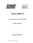
KEY LAYOUT ...................................................................................27
XXVIII. DNF CONTROLS LIMITED WARRANTY.............................................28
Manual Version...........…........................….......1.11 052606
Document ID.................. 4040CL-L-PBIO_User_Manual.doc
Page 2 of 29
4040CL-L, 300 Clip Fast Access System, Louth Protocol, PBIO Option
I.
REVISION HISTORY
080205
1.0
Original document.
030206
1.1
Minor Corrections
052606
1.11
Updated dimensions for T-Bar and Non T-bar housings.
Added screen shots.
4040CL-L, 300 Clip Fast Access System, Louth Protocol, PBIO Option
Page 3 of 29
GETTING STARTED
II. SYSTEM DESCRIPTION
The 4040CL system includes DNF’s most robust controller, the ST400, with
Cliplist software. The ST400 controls up to 6 video channels individually or
ganged. It features full transport functionality.
The 4040CL provides fast access to fill clip and key clip combinations with the
press of one key.
The 4040CL-L supports Louth (VDCP) protocol and requires that the Video
Server be controllable under VDCP Protocol.
The 4040CL provides fast access to existing video clips stored in the Grass
Valley Group PROFILE, the Leitch VR, and other Video Servers supporting
VDCP Protocol.
The 4040CL-L also allows VTR control on select channels.
Definitions
Throughout this document, DDR, VDR & Video Server will be referred to
collectively as “Video Server.”
Words surrounded by brackets, for example, [ENTER], are keys on the
ST400.
[XXX] + [XXX] means hold the two keys down simultaneously.
The 6 keys directly below the display are referred to as “Softkeys,” for
example {EXIT}. Their function changes as indicated on the last line of the
display.
Page 4 of 29
4040CL-L, 300 Clip Fast Access System, Louth Protocol, PBIO Option
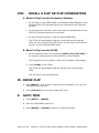
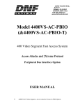
III. SYSTEM INSTALLATION
A. ST400, VTR/DDR CONTROLLER
1. Plug one end of a 9-conductor, RS422 serial cable into the VTR1 (VTR2,
VTR3, VTR4, VTR5 or VTR6 connector on the rear of the ST400. Plug
the other end of the cable into the 9-pin REMOTE connector on the
Video Server.
2. Connect the supplied POWER SUPPLY, APX#4108, into the POWER
connector on the rear of the ST400. Plug the Power Supply into an
outlet, 90 VAC - 240 VAC.
3. Plug in a Black Burst Reference Video Source into REF. VIDEO IN
connector on the back of the ST400 using a BNC cable.
4. Check SETUP MENU prior to using the ST400 to confirm proper Record
mode and other User settable modes.
B. PRODUCTION SWITCHER
1. Plug one end of a 9-conductor, RS422 serial cable into the “PBIO”
connector on the rear of the ST400. Connect the other end of the cable
to the Peripheral Bus Connector on the production switcher.
2. Refer to “SETUP MENU” section to set VTR1, VTR2, VTR3, VTR4, VTR5,
& VTR6 Pbus Device Addresses, PBIO parity to match the Production
Switcher, and Production Switcher type.
The Pbus baud rate must be set to “38400” on the Production Switcher.
3. Configure the production switcher:
On the production switcher Enable the Peripheral Bus.
Enable the Peripheral Device Addresses assigned to the ST400.
Enable the appropriate Learn/Recall levels.
Enable the Timeline or Recall Trigger function.
Installation is complete.
4040CL-L, 300 Clip Fast Access System, Louth Protocol, PBIO Option
Page 5 of 29
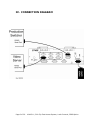
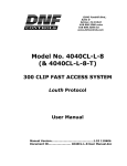
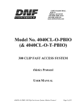
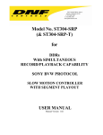
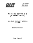
IV. CONNECTION DIAGRAM
Page 6 of 29
4040CL-L, 300 Clip Fast Access System, Louth Protocol, PBIO Option
V.
VIDEO SERVER SETUP
A. Select Louth Broadcast communications protocol on the VIDEO SERVER to
be controlled.
B. Assign a serial port on the VIDEO SERVER through which the ST400 will
control it.
NOTES: In Louth mode, the VIDEO SERVER
and ASSEMBLE record modes are disabled.
ONLY
allows Full Record. INSERT
Setup is complete
VI. LOAD A CLIP
A. Select a VTR by pressing VTR [1], [2], [3], [4], [5] or [6].
B. Press [CLIP LIST] to view the list of CLIP IDs that are resident on the
Video Server. The CLIP LIST indicator will turn on.
C. Press {CREATE} to create and load a new clip.
(Creating a clip is described in the CREATING A CLIP section.)
OR
Turn the Wheel to view the existing CLIP IDs on the video server.
Turn the Wheel clockwise to scroll forward, or counter-clockwise to scroll
backward, through the list of available CLIPs.
OR
Press [ENTER] to start manually entering a CLIP ID using the ST400
numeric keypad, or PC keyboard.
D. Press [LOAD] to load the entered CLIP ID for playout.
E. Repeat steps a. thru d. to load clips on desired VTRs.
F. Set the Gang Mode, if required. See “GANG SETUP” in FUNCTION TABLE
section.
4040CL-L, 300 Clip Fast Access System, Louth Protocol, PBIO Option
Page 7 of 29
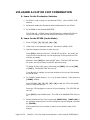
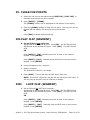
VII.LEARN A CLIP OR CLIP COMBINATION
A. Learn On the Production Switcher
1. On ST400, Load a clip(s) on the desired VTR(s). (See “LOAD A CLIP”
section)
2. Select and enable the Peripheral Device Addresses for the ST400.
3. Do a LEARN to the desired REGISTER.
The ST400 will: LEARN (save) the VTR number, loaded CLIP ID and
current IN & OUT time into the REGISTER number in the ST400.
B. Learn On the ST400 (Louth Mode)
1. Press VTR [1], [2], [3], [4], [5] or [6].
2. Load a clip on the selected channel. See section LOAD A CLIP.
3. Use the transport functions to view the clip.
Press [IN] to mark an IN point. The IN LED will blink. On recall, the
clip will cue to the IN time, not the beginning of the clip and the LED
will stay on steady.
Optional- Press [OUT] to mark an OUT point. The OUT LED will blink.
On recall, the clip will play to the OUT point then stop.
To delete an IN or OUT point, press and hold [DEL], then press [IN]
or [OUT]. The IN/OUT LED will turn off.
If no IN point is marked, the current location of the clip will be learned
as the IN point.
4. For GANGs, repeat steps 1), 2), or 3) for each channel. Then press the
{GANG} softkey.
Press VTR [1], [2], [3], [4], [5] or [6] to add the VTR to the GANG.
The VTR LED will turn on.
Press the VTR key again to remove it from the gang. The VTR LED will
turn off.
Press [ESC] to exit GANG mode. The LED of all GANGed VTRs will turn
on.
5. Select the desired Cue Point by pressing [NEXT CUE], [LAST CUE] or
by manually entering the Cue Point using the numeric keypad, followed
by [ENTER].
The selected Cue Point number is shown on the bottom part of the
display.
Page 8 of 29
4040CL-L, 300 Clip Fast Access System, Louth Protocol, PBIO Option
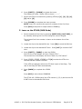
6. Press [SHIFT] + [LEARN] to initiate the Learn.
The display will show: “Select VTRs to learn:--------”
7. Select the VTRs to be learned by pressing VTR keys [1], [2], [3], [4],
[5] and/or [6].
8. Press [LEARN] to complete the Learn process.
NOTE: Learn will overwrite the previous contents of the Cue Point.
Press [ESC] at anytime to escape without LEARNing.
C. Learn on the ST400 (BVW Mode)
1. Select the desired Cue Point by pressing [NEXT CUE], [LAST CUE], or
by manually entering the Cue Point using the numeric keypad.
The selected Cue Point number is shown on the bottom line of the
display.
2. Locate the clip to the desired IN time. Press [IN] to mark the IN time.
3. Locate the clip to the desired OUT time. Press [OUT] to mark the OUT
time.
4. Press [SHIFT] + [MARK] to start the LEARN.
The first line of the display will show “Select VTRs:”
The second line of the display will show “Mark-Lrn, ESC-cancel.”
5. Press VTR[1], VTR[2], VTR[3] or VTR[4] to select the VTR to be
learned into the current Cue Point.
If the VTRs are ganged, select one VTR that is part of the Gang. The
rest of the Gang will learn automatically.
6. Press [MARK] to complete the LEARN.
OR
Press [ESC] to exit without LEARNING.
The ST300 will: LEARN (save) the VTR number (1,2,3,4) and current IN
& OUT time to the selected Cue Point.
4040CL-L, 300 Clip Fast Access System, Louth Protocol, PBIO Option
Page 9 of 29
VIII.
RECALL A CLIP OR CLIP COMBINATION
A. Recall A Clip From the Production Switcher
1. On the ST400 in the SETUP MENU, set the desired PB addresses for the
selected ST400 VTR channels that will be controlled by the Production
Switcher.
2. On the Production Switcher, select and enable the PB addresses for the
ST400 VTR channels that will be controlled.
3. On the Production Switcher, recall the desired REGISTER.
The ST400 will automatically load the Learned clips on the Learned
VTRs, set the Learned IN and OUT points, cue the clips to the Learned
IN point, set the Learned GANG mode.
B. Recall A Clip From the ST400
1. Select the desired Cue Point by pressing [NEXT CUE], [LAST CUE] or
by manually entering the Cue Point using the numeric keypad.
The selected Cue Point number is shown on the bottom of the display.
2. Press [LOAD] on the ST400.
The ST400 will automatically load the learned clips on the learned
VTRs.
Cue the clips to the learned IN time.
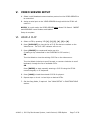
IX. RECUE CLIP
A. Press [RECUE]. If an IN Point is marked (the IN indicator is on), the clip
will RECUE to the IN Point.
B. Press {CUE OUT} to cue to the marked OUT point.
X.
GOTO TIME
A. Press [SHIFT] + [RECUE].
B. Enter the TIMECODE to search to.
C. Press [ENTER] or [RECUE] to search to entered Timecode.
Page 10 of 29
4040CL-L, 300 Clip Fast Access System, Louth Protocol, PBIO Option
XI. CLEAR CUE POINTS
A. Select the cue point to be cleared using [NEXT CUE], [LAST CUE], or
manually entering the cue point number.
B. Press [SHIFT] + [LEARN].
The {CLEAR} softkey will be displayed on the bottom of the display.
C. Press the {CLEAR} softkey to clear the cue point. The cue point will be
cleared and the display will return to the normal screen.
OR
Press [ESC] to escape without clearing.
XII.PLAY CLIP (SEGMENT)
A. Set an IN Point and OUT Point.
Jog/Shuttle to the desired IN point. Press [IN]. The IN LED will blink.
Jog/Shuttle to the desired OUT point. Press [OUT]. The OUT LED will
blink.
OR
Press [SHIFT] + [IN]. Manually enter the IN time on the numeric
keypad. Press [ENTER].
Press [SHIFT] +[OUT]. Manually enter the OUT time on the numeric
keypad. Press [ENTER].
B. Learn the segment into a cuepoint.
C. Recall a cuepoint.
The IN and OUT LEDs turn on steady.
D. Press [PLAY]. The clip will play the OUT point, then stop.
NOTE: If IN & OUT LEDs blink, the clip will not stop at the OUT point. It
will only stop at the OUT point of LEDs are on steady.
XIII.
LOOP CLIP (SEGMENT)
A. Set an IN Point and OUT Point (optional).
Jog/Shuttle to the desired IN point. Press [IN]. The IN LED will blink.
Jog/Shuttle to the desired OUT point. Press [OUT]. The OUT LED will
blink.
OR
Press [SHIFT] + [IN]. Manually enter the IN time on the numeric
keypad. Press [ENTER].
Press [SHIFT] + [OUT]. Manually enter the OUT time on the numeric
keypad. Press [ENTER].
4040CL-L, 300 Clip Fast Access System, Louth Protocol, PBIO Option
Page 11 of 29
B. Learn the segment into a cuepoint.
C. Recall a cuepoint.
The IN and OUT LEDs turn on steady.
D. Press [LOOP ENABLE]. The clip will loop between IN and OUT (if set). If
no IN and OUT are set, the complete clip is looped.
XIV.
PBIO ENABLE/DISABLE
On the ST400 press the {PBIO} softkey to enable or disable PBIO. When
disabled, the ST400 will ignore all Pbus commands. When enabled, the ST400
will respond to all Pbus commands.
When enabled and Pbus commands are received, the softkey’s LED will flash.
XV. BVW PROTOCOL
A. Press [MENU].
B. Turn the wheel until “Protocol” is highlighted.
C. Select {BVW} protocol if you wish to control tape machines with the
selected channel.
D. All the functions described in the manual are available in BVW protocol
except:
-
Cliplist
Clip Create
Loop
Play Segment
Subclip
When a Learn is performed in BVW protocol, only the IN, OUT and gang
information is stored.
NOTE: BVW and Louth channels cannot be ganged together.
Page 12 of 29
4040CL-L, 300 Clip Fast Access System, Louth Protocol, PBIO Option
XVI.
PRODUCTION SWITCHER PBIO
TRIGGER
VALUES
The Production Switcher outputs a Peripheral Bus trigger at specific Timeline
key frames, as programmed by the operator. The 4040CL performs a specific
function for each trigger value:
GRASS VALLEY GROUP Production Switcher
Trigger Value
0
1
2
3
4
5
6
7 or greater
Mode
Play (If OUT point is specified, stop at OUT.
If clip ends with “*”, Loop Play.)
Recue to beginning of clip
Slo-mo using ST400 Preset Speed
Reverse Play
Still Frame
Loop (Louth mode only)
Record
Play
SONY Production Switcher
Trigger Value
0
1
2
3
4
5
6
7 or greater
Mode
Recue to beginning of clip Play
Play (If OUT point is specified, stop at OUT. If clip ends
with “*”, Loop Play)
Slo-mo using ST400 Preset Speed
Reverse Play
Still Frame
Loop (Louth mode only)
Record
Play
To control more than one VTR, enable the Peripheral Device Address for each
VTR. The Trigger value will be sent to the enabled devices.
OR
GANG the required VTRs on the ST400. See “FUNCTION TABLE” section for
GANG instructions. Enable the Peripheral Device Address for one of the
GANGed VTRs. The Trigger will be sent to the enabled VTR. The other VTRs
in the GANG will perform the same action.
4040CL-L, 300 Clip Fast Access System, Louth Protocol, PBIO Option
Page 13 of 29
ADVANCED FEATURES
XVII.
CREATE A CLIP
A. In the Setup Menu, configure Louth port as Input Port.
B. Press [CLIP LIST].
C. Press {CREATE}. The display will show the default CLIP ID.
D. Press {LOAD} to accept the default CLIP ID.
OR
Manually enter an ID with a maximum of 32 characters from the ST400
numeric keypad.
OR
Manually enter an ID with a maximum of 32 characters from a PC
keyboard.
E. Press {LOAD}. The clip will be created and loaded.
If the entered CLIP ID already exists, a warning message will be displayed.
To load the existing clip, press [ENTER]. Press [ESC] to exit without
loading the existing clip.
XVIII. REALIGN GANGED CHANNELS
When the channels are Jogged/Shuttled/Slomoed in gang, they may drift
apart. To bring the channels back to their initial offsets, press [SHIFT] +
[STOP].
XIX.
CREATE A SUBCLIP (FOR LOUTH ONLY)
A. Load a clip as described in Section VI, LOAD A CLIP section.
B. Mark (enter) an IN and OUT point.
C. Press [SHIFT] + [CLIPLIST].
D. Enter a new clip name using a PC keyboard or a numeric keypad.
E. Press [ENTER].
F. The new clip is created. The new clip has entered name. It’s SOM is the
IN point and EOM is the OUT point.
Page 14 of 29
4040CL-L, 300 Clip Fast Access System, Louth Protocol, PBIO Option
XX. CAPTURE
A. Select BVW protocol to control the source channel (see SETUP MENU).
B. Select LOUTH protocol to control the destination channel (see SETUP
MENU).
C. Mark (Enter) an IN and OUT point on the source channel.
D. Enter a destination channel (see SETUP MENU).
E. Enter Preroll Time (see SETUP MENU).
F. Enter Record Delay (see SETUP MENU).
G. Select a source channel (press a corresponding [VTR] key).
H. Press [SHIFT] + [RECORD].
I.
Enter the new clip name using a PC keyboard or a numeric keypad.
J. Press [ENTER].
The VTR gets prerolled to the IN point. At the IN point the recorder starts
recording.
At the OUT point the recorder stops. The new clip with the specified name
is created.
4040CL-L, 300 Clip Fast Access System, Louth Protocol, PBIO Option
Page 15 of 29
XXI.
CREATE CUE POINT LABELS
Use LABELS mode to assign meaningful names to cue points. LABELS provides
a faster and easier method to select cue points.
A. On the ST400
1. In Setup Menu, turn LABEL MODE on.
2. Select cue point to label.
3. Press the [LABEL] key.
4. Manually enter a label, up to 8 characters in length, using the numeric
keypad, or PC keyboard.
5. Press the [ENTER] to assign the entered label to the selected cue
point.
OR
[ENTER] on the PC keyboard.
OR
[NEXT CUE] or [LAST CUE].
NOTE: Labels are saved in non-volatile memory in the ST400. They
are not saved in the video server.
Page 16 of 29
4040CL-L, 300 Clip Fast Access System, Louth Protocol, PBIO Option
REFERENCE
XXII.
SETUP MENU
Press [MENU]. The MENU indicator will turn on.
The display will show the following parameters with their current settings.
Turn the wheel to select a menu option.
Press the {CHANGE} softkey to modify the current setting.
Press the {EXIT} softkey to exit the Setup Menu.
PARAMETER
LOUTH PORT
DESCRIPTION
Enter the controlled channel’s Louth port number (1 - 9) on the numeric
keypad. Then press the {INPUT} or {OUTPUT} softkey. An INPUT is
indicated by ‘-‘ before the port number.
To CREATE (RECORD) clips, an INPUT channel must be selected.
To playout CLIPS, an OUTPUT channel must be selected.
Enter ‘0’, to turn off the port.
PROTOCOL
Select {LOUTH} if you’re controlling a video server.
Select {BVW} to control a VTR.
STANDARD
{NTSC} or {PAL} softkey.
WIND MODE
{HOLD}
(Fast wind is maintained only while key is depressed.)
OR
{LATCH}
(Fast wind is initiated and maintained with momentary key press.)
{SPEED}
Press the softkey to change the speed setting (3.9, 6.0, 8.1, 10.0, 23.7).
EXTENDED IDs
{ON} – Allow up to 32-character CLIP IDs.
{OFF} – Allow up to 8-character CLIP IDs.
RECORD MODE
Press a softkey to select the desired record mode: Lockout or Crash.
4040CL-L, 300 Clip Fast Access System, Louth Protocol, PBIO Option
Page 17 of 29
PARAMETER
DESCRIPTION
SLOMO
Press the {TBAR} (or {WHEEL}) softkey to select the T-bar or wheel for
slomo.
For T-bar:
The T-bar has a speed range of 0 Æ 2x with a detent at 1x play
speed
OR a range of 0 Æ 1x (detent at 1x play speed).
Press {SPD-RNG} softkey to toggle between SLOMO speed
ranges:
0 Æ 1x OR 0 Æ 2x.
Press {BACK} softkey to return to SLOMO MENU.
Press [ESC] to exit OR turn the Wheel to select another item.
For Wheel:
Press the {PRSET} softkey to toggle between UPDATE and STATIC
modes.
UPDATE: When exiting SLOMO mode, the last used speed is saved
in the Preset Speed register.
STATIC: The Preset Speed register is NOT updated when exiting
SLOMO mode. It is only changed by [SHIFT] + [SLOMO]
(PRESET SLOMO).
Press {SPD-RNG} softkey to toggle between SLOMO speed
ranges:
0 Æ 2x OR -1 Æ 2x.
RECALL MODE
Press {NORMAL} or {REDIR} (redirect).
NORMALThe cue point will load on the learned VTR.
REDIRWhen one and only one clip is learned into a Cue Point, the Clip will be
REDIRECTED to load on the currently selected VTR.
GANG MODE
{PERM} Permanent Gang –
The GANG can be created and undone only with the {GANG} softkey.
{TEMP} Temporary Gang –
The Gang is created by pressing {GANG} softkey, then selecting the
VTRs
to gang/ungang.
Quickly undo the GANG by pressing any VTR key.
Page 18 of 29
4040CL-L, 300 Clip Fast Access System, Louth Protocol, PBIO Option
PARAMETER
PLAY PREROLL
DESCRIPTION
Enter Play Preroll – the time it takes the server to start playout.
Used for LOOP function.
RECORD
PREROLL
Enter Record Preroll – the time it takes the server to start Record. Used
for capture.
PREROLL
Enter the Preroll time for the source VTR in Capture.
DESTINATION
CHANNEL
Select a Destination channel for capture. Must be a Louth channel.
PB ADDRESS
Select [VTR1], [VTR2], [VTR3], [VTR4], [VTR5], or [VTR6].
Assign Pbus Device Address to selected VTR by entering an address
between 0 and 23 using numeric keypad.
OR
Press DEL to turn off Pbus control for the VTR.
PB SWITCHER
Select {GRASS VALLEY} or {SONY} Production Switcher. For Philips,
use Grass Valley.
PBIO PARITY
Press {NONE}, {ODD} or {EVEN} parity to match the Pbus setting on
your Production Switcher.
SERVICE
{DEFAULTS} {CLEANUP} {BACK}
DEFAULTS
Set ST400 to factory defaults. Follow the prompts on the display.
Press {YES} to continue or press {NO} to exit without changing ST400.
CLEANUP
Clears all cue points in all banks. Follow the prompts on the display.
BACK
Return to prior menu item.
4040CL-L, 300 Clip Fast Access System, Louth Protocol, PBIO Option
Page 19 of 29
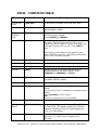
XXIII. FUNCTION TABLE
Function
Key Press
Description
CUE TO OUT
POINT
[CUE OUT]
If OUT point is marked, cue to the OUT point.
FFWD
[FFWD]
Press and hold to FFWD. Release key to stop. Set
WIND SPEED in MENU.
GO TO
ENTERED
TIME
[SHIFT] + [RECUE]
To search, manually enter the desired time on the
ST400’s numeric keypad.
Press [ENTER] or [RECUE].
GANG SETUP
[GANG]
Individually press the VTR keys to be included in
the gang. The LED above the key will turn on.
Press the VTR key again to remove from gang; the
LED above the key will turn off. Press [ESC] to
exit.
Upon exiting, all members of the gang will have
their VTR LEDs turned on. The flashing LED shows
which VTR is currently selected.
JOG
[JOG]
Select JOG mode and enable Wheel.
LAST CUE
[LAST]
Step to the previous Cue Point Location.
NEXT CUE
[NEXT]
Step to the next Cue Point Location.
RECORD
[REC]
Places VTR into the Record mode selected by
RECORD MODE in the SETUP MENU. Press
[RECORD] or [RECORD] + [PLAY].
REWIND
[RWD]
Press and HOLD to rewind. Release key to stop.
Set WIND SPEED in MENU.
SHUTTLE
[SHUTTLE]
Select SHUTTLE mode and enable Wheel.
SLOMO
[SLOMO]
STOP
[STOP]
Press [SLOMO] to slo-mo the VTR. Turn the
Wheel
(or move the T-bar, if available) to change the play
speed.
Press [SLOMO] to STILL frame
OR
press any transport key to exit SLOMO.
Press to stop the channel.
TIME MODE
SELECT
[TIME MODE]
Press to toggle between Timecode (TC), VITC (VT)
or Tape Timer (TM) display modes on a VTR and
between Remaining Time (RT) and Elapsed Time
(ET) on a Video Server.
PLAY
[PLAY]
If an OUT point is marked, play to the OUT point
and stop. If no OUT point is marked, play
normally.
Page 20 of 29
4040CL-L, 300 Clip Fast Access System, Louth Protocol, PBIO Option
Function
Key Press
Description
RECUE
[RECUE]
If the IN point is marked, cue to the IN point
PBIO ENABLE/
DISABLE
{PBIO}
PBIO LED is ON if PBIO is enabled. Toggle the key
to temporarily disable all PBIO signals. The key
blinks when a valid PBIO command is received from
the Production Switcher.
REALIGN
GANGED
CHANNELS
[SHIFT] + [STOP]
Search ganged channels to the appropriate time to
resynchronize them.
4040CL-L, 300 Clip Fast Access System, Louth Protocol, PBIO Option
Page 21 of 29
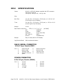
XXIV.
SPECIFICATIONS
Power:
90 VAC to 265 VAC adapter supplied with IEC connector
APX Model #AP4108
+5v @ 4A, +12v @ 1.0A, -12V @ 0.6A
Size:
Non-Tbar
(H x W x D) 1 3/4 (front) x 3 3/8 (rear) x 11 3/8 x 6 1/2
(8 5/8 high to top of display)
T-bar
(H x W x D) 1 3/4 (front) x 3 3/8 (rear) x 13 3/4 x 6 1/2
(8 5/8” high to top of display)
Weight:
10 lbs.
Rear Panel Connectors:
VTR1, 2, 3, 4, 5, 6, 7, 8
(All DB9F)
GPI
(DBF25F)
Power
(DB9M)
Keyboard
(6-pin mini DIN)
Ref. Video In
(BNC)
Ground
Threaded stud
Display:
Easy to read, back-lit LCD display
Jog/Shuttle Wheel:
With mechanical detents
RS422 SERIAL CONNECTOR
9-Pin D-Type, Female (DB9F)
Pin # 1
2
3
4
5
Frame Ground
Receive A Í
Transmit B Î
Transmit Common
Spare
6
7
8
9
Receive Common
Receive B Í
Transmit A Î
Frame Ground
POWER CONNECTOR
9-Pin D-Type, Female (DB9M)
Pin # 1
2
3
4
5
Page 22 of 29
+5v DC
+5v DC
Ground
+12 VDC
–12 VDC
6
7
8
9
+5 VDC
Ground
Ground
Ground
4040CL-L, 300 Clip Fast Access System, Louth Protocol, PBIO Option
GPI IN/OUT CONNECTOR
26-Pin D-Type, Female (DB26F)
Pin # Function
1
No Connection
2
No Connection
3
No Connection
4
No Connection
5
No Connection
6
No Connection
7
No Connection
8
No Connection
9
Ground
10
GPI #1 Play
11
GPI #2 Stop
12
GPI #3 Recue
13
GPI #4 Next Cue
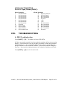
XXV.
Pin # Function
14
GPI #5 Last Cue
15
GPI #6 Recall
16
No Connection
17
No Connection
18
Ground
19
+5V
20
+5V
21
No Connection
22
No Connection
23
No Connection
24
No Connection
25
No Connection
26
Ground
TROUBLESHOOTING
A. PBIO Troubleshooting
Press [SHIFT] + [0]. The display will show PBIO DATA.
All Pbus commands received from the production switcher will be shown on the
display. Communication errors due to parity mismatch or baud rate mismatch
will be shown as ‘-‘. If no command data is shown, then no commands are
being received from the production switcher. Check the Production Switcher’s
Pbus set. Also check the cabling between the Production Switcher and ST400.
Press [SHIFT] + [0] to exit this test mode.
4040CL-L, 300 Clip Fast Access System, Louth Protocol, PBIO Option
Page 23 of 29
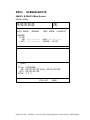
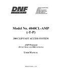
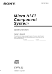
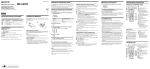
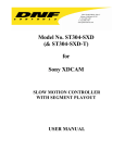
XXVI.
SCREEN SHOTS
4040CL & 2044CL Main Screen
(Not to scale)
TM 00:00:00:00
PLAY MODE:
VTR1
NORMAL
(REC MODE: LOCKOUT)
LOADED:
CLIP:
IN: --:--:--:-OUT: --:--:--:--
DUR:--:--:--:-SPEED: +0.00
Q000
Clip:
IN:
OUT:
VTRS:
CLIPNAME
00:00:00:00 DUR: 00:00:00:00
00:00:00:00
1 3 5
CUE-OUT
Page 24 of 29
GANG
4040CL-L, 300 Clip Fast Access System, Louth Protocol, PBIO Option
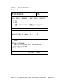
4040CL & 2044CL GANG Screen
(Not to scale)
TM 00:00:00:00
PLAY MODE:
VTR1
NORMAL
(REC MODE: LOCKOUT)
LOADED:
CLIP:
IN: --:--:--:-OUT: --:--:--:--
DUR:--:--:--:-SPEED: +0.00
Select VTRs to gang:
1 - 3 - 5 -
Q000
Clip:
IN:
OUT:
VTRS:
CLIPNAME
00:00:00:00 DUR: 00:00:00:00
00:00:00:00
1 3 5
CUE-OUT
GANG
4040CL-L, 300 Clip Fast Access System, Louth Protocol, PBIO Option
Page 25 of 29
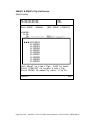
4040CL & 2044CL Clip List Screen
(Not to scale)
TM 00:00:00:00
PLAY MODE:
NORMAL
LOADED:
CLIP:
IN: --:--:--:-OUT: --:--:--:--
VTR1
(REC MODE: LOCKOUT)
DUR:--:--:--:-SPEED: +0.00
►►►CLIP0001
CLIP0002
CLIP0003
CLIP0004
CLIP0005
CLIP0006
CLIP0007
CLIP0008
CLIP0009
CLIP0010
Turn Wheel to view clips, LOAD to Load.
Press [CREATE] to Create a new clip.
Press ENTER to manually enter clip ID.
CREATE
Page 26 of 29
ESC
4040CL-L, 300 Clip Fast Access System, Louth Protocol, PBIO Option
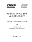
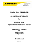
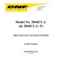
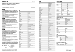
XXVII. KEY LAYOUT
4040CL-L, 300 Clip Fast Access System, Louth Protocol, PBIO Option
Page 27 of 29
XXVIII. DNF CONTROLS LIMITED WARRANTY
DNF Controls warrants its product to be free from defects in material and
workmanship for a period of one (1) year from the date of sale to the original
purchaser from DNF Controls.
In order to enforce the rights under this warranty, the customer must first contact
DNF’s Customer Support Department to afford the opportunity of identifying and
fixing the problem without sending the unit in for repair. If DNF’s Customer Support
Department cannot fix the problem, the customer will be issued a Returned
Merchandise Authorization number (RMA). The customer will then ship the defective
product prepaid to DNF Controls with the RMA number clearly indicated on the
customer’s shipping document. The merchandise is to be shipped to:
DNF Controls
12843 Foothill Blvd., Suite D
Sylmar, CA 91342
USA
Failure to obtain a proper RMA number prior to returning the product may result in
the return not being accepted, or in a charge for the required repair.
DNF Controls, at its option, will repair or replace the defective unit. DNF Controls will
return the unit prepaid to the customer. The method of shipment is at the discretion
of DNF Controls, principally UPS Ground for shipments within the United States of
America. Shipments to international customers will be sent via air. Should a
customer require the product to be returned in a more expeditious manner, the
return shipment will be billed to their freight account.
This warranty will be considered null and void if accident, misuse, abuse, improper
line voltage, fire, water, lightning or other acts of God damaged the product. All
repair parts are to be supplied by DNF Controls, either directly or through its
authorized dealer network. Similarly, any repair work not performed by either DNF
Controls or its authorized dealer may void the warranty.
After the warranty period has expired, DNF Controls offers repair services at prices
listed in the DNF Controls Price List. DNF Controls reserves the right to refuse repair
of any unit outside the warranty period that is deemed non-repairable.
DNF Controls shall not be liable for direct, indirect, incidental, consequential or other
types of damage resulting from the use of the product.
###
Page 28 of 29
4040CL-L, 300 Clip Fast Access System, Louth Protocol, PBIO Option
4040CL-L, 300 Clip Fast Access System, Louth Protocol, PBIO Option
Page 29 of 29