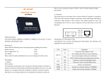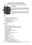
1
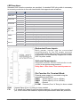
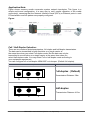
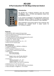
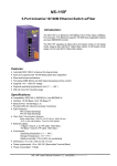
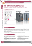
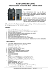
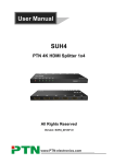
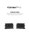
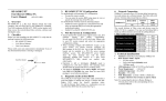
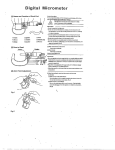
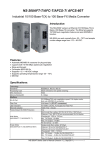
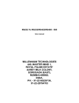
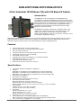
NSM-205FT/NSM-205FC/NSM-205FCS
4-Port Industrial 10/100 Base-T(X) with 100 Base-FX Switch
Introduction:
The NSM-205Fx is an unmanaged 4-Port Industrial Ethernet
(10/100Base-TX) witch Fiber (100Base-FX) Switch that secures data
transmission by using fiber optic transmission to provide immunity from
EMI/RFI interference. It is used Ethernet for transmitting a signal up to
2 Km (6,600 ft), and is the perfect solution for applications where
transmission must be protected from electrical exposure, surges,
lightning or chemical corrosion.
The NSM-205Fx operates at either half or full duplex mode. In full
duplex mode, range is 2km with 62.5/ 125μm fiber cables; in half
duplex mode, range is 412m with 62.5/ 125μm fiber cables.
Single mode fiber cables:8.3/125, 8.7/125, 9/125 or 10/125 μm; 15 km
for full duplex. (NSM-205FCS Only).
NSM-205Fx provides two power inputs that can be connected simultaneously to live DC power sources. If one of the
power inputs fails, the other live source acts as a backup to automatically support the NSM-205Fx's power needs.
NSM-205 contains "soft start" function with overload protection, high-low voltage protection.
Features:
•
•
•
•
•
•
•
•
Automatic MDI / MDI-X crossover for plug-and-play
Each port supports both 10/100 Mbps speed auto negotiation
Store-and-forward architecture
Full duplex IEEE 802.3x and half duplex backpressure flow control
3.2Gbps high performance memory bandwidth
Frame buffer memory:512 Kbit
Integrated look-up engine with dedicated 1 K unicast MAC addresses.
•
DIN rail mount and Screw hole for wall mounting kit.
Redundant Power Inputs +10 ~ +30V DC
Power failure alarm by relay output
Specifications:
•
•
•
•
•
•
•
•
•
•
•
Compatibility: IEEE 802.3, IEEE802.3u, IEEE802.3x
Interface:
NSM-205FT: 10/100 Base-T(X) and 100 Base-FX(ST Connector; Multi-mode)
NSM-205FC: 10/100 Base-T(X) and 100 Base-FX(SC Connector; Multi-mode)
NSM-205FCS: 10/100 Base-T(X) and 100 Base-FX(SC Connector; Single-mode)
Ethernet Port: 10/100 Mbps x 4
Fiber Optic Port: 100 Mbps x 1
Provides LEDs for network and power monitoring
Fiber Optic Transmission distance:
Multi mode fiber:50/125, 62.5/125 or 100/140 μm
Multi mode fiber,412 m for half duplex, 2 km for full duplex
Single mode fiber cables:8.3/125, 8.7/125, 9/125 or 10/125 μm; 15 km for full duplex.
Ethernet Cables:
10 Base-T (Cat.3, 4,5 UTP cable; 100m Max.)
100 Base-TX (Cat.5 UTP cable; 100m Max.)
Environment:
Operating Temperature: 0 °C~ +70°C
Storage Temperature: -20 ~ +85°C
Relative Humidity: 10% to 90% non-condensing
Dimensions: 73 x 110 x 102 mm (W x H x D)
Power requirements: +10 to 30V DC (Removable Terminal Block)
Alarm Contact: One relay output with current carrying capacity of 2A @ 30 VDC
Power consumption: 0.14A@24Vdc (+/- 5%, arrowed)
NSM-205Fx User’s Manual (Version 1.0, Sep/2006) --------------- 1
LED functions:
Standard RJ45 female connectors are provided. A standard RJ45 plug cable is necessary
to connect your device to the unit since switch that supports auto crossover.
LED
Color
PWR_OK
Full for P0
Link for P0
Ethernet
Port
(P1 ~ P4)
PWR2
PWR1
FAULT
Description
Red On
Core Power is OK
Red Off
Core Power is Off
Yellow On
Full Duplex
Yellow Off
Half Duplex
Green On
Link/Act
Green Off
Not Networking
Yellow On
Link/Act
Yellow Off
Not Networking
Green On
Link to 100 Mbps
Green Off
Link to 10 Mbps
Green On
Power is being supplied to power input PWR2
Green Off
Power is not being supplied to power input PWR2
Yellow On
Power is being supplied to power input PWR1
Yellow Off
Power is not being supplied to power input PWR1
Red On
Power is not being supplied to power input PWR1 and PWR2
Red Off
Power is being supplied to power input PWR1 and PWR2
Redundant Power Inputs:
Both power inputs can be connected
simultaneously to live DC power sources.
If one power source fails, the other live source acts
as a backup, and automatically supplies all of NSM205Fx’s power needs.
Soft start Power Inputs:
Integrated “soft-start” function that limits the in-rush
current to the device being powered.
Delay time + Rise time = 2 second at power on.
Pin Function For Terminal Block:
External power supply is connected using the
removable terminal block:
PWR1 : Power input 1 (+10 to +30Vdc)
PWR2 : Power input 2 (+10 to +30Vdc)
GND
: Ground
R.COM : Common(Form "A” Relay) for Alarm contact.
R.NO
F.G.
: Normal Open (Form "A” Relay) for Alarm contact.
:F.G. stands for Frame Ground (protective ground). It is optional. If you use this
pin, it can reduce EMI radiation; improve EMI performance and ESD protection.
NSM-205Fx User’s Manual (Version 1.0, Sep/2006) --------------- 2
Application Note:
Figure shows common media conversion system network topologies. This figure is a
simple end-to-end configuration; it is easy way to verify proper operation of the media
converter(s), assuming that the Network Interface Cards (NIC’s) or Ethernet ports in each
PC/workstation end link partner are properly configured.
Figure:
Full / Half-Duplex Selection:
There are two modes of data transmissions, full-duplex and half-duplex transmission.
The data can be transmitted in both directions on a single carrier at
the same time when you select Full-duplex mode. But the data can only be
transmitted in one direction on a single carrier at the same time when you
select Half-duplex mode. You may select Full or half-duplex mode according to
your equipment requirement.
You can configure full or half-duplex NSM-205Fx via Jumper. (Default: full-duplex).
JP1 Jumper
Description
Full-duplex ( Default)
Transmission Distance: 2Km
3
2
1
Half-duplex
Transmission Distance: 412m
3
2
1
NSM-205Fx User’s Manual (Version 1.0, Sep/2006) --------------- 3
Block Diagram:
Dimensions:
110.02mm
72.58mm
1mm
102.0
NSM-205Fx User’s Manual (Version 1.0, Sep/2006) --------------- 4