1
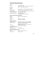
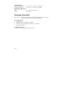
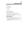
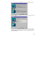
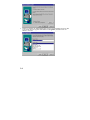
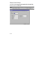
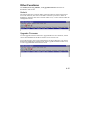
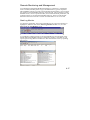
1 NPort 6110 Modbus/TCP to Serial Communication Gateway User’s Manual Fourth Edition, November 2006 Moxa Technologies Co., Ltd. Tel: Fax: Web: +886-2-8919-1230 +886-2-8919-1231 www.moxa.com MOXA Technical Support Worldwide: [email protected] The Americas: [email protected] 2 NPort 6110 Modbus/TCP to Serial Communication Gateway The software described in this manual is furnished under a license agreement and may be used only in accordance with the terms of that agreement. Copyright Notice Copyright © 2006 Moxa Technologies Co., Ltd. All rights reserved. Reproduction without permission is prohibited. Trademarks MOXA is a registered trademark of The Moxa Group. All other trademarks or registered marks in this manual belong to their respective manufacturers. Disclaimer Information in this document is subject to change without notice and does not represent a commitment on the part of Moxa. Moxa provides this document “as is,” without warranty of any kind, either expressed or implied, including, but not limited to, the particular purpose. Moxa reserves the right to make improvements and/or changes to this manual or the product(s) and/or program(s) described herein at any time. Information provided in this manual is intended to be accurate and reliable. However, Moxa Technologies assumes no responsibility for its use, or for any infringements on the rights of fourth parties which may result from its use. This manual could include unintentional technical or typographical errors. Changes are periodically made to the information herein, with the changes incorporated into new editions of the publication. MOXA Internet Services Customer satisfaction is our number one concern. To ensure that customers receive the full benefit of our products, Moxa Internet Services has been set up to provide technical support, driver updates, product information, and user’s manual updates. The following services are provided: E-mail for technical support Worldwide: The Americas: [email protected] [email protected] World Wide Web (WWW) site for product information address: or http://www.moxa.com http://www.moxa.com.tw Table of Contents 1. Introduction....................................................................................... 1-1 Overview....................................................................................... 1-1 Features........................................................................................ 1-2 Product Specifications .................................................................. 1-3 Package Checklist ........................................................................ 1-4 Front/Top/Rear/Bottom Panel Views ............................................ 1-5 2. Getting Started.................................................................................. 2-1 Power Connection ........................................................................ 2-1 Serial Installation .......................................................................... 2-1 Ethernet Installation ...................................................................... 2-2 Software Installation ..................................................................... 2-2 Housing......................................................................................... 2-7 DIN-Rail................................................................................. 2-7 Wall Mount ............................................................................ 2-8 3. Typical Modbus Applications .......................................................... 3-1 Serial master device talks to serial slave devices over the Internet .............................................................. 3-1 Ethernet master devices talk to multiple serial slave devices....................................................................... 3-2 Serial master devices talk to multiple Ethernet slave devices ................................................................. 3-3 4. Configuring Modbus Gateway ........................................................ 4-1 Starting Modbus Gateway Configurator........................................ 4-2 Searching for NPort 6110 ............................................................. 4-3 Broadcast Search.................................................................. 4-3 Specify by IP Address ........................................................... 4-3 Modify Configuration..................................................................... 4-4 Network Settings ................................................................... 4-5 Modbus Settings ................................................................... 4-6 Advanced Modbus Settings .................................................. 4-9 Modbus Serial Settings ....................................................... 4-12 Password ............................................................................ 4-14 Other Functions .......................................................................... 4-15 Unlock ................................................................................. 4-15 Upgrade Firmware .............................................................. 4-15 Remote Monitoring and Management................................. 4-17 5. Troubleshooting ............................................................................... 5-1 6. Pin Assignments............................................................................... 6-1 A. Declaration of Conformity.............................................................. A-1 B. Problem Report Form..................................................................... B-1 1 1. Introduction Welcome to Moxa NPort 6110 Modbus/TCP to Serial Communication Gateway, an easy-to-use Ethernet to RS-232/422/485 Modbus Gateway. This chapter is an introduction to NPort 6110 and includes the following sections: T Overview T Features T Product Specifications T Package Checklist T Front/Top/Rear/Bottom Panel Views Overview Moxa NPort 6110 Modbus/TCP to Serial Communication Gateway provides users with many excellent benefits, including: y Seamless integration of Ethernet and serial Modbus devices y Powerful operation modes for versatile Modbus applications y Windows utility for easy setup and traffic monitoring Each of these benefits is explained in more detail below. Seamless integration of Ethernet and serial Modbus devices Modbus is one of the most popular automation protocols in the world. Modbus protocol supports traditional RS-232/422/485 devices and newly developed Ethernet devices. Many industrial devices, such as PLCs, DCSs, HMIs, instruments, and meters, use Modbus as their communication standard. However, the Modbus protocols that run over serial and Ethernet are so different that a communication gateway is needed as a bridge for integration. NPort 6110 supports one Ethernet and one software selectable RS-232/422/485 1-1 port that can connect to many types of Modbus device. By translating Modbus/TCP (Ethernet) and Modbus/ASCII/RTU (Serial) protocols, a PLC with Ethernet can use the RS-232/485 interface to seamlessly communicate with instruments. Powerful operation modes for versatile Modbus applications For Modbus protocol conversions, it is necessary to define a Master and Slave device, but unlike other Modbus Gateways, NPort 6110 allows users to configure Master/Slave for both the Ethernet and serial sides. Extra address mapping and exception parameters are provided to ensure that most situations can be handled. Windows utility for easy setup and traffic monitoring NPort 6110 is powerful yet very easy to use. An intuitive Windows utility automatically searches for all available NPort 6110 units on the LAN. Traffic Monitoring within the utility helps you troubleshoot any Modbus communication problem, such as connection status check, or address translation error check. Features T Integration of Modbus serial and Modbus Ethernet devices T Supports connecting a Modbus/TCP Master device to up to 31 Modbus/ASCII/RTU slave devices T Supports connecting a Modbus/ASCII/RTU master device to up to 12 Modbus/TCP slave devices T Easy-to-use Windows utility for configuration over Ethernet T 10/100M fast Ethernet with automatic IP setting (DHCP) T One software selectable RS-232/485/422 interface T High speed serial interface—up to 230.4 Kbps 1-2 Product Specifications LAN Ethernet Protection Serial Interface RS-232 Signals RS-422 Signals RS-485 2-wire Signals Serial Line Protections RS-485 Data Direction 10/100 Mbps, RJ45 Auto crossover (NPort 6110 version 2.3 and above) Built-in 1.5 KV magnetic isolation RJ-232/422/485 x 1, DB9 (M), software selectable TxD, RxD, RTS, CTS, DTR, DSR, DCD, GND Tx+, Tx-, Rx+, Rx-, RTS+, RTS-, CTS+, CTS-, GND Data+(A), Data-(B), GND 15 KV ESD for all signals Patented ADDC™ (Automatic Data Direction Control) Serial Communication Parameters Parity None, Even, Odd, Mark, Space Data Bits 7, 8 Stop Bit 1, 2 Flow Control RTS/CTS, XON/XOFF Speed 1200 bps to 230.4 Kbps Software Features Internet Protocols Modbus Protocols Utilities Configuration DHCP, BootP, TCP, UDP, IP, ICMP, ARP Modbus/TCP, Modbus/ASCII, Modbus/RTU, Master/Slave modes supported Modbus Gateway Configurator for Windows 95/98/Me/NT/2000/XP Windows utility via Ethernet Power Requirements Power Input 9 to 30 VDC Power Consumption 300 mA at 12V (max.) Mechanical Specifications Material Aluminum sheet metal (1 mm) Gross Weight 0.88 kg (1.94 lb) 1-3 Environmental Operating Temperature Storage Temperature 0 to 55°C (32 to 131°F), 5 to 95% RH -20 to 85°C (-4 to 185°F), 95% RH Regulatory Approvals EMC FCC Class B, CE Class B Safety CUL, TÜV Package Checklist NPort 6110 Modbus/TCP to Serial Communication Gateway with 100-240 VAC power adaptor (US, Euro plugs included) All models include: y NPort 6110 y Software and documentation CD-ROM y 100-240 VAC power adapter, US plug, 12V, 400 mA y Euro plug included Optional Accessories: y DK-35A DIN-Rail Mounting Kit (35 mm) 1-4 Front/Top/Rear/Bottom Panel Views RESET 9-30V 10/100M Ethernet 6 (0.24") PWR 4 (0.16") Link 21.3 (0.8") 25 (0.98") 6110 Modbus/TCP to Serial Communication Gateway 12.5 (0.49") 100.4 (3.95") Ready 7 (0.28") RS-232/422/485 22.0 (0.87") 42.3 (1.67") unit = mm (inch) 67 (2.64") 78 (3.07") 90.2 (3.55") 1-5 2 2. Getting Started This chapter includes: T Power Connection T Serial Installation T Ethernet Installation T Software Installation T Housing ¾ DIN-Rail ¾ Wall Mount Power Connection Take the following steps to connect NPort 6110’s power adapter. 1. Plug the power adapter’s DC plug into NPort 6110’s DC-IN jack. 2. Plug the power adapter into an electrical outlet. Note that there is no on/off switch. NPort 6110 automatically turns on when plugged into the outlet, and the red PWR light on NPort 6110’s top panel will glow to indicate that it is receiving power. Serial Installation NPort 6110 has one male DB9 serial port on the back panel. Depending on your serial device and serial interfaces, there are two options: 1. You may use a DB9 to DB9 cable to connect your serial device to NPort 6110. Plug one end of the cable into the port on the back panel of NPort 6110 and plug the other end into your serial device’s serial port. 2. Refer to Chapter 8 for details of NPort 6110’s DB9 pinouts to make your own serial interface cable. 2-1 Ethernet Installation There are two ways to use the 10/100BaseT Ethernet jack located on NPort 6110’s front panel: 1. For most applications using NPort 6110, you will simply plug one end of an Ethernet cable into NPort 6110’s 100BaseT jack, and plug the other end into an Ethernet hub/switch connected to your network. In this case, use a regular straight-through Ethernet cable. 2. When configuring NPort 6110, you may connect NPort 6110 directly to your computer’s Ethernet connector. NPort 6110 versions 2.3 and above include automatic crossover, so a crossover cable is not required. For previous versions, you will need to use a crossover Ethernet cable when connecting the server directly to your computer.. The amber Link light will flicker when NPort 6110 is properly connected to a live Ethernet connection. Software Installation Follow the instructions given below to install Modbus Gateway Configurator, the utility that allows you to configure and monitor multiple NPort 6110 units over the network. 1. Insert the software CD-ROM that came with NPort 6110 into the CD-ROM drive, and then double click on the Setup.exe icon that installs the NPort Modbus Gateway Utility. 2-2 2. You will be greeted by the Welcome window. Click on Next to continue. 3. Enter your Name and Company name in the spaces provided, and then click on Next to continue. 4. When the Choose Destination Location window appears, click on Next to continue. If you would like to use a Destination Directory different than the one displayed, first click on Browse… to locate your folder of choice, and then click on Browse. 2-3 5. If desired, modify the highlighted name in the Program Folders text box (this is the name that will appear under Start Æ Programs) and then click on Next to continue. 2-4 6. Click on Next to start copying the software files. 7. Wait patiently while the files are being copied. The procedure should only take a few seconds. 8. The NPort Modbus Gateway Utility folder will open showing the Modbus Gateway Configurator icon. 2-5 9. You may also view this program shortcut by clicking on Start Æ Programs Æ NPort Modbus Gateway Utility Æ Modbus Gateway Configurator, as shown below. 2-6 Housing DIN-Rail For many industrial applications, you will find it convenient to use the DIN-Rail attachments, as shown below. STEP 1: Use 2 screws per ear to attach DIN-Rail mounts to each of NPort 6110’s two ears. ⇒ STEP 2: Insert the top of the DIN-Rail STEP 3: Push the bottom of NPort into the top slot of the 6110 so that the bottom of the DIN-Rail mount. DIN-Rail snaps into DIN-Rail mount’s bottom slot. NOTE: The DIN-Rail mounting kit is an optional accessory. To remove NPort 6110 from the DIN-Rail, simply reverse Steps 2 and 3 above. Grasp the bottom of the NPort 6110 unit with both hands, and then use your fingers to pull down slightly on the bottom slot of the DIN-Rail mounts to release the bottom of the DIN-Rail from the DIN-Rail mount. 2-7 Wall Mount For many industrial applications, you will find it convenient to mount NPort 6110 on the wall, using two screws, as indicated below. STEP 1: Screw two screws, separated by 7.8 cm, into the wall. The heads of the screws should be no greater than 6.5 mm in diameter, and the shafts should be no greater than 3 mm in diameter. Do not screw the screws in all the way—leave a space of about 2 mm to allow room for sliding the NPort 6110 unit’s ears between the wall and the screws. 6.5 mm 7.8 cm STEP 2: Insert the two screw heads through the large parts of the keyhole shaped apertures, and then slide NPort 6110 downwards, as indicated. RESET 9-30V STEP 3: For added stability, tighten the two screws. 10/100M Ethernet PWR RESET 9-30V Link Ready 10/100M Ethernet PWR Link Ready 6110 Modbus/TCP to Serial Communication Gateway 6110 Modbus/TCP to Serial Communication Gateway RS-232/422/485 RS-232/422/485 To remove NPort Express from the wall mount, simply reverse Steps 2 and 3. 2-8 3 3. Typical Modbus Applications In this chapter, we introduce three typical Modbus applications. Serial master device talks to serial slave devices over the Internet Let traditional Modbus serial devices talk over the Internet… Many traditional serial Modbus devices can talk over RS-485, but the RS-485 network limits the maximum number of Modbus devices to 32, provided the transmission distance does not exceed 1.2 km. By using Modbus Gateway, you can link all Serial Modbus devices over an Ethernet network. Modbus Gateways can be installed in the same control network, extending the coverage of a single Modbus network as far as a TCP/IP network can reach. NPort 6110 Modbus/RTU Master device RS-232 Ethernet NPort 6110 RS-232 NPort 6110 RS-485 NPort 6110 RS-485 Modbus/RTU Slave devices Flow meter Drives Loop controller Power measurement PLC DCS 3-1 Ethernet master devices talk to multiple serial slave devices Connect all Modbus devices over the Ethernet network… Most host computers and newly developed PLCs support the Ethernet interface and run Modbus/TCP. NPort 6110 Modbus Gateway is needed to link discrete Serial Modbus Devices for data collection and control. Each NPort 6110 supports Modbus/TCP over Ethernet, which allows up to 7 connections. The software configurable serial interface supports either RS-232 or RS-422/485. In RS-232/422 modes, NPort 6110 can be connected to 1 serial device. Under RS-485 mode, NPort 6110 supports up to 31 serial devices, which is the most popular application for factory floor applications. Host Computer Modbus/TCP Master devices PLC Ethernet NPort 6110 RS-232 NPort 6110 RS-485 Modbus/RTU Modbus/ASCII Slave devices Flow meters Drives 3-2 Loop controller Power measurement (up to 31 devices) Serial master devices talk to multiple Ethernet slave devices Link the Serial Master device with Ethernet Slave devices… Many HMI (Human Machine Interface) systems use a serial interface and are required to access a discrete DCS (Data Control System). These days however, more and more DCSs support Ethernet and run under Modbus/TCP slave mode. In this case, NPort 6110 Modbus Gateway is the ideal solution to link the HMI to distributed DCSs over an Ethernet network. Up to 12 Modbus/TCP slave devices are supported by each NPort 6110. HMI RS-232 Ethernet Modbus/RTU Master devices NPort 6110 Modbus/TCPSlave devices (up to 4) DCS DCS 3-3 4 4. Configuring Modbus Gateway We discuss the following topics in this chapter: T Starting Modbus Gateway Configurator T Searching for NPort 6110 ¾ Broadcast Search ¾ Specify by IP Address T Modify Configuration ¾ Network Settings ¾ Modbus Settings ¾ Advanced Modbus Settings ¾ Modbus Serial Settings ¾ Password T Other Functions ¾ Unlock ¾ Upgrade Firmware ¾ Remote Monitoring and Management ¾ Start Log Monitor 4-1 Starting Modbus Gateway Configurator To start Modbus Gateway Configurator, click on Start Æ Programs Æ NPort Modbus Gateway Utility Æ Modbus Gateway Configurator. The Modbus Gateway Configurator window will open as shown below. 4-2 Searching for NPort 6110 There are two methods available to search the network for NPort 6110s. Broadcast Search is used to locate all NPort 6110s connected to the same LAN as the host, and Search by IP is used to locate a specific NPort 6110, particularly if it is located outside the LAN and can only be accessed by going through a router. Broadcast Search To use the Broadcast Search function, click on the Broadcast Search icon from the toolbar, or select Broadcast Search under the Locate Gateway menu. After the search is complete, information related to all NPort 6110s located on the LAN will be displayed in the Modbus Gateway Configurator window. Specify by IP Address To use the Specify by IP Address function, click on the Specify by IP Address icon from the toolbar, or select Specify by IP Address under the Locate Gateway menu. 4-3 When the Search by IP Address window opens, input the IP address of the NPort 6110 you want to search for, and then click OK. If the search is successful, information related to the NPort 6110 will be displayed in the Modbus Gateway Configurator window. NOTE If using the Search by IP Address function fails to locate the NPort 6110, one possible reason is that the IP address you entered to conduct the search is incorrect. Try retyping the IP address and then redo the search. Another possibility is that the NPort 6110 is located on the same LAN as the host, but on a different subnet. In this case, you can change the IP address and/or Netmask of the host so that it is on the same subnet as the NPort 6110. Modify Configuration To modify the configuration of an NPort 6110, first click on the row associated with the NPort 6110 whose configuration you want to modify (to highlight the row, as shown in the following figure). Next, click on the Modify Configuration toolbar icon, or select Modify Configuration under the Configuration menu. 4-4 The Configuration window opens to the Network Settings page. Refer to the following subsections to learn more about how to configure NPort 6110’s various settings. Network Settings The Network Settings page is used to configure Modbus Gateway Name, IP Address, Netmask, Default Gateway, and IP Configuration. At the top of the page you may also view the Model Name, MAC Address, and Serial Number of the NPort 6110. These three parameters are set at the factory and cannot be modified by the user. NOTE To modify a setting, first checkmark the box to the left of the setting’s name to activate the setting’s text input box. 4-5 Network Settings Value Notes Choose a name that easily Modbus Gateway Name Alphanumeric identifies the Gateway’s location, function, etc. The IP (Internet Protocol) 32-bit number, default = IP Address address identifies the server on 192.168.127.254 the TCP/IP network. 32-bit number, Identifies the server as belonging default = Netmask to a Class A, B, or C network. 255.255.255.0 Setting Default Gateway IP Configuration IP address of the router that provides network access outside the server’s LAN. 1. Choose Static IP if you are Choose from Static using a fixed IP address. IP, DHCP, BootP, or 2. Choose one of the other DHCP/BootP. options if the IP address is set dynamically. 32-bit number, default =0.0.0.0 Modbus Settings The Modbus Settings page is used to set up the Attached Serial Device type, Initial delay time, and Modbus/TCP Slave device settings. NOTE To modify the settings on this page, first checkmark the Change Modbus Settings box. The Modbus/TCP Slave device settings are only active if the attached serial device is set as one of the two Master types. Choose the Modbus protocol of the attached serial device to determine the complementary Modbus protocol for the NPort 6110 Modbus Gateway. Four different types of serial Modbus device can be used. Since the Modbus protocol is used on a Master-Slave network, there are two steps to consider before starting the configuration process. The first step is to determine which devices are Masters and which are slaves (either Ethernet or Serial device). Next, you need to determine the Modbus protocol that the serial device uses. 4-6 4-7 Modbus Settings Value Notes 1 Modbus RTU Slave Modbus ASCII Slave2 Set the Modbus type of the serial device attached to Attached Serial Device type Modbus RTU Master3 NPort 6110’s serial port. Modbus ASCII Master4 NPort Modbus Gateway provides this setting for 100 to 3276 ms; those PLCs that need a Initial delay time default = 100 ms longer time for their system to be initialized. Modbus/TCP Slave device setting IP address assigned to Valid when the attached the remote Modbus Remote Modbus Slave IP serial device is a Modbus slave device. RTU/ASCII Master. Set this value to 0 (zero) to default = 502 TCP Port No. disable the corresponding Modbus/TCP slave device. The unique Modbus ID 1 to 247 number assigned to the ID No. Range Modbus device.5 Setting Additional Information 1. When the serial Modbus device is running in Modbus/RTU Slave mode, the NPort Modbus Gateway is ready to connect automatically to Modbus/TCP Master devices. Up to 7 Modbus/TCP master devices can connect to one serial Modbus slave device. 2. Modbus ASCII Slave mode works the same as Modbus/RTU slave mode, except that the data format is Modbus/ASCII. 3. When the serial Modbus device is running in Modbus/RTU Master mode, the NPort Modbus Gateway is ready to connect automatically to Modbus/TCP slave devices. You will also need to configure the IP address for up to 12 Modbus/TCP slave devices that can be connected to over the Ethernet network. 4-8 4. Modbus ASCII Master mode works the same as Modbus/RTU Master mode, except that the data format is Modbus/ASCII. 5. When the NPort Modbus Gateway receives a command from the serial port, the ID No. range table is used identify which IP address to connect to (e.g., if ID No. = 15, then according to the table in the Modbus Settings page shown above, the command is sent to the device that has IP of 192.168.127.3. Advanced Modbus Settings The Advanced Modbus Settings page is used to set up the Auto Slave Unit ID, Character Timeout, Message Timeout, and Modbus/TCP Exception. NOTE To modify the settings on this page, you must first checkmark the Change Modbus Settings box at the top of the Modbus Settings page. 4-9 Setting Auto Slave Unit ID Character Timeout Message Timeout Modbus/TCP Exception Advanced Modbus Settings Value Notes Select Enable when Enable (Default) multiple Modbus devices are accessible at the same Disable IP address.1 This parameter is active 10 to 3000 ms when the attached serial (default = 100 ms) device is set to Modbus/RTU.2 Allows you to configure the message timeout for 10 to 3000 ms communication between (default = 1000 ms) connected Ethernet or serial Modbus devices. This parameter is active when the Modbus Gateway connects a default = Yes Modbus/TCP Master with Modbus serial slave devices.3 Additional Information 1. Modbus/TCP protocol contains a “Unit ID” field to identify multiple Modbus slave devices accessible at a single IP address. When the Modbus/TCP command contains a Unit ID, the Modbus Gateway can pass the Unit ID to Modbus serial devices. This allows you to link to multiple serial devices with a Modbus Gateway. Some PLCs assume that each IP connects to only one device. In these cases, the Unit ID can be set “0,” but you must manually assign a Unit ID (between 1 and 247) to the connected serial device. However, each Modbus Gateway can connect to only one serial device. This setting is valid when [Attached Serial Device type] is set to [Modbus RTU Slave ] or [Modbus ASCII Slave]. Enable: Uses the Unit ID in the Modbus/TCP packet. This is the default setting. Disable: Uses the predefined Unit ID instead of Modbus/TCP’s. ID: The predefined Unit ID value, ranging from 1 to 247, which is valid 4-10 when Auto Slave Unit ID is “Disabled.” 2. When the Modbus serial protocol is set to Modbus/RTU, each message packet is determined by a character timeout. An incorrect character timeout might cause a CRC checksum error. NPort Modbus Gateway allows a variable character time out setting, ranging from 10 to 3000 ms, when the attached serial device is set to Modbus/RTU. 3. This setting is in effect when the Modbus Gateway connects a Modbus/TCP Master with Modbus serial slave devices. When the Modbus Gateway can’t get a response from Modbus serial devices, the Modbus serial protocol will not respond to the master device. However, the TCP protocol has a longer waiting time, which could cause a network traffic problem for Modbus/TCP. For this reason, Modbus Gateway can automatically send a Modbus Exception Code 10 to the Modbus/TCP master device when there is no response from the Modbus serial slave devices, making overall network communication much more efficient. Yes: No: default. No Modbus/TCP exception handling. 4-11 Modbus Serial Settings The Modbus Serial Settings page is used to configure NPort 6110’s DB9 Male port. You can configure Interface Mode, Baud Rate, Parity, Data Bits, Stop Bit, Flow Control, and UART FIFO. NOTE To modify the settings on this page, you must first checkmark the Change Modbus Settings box at the top of the Modbus Settings page. 4-12 Setting Interface Mode Modbus Serial Settings Value RS-232 RS-422 Notes NPort 6110 supports 2-wire RS-485 mode. RS-485 Baud Rate Parity Data Bits Stop Bit Flow Control UART FIFO 1200 bps to 230400 bps None, Odd, Even, Space, Mark 7, 8 ASCII = 7; RTU = 8 1, 2 None, Xon/Xoff, RTS/CTS Enable, Disable 4-13 Password Use the Password page to set a password, change the password, or erase the password. NOTE To modify the settings on this page, you must first checkmark the Change Password box at the top of the Password page. To erase an existing password, leave both the New Password and Confirm Password text input boxes blank, and then click OK in the bottom right corner of the window. 4-14 Other Functions The Unlock, Start Log Monitor, and Upgrade Firmware functions are described in this section. Unlock The Unlock function is used for NPort 6110 units that are password protected. To use the function, first click on the NPort 6110 that you wish to unlock to highlight it, and then click on the Unlock toolbar icon, or select Unlock under the Configuration menu. Upgrade Firmware Use the Upgrade Firmware function to upgrade NPort 6110’s firmware, which can be downloaded from the Moxa website at www.moxa.com. To use this function, first click on the NPort 6110 whose firmware you want to download to highlight it, and then click on the Upgrade Firmware toolbar icon, or select Upgrade under the Firmware menu. 4-15 When the Open window appears, navigate to the folder that contains the NPort 6110 firmware file, and then click on the file name. Make sure the correct filename appears in the File name box, and then click on the Open button to start downloading the firmware. Once the downloading process ends, click on Close to close the Upgrade Firmware window. The Broadcast Search function will be activated automatically and search the LAN for all NPort 6110s. 4-16 Remote Monitoring and Management To troubleshoot and manage Modbus-based device connectivity, information such as TCP/IP, Modbus protocol type, and Master/Slave type are important. NPort Modbus Gateway provides a powerful function that allows you to monitor the operation of each Modbus Gateway on the Internet. The log monitor records detailed actions, such as operation modes, serial communication parameters, and TCP/IP connectivity for the NPort Modbus Gateway. These records include date/time and can be saved as a text file for maintenance or service record. Start Log Monitor To start the Log Monitor, first click on the NPort 6110 you wish to monitor to highlight it, and then click on the Start Log Monitor toolbar icon, or select Start under the Log Monitor menu. A Log Monitor window specific to the selected NPort 6110 will appear in the bottom half of the Modbus Gateway Configurator window. Note that you can open a separate Log Monitor window for other listed NPort 6110s by repeating this process. 4-17 To start capturing the operation log, press the Start Log Monitor button . The operation log appears with time stamp stating connection status for connected Modbus devices. To keep a record of this monitor session, save the log to a text file. To clear all the records, press the Log Monitor Flush button . 4-18 5 5. Troubleshooting In this chapter, we give answers to some common troubleshooting questions related to Modbus Gateway applications. 1. ID No. mismatch ID number mismatch is the most common field installation problem encountered. First, make sure the ID number of each Modbus device corresponds to the settings in the automation software on the computer. Pay attention to Modbus Gateway’s configuration to avoid ID number issues. 1.1 When [Attached Serial Device] is set to [Modbus/RTU Slave] or [Modbus/ASCII Slave], and the [Auto Slave Unit ID] is disabled, the Modbus Gateway will use a fixed ID number. Make sure the ID number of the serial device is identical to the settings in the Modbus Gateway. 1.2 When [Attached Serial Device] is set to [Modbus/RTU Master] or [Modbus/ASCII Master], the Modbus Gateway replies on [ID No. Range] to transfer the serial Modbus device command to the IP address of the correct Modbus/TCP device. The ID number in the Ethernet device and Modbus/TCP slave device setting table must match. 2. Modbus Address configuration error Basically, Modbus Gateway will not change the Modus address in the data packet of the protocol. When your automation software or device reports address error, check that the address setting on the device is correct. 3. Proper character timeout configuration for Modbus/RTU A Modbus/RTU device requires character timeout for data packet segmentation. When a CRC error occurs, you may need to increase the character timeout in Modbus Gateway. 4. HMI polling time and timeout interval issue When [Attached Serial Device] is set to [Modbus/RTU Slave] or [Modbus/ASCII Slave], each Modbus Gateway accepts up to 7 connections from Modbus/TCP master devices. However, the Ethernet speed is much higher than the Serial speed. Therefore, proper polling time and timeout interval settings are required to prevent timeout error. For a particular HMI monitoring system, the best configuration is: polling time set to 0.5 – 1.0 sec, Timeout interval 3 sec. 5-1 6 6. Pin Assignments NPort 6110 supports three serial interfaces: RS-232, RS-422, and 2-wire RS-485. In this chapter, we give the DB9 Male pinouts for each of these three interfaces. DB9 Male Pinouts Pin No. 1 2 3 4 5 6 7 8 9 RS-232 DCD RxD TxD DTR GND DSR RTS CTS --- RS-422 TxD-(A) TxD+(B) RxD+(B) RxD-(A) GND RTS-(A) RTS+(B) CTS+(B) CTS-(A) RS-485 Data-(A) Data+(B) ----GND --------- 1 2 6 3 7 4 8 5 9 6-1 A A Declaration of Conformity Manufacturer’s Name: Manufacturer’s Address: Moxa Technologies Co., Ltd. Fl.4, No.135, Lane 235, Pao-Chiao Rd., Shing Tien City, Taipei, Taiwan, R.O.C. declares that the product: Product Name: Modbus Gateway Model Number: NPort 6110 conforms to the following standards: EMC: FCC Class B EN55022:1998 class B EN61000-3-2:1995 class B EN61000-3-3:1995 EN55082-1:1997 EN61000-4-2:1995 Contact Discharge 4kV, Air Discharge 8kV EN61000-4-3:1995 EN61000-4-4:1995 AC/DC Power supply 1kV, Data/Signal lines 5kV EN61000-4-5:1995 AC/DC Line to Line 1kV, AC/DC Line to Earth 2kV EN61000-4-6:1995 EN61000-4-8:1993 3A/m at 50Hz EN61000-4-11:1994 Safety UL/CUL, TUV EN60950 A-1 B B Problem Report Form NPort 6110 Modbus Gateway Customer name: Company: Tel: Fax: Email: Date: 1. 2. 3. Moxa Product: NPort 6110 (1 RS-232/422/485 port) Interface: RS-232 RS-422 RS-485 (2-wire) Attached serial device type: Modbus/ASCII 4. 5. 6. 7. ○ Master ○ Master ○ Slave ○ Slave Modbus/RTU Serial Number: ___________ Firmware Version: ________________ Modbus Configurator Version: ________________ Problem Description: Please describe the symptoms as clearly as possible, including all error messages. Be complete, since we may need to follow your description to reproduce the symptoms. B-1 RETURN PROCEDURE For product repair, exchange, or refund, the customer must: B-2 ♦ Provide evidence of original purchase. ♦ Obtain a Product Return Agreement (PRA) from the sales representative or dealer. ♦ Fill out the Problem Report Form (PRF). Include as much detail as possible for a shorter product repair time. ♦ Carefully pack the product in an anti-static package, and send it, pre-paid, to the dealer. The PRA should be visible on the outside of the package, and include a description of the problem, along with the return address and telephone number of a technical contact.