1
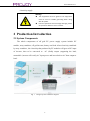
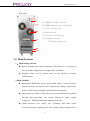
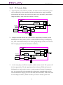
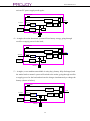
User Manual V1.1 PROMIC-3000-10000TM MPPT Solar Charger and Inverter Integrated Machine User Manual 1 User Manual V1.1 Respected customers, we appreciate for using our enterprise, ProJoy Technology Inc.’s product---GF series solar all-in –one off-grid inverter, we sincerely hope that our products can meet your needs, and you will provide more valuable advice on product performance and function. We will continue to be creative, and constantly strive for improving the quality of the products. Please read this manual carefully before using the product. Please keep this manual together with other product components material to ensure the relevant personnel can make an easy access to them. Manual content, pictures, logo, symbols and all the likes are all only owned by ProJoy Technology Inc.. Non-insiders of the Company without written authorization shall not be disclosed reproduced in whole or in part. Manual content will be constantly updated, fixed, but unavoidably it may exist some minor mistakes or slight discrepancies when compared with real things. So, please take the real one as standard, through the www.PROJOYups.com or sales channel you can download the latest version of the manual material. 2 User Manual V1.1 CONTENTS 1. 2 3 4 5 6 7 Remarks and Safety ............................................................................................................................................. 3 1.1 Product definition .................................................................................................................................... 3 1.2 Safety Precautions ................................................................................................................................... 3 Production Introduction ....................................................................................................................................... 4 2.1 System Components ................................................................................................................................ 4 2.2 Product diagram ....................................................................................................................................... 5 2.3 Appearance Instruction ............................................................................................................................ 5 2.4 Main Features .......................................................................................................................................... 6 2.5 Specifications......................................................................................................................................... 10 2.6 Working Mode Introduction ................................................................................................................... 11 2.6.1 AC Priority Mode ....................................................................................................................... 11 2.6.2 PV Priority Mode ....................................................................................................................... 13 2.6.3 Bypass Power Supply Mode ...................................................................................................... 15 2.6.4 Maintenance Mode .................................................................................................................... 15 Installation ......................................................................................................................................................... 16 3.1 Requirements of the environment .......................................................................................................... 16 3.2 Wiring connection.................................................................................................................................. 16 Operation ........................................................................................................................................................... 17 4.1 Working Mode Setting ........................................................................................................................... 17 4.2 Machine ON/OFF .................................................................................................................................. 18 4.3 ON and OFF operation after long time storage of inverter .................................................................... 18 Display ............................................................................................................................................................... 19 Maintenance....................................................................................................................................................... 21 Appendix ........................................................................................................................................................... 23 7.1 Quality Assurance .................................................................................................................................. 23 3 User Manual V1.1 1. Remarks and Safety 1.1 Product definition 如: PRO MIC 5000 TM TM:with transformer 5000:capcity is 5000W; MIC:MPPT Inverter & Solar Charger PRO:Projoy 1.2 Safety Precautions In order to keep safe in using, please comply with the followings: When under installation, user must leave at least 200mm between inverter and walls to ensure the good ventilation and cooling performance It’s normal that the temperature of the inverter surface reaches up to 550℃ when it is in operation Please do not overload the rated capacity of the inverter. Do not open the inverter’s case; otherwise it may cause a dangerous electric shock. If you want to have an internal examination please bring it to appointed service center. The internal part of the inverter will lead a electric shock or fire by short circuit ,so ,please do not place any vessel that contains liquid in it on inverter ,removing all the possible environments that may trigger shock and the likes. If the inverter is in abnormal working status, please cut down the electricity immediately and contact the agents or appointed service center. It is strictly forbidden to place and operate the inverter in following environments Please do not use liquid fire extinguishers instead of the powder one. It may trigger the danger of shock. Please put the socket near the inverter so that you can unplug it to cut off the 3 User Manual V1.1 electricity supply. Waining! The equipment must be ground. The equipment must be sure for reliable grounding when using with AC power. Incorrect operation will cause huge damage, please do operate it adhere to user’s manual. 2 Production Introduction 2.1 System Components The whole components of off grid PV power supply system include PV module ,array combiner, off grid inverter, battery and load .After electricity combined by array combiner , the electricity that produced by PV modules will goes to DC input of inverter, then to be converted to AC ,finally output ,supporting the load; meanwhile ,inverter will rectify AC input power and invert back to AC then output to load . Fig. 1 Off-grid system schematic diagram 4 User Manual V1.1 Attention! solar panels’ configuration power is related to the inverter working mode and charge current. Proposed in accordance with the views of the project unit configuration. when connecting the battery pack wire, make sure that the battery "+" and "-" properly connected, you can not reverse or be short-circuited to prevent security incidents. 2.2 Product diagram INVERTER Manual Bypass Bypass AC Input Load AC Input Rectifier Solar Controller PV Panel Inverter Filter Charger Battery 2.3 Appearance Instruction Front panel: 1 1) LCD display data screen 10 9 2 3 4 5 6 8 7 2) AC input indicator (orange one) 3) working mode indicator (green/red one) 4)bypass mode indicator (orange one) 5)Screen rolling button 6)Battery status indicator(green/red) 7)Off button“OFF” 8)Inverter Switch“ON” 9) Over load(red) 10)PV input LED(Green/Red) 5 User Manual V1.1 Rear panel: 11 12 13 11) RS485 and USB interface 12) SNMP Card interface (optional) 13)Pins setting zone 14 14)Cooling fan 15)Circuit breaker zone 15 16)Terminal blocks 17)Earth connection 16 17 2.4 Main Features 1. :Multi-setting selection System working mode can be adjusted to PV priority or AC priority on base of product configuration and light source conditions. Charging current can be chosen based on the capacity of battery configurations. 2. High reliability Independent MPPT(Max. power point tracker )Micro Control Processor System can make the best use of PV batteries by putting it on the Max. Point to realize battery charging and parameter managements. Independent Invert Micro Control Processor System enables more quickly, accurate data processing and control, high-speed online voltage regulation, SPWM modulation techniques come true. System possesses over- charge, over –discharge, load short circuit, overload protection, and unique PV anti –polarity connected protection as 6 User Manual V1.1 well ; 3. Pure sine wave technology with isolation The inverter adopt advanced SPWM adjust technology ,high –efficiency MOS, taking the advantage of isolated transformer boost technology , through LC filter to form stabilized voltage and frequency pure sine wave to support the load and deduce the noise interference to it . 4. Advanced MPPT Calculation MPPT technology is a kind of control method for Max. power point tracking , which can adjust the working point of solar batteries intelligently ,keep the battery operating at the Max. Point of I-V characteristic curve and ensure it will give a Max. Power output under different conditions .Comparing this feature to normal solar charge controllers, it will promote 20-30% on solar panel energy transform power. 5. Intelligent charging management MPPT control technology , humanized charging settable system MPPT Max .power tracks constant current 、constant voltage and interval charging ways When over charged and no PV to use, system will charge the battery with constant current automatically once AC recover. 6. LED+LCD display Intuitive LED process, state display LCD directly display product ‘s running parameters and state in all around 7. On-line working mode MPPT control system adopts PWM technology, which can withstand the highest of the open voltage of photovoltaic cells Product adopts pure online mode, double switch control principle to ensure the stability of the output voltage, frequency in any input moment, guaranteeing the reliability of the electricity. 8. Human nature alarm system 1) PV priority : 7 User Manual V1.1 When photovoltaic battery power supply is in shortage, alarm system will be issued a screaming five seconds once, automatic silence will operate in 40 seconds, and no interference to working environment at all; When the batteries run out, inverter will automatically turn off, to protect the batteries. 2) AC priority: At the initial stage of the battery (or photovoltaic battery) power supply, that will be issued five seconds once sounding alarm, after 40 seconds ,automatic silence, no interference to working environment at all; When the battery is about to run out, inverter start rush of screaming alarm again, the frequency is 0.2 seconds once a time to remind workers the batteries going to be run out and the inverter is about to shut down; When the batteries run out, inverter will automatically turn off, to protect the batteries. 9. On-line protection: Normally ,when overload reaches 110%, systems warning, in 255 seconds, if load is reduced to the rated range, system comes back to normal power supply circumstance ; Over time, the system will automatically turn to bypass power supply or shut down, the utility recovers (or manual boot) system restore to automatic power supply. Inverter overloads 120% abnormally: systems warning, in 60 seconds if load is reduced to the rated range, system comes back to normal power supply circumstance ; Over time, the system will automatically turn to bypass power supply or shut down, the utility recovers (or manual boot) system restore to automatic power supply. Inverter l overloads 120% abnormally: systems warning, in 60 seconds if load is reduced to the rated range, system comes back to normal power 8 User Manual V1.1 supply circumstance ; Over time, the system will automatically turn to bypass power supply or shut down, the utility recovers (or manual boot) system restore to automatic power supply. Short circuit protection: instant impact, short circuit, the equipment will limit output current, if more than 10 ms, system will automatically turn off. 10. Intelligent no-load shutdown (optional) In battery (or solar power supply )condition, the system will automatically detect load, if it is less than 5%, inverter will judge it as "no-load condition", in order to reduce energy loss, system will automatically turn off in no-load condition for 1 minute. 11. Automatic frequency selective When inverter accesses to AC frequency 50 Hz or 60 Hz, the system will automatically detect it , when the AC cut down , inverter output voltage and frequency will as same as utility(frequency 50 Hz or 60 Hz). 12. Intelligent communication interface (optional ) This series of inverter can be chosen with RS232 、USB or RS485、 SNMP monitoring interface together , connecting to PC communication, monitoring and supporting Windows/NT / 2000 / ME / 2003 / XP/Vista operating system to automatic file storage and inverter shutdown and Automatically detect the interruption of the boot control. utility 、the low voltage condition of inverter and the data of inverter running (LCD inverter). When utility disrupts, system starts to countdown, the action which will be done within the time are saving files, closing system and inverter in order automatically. Systems power supply time setting、 record the history material of inverter running condition 、utility state and the likes . Display system shuts down within countdown; you can set inverter with functions of self- diagnosis test, regular boot and shutdown. 13. Dry contact port(optional) The inverter provides passive dry contact: Battery low voltage, PV failure, 9 User Manual V1.1 inverter failure, bypass, overload and remote start generator dry contact signal. 2.5 Specifications Model Power Battery voltage GF300 0 3KW GF400 0 4KW Display AC mode (settable) GF800 0 8KW PV Priority/ AC Priority optional 96-200Vdc 192-400Vdc 10-40A /60A (settable) PV panels configuration (Suggestion) (Vmp) 120-142Vdc PV panels configuration (Suggestion) (Imp) ≤60A 240-284Vdc ≤40A ≤60A Max .efficiency 98% Panel Indicators LCD+LED Panel display Input voltage range 165Vac- 275Vac Input frequency range 45-65Hz(autoly transfer to battery mode beyond this range) Output voltage range 220Vac± 5% Input power factor ≥80% Max. efficiency 88%(inverter on) Over load 110% transfer to bypass in 255s,120% go to bypass in 60s, 150% go to bypass in 10s. Max. charging current Inverter output GF600 0 6KW 192Vdc Max. charging current PV GF500 0 5KW 96Vdc Working mode Input voltage range GF300 0 3KW 8A 12A Short circuit protection Electronic limited current output or turn bypass, air breaker protection Output voltage 220Vac± 5% Output frequency 50 Hz / 60Hz ± 1% Frequency self –adjusted Output power factor ≥0.8 10 User Manual V1.1 Distortion ≤ 5% Linear load PV-AC Transfer time ≤ 0Ms Max. efficiency 92% Overload 110% transfer to bypass, in 255s or shut down,120% go to bypass or shut down in 60s, 150% go to bypass or shut down in 10s. Eco mode (optional) Alarm Communic ation (optional ) Others When Load < 5%, system will turns to bypass power supply (utility) in 1min short circuit Electronic limited current output, turn the bypass or system to be automatic shutdown AC fails 4s once ,noise reduction after 40s Battery low voltage 0.2S Once over load 1 / 1S Communication interface RS232 / USB /RS485/ SNMP Dry contact PV failure、battery low-voltage、overload、bypass、inverter failure/ remote start generator dry contact signal Connection Terminal blocks Surge protection optional Magnetic Compatibility Accord with EN62040-2:2006;EA61000-3-2:2006; EA61000-3-3:2008 IP class IP20 Temperature 0℃ ~ 40℃ Humidity 10% ~ 90%(non condensing) Noise ≤ 50dB Working altitude 2000m(Every 100m increase derating 1% ) Inverter Size D*W*H(MM) 560*265*725 Packing size D*W*H(MM) 662*360*905 2.6 Working Mode Introduction 2.6.1 AC Priority Mode 1) AC Power Supply Normal: The mains power goes through rectifier, and then inverter, then after filter to user facility. At this time, the PV energy controlled by inner MPPT, only supply power to charge battery. 11 User Manual V1.1 INVERTER Manual Bypass Bypass AC Input PV Panel Load AC Input Rectifier Solar Controller Inverter Filter Charger Battery 2) The mains overload or cut-off: When the mains is out of range or outage occurs, the system will be supported quickly by transferring the power of battery and PV energy into AC power, then ensured the continuous power supply. INVERTER Manual Bypass Bypass AC Input Load AC Input Rectifier Solar Controller PV Panel Inverter Filter Charger Battery 3) The mains out of work or cut-off, and no PV: When the mains is out of work or blackout occurs, the system will be supported quickly by transferring the power of battery and PV energy into AC power, then ensured the continuous power supply. INVERTER Manual Bypass Bypass AC Input PV Panel Load AC Input Rectifier Solar Controller Inverter Charger Battery 12 Filter User Manual V1.1 2.6.2 PV Priority Mode 1) On the daytime, with sufficient sunshine, the mains normal: Solar Panels’ power will be adjusted by solar controller into the maximum power supply condition, going through the inverter for load use (the mains is on the stand by state),and to charge the battery at the same time.(shown as below); INVERTER Manual Bypass Bypass AC Input PV Panel Load AC Input Rectifier Solar Controller Inverter Filter Charger Battery 2) At night, the mains normal: the system will be supported by the battery, while discharged to a setting value (reserve a certain amount of energy for emergency use), then switch automatically to the mains, going through rectifier, inverter and filter to supply power for the load (shown as below); INVERTER Manual Bypass Bypass AC Input PV Panel Load AC Input Rectifier Inverter Solar Controller Filter Charger Battery 3) On the rainy days, insufficient sunshine, and the mains normal: The system will be first supported by PV, and supplemented by the battery. While the battery is discharged to a setting value (reserve a certain amount of energy for emergency use), the system will switch automatically to the mains, going through rectifier, inverter and filter to supply power for the load (shown as below); at the same time PV will charge the battery. When the battery is about to be full, system will 13 User Manual V1.1 activate PV power supply mode again; INVERTER Manual Bypass Bypass AC Input Load AC Input Rectifier Solar Controller PV Panel Inverter Filter Charger Battery 4) At night, the mains abnormal: system will use battery energy, going through rectifier to supply power for the load; INVERTER Manual Bypass Bypass AC Input PV Panel Load AC Input Rectifier Solar Controller Inverter Filter Charger Battery 5) At night ( or no sunshine unavailable in rainy day), battery fully discharged, and the mains back to normal: system will switch to the mains, going through rectifier to supply power for the load and activate the charger simultaneously to charge the battery (shown as below); INVERTER Manual Bypass Bypass AC Input PV Panel Load AC Input Rectifier Solar Controller Inverter Charger Battery 14 Filter User Manual V1.1 2.6.3 Bypass Power Supply Mode Load will be supported by bypass under the following four conditions : OVER LOAD; Inverter FAILURE; ON: press the ON button by 3seconds. Inverter processes soft start within 15seconds; OFF: press the OFF button by 3seconds,inverter shuts down, bypass autoly. INVERTER Manual Bypass Bypass AC Input Load AC Input Rectifier Inverter Solar Controller PV Panel Filter Charger Battery 2.6.4 Maintenance Mode When inverter needs maintaining for the inner fault, system should be switch ed into maintenance bypass model INVERTER Manual Bypass Bypass AC Input PV Panel Load AC Input Rectifier Solar Controller Inverter Charger Battery 15 Filter User Manual V1.1 3 Installation 3.1 Requirements of the environment To ensure that the machine functions well, please pay attention to the following environmental requirements: Do not put it in the moist place since the inverter is an indoor and electronic product; It’s better to put in the dry and little dust area. Indoor installed to avoid sun and rain, relative humidity (RH) 10-95% is allowed, no condensing. Keep enough space against the wall for ventilation cooling, installation and maintenance, and exit. Try no to install it near the place where people live since the machine will produce some noise. No sway for installation area. Make sure people can see the LED/LCD display easily. Environment temperature should be in a certain range(0°C ~40°C). It is well ventilated around the machine. Clean installation environment 3.2 Wiring connection According to the wiring mark at the back of the machine, the order from right to left is PV input, DC input, AC input; please refer to the following chart for AC output connection and connector bar. 16 User Manual V1.1 N L N L BAT- AC OUTPUT AC INPUT For output L 、 N connection For AC input L、N connection BAT+ DC INPUT PV- PV+ PV INPUT For battery connection For PV connection Attention! Polarity of the connecting wire should be correspondent with the marking, no reverse connect, and otherwise it would cause the damage of the machine. While Input and output connect to the earth wire, connect to sure the Earthing than 10mm. (mark) and make wire’s diameter is not less Turn the machine on after you make sure everything is right checked. 4 Operation 4.1 Working Mode Setting Before turning the machine on, ensure machine mode is set according to the requirements. Check the code dial salver, totally 3 positions, in the back of the machine. The first two are for charging current setting, the number setting and the correspondent charging current value is shown as follow. The third one is to choose AC priority mode and PV priority mode; up means AC priority, down means PV priority) . SW-1 SW-2 SW-3 Function ** ** Mains AC Priority mode ** ** PV PV Priority mode 0 0 ** PV Max. charge current 40A/60A 0 1 ** PV Max. charge current 30A 1 0 ** PV Max. charge current 20A 1 1 ** PV Max. charge current 10A 17 User Manual V1.1 4.2 Machine ON/OFF 1) According to users’ configuration and requirement, make sure the working mode (AC Priority or PV Priority). 2) When there is Mains power: Turn on the AC input switch on rear panel of inverter, inverter will start self-testing and output through bypass and will be in normal condition in 15 seconds, the user can start PC and other load at this moment 3)When PV/Battery supply power (no Mains): Turn on the switch of battery group and PV confluence box, press “ON” button on the front panel in 3 second. The system will supply power normally. 1) Daily start: Press the start button (“ON”) for 3 seconds, inverter will output normally in 15 seconds. 2) Daily shut-down: Press the shut-down button (“OFF”) for 3 seconds, inverter will turn to bypass mode if the Mains power is on. And bypass LED will be on at the moment. Otherwise the inverter will shut down. 4.3 ON and OFF operation after long time storage of inverter 1)When unused the inverter for 7 days, please push the shut-down bottom to turn off the inverter firstly, then turn off input switch/PV connection box switch/battery switch on the rear panel again. 2 )If unused above 3 months, please turn on battery and PV connection switch, let the system charge above 12 hours to keep the battery in a full power situation, to extend the life span of the battery. 4.4 . Operating steps of turning on and off maintenance switch: 1) Operating steps of turning on maintenance switch: 1) Before using maintenance switch, turn off the inverter or UPS, let the device be bypass mode or power off; 2) Take off the lock catch on “MANUALBYPASS” switch; switch on “MANUALBYPASS”; 3) Switch off the inverter or UPS “AC OUTPUT” switch, at the same time, lock the lock catch at this switch (inhibit closing this switch); 4) Start maintaining and testing the inverter or UPS. 2) Operating steps of turning off maintenance switch: 1) Let the inverter or UPS be bypass mode or power off; 2) Take off the lock catch on “AC OUTPUT” switch, switch on the inverter 18 User Manual V1.1 or UPS “AC OUTPUT”; 3) Switch off the “MANUALBYPASS” switch, at the same time, lock the lock catch at this switch (inhibit closing this switch); 4) Turn on the inverter or UPS. Attention! Products with battery detection function, you must ensure that the battery is properly connected before switch on. When you turn on the inverter, please turn on the computer and other load firstly; when you shutdown the inverter, please turn off the computer and other load firstly and then turn off the inverter. 5 Display 1) LCD screen: Name and specification of the product: Solar Inverter PROMIC 5000TM PV input status &battery status: PV Overvoltage BAT OK PV Ok BAT Undervoltage PV Undervoltage BAT Overdischarge PV Reverse!!! BAT Fault!!! AC input status and system working mode: AC OK Priority:PV Work 19 User Manual V1.1 AC Fault !!! Priority:AC Work AC Bypass Output Priority:AC Work Input Voltage status display: AC Input:220V PV Input:80.8V Output Voltage status display: AC Output:221V Frequency:49.9Hz Inv Output:219V Frequency:49.9Hz Charging status Display PV Power: 1.8KW AC Charge: OFF PV Power: 0.0KW AC Charge: ON Battery status Display Bat Voltage:218 V BatCapacity:100% Load status Display Load:100% Temperature 25℃ Load:0% Over temperature! 20 User Manual V1.1 Power status display Generated Energy : 999999.999 KWh 2) AC indicator (orange): Indicator on when there is input main power. 3)Working status indicator (Green/Red): Red indicator on when there is AC input, green indicator on when PV/battery supply the power. 4) Bypass indicator(orange):Indicator is on when the inverter is working with AC input. 5) Battery status indicator (Green/Red): Green indicator on when battery works normal, red indicator on when battery low voltage. 6) “ON” button, press 3sec to turn on inverter, and it will start to supply power after 15sec. 7) “OFF” button, press 3sec to turn off inverter (inverter will turn to bypass if had AC input, and bypass indicator on). 8) LCD scroll button, press it to scroll LCD display contents. 9) Overload indicator (red): When system overload, Indicator will on and come with buzzer alarm. 10) PV input indicator (green/red): Green indicator on when PV connect correct and voltage input normal; Red indicator on when PV connect reverse and it has input voltage 6 Maintenance 1.Preventative Maintenance Preventative maintenance to the inverter can guarantee the reliability and long-time service; do some test per month as follows: 1. Shut-down the inverter (Refer the operation steps for details); 2. Check the vents not be blocked; 3. Check whether there is much dust covering the surface; 4. Check the connection of input, output as well as batteries to see whether it is firm and the insulating barrier of cable; 6. Make sure the product not damp; 21 User Manual V1.1 7. Start inverter(ON/Off); 2.Battery Maintenance Valve Regulated Sealed Lead Acid battery is used in this system. The life time of battery will be reduced by bad operating environment, frequently discharging, and sharply temperature rising. Even battery is not in use, its performance can be gradually degraded. That is why we advise to discharge it every 3 months if there is no power-off for long time. There are maintenance steps as follows (the performance will get degraded very fast, please keep the following operations of battery maintenance in mind). 1). When the battery stay at idle status for 3 months or more than 3 months, switch on the battery and PV confluence box, charge battery up to12 hours, to keep the battery stay at full potential, to make battery life longer. 2). Make records of the load status and the total power, then shut off the PV convergence box switch, start the system, getting into the battery discharge mode until auto- off. Make records of the discharge time. Also keep the initial discharge time records for future reference. The total power of load (power consumption) is calculated in unit of “Watt” If the inverter marking just shows power capacity in “VA”, then need to multiply power factor(if no marking, it is 0.8) to calculate in unit of “Watt” If there is just Ampere value marked, then multiply rated voltage and power factor to calculate in “Watt” 3).Under normal using condition, the life time of battery is near 1-3 years. If battery temperature and discharging frequency is high, the life time will be near 0.5-1 year. 4). Along with the running time, the performance of battery is generally degraded (regarding discharging time). If the discharging time reduces to be 80% of its initial time, performance is degrading fast. So, battery maintenance should be done monthly. 5). Dust treatment: Clear the dust on battery. Check the connection cables between batteries to see whether they are loose or not, if necessary, replace the cable even the battery. Keep the battery and cable connection tight. Attention! The discharging test above is just a simple test to check the battery charging status and performance. If needing know more exact information about battery charging status, should contact with battery supplier locally. 3.Trouble shootings The inverter can offer reliability to the load. If abnormal accident occurs, suggest you go to local 22 User Manual V1.1 service center, so as to prevent more damage and unnecessary fee. When the inverter is in abnormal status, you can refer the following trouble shootings. If can’t solve problem, please get in touch with local distributor, or contract direct with our company Phenomenon Main power is normal, main power indicator is off Confirmation and Solution 1, whether Cable is loose. 2, whether fuse is burnt. In AC priority mode, system doesn’t transfer to mains mode, even mains power is ready, and switch is on, but ac LED off, and buzzer beeps Over current protection is ejected, reset over current protection In PV priority mode, PV is normal, but AC supply power PV solar power is not strong enough. The system is charging, it is a normal situation. 7 Appendix 7.1 Quality Assurance Warranty This product warranty period is 12 months, any additional provisions proof by the contract. Evidences During the warranty period, the purchase invoice and purchase date is required and the trademarks should be clearly visible on products, otherwise the right not to be assurance by the warranty. Conditions PROJOY Power Supply will repair or replace if products have any faults during the warranty period. The faulty products need to return to PROJOY Power Supply Customers expected give PROJOY Power Supply to have a reasonable amount of time for repair the faulty equipment When the following occurs, our company reserves the right not to conduct the quality assurance: The Whole Machine, components already exceed the warranty for free Transportation damage 23 User Manual V1.1 Incorrect installation, modification or use Beyond the very harsh environment to run described in this manual Machine’s fault and damage caused by not PROJOY professional’s installation, repair, alteration or demolition Mechanical failure or damage caused by the use of not PROJOY components or software Anything beyond the range of installation and use of relevant international standards. Damage caused by unnatural and non-normal environment Customers requires for maintenance service due to the product failure caused by above, PROJOY will provide the maintenance service after determine the damage If the product size and parameters are changed, to our latest material shall prevail without prior notice 24 User Manual V1.1 ProJoy Technology Inc. Tel.: 021-6806-0856 Email: [email protected] Web: www.projoy-solar.com 25