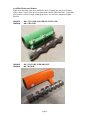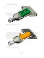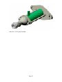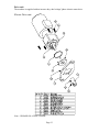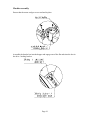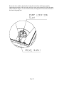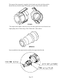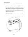
1
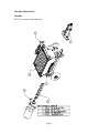
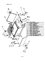
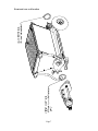
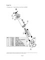
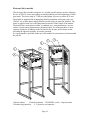
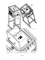
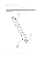
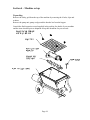
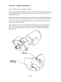
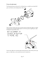
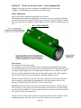
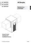
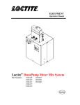
P-25 User Manual
Electric
60010051
60010083
60010097
60010111
P-25 E COMPLETE
P-25 FULL ASSY-3PHASE
P-25 FULL ASSY-480V-3PHASE-D8-1.5
P-25-E-LOHP COMPLETE
Revision 7 – 07/15/09
620 County Road 4841. Haslet, TX 76052
Ph 817.439.1108 Fax 817.439.0633
www.machine-technologies.com
Dear Customer,
Before starting this machine please complete the following;
Machine Date of purchase…………………………………..
Machine serial number………………………………………
Please read the following information contained within this manual and fully familiarize
yourself with the equipment.
Page 1
Contents
Page
Section 1 - General Safety information........................................................................... 3
Danger............................................................................................................................. 3
Section 2 - Machine Description ...................................................................................... 4
Function.......................................................................................................................... 4
Machine illustrations..................................................................................................... 5
Machine ....................................................................................................................... 5
Hopper unit................................................................................................................. 6
Front and rear seal location ...................................................................................... 7
Pump Unit ................................................................................................................... 8
Available Rotors and Stators .................................................................................... 9
Drive unit .................................................................................................................. 13
Electronic Drive module .......................................................................................... 14
Drive Shaft with bridge breakers ........................................................................... 16
Section 3 – Transportation and positioning ................................................................. 17
Section 4 – Machine set up ............................................................................................. 18
Unpacking .................................................................................................................... 18
Machine assembly........................................................................................................ 19
Electrical connections .............................................................................................. 23
Section 5 – Machine operation / speed setting.............................................................. 25
General notes for operation ........................................................................................ 25
Section 6 – Simple maintenance..................................................................................... 26
Front seal replacement................................................................................................ 27
Section 7 – Notes on wear of rotor / stator pump unit................................................ 28
Stator adjustment ........................................................................................................ 28
Wear issues................................................................................................................... 28
LIMITED WARRANTY POLICY .............................................................................. 29
Page 2
Section 1 - General Safety information
Danger
Follow these instructions very carefully, in order to avoid injury to yourself or others.
Hydraulic powered machine.
Always ensure that all power to the machine has been turned off and isolated, i.e. The
hydraulic power pack must be turned off and prevented from being started before ANY
maintenance / repair work is carried out on the machine.
Electrically powered machine.
Always ensure that all power to the machine has been turned off and isolated before
ANY maintenance / repair work is carried out on the machine.
Ensure that all guards are correctly fitted before starting or attempting to operate the
machine.
Ensure that all fasteners are present and correctly fitted before attempting to start or
operate the machine.
Ensure that the pump unit is correctly fastened to the front of the hopper unit of the
machine, and free of damage before attempting to start or operate the machine.
Ensure that the hydraulic motor, the flange and the hydraulic hoses are correctly fitted
and free from damage before attempting to start or operate the machine.
The P-25 pump unit can produce high pressures, high torques and can use high voltages.
Authorized persons when using and working with this machine must take care.
Page 3
Section 2 - Machine Description
Function
The machine has a drive motor, that turns a drive shaft within a material hopper that in
turn feeds a progressive cavity rotor stator pump unit that delivers the material from the
hopper to the dispense head via a material hose / hoses.
The machine is driven by an electric motor powered by 220VAC 3 phase 50/60Hz, via
an electronic variable speed inverter supplied by two-phase 220VAC 50/60 Hz OR a 3phase supply of 220VAC or 480VAC
Both version of drives transmit their rotary action through a drive shaft equipped with
bridge breakers, which help to mix and convey the material from the hopper towards the
pump unit.
The pump unit is a progressive cavity pump unit comprising of a helical rotating “rotor”
with the rubber lined “stator”. As material is drawn / fed into the pump unit it is forced
through a series of cavities that deform, causing the material to be moved from the
hopper towards the outlet.
Once the material has reached the outlet it is guided through an output flange assembly,
into the dispense hose through to the hose outlet, where typically a spray nozzle is
attached allowing, with the assistance of an auxiliary air supply, the material to be
“sprayed” on to the substrate.
A number of different devices can be fitted to the outlet of the tube for different means of
application. For details of these different devices please contact your supplier of
Machine-Technologies equipment or Machine-Technologies directly.
Page 4
Machine illustrations
Machine
D8-1.5 rotor stator pump illustrated.
Page 5
Hopper unit
Page 6
Front and rear seal location
Page 7
Pump Unit
“D” pump series – Typical delivery 106 ft³/hr @ 400 RPM
**Outputs are theoretical and typically 25% higher than seen in practice. Outputs are also subject to material type, moisture levels,
application method and as such testing should be performed to establish suitability.
Page 8
Available Rotors and Stators
Other rotor and stator units are available for the P-25 pump unit, which will simply
replace items 1 and 2 in the previous illustration with the following (D8-1.5 repeated),
giving either a reduced output with high pressure, or even lower output and higher
pressure.
30000039
30000040
D8-1.5 STATOR-ADJ-GREEN-INTCLAMP
D8-1.5 ROTOR
30000041
30000042
D6-3 STATOR-FIXED-ORANGE
D6-3 ROTOR
Page 9
30000043
30000044
D4-3 STATOR-FIXED-GREEN
D4-3 ROTOR
Page 10
Available pump assemblies
60010004 – D8-1.5 pump assembly
60010095 – D6-3 pump assembly
Page 11
60010110 – D4-3 pump assembly
Page 12
Drive unit
The machine is supplied with an inverter duty, dual voltage 3phase electric motor drive.
Electric Drive unit
Note – GREASE ON A DAILY BASIS.
Page 13
Electronic Drive module
The electronic Drive module comprises of a variable speed frequency inverter, allowing
the use of 220VAC two or three phase (model dependent) to run the high torque 3 Phase
gear motor. The unit is rated at 7.5 HP providing plenty of power to run the P-25 unit.
The module is supplied with an input plug allowing immediate wiring into your own
220VAC two or three phase supply (Must be carried out by an approved installer). The
motor is supplied with a pre-wired plug that fits into the 3 Phase outlet of the module.
The module has a main power isolator, a combined stop / start push button, a reverse
switch, a speed control potentiometer, internal breakers, for each input phase, a large
capacity cooling fan in addition to the fan fitted to the inverter, and a remote socket,
providing the optional capability for remote operation.
A carrying handle is provided on the top of the module for convenient re-location around
the job site.
1-Mains isolator
2-Start/Stop buttons 3-FWD/REV switch 4-Speed control
5-Remote plug/connector
6- 3 ph power out connector
Page 14
7-fan filter covers
8-Two or three phase mains power inlet
Page 15
9-Inverter drive
Drive Shaft with bridge breakers
The drive shaft couples the motor drive to the pump unit, and allows one to turn the
other.
The drive is equipped with bridge breakers, which prevent “bridges” being formed
through the material in the hopper and at the same time move material towards the inlet
of the pump unit.
1 – Drive shaft
2 – Drive paddle
3 – Bridge breaker
Page 16
Section 3 – Transportation and positioning
The machine is typically manually transported around the job site using the two carrying
handles, and the wheels in a similar manner to a wheelbarrow. The handles swing
vertically down and out of the way when not in use.
If the machine is to be permanently positioned then they can be removed and stored for
later replacement.
If the machine is being transported between sites, normally the pump unit will have been
removed from the front of the machine, due to cleaning between jobs, providing access
for lifting hooks around axle on each side of the machine and from the front of the unit.
Page 17
Section 4 – Machine set up
Unpacking
Remove the safety grid from the top of the machine by removing the 4 bolts, clips and
washers.
Remove the pump unit, pump wedges and the breaker bar from the hopper.
Consult the final inspection record supplied in the packing for details of your machine
and the items checked prior to shipment. Keep this document for your records.
Page 18
Machine assembly
Ensure that the motor wedges are secured and in place.
Assemble the breaker bar into the hopper and engage one of the flat ends into the slot in
the drive / hauling bracket.
Page 19
Rotate the drive shaft by hand until the other flat end of the shaft aligns with the
approximate position of the slot in the end of the rotor in the pump unit. Slide the pump
unit towards the hopper, over the location shafts, locating the drive shaft into the end of
the slot in the pump unit.
Page 20
Ease the pump assembly into position, then assemble the two wedges into the slots.
Manipulate the pump unit and the wedges until the pump flange is within 1/8” of the
hopper flange, then drive the wedges into position until both flange faces are flush.
Note: the drive shaft will become tight between the two drive slots during static
assembly. Once the unit has been running the compressive force will be reduced or
eliminated to within working limits. During pumping the compression will be present,
during reverse the compression will be relieved.
Important
Replace the safety grid back onto the top of the hopper and secure using the 4 clips, bolts
and washers. Operation of this machinery without the grid in place is prohibited.
Page 21
The output of the pump unit is supplied with a female cam-lock style fitting which
threads directly onto the output of the pump, giving a 35mm female connection
The output is then further reduced in size to suit the typical hoses used for this lower
output pump unit to 25mm using a 25m-35mm male - male reducer.
Once assembled to the output nozzle assembly the output looks like this
Page 22
Electrical connections
1. Ensure that there are no power connections to the Electronic drive module.
2. Site the drive module with 6’ of the P-25 unit, as this is the fitted power lead
length from the electric drive motor to the connecting plug.
3. Obtain supplied connection lead for the 220VAC feed to the drive module. The
length must be such that the delivered voltage to the drive must be 220VAC, and
capable of supplying 30A on each leg / phase. Turn the breakers OFF in the box,
and remove it from the bus bar to ensure that no voltage exists on the cables.
4. Make the connection between the drive module and the main distribution box,
using the supplied electric plug and your supplied cable. Ensure that the Earth is
connected, as well as the AC phases.
5. Connect the plug to the drive module, and ensure that the drive module rotary
isolator switch is turned OFF.
6. Replace the breakers into the distribution box, onto the bus bar and turn them ON.
7. Turn the drive module isolator to ON, and listen for the cooling fan to turn on.
Page 23
A qualified individual qualified in the use of electro-mechanical equipment must conduct
the following.
Ensure that there are no persons close to the machine.
Ensure that there are no obstructions in or around the machine.
Turn the speed control knob to position 3 on the dial.
8. Press the start button and observe the machine to turn the drive shaft in reverse
and then forwards PRESS THE STOP button, within 5 seconds or damage will
result to the pump unit.
Note the unit is equipped with an initial motor reverse timer control, in which case when
in FWD direction the motor will run in reverse until the timer times out (typically 0.4
seconds), then the unit will function in the normal manner. The reverse function it to help
“break” loose the rotor within the pump unit.
When using the supplied wired remote control, the initial reverse function is eliminated.
The pump turns in a counter-clockwise direction when viewed from the motor end
of the hopper when pumping.
9. The machine is now ready for use, by trained and qualified operators.
Page 24
Section 5 – Machine operation / speed setting
The following are to be completed by trained and experienced persons, familiar with the
pumping system provided.
1. Connect a hose to the output coupler on the end of the pump unit.
2. Fill the P-25 hopper with water and a suitable lubricant (dish soap).
3. Place the discharge end of the hose, into the hopper, making sure that the end
cannot come into contact with the moving parts inside the hopper.
4. Turn on the machine in the FWD direction and observe fluid to be displaced from
the hopper through the hose and then back to the hopper, in a recirculatory
manner.
5. Using a suitable collection vessel and a stopwatch, time the volume discharged in
a given period. Convert this amount displaced into gallons / minute. Compare this
figure with your required figure and adjust the speed accordingly.
Do not run the machine with water and lubricant for more than five minutes at a time or
damage could result to the pump unit.
General notes for operation
•
•
•
•
•
•
•
•
•
•
•
•
•
Grease hauling bracket / drive auger seal daily, with water resistant, corrosion
inhibited grease via the grease cert in the motor flange.
For starting the pump, Ensure that the speed control is at minimum, and direction
control are set to forward.
Turn main power switch on.
Push start button.
Adjust speed to desired output.
Do not let hopper run dry while pump is running.
To stop machine push the stop button.
If a hose plugs while pumping, reverse direction on pump to relieve line pressure.
Never point hose towards personnel when pump is working.
When cleaning the pump, do not remove grate while pump is running. Wash out
hopper with water and let it run out of the hose. When the hopper is clean run
foam balls through hose with clean water. Do not spray water on or in control
box. Control box should be wiped down with a damp rag.
If access is required in to the hopper, disconnect power source before removing
grate. Pump can be disassembled by removing wedges, this facilitates easier
transport and final clean up.
Pump is supplied with an adjustable stator. The sleeve can be tightened to bring
working pressure back to normal range as the stator wears down. This should be
done in small increments. Over tightening the stator will cause premature wear
and heat up material.
Always check hoses and cords for wear.
The unit runs on high voltage and is capable of high pressures in the hoses.
Page 25
Section 6 – Simple maintenance
The P-25 pump unit is very simple to maintain.
By far the biggest part of maintenance of the P-25 machine is cleaning after a job. Failure
to clean properly after use will damage seals, paint, and moving parts due to material
build up causing wear.
Pay particular attention, when cleaning, to the seals between the Rotor stator flange and
the flange on the front of the hopper, to the seal between the motor mounting flange and
the rear of the hopper, to the seal around the drive / hauling bracket fixed to the drive
flange at the rear of the machine.
Ensure that the seal between the hauling bracket and the motor is greased each day or
after each clean down, with a water resistant, corrosion inhibiting, extreme pressure
grease. Grease until a small amount of grease can be seen “oozing” from around the
hauling bracket.
Page 26
Front seal replacement
The illustration shows the front seal, in a deformed state, as would be seen when full of
grease and fitted over the hauling bracket / Drive auger.
Take special note of the grease groove positions of the seal and of the adapter, in relation
to the grease hole in the plate and the grease cert. The two grooves together give a path
for the grease to get into the cavity.
Grease using a high water resistant, high corrosion protection, and extreme pressure type
grease, on a daily basis, or after each time the unit is cleaned down
Page 27
Section 7 – Notes on wear of rotor / stator pump unit
A Rotor is the metal corkscrew looking item that ROTates inside the Stator.
A Stator is the STATionary part that the rotor rotates inside.
Stator adjustment
Some of the Stators supplied are adjustable, some are not.
The adjustable units allow the tightening of some bolts, to squeeze together two flanges,
which in turn reduce the diameter of the inside of the stator, allowing a tighter fit around
the rotor giving renewed ability to produce higher pressures, similar to when the unit was
new.
D8-1.5 ILLUSTRATED
Wear issues
Dry running of a rotor-stator pump
A screw pump can only work reliably if there is adequate and appropriate lubrication.
The lubricant reduces the friction between the rotor and the stator. If this lubricating film
is damaged, high temperatures are reached and the elastomer wears within a very short
time. Even if dry running lasts only a few seconds with new parts, the effect resembles
that of a wheel spin on a car tire, dramatically affecting length of service.
The use of simple dish soap or specific water based lubricants mixed with water while
hose cleaning, or pump priming can dramatically reduce the negative effects of dry
running, and help prolong the natural life of the rotor and stator.
Please note. that rotor stator wear is directly related to the amount of work that the unit
has to perform. A low-pressure job with a smooth mix will cause less wear than a highpressure job with smooth mix. A low-pressure job with a course mix will wear more than
a low-pressure job with a smooth mix.
The life of a rotor stator combo will need to be determined on a job-by-job basis, being
dependent upon the coarseness of the mix and the amount of pressure required.
Page 28
LIMITED WARRANTY POLICY
Machine Technologies warrants each of its new machines to be free of
defects in material and workmanship under normal use and services for a
period of one (1) year from the date of delivery.
The warranty is issued ONLY to the INITIAL USER. The warranty period
begins when the product is delivered to the initial user or when first put into
service, whichever occurs first. Said warranty is void if the machine is
subject to misuse, neglect, accident or abuse.
Machine Technologies’ obligation under this warranty is limited to
correcting without charge, at its warehouse, any parts or parts thereof which
shall be returned to its warehouse, transportation/shipping prepaid and upon
Machine Technologies’ examination proves to have been originally
defective. Correction of such defects by repair or replacement shall
constitute fulfillment of all obligations to the initial user. This warranty does
not include labor or transportation charges unless specifically identified and
authorized in writing by Machine Technologies. Nor does the warranty
apply to any unit upon which repairs or unauthorized alterations have been
made.
The warranty does not apply to normal maintenance service or to normal
replacement of certain machine parts which are subject to normal wear
(including but not limited to pins, bushings, rotors, stators, hoses, spray
caps, spray nozzles, mixing shafts, shaft couplings and connectors, dosing
shafts, pump shafts, filter elements and tires).
THIS IS A LIMITED WARRANTY AND IS IN LIEU OF ANY OTHER
WARRANTIES, EXPRESSED OR IMPLIED, INCLUDING ANY
WARRANTY OF MERCHANTABILITY OF FITNESS FOR A
PARTICULAR PURPOSE. In no event shall Machine Technologies be
made liable for incidental, general or consequential damage, loss or any
expense directly or indirectly related and resulting from use or lack of use
caused by delay in delivery, parts failure, or any other causes associated with
the product use. No person, firm or corporation is authorized to assume for
Machine Technologies any other liability in connection with the sale of
Machine Technologies products.
Page 29