1
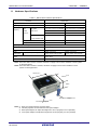
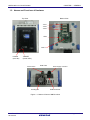
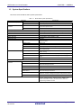
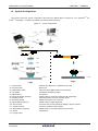
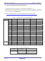
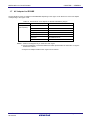
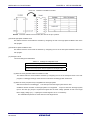
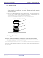
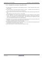
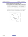
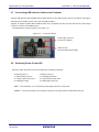
User’s Manual FF QB-RL78G13 In-Circuit Emulator User’s Manual Target Devices RL78/G12, G13 Rev.2.00 2012.3 General Precautions for Handling This Product 1. Circumstances not covered by product guarantee • If the product was disassembled, altered, or repaired by the customer • If it was dropped, broken, or given another strong shock • Use at overvoltage, use outside guaranteed temperature range, storing outside guaranteed temperature range • If power was turned on while connection to the AC adapter, USB interface cable, or target system was in an unsatisfactory state • If the cable of the AC adapter, the USB interface cable, the emulation probe, or the like was bent or pulled excessively • If an AC adapter other than the supplied product was used • If the product got wet • If this product is connected to the target system when there is a potential difference between the GND of this product and GND of the target system. • If the connectors or cables are plugged/unplugged while this product is in the power-on state. • If excessive load is applied to the connectors or sockets (As for handling, please see 2.3 Mounting and Connecting Connectors (When Using S Type Socket) or 2.4 Mounting and Connecting Connectors (When Using T Type Socket). • If a metal part of the power switch, cooling fan, or another such part comes in contact with an electrostatic charge. • If the product is used or stored in an environment where an electrostatic or electrical noise is likely to occur. 2. Safety precautions • If used for a long time, the product may become hot (50°C to 60°C). Be careful of low temperature burns and other dangers due to the product becoming hot. • Be careful of electrical shock. There is a danger of electrical shock if the product is used as described above in 1. Circumstances not covered by product guarantee. How to Use This Manual Readers This manual is intended for users who wish to perform debugging using the QBRL78G13. The readers of this manual are assumed to be familiar with the device functions and usage, and to have knowledge of debuggers. Purpose This manual is intended to give users an understanding of the basic specifications and correct usage of the QB-RL78G13. Organization This manual is divided into the following sections. • General • Setup procedure • Settings at product shipment • Cautions How to Read This Manual It is assumed that the readers of this manual have general knowledge in the fields of electrical engineering, logic circuits, and microcontrollers. This manual describes the basic setup procedures and how to set switches. To understand the overall functions and usages of the QB-RL78G13 → Read this manual in the order of the CONTENTS. The mark <R> shows major revised points. The revised points can be easily searched by copying an “<R>” in the PDF file and specifying it in the “Find what:” field. To know the manipulations, command functions, and other software-related settings of the QB-RL78G13 → See the user’s manual of the debugger (supplied with the QB-RL78G13) to be used. Conventions Note: Footnote for item marked with Note in the text Caution: Information requiring particular attention Remark: Supplementary information Numeric representation: Binary ... xxxx or xxxxB Decimal ... xxxx Hexadecimal ... xxxxH Prefix indicating power of 2 (address space, memory capacity): K (kilo): 210 = 1,024 M (mega): 220 = 1,0242 Terminology The meanings of the terms used in this manual are described in the table below. Term Meaning Target device This is the device to be emulated. This is the system to be debugged. Target system This includes the target program and the hardware provided by the user. IECUBE TM Generic name for Renesas Electronics’ high-performance / compact in-circuit emulator. Related Documents Please use the following documents in conjunction with this manual. The related documents listed below may include preliminary versions. However, preliminary versions are not marked as such. Documents Related to Development Tools (User’s Manuals) Document Name Document Number QB-RL78G13 In-Circuit Emulator This manual RL78 Family User’s Manual :Software CubeSuite+ Integrated Development Environment User’s Manual Caution R01US0015E Start R20UT0727E RL78 Design R20UT0728E RL78,78K0R Cording R20UT0729E RL78,78K0R Build R20UT0730E RL78 Debug R20UT0733E Analysis R20UT0735E Message R20UT0727E The related documents listed above are subject to change without notice. Be sure to use the latest version of each document for designing, etc. IECUBE is a registered trademark of Renesas Electronics Corporation in Japan and Germany. Windows is either registered trademarks or trademarks of Microsoft Corporation in the United States and/or other countries. PC/AT is a trademark of International Business Machines Corporation. CONTENTS CHAPTER 1 GENERAL.....................................................................................................................................7 1.1 Hardware Specifications .......................................................................................................................8 1.2 Names and Functions of Hardware ......................................................................................................9 1.3 System Specifications.........................................................................................................................11 1.4 System Configuration .........................................................................................................................12 1.5 System Configuration for Each Target Device ...................................................................................14 1.6 Package Contents ..............................................................................................................................15 1.7 AC Adapter for IECUBE......................................................................................................................19 CHAPTER 2 SETUP PROCEDURE................................................................................................................20 2.1 Software Settings................................................................................................................................21 2.2 Clock Settings .....................................................................................................................................21 2.3 Mounting and Connecting Connectors (When Using S Type Socket)................................................25 2.3.1 Mounting TC to target system ..................................................................................................25 2.3.2 Mating theTC to EA ..................................................................................................................26 2.3.3 General Precautions when Using the EA, TC ..........................................................................27 2.4 Mounting and Connecting Connectors (When Using T Type Socket)................................................28 2.4.1 Mounting NQ to target system..................................................................................................28 2.4.2 Mounting YQ to NQ ..................................................................................................................29 2.4.3 Plugging EA into YQ.................................................................................................................29 2.4.4 Precautions for handling NQ, YQ, SA, and CA ........................................................................30 2.4.5 Precautions for mounting IC using NQ and MA .......................................................................31 2.5 Connecting QB-RL78G13 to Target System ......................................................................................32 2.6 Notes on Power Supply and GND Pin Connection.............................................................................34 2.7 Connecting USB Interface Cable and AC Adapter .............................................................................35 2.8 Switching Power On and Off...............................................................................................................35 CHAPTER 3 SETTINGS AT PRODUCT SHIPMENT......................................................................................36 CHAPTER 4 CAUTIONS .................................................................................................................................37 4.1 Cautions Regarding Differences Between Target Device and Emulator ...........................................37 4.2 Debugging Note ..................................................................................................................................40 QB-RL78G13 In-Circuit Emulator CHAPTER 1 GENERAL CHAPTER 1 GENERAL The QB-RL78G13 is an in-circuit emulator for emulating the RL78/G13. Hardware and software can be debugged efficiently in the development of systems in which the RL78/G13 is used. This manual descries basic setup procedures, hardware specifications, system specifications, and how to set switches. R20UT0764EJ0200 Rev.2.00 2012.03.30 Page 7 of 44 QB-RL78G13 In-Circuit Emulator 1.1 CHAPTER 1 GENERAL Hardware Specifications Table 1-1. QB-RL78G13 Hardware Specifications Parameter Specification Target device RL78/G12 RL78/G13 Operating voltage 1.8~5.5V 1.6 to 5.5V Operating frequency Main High-speed 2.7 V VDD 5.5 V : 1 to 20 MHz 2.7 V VDD 5.5 V : 1 to 20 MHz system system clock 1.8 V VDD 2.7 V : 1 to 8 MHz High-speed 1.8 V VDD 2.7 V : 1 to 8 MHz - 1.6 V VDD 2.7 V : 1 to 4 MHz 1.8 V VDD 5.5V : 1 to 24 MHz 1.6 V VDD 5.5V : 1 to 32 MHz 1.8 V VDD 5.5 V : 15 kHz 1.6 V VDD 5.5 V : 15 kHz clock Note1 on-chip oscillator clock Low-speed system clock Note1 Subsystem clock Note2 1.6 V VDD 5.5 V : 32.768 kHz - Operating temperature range 0 to 40°C (No condensation) Storage temperature range −15 to 60°C (No condensation) External dimensions See figure below Power consumption Voltage: 1.8 to 5.5 V Current: approx. 250 mA MAX. Target system power supply Weight Approx. 400 g Host interface USB interface (1.1, 2.0) Voltage: 1.6 to 5.5 V Current: approx. 250 mA MAX Note1 Errors are within ±0.05%. However, this does not apply to errors of the oscillator or clock system on the target board. Note2 Errors are within ±0.005%. However, this does not apply to errors of the oscillator or clock system on the target board. 112mm Note1 108mm Note2 58mm Rear space Front space adapter Note3 adapter Note4 Notes 1. Does not include projection of power switch 2. Includes projection of screw that fixes rear space adapter 3. Rear space adapter can adjust the height from 30 mm (longest) to 0 mm (shortest) 4. Front space adapter can adjust the height from 20 mm (longest) to 5 mm (shortest) R20UT0764EJ0200 Rev.2.00 2012.03.30 Page 8 of 44 QB-RL78G13 In-Circuit Emulator 1.2 CHAPTER 1 GENERAL Names and Functions of Hardware Top View Bottom View TCN1 TCN2 TCN3 CN6 OSC1 POWER (Red LED) TARGET (Green LED) Power switch Cooling fan Side View Power supply connector USB connector Figure 1-1. Names of Parts of QB-RL78G13 R20UT0764EJ0200 Rev.2.00 2012.03.30 Page 9 of 44 QB-RL78G13 In-Circuit Emulator CHAPTER 1 GENERAL (1) TCN1, TCN2, TCN3 These are connectors for connecting a check pin adapter or emulation probe. (2) OSC1 This is a socket for mounting the oscillator. (3) CN6 This is a connector for the shipment inspection. It is not something that the user will need. (4) POWER (Red LED) This is an LED that shows whether the power supply of the QB-RL78G13 is switched on. LED State Lit QB-RL78G13 State Power switch ON Not lit Power switch OFF or AC adapter not connected to QB-RL78G13 Blinking Internal error occurred (Contact an Renesas Electronics sales representative or distributor) (5) TARGET (Green LED) This is an LED that shows whether the power supply of the target system is switched on. LED State Target System State Lit Target system power supply ON Not lit Target system power supply OFF or target system not connected (6) Power switch This is the power switch of the QB-RL78G13. It is OFF at shipment. (7) Cooling fun This is the cooling fun of the QB-RL78G13. It works when the power supply of the QB-RL78G13 is switched on. R20UT0764EJ0200 Rev.2.00 2012.03.30 Page 10 of 44 QB-RL78G13 In-Circuit Emulator 1.3 CHAPTER 1 GENERAL System Specifications This section shows the QB-RL78G13 system specifications. Table 1-2. QB-RL78G13 System Specifications Parameter Specification Emulation memory capacity Internal ROM 512 KB (MAX.) Internal RAM 61.75 KB (MAX.) Program execution functions Real-time execution function Go, Start from Here, Come Here, Restart, Return Out, Ignore break points and Go Non-real-time execution function Step In, Next Over, Slowmotion, Go & Go Memory manipulation Available (initialize, copy, compare) Register manipulation Available (general-purpose registers, control registers, SFRs) Disassemble function Available Local variable view Local variables Watch data view Local variables, global variables, or else Stack trace view Available Break functions Trace functions Event break Execution: 8 points Access: 8 points Software break 2000 points Pre-execution break 4 points Fail-safe break Non-map, write protect, SFR illegal access, stack overflow, or else Other Forcible break, trace full break, trace delay break, timeout break, timer overflow break Trace data types Program address, program data, access address, access data, status, time tag Trace modes Unconditional trace, section trace, qualify trace, delay trigger trace Trace functions Non-stop, full stop, full break, delay trigger stop, delay trigger break Memory capacity 128K frames Real-time RAM monitoring function All internal RAM spaces Time measurement functions Measurement clock 120 MHz Measurement objects Start through end of program execution Start event through end event Maximum measurement time Approx. 40 hours and 43 minutes Minimum resolution 8ns Number of timers for measurement Start through end of program execution: 1 Start event through end event: 2 Measurement results Execution time (start through end of execution) Maximum, minimum, average, total, pass count (between events) Other Other functions R20UT0764EJ0200 Rev.2.00 2012.03.30 Timer overflow break function, timeout break function Command functions set in the console, mapping function, event function, coverage function, snapshot function, DMM function, power-off emulation function, pin mask function, flash self programming emulation function Page 11 of 44 QB-RL78G13 In-Circuit Emulator 1.4 CHAPTER 1 GENERAL System Configuration This section shows the system configuration when using the QB-RL78G13 connected to a PC (WindowsTM PC, PC/AT TM compatible). Connection is possible even without optional products. Figure 1-2. System Configuration <1> <3> <5> <4> <2> <6> <7> <8> <8> < 12 > <9> < 13 > < 10 > < 11 > < 11 > < 14 > < 14 > T type <1> Host machine <2> Accessory Disk <3> USB interface cable <4> AC adapter <5> QB-RL78G13 <6> Check pin adapter (optional) <7> Emulation probe <8> Exchange adapter <9> Space adapter (optional) <10> YQ connector <11> Target connector <12> Mount adapter (optional) <13> Device S type : Windows PC, IBM PC/AT compatible can be used : Manual, etc. : Cable connecting QB-RL78G13 to host machine : AC adapters classified by region : This product : Adapter used for monitoring waveforms with oscilloscope : High-characteristic FPC type emulation probe : Adapter that performs pin conversion : Adapter used for height adjustment : Connector that connects exchange adapter to target connector : Connector soldered to target system : Adapter used for mounting target device into socket : Target device <14> Target system R20UT0764EJ0200 Rev.2.00 2012.03.30 Page 12 of 44 QB-RL78G13 In-Circuit Emulator CHAPTER 1 GENERAL Remarks 1. Refer to 1.6 Package Contents for the purchase forms of the above products. 2. As for handling of connectors, refer to 2.3 Mounting and Connecting Connectors (When Using S Type Socket) or 2.4 Mounting and Connecting Connectors (When Using T Type Socket). 3. The part number of <4> differs depending on the region of use. See Table 1-5 Part Numbers of AC Adapter for IECUBE Classified by Region for the part numbers. The IECUBE requires an AC adapter that must be purchased separately. 4. See Table 1-4 Common Probe and Adapter for the part numbers of <6> and <7>. 5. The combination of <8>, <9>, <10>, <11>, and <12> varies depending on the emulation device. See Table 1-3 Adapters and Connectors for Each Target Device for the combinations. To determine the T Type socket or the S Type socket, check for "T" or "S" at the end of the socket product name. Example: QB-64FB-EA-01T -> T Type QB-48NA-EA-02S -> S Type 7. Even with the T Type socket, there may not be a space adapter/YQ connector/mount adapter. In this case, the device cannot be mounted in the socket. Check Table 1-3 Adapters and Connectors for Each Target Device. 6. R20UT0764EJ0200 Rev.2.00 2012.03.30 Page 13 of 44 QB-RL78G13 In-Circuit Emulator 1.5 CHAPTER 1 GENERAL System Configuration for Each Target Device The following table lists the system configuration for each target device of the QB-RL78G13. The adapter and connector for each device, and common probe and adapter are sold separately. An exchange adapter, a YQ connector, a target connector, and an emulation probe are included, depending on the order product name. For details, refer to 1.6 Package Contents. Remark For the package drawings of the connector, adapter, and probe, refer to the following URL. http://www.renesas.com/products/tools/emulation_debugging/incircuit_emulators/iecube/rl78/index.jsp Table 1-3. Target Device RL78/G13 RL78/G12 Package Adapters and Connectors for Each Target Device Exchange Adaptor Space Adaptor YQ Connector Target Connector Mount Adaptor 20SP QB-20SP-EA-01T - - QB-20SP-NQ-01T - 24NA QB-24NA-EA-01S - - QB-24NA-TC-01S - - QB-25LA -NQ-01T - - 25LA QB-25LA-EA-01T 30SP QB-30SP-EA-01T 32NA QB-32NA-EA-02S - - QB-32NA-TC-01S - 36LA QB-36LA-EA-01T - - QB-36LA-NQ-01T - 40NA QB-40NA-EA-01S - - QB-40NA-TC-01S - 44FP QB-44FP-EA-01T QB-44FP -YS-01T QB-44FP -YQ-01T QB-44FP -NQ-01T QB-44FP -HQ-01T 48FB QB-48FB-EA-01T QB-48FB -YS-01T QB-48FB -YQ-01T QB-48FB -NQ-01T QB-48FB -HQ-01T 48NA QB-48NA-EA-01S - QB-48NA-TC-01S QB-30SP-YS-01T - QB-30SP-YQ-01T QB-30SP-NQ-01T QB-30SP-HQ-01T - 52FA QB-52FA-EA-01T QB-52FA -YS-01T QB-52FA -YQ-01T QB-52FA -NQ-01T QB-52FA -HQ-01T 64FA QB-64FA -EA-01T QB-64FA -YS-01T QB-64FA -YQ-01T QB-64FA -NQ-01T QB-64FA-HQ-01T 64FB QB-64FB-EA-01T QB-64FB -YS-01T QB-64FB -YQ-01T QB-64FB -NQ-01T QB-64FB -HQ-01T 64BG QB-64BG-EA-01T - QB-64BG-NQ-01T 80FA QB-80FA-EA-01T QB-80FA-YS-01T QB-80FA-YQ-01T QB-80FA-NQ-01T QB-80FA-HQ-01T 80FB QB-80FB-EA-01T QB-80FB-YS-01T QB-80FB-YQ-01T QB-80FB-NQ-01T QB-80FB-HQ-01T 100FA QB-100FA-EA-01T QB-100FA-YS-01T QB-100FA-YQ-01T QB-100FA-NQ-01T QB-100FA-HQ-01T 100FB QB-100FB-EA-01T QB-100FB-YS-01T QB-100FB-YQ-01T QB-100FB-NQ-01T QB-100FB-HQ-01T 128FB QB-128FB-EA-01T QB-128FB-YS-01T QB-128FB-YQ-01T QB-128FB-NQ-01T QB-128FB-HQ-01T 20SP QB-20SP-EA-04T QB-20SP-YS-01T QB-20SP-YQ-01T QB-20SPNQ-01T QB-20SP-HQ-01T 24NA QB-24NA-EA-02S 30SP QB-30SP-EA-01T - - QB-30SP-YS-01T - QB-30SP-YQ-01T QB-24NA-TC-01S QB-30SP-NQ-01T - - QB-30SP-HQ-01T Table 1-4. Common Probe and Adapter Name Part Number Target Device Check pin adapter QB-144-CA-01 RL78/G12,G13 Emulation probe QB-80-EP-01T Under 80pin of RL78/G13, RL78/G12 QB-144-EP-02S Over 100pin of RL78/G13 R20UT0764EJ0200 Rev.2.00 2012.03.30 Page 14 of 44 QB-RL78G13 In-Circuit Emulator 1.6 CHAPTER 1 GENERAL Package Contents The included products are described for each order product name. Products supplied with QB-RL78G13-ZZZ 1: QB-RL78G13 2: USB interface cable (2 meters) 3: Online user registration card (warranty card and software contract in one) 4: Accessory Disk (CD-ROM) 5: Packing list Products supplied with QB-RL78G13-T20SP 1 to 5 6: Emulation probe QB-80-EP-01T 7: Exchange adapter QB-20SP-EA-01T 8: Target connector QB-20SP-NQ-01T Products supplied with QB-RL78G13-T20SP04 1 to 5 6: Emulation probe QB-80-EP-01T 7: Exchange adapter 8: Target connector QB-20SP-NQ-01T QB-20SP-EA-04T Products supplied with QB-RL78G13-T24NA 1 to 5 6: Emulation probe QB-80-EP-01T 7: Exchange adapter QB-24NA-EA-01S 8: Target connector QB-24NA-TC-01S Products supplied with QB-RL78G13-S24NA02 1 to 5 6: Emulation probe 7: Exchange adapter QB-80-EP-01T 8: Target connector QB-24NA-TC-01S QB-24NA-EA-02S Products supplied with QB-RL78G13-T25LA 1 to 5 6: Emulation probe QB-80-EP-01T 7: Exchange adapter QB-25LA-EA-01T 8: Target connector QB-25LA-NQ-01T Products supplied with QB-RL78G13-T30SP 1 to 5 6: Emulation probe QB-80-EP-01T 7: Exchange adapter QB-30SP-EA-01T 8: YQ connector QB-30SP-YQ-01T 9: Target connector QB-30SP-NQ-01T R20UT0764EJ0200 Rev.2.00 2012.03.30 Page 15 of 44 QB-RL78G13 In-Circuit Emulator CHAPTER 1 GENERAL Products supplied with QB-RL78G13-S32NA 1 to 5 6: Emulation probe QB-80-EP-01T 7: Exchange adapter QB-32NA-EA-02S 8: Target connector QB-32NA-TC-01S Products supplied with QB-RL78G13-T36LA 1 to 5 6: Emulation probe QB-80-EP-01T 7: Exchange adapter QB-36LA-EA-01T 8: Target connector QB-36LA-NQ-01T Products supplied with QB-RL78G13- S40NA 1 to 5 6: Emulation probe QB-80-EP-01T 7: Exchange adapter QB-40NA-EA-01S 8: Target connector QB-40NA-TC-01S Products supplied with QB-RL78G13-T44FP 1 to 5 6: Emulation probe QB-80-EP-01T 7: Exchange adapter QB-44FP-EA-01T 8: YQ connector QB-44FP-YQ-01T 9: Target connector QB-44FP-NQ-01T Products supplied with QB-RL78G13-T48FB 1 to 5 6: Emulation probe QB-80-EP-01T 7: Exchange adapter QB-48FB-EA-01T 8: YQ connector QB-48FB-YQ-01T 9: Target connector QB-48FB-NQ-01T Products supplied with QB-RL78G13-S48NA 1 to 5 6: Emulation probe QB-80-EP-01T 7: Exchange adapter QB-48NA-EA-01S 8: Target connector QB-48NA-TC-01S Products supplied with QB-RL78G13-T52FA 1 to 5 6: Emulation probe QB-80-EP-01T 7: Exchange adapter QB-52FA-EA-01T 8: YQ connector QB-52FA-YQ-01T 9: Target connector QB-52FA-NQ-01T R20UT0764EJ0200 Rev.2.00 2012.03.30 Page 16 of 44 QB-RL78G13 In-Circuit Emulator CHAPTER 1 GENERAL Products supplied with QB-RL78G13-T64FA 1 to 5 6: Emulation probe QB-80-EP-01T 7: Exchange adapter QB-64FA-EA-01T 8: YQ connector QB-64FA-YQ-01T 9: Target connector QB-64FA-NQ-01T Products supplied with QB-RL78G13-T64FB 1 to 5 6: Emulation probe QB-80-EP-01T 7: Exchange adapter QB-64FB-EA-01T 8: YQ connector QB-64FB-YQ-01T 9: Target connector QB-64FB-NQ-01T Products supplied with QB-RL78G13-T64BG 1 to 5 6: Emulation probe QB-80-EP-01T 7: Exchange adapter QB-64BG-EA-01T 8: Target connector QB-64BG-NQ-01T Products supplied with QB-RL78G13-T80FA 1 to 5 6: Emulation probe QB-80-EP-01T 7: Exchange adapter QB-80FA-EA-01T 8: YQ connector QB-80FA-YQ-01T 9: Target connector QB-80FA-NQ-01T Products supplied with QB-RL78G13-T80FB 1 to 5 6: Emulation probe QB-80-EP-01T 7: Exchange adapter QB-80FB-EA-01T 8: YQ connector QB-80FB-YQ-01T 9: Target connector QB-80FB-NQ-01T Products supplied with QB-RL78G13-T100FA 1 to 5 6: Emulation probe QB-144-EP-02S 7: Exchange adapter QB-100FA-EA-02T 8: YQ connector QB-100FA-YQ-01T 9: Target connector QB-100FA-NQ-01T Products supplied with QB-RL78G13-T100FB 1 to 5 6: Emulation probe QB-144-EP-02S 7: Exchange adapter QB-100FB-EA-01T 8: YQ connector QB-100FB-YQ-01T 9: Target connector QB-100FB-NQ-01T R20UT0764EJ0200 Rev.2.00 2012.03.30 Page 17 of 44 QB-RL78G13 In-Circuit Emulator CHAPTER 1 GENERAL Products supplied with QB-RL78G13-T128FB 1 to 5 6: Emulation probe QB-144-EP-02S 7: Exchange adapter QB-128FB-EA-01T 8: YQ connector QB-128FB-YQ-01T 9: Target connector QB-128FB-NQ-01T R20UT0764EJ0200 Rev.2.00 2012.03.30 Page 18 of 44 QB-RL78G13 In-Circuit Emulator 1.7 CHAPTER 1 GENERAL AC Adapter for IECUBE The specifications of the AC adapter for IECUBE differ depending on the region of use. Be sure to use an AC adapter corresponding to the region of use. Table 1-5. Part Numbers of AC Adapter for IECUBE Classified by Region Product AC adapter (sold separately) Destination (Region)Notes 1, 2 Part NumberNote 3 Japan QB-COMMON-PW-JP USA QB-COMMON-PW-EA China QB-COMMON-PW-CN Hong Kong QB-COMMON-PW-HK South Korea QB-COMMON-PW-KR Singapore QB-COMMON-PW-SG Taiwan QB-COMMON-PW-TW Notes 1. Products are shipped only on order from each region. 2. Contact a distributor or a Renesas Electronics sales representative for information on regions other than the above. 3. Only the AC adapter usable in each region can be ordered R20UT0764EJ0200 Rev.2.00 2012.03.30 Page 19 of 44 QB-RL78G13 In-Circuit Emulator CHAPTER 2 CHAPTER 2 SETUP PROCEDURE SETUP PROCEDURE This chapter explains the QB-RL78G13 setup procedure. Setup can be completed by performing installation setup in the order in which it appears in this chapter. Perform setup along the lines of the following procedure. See 1.2 Names and Functions of Hardware for clock positions. Software settings 2.1 Software Settings. Clock settings 2.2 See Clock Settings. Mounting and connecting connectors When using the S type socket, see 2.3 Mounting and Connecting Connectors (When Using S Type Socket) When using the T type socket, see 2.4 Mounting and Connecting Connectors (When Using T Type Socket) Connecting QB-RL78G13 to target system 2.5 See Connecting QB-RL78G13 to target system. Connecting USB interface cable and AC adapter 2.7 See Connecting USB interface cable and AC adapter. Switching power on and off 2.8 See Switching power on and off. R20UT0764EJ0200 Rev.2.00 2012.03.30 Page 20 of 44 QB-RL78G13 In-Circuit Emulator 2.1 CHAPTER 2 SETUP PROCEDURE Software Settings Check the user's manual for the debugger that will be used. 2.2 Clock Settings The IECUBE clock must be set to the clock used by the target device. For details about how to set the clock, check the user's manual for the debugger that will be used. IECUBE clock settings for the clock used by the target device are shown below. Oscillation with the resonator on the target system is not supported. Therefore, the in-circuit emulator cannot emulate the oscillation operation of the clock on the target system. Table 2-1. List of clock settings Clock Used (1) High-speed system clock (X1 oscillator or External input) Clock Supply (a) When the clock generated within the emulator is used (b) When the clock (a square wave) is supplied from the target system (c) When the oscillator (OSC1) mounted onto the emulator is used (2) Internal high-speed Uses the clock internally generated from the emulator oscillation clock (3) Internal low-speed Uses the clock internally generated from the emulator oscillation clock (4) Subsystem clock (XT1 oscillator or External input) R20UT0764EJ0200 Rev.2.00 2012.03.30 (a) When the clock generated within the emulator is used (b) When the clock (a square wave) is supplied from the target system Page 21 of 44 QB-RL78G13 In-Circuit Emulator CHAPTER 2 SETUP PROCEDURE (1) High-speed system clock The clock settings are listed below. Table 2-2. Settings for High-Speed System Clock Type of Clock to Be Used OSC1 (a) When the clock generated within the emulator is used (b) When the clock (a square wave) is supplied from the target system – Note (c) When the oscillator (OSC1) mounted onto the emulator is used – Oscillator mounted Note This setting is not possible when TARGET LED is not lit. Remarks 1. Settings other than the above are prohibited. 2. Selection of (a) or (b) is possible regardless of whether the oscillator is not mounted in the OSC1socket. (a) When the clock generated within the emulator is used This method uses the clock generated inside the emulator. The oscillation frequency that will be used must be set in the debugger. For details about how to set the oscillation frequency, check the user's manual for the debugger that will be used. (b) When the clock (a square wave) is supplied from the target system The clock input from the target system is then used. To input a clock from the target system, input to the clock pin (X2) the square-wave signal with the same voltage potential as that of the target device supply voltage (VDD). Inputting the inverted signal to X1 is not necessary. The selectable frequencies are same as those of the target device. For debugger settings, check the user's manual for the debugger that will be used. Oscillation by a resonator in the target system is not supported. (c) When the oscillator (OSC1) mounted onto the emulator is used Mount an oscillator in the OSC1 socket in the emulator and then select the “Clock socket” in the debugger. The clock generated from the oscillator mounted on the emulator is used. The selectable frequencies are same as those of the target device. To modify the clock setting, the acrylic board on the bottom of the QB-RL78G13 must be removed. The acrylic board can be removed by lifting it up. For debugger settings, check the user's manual for the debugger that will be used. R20UT0764EJ0200 Rev.2.00 2012.03.30 Page 22 of 44 QB-RL78G13 In-Circuit Emulator CHAPTER 2 SETUP PROCEDURE Figure 2-1. Acrylic Board Removal Method As an oscillatorNote to be mounted in the OSC1 socket in the emulator, use the one that satisfies the following specifications. - Supply voltage: 5.0 V - Output level: CMOS Note An oscillator that uses a resonator cannot be used. Figure 2-2. Oscillator Shape Top View R20UT0764EJ0200 Rev.2.00 2012.03.30 Page 23 of 44 QB-RL78G13 In-Circuit Emulator CHAPTER 2 SETUP PROCEDURE Figure 2-3. Mapping of Oscillator to Socket Remark Insert the oscillator into the socket, take care for the pin 1 position. (2) Internal high-speed oscillation clock This method uses the clock inside the emulator by configuring the use of the high-speed oscillation clock in the user program. (3) Internal low-speed oscillation clock This method uses the clock inside the emulator by configuring the use of the low-speed oscillation clock in the user program. (4) Subsystem clock The clock settings are listed below. Table 2-3. Settings for Subsystem Clock Type of Clock to Be Used (a) When the clock generated within the emulator is used (b) When the clock (a square wave) is supplied from the target systemNote (a) When the clock generated within the emulator is used This method uses the clock inside the emulator by configuring the use of the subsystem clock in the user program. For debugger settings, check the user's manual for the debugger that will be used. (b) When the clock (a square wave) is supplied from the target system Select the “External” in the debugger. The clock input from the target system is then used. Oscillation with the resonator on the target system is not supported. To input a clock from the target system, input to the clock pin (XT2) the square-wave signal with the same voltage potential as that of the target device supply voltage (VDD). Inputting the inverted signal to XT1 is not necessary. The selectable frequencies are same as those of the target device. R20UT0764EJ0200 Rev.2.00 2012.03.30 Page 24 of 44 QB-RL78G13 In-Circuit Emulator 2.3 CHAPTER 2 SETUP PROCEDURE Mounting and Connecting Connectors (When Using S Type Socket) This section describes the methods of connecting the QB-RL78G13 and target system. Make connections with both the QB-RL78G13 and target system powered OFF. The following abbreviations are used in this section: - TC: Target connector - EA: Exchange adapter - CA: Check pin adapter 2.3.1 Mounting TC to target system (1) Apply cream solder to the foot pattern of the target system for mounting an IC (2) There is a circular protrusion (Figure2-4) in middle of the bottom of the TC. The center of this cylinder is a metallic component (metal plated) for the GND connection. In the same manner as the IC pad, the TC GND is connected to the target board GND by applying cream solder to the pad in the center of the recommended IC foot pattern and then reflow soldering. Figure 2-4. TC protrusion (3) Soldering condition of TC (a) Reflow soldering At 235°C for amaximum of 10 seconds (main heating) (b) Manual soldering insulator At 320°C for a maximum of 5 seconds (per pin) (4) Precautions on flux splatter metal If the solder flux splatters when the connector is soldered, faulty contact may occur. Be sure to cover the upper part of the connector with aluminum foil. Do not clean the connector because the flux solvent may remain inside the connector. R20UT0764EJ0200 Rev.2.00 2012.03.30 Page 25 of 44 QB-RL78G13 In-Circuit Emulator CHAPTER 2 SETUP PROCEDURE 2.3.2 Mating theTC to EA Mate the TC and EA by following the procedure below. (1) Check the orientation of pin 1, align the TC guide pin to the guide hole at the tip of the EA flexible printed circuit (FPC), and then insert it. (See Figure 2-5) (2) Check conductivity between the TC and EA at this time. (3) Solder the TC to the guide locking pad that can be seen from the FPC tip flexible guide hole using a soldering iron with a tip radius of φ1.0 mm or smaller. (Once soldered, the TC and EA cannot be removed from each other.) (4) Use extreme care so that the EA (FPC cable) does not apply stress to the TC. If the EA applies even a small amount of stress to the TC, we recommend securing the section soldered to the TC board with adhesive. Figure 2-5 Magnified guide hole view when TC and EA are mated & mating diagram. EA Tip of EA TC When the EA and TC are mated Magnified view: The guide pin can be seen when the TC and EA are mated R20UT0764EJ0200 Rev.2.00 2012.03.30 Page 26 of 44 QB-RL78G13 In-Circuit Emulator 2.3.3 CHAPTER 2 SETUP PROCEDURE General Precautions when Using the EA, TC (1) Causes of connector conductivity problems (a) When flux gets inside the connector when mounting the TC Since flux easily rises into the connector, if it gets into the connector, completely wash it out using a solvent such as alcohol. Wash it at least five or six times. If conductivity is unstable, repeatedly wash it. (b) Debris gets inside the connector If debris such as fuzz gets inside the connector, it will cause conductivity problems. Clear out the debris with a brush. (c) Precautions when using the CA When using the CA, while minor, signal propagation delay and capacitance occurs by inserting each adapter. Connect the CA to the target system and fully evaluate it before use. (2) CA The CA is an optional product for IECUBE, and can be used to measure the waveform between IECUBE and the target system. Since the pins on the CA do not correspond to the pin layout in each device, the pin header cover must be mounted according to the device to be used. For mounting methods of the pin header cover, refer to URL. http://japan.renesas.com/qb_144_ca_01 R20UT0764EJ0200 Rev.2.00 2012.03.30 Page 27 of 44 QB-RL78G13 In-Circuit Emulator 2.4 CHAPTER 2 SETUP PROCEDURE Mounting and Connecting Connectors (When Using T Type Socket) This section describes the methods of connecting the QB-RL78G13 and target system. Make connections with both the QB-RL78G13 and target system powered OFF. The following abbreviations are used in this section: - NQ: Target connector - YQ: YQ connector - EA: Exchange adapter - MA: Mount adapter - CA: Check pin adapter - SA: Space adapter 2.4.1 Mounting NQ to target system (1) Thinly apply a two-component epoxy adhesive (hardening time at least 30 minutes) to the ends of the four projections on the base of the NQ and adhere the NQ to the user board (clean the surface of the target system board using alcohol or the like). If alignment of target system pads to NQ leads is difficult, align them as in (2). (2) Align by inserting the guide pins for alignment for the NQ (NQGUIDE) through the pin holes on the top of the NQ. Accessory holes are 1.0 mm non-through holes in two or three places. (For hole positions, see the particular NQ drawing.) (3) Solder after fitting the MA to the NQ. This is to prevent troubles such as flux or solder splashing and adhering to the NQ contact pins when soldering. - Soldering conditions Caution Solder reflow 260°C 10 seconds or less Manual soldering 350°C 5 seconds or less (1 pin) Do not perform washing by flux immersion or vapor. (4) Take away the guide pins. R20UT0764EJ0200 Rev.2.00 2012.03.30 Page 28 of 44 QB-RL78G13 In-Circuit Emulator 2.4.2 CHAPTER 2 SETUP PROCEDURE Mounting YQ to NQ (1) After confirming that there are no broken or bent YQ contact pins, fit the YQ in the NQ and fasten it using the supplied YQGUIDE (for the fastening method, see the next step, (2)). If repeatedly inserting and removing, be sure to inspect the YQ pins before fitting. If pins are bent, correct them using something thin and flat such as the edge of a knife. (2) Fasten YQ to the NQ on the target system using the supplied YQGUIDE. Fasten the screws equally in the four corners using the supplied flat-blade screwdriver or a torque driver. The tightening torque of the YQGUIDE is 0.054 Nm (MAX.). Too great tightening causes bad connections. However, four screws for fitting to the NQ (M2 x 10 mm / 4 units) are included with the YQ. Figure 2-6. Mounting of EA, YQ and NQ EA YQGUIDE supplied with YQ YQ NQ TC Target system 2.4.3 Plugging EA into YQ Match the pin 1 position of the YQ or SA (corner cuts match in both) to the pin 1 position of the EA and plug in. - When plugging or unplugging, press on the NQ, YQ, and SA with a finger so that there is no force on the NQ. - When plugging or unplugging, be careful of the direction of wiggling. As a tool when unplugging, insert some kind of thin non-conductive material such as a wooden stick between the YQ (SA) and EA and wiggle while slowly unplugging. Be careful since the connector will be damaged if this is done in the wrong direction. R20UT0764EJ0200 Rev.2.00 2012.03.30 Page 29 of 44 QB-RL78G13 In-Circuit Emulator 2.4.4 CHAPTER 2 SETUP PROCEDURE Precautions for handling NQ, YQ, SA, and CA (1) When taking the NQ from the box, press down on the body and take out the sponge first. (2) Since the pins of the YQ are thin and easily bent, be careful. When inserting it in the NQ, confirm that there are no bent pins. (3) When screwing a YQ soldered to a board to the NQ, fasten the screws in four places in turn using a #0 or #1 Phillips precision screwdriver or torque driver after tentatively tightening them. Fix the torque at 0.054 Nm (MAX.). If just one place is overtightened, it may cause poor contact. Moreover, a board being connected to the YQ must have accessory holes in prescribed positions (four places: 2.3 mm or 3.3 mm). The 3.8 mm or 4.3 mm that is the screw head size is an area where wiring is prohibited. (4) In YQ and SA removal, since there is a danger of YQ pins being bent or broken when prying and wiggling, remove them gradually using a flatbladed screwdriver from four directions. Moreover, to connect and use the YQ and SA, screw the YQ to the NQ according to the YQGUIDE (included with the YQ) using a 2.3 mm flatbladed screwdriver and then connect it to the SA. Fix the torque at 0.054 Nm (MAX.). If even one place is overtightened, it may cause poor contact. (5) For the NQ, YQ, and SA, since there is a danger that washing fluid on the structure will remain in the connector, do not perform washing. (6) NQ, IC, and YQ cannot be used in combination. (7) A NQ/YQ system cannot be used in an environment of vibrations or shocks. (8) It is assumed that this product will be used in system development and evaluation. Moreover, when used in Japan, Electrical Appliance and Material Control Law and electromagnetic disturbance countermeasures have not been applied. (9) Since there are rare cases of shape change if the box is left for a long time in a place where it is 50°C or higher, for safekeeping, store it in a place where it is no higher than 40°C and direct sunlight does not hit it. (10) For details about handling the NQ, YQ, and SA, see the NQPACK series technical materials at the website of Tokyo Eletech Corporation. URL: http://www.tetc.co.jp/ (11) CA The CA is an optional product for IECUBE, and can be used to measure the waveform between IECUBE and the target system. Since the pins on the CA do not correspond to the pin layout in each device, the pin header cover must be mounted according to the device to be used. For mounting methods of the pin header cover, refer to URL. http://www.renesas.com/qb_144_ca_01 R20UT0764EJ0200 Rev.2.00 2012.03.30 Page 30 of 44 QB-RL78G13 In-Circuit Emulator 2.4.5 CHAPTER 2 SETUP PROCEDURE Precautions for mounting IC using NQ and MA (1) Confirm that there is no weld flash in the resin (sealant part) of the IC. If there is weld flash, remove it using a knife or the like. (2) Confirm that there is no weld flash breaking or bending of IC leads. In particular, confirm the planarity of IC leads. If there is abnormality in the planarity, correct that portion. (3) Viewing the NQ contact pins from the top, if there are foreign bodies on them, remove them using a brush or the like. After confirming (1) to (3), fit the IC to the NQ. Also fit the MA. (4) Put the supplied M2 x 6 mm screws in the four accessory holes of the MA and fasten the screws in opposite corners. At that time, use either the dedicated screwdriver that is supplied or a torque driver to fasten them equally in turn with a tightening torque of 0.054 Nm (MAX.). Since the contact is poor if tightening is too great, once you have lightly fastened the MA screws, tighten them again. (5) Depending on the use environment, when starting up a device that has been left for a long time, starting it may be difficult. In this case, loosen the screws slightly and then retighten them. (6) If startup still is difficult after (5) above, check (1) to (3) again. (7) Tightening the screws of the MA too much may give rise to cracks in the molded part of the MA (plastic part) and bend the mold into a bowed shape, making contact poor. (8) After soldering the NQ, do not perform cleaning by flux immersion or vapor. R20UT0764EJ0200 Rev.2.00 2012.03.30 Page 31 of 44 QB-RL78G13 In-Circuit Emulator 2.5 CHAPTER 2 SETUP PROCEDURE Connecting QB-RL78G13 to Target System If connecting the emulation probe (QB-80-EP-01T, QB-144-EP-02S), connect it to the QB-RL78G13 and the target system by the following procedure. (a) Connect the QB-RL78G13 to the probe. Connect the emulation probe to the QB-RL78G13, as shown below. Insert CN1, CN2 and CN3 of the probe into TCN1, TCN2 and TCN3 of the QB-RL78G13 In case of using QB-144-EP-02S, use probe holder. Figure 2-7 Connect the QB-RL78G13 to the probe Probe holder QB-80-EP-01T QB-144-EP-02S (b) Connection of emulation probe GND wire There are three GND wires in the emulation probe. Connect them to the QB-RL78G13 and target system. <1> Fasten the GND wire on the QB-RL78G13 side of the emulation probe to the nut on the bottom of the QB-RL78G13 using a #0 or #1 Phillips precision screwdriver (connection of B to A in Figure 2-8). <2> Next insert the connector on the top of the emulation probe into the connector at the opening on the bottom of the QB-RL78G13 from below being careful of the insertion direction. Figure 2-8. GND Wire R20UT0764EJ0200 Rev.2.00 2012.03.30 Page 32 of 44 QB-RL78G13 In-Circuit Emulator CHAPTER 2 SETUP PROCEDURE <3> Connect the exchange adapter and emulation probe to the target connector. <4> Connect the GND wires on the target system side of the emulation probe to the target system GND. If a pin or screw is fastened to the target system GND, remove the transparent terminal cover on the end of the GND wire and fasten the Y terminal of the GND wire to the target system (C in Figure 2-8). If the GND on the target system is an exposed pad, likewise fasten the Y terminal to the pad on the target system by soldering (recommended soldering iron temperature setting: 300°C). <5> Since the length of the GND wire below the head (insulated part) is approximately 60 mm, there must be a GND to which it can be connected to within the range of the two approximately 60 mm radius sections of the target system for connecting the emulation probe, as shown in Figure 2-9. Figure 2-9 Where GND Wire Can Be Connected R20UT0764EJ0200 Rev.2.00 2012.03.30 Page 33 of 44 QB-RL78G13 In-Circuit Emulator CHAPTER 2 SETUP PROCEDURE (c) Ensuring isolation When connecting the target system to the QB-RL78G13 using an emulation probe, perform height regulation using the front spacer or rear spacer of the QB-RL78G13 and ensure isolation from the target system. (d) Precautions related to emulation probe <1> Be careful that stress of the emulation probe is not placed on the target connector. Moreover, when removing the emulation probe, remove it slowly while pressing down on the exchange adapter with a finger so that there is no stress on the target connector. <2> Be sure to connect the GND wire of the emulation probe to the QB-RL78G13 and the target system. If it cannot be connected, the impedance of the cable is unstable and could bring about lowering of signal transmission characteristics or distortion of the output waveform for an input waveform. 2.6 Notes on Power Supply and GND Pin Connection For power supplies and GND pins of the target device, be sure to connect all pins to each power supply or GND. R20UT0764EJ0200 Rev.2.00 2012.03.30 Page 34 of 44 QB-RL78G13 In-Circuit Emulator 2.7 CHAPTER 2 SETUP PROCEDURE Connecting USB Interface Cable and AC Adapter Plug the USB interface cable supplied with the QB-RL78G13 into the USB connector of the host machine, and plug the other side into the USB connector on the rear of the QB-RL78G13. Plug the AC adapter supplied with the QB-RL78G13 into a receptacle and plug the other side into the power supply connector on the rear of the QB-RL78G13. For QB-RL78G13 connector positions, see Figure 2-10. Figure 2-10. Connector Positions Power supply connector (Connect AC adapter) USB connector (Connect USB interface cable) 2.8 Switching Power On and Off Be sure to switch the power on and off according to the following procedures. - Switching power on - Switching power off <1> QB-RL78G13 power on <1> Debugger termination <2> Target system power onNote <2> Target system power offNote <3> Debugger startup <3> QB-RL78G13 power off Note In the procedures, <2> is unnecessary if the target system is not connected. Caution If the wrong sequence was used for the operation, the target system or QB-RL78G13 may fail R20UT0764EJ0200 Rev.2.00 2012.03.30 Page 35 of 44 QB-RL78G13 In-Circuit Emulator CHAPTER 3 CHAPTER 3 SETTINGS AT PRODUCT SHIPMENT SETTINGS AT PRODUCT SHIPMENT Table 3-1. Settings at Shipment Item OSC1 Setting Not mounted Power switch Remarks Note Oscillator can be mounted . Set to OFF at shipment. Note The oscillation circuit using an oscillation cannot be used. R20UT0764EJ0200 Rev.2.00 2012.03.30 Page 36 of 44 QB-RL78G13 In-Circuit Emulator CHAPTER 4 CAUTIONS CHAPTER 4 4.1 CAUTIONS Cautions Regarding Differences Between Target Device and Emulator When debugging is performed by connecting the QB-RL78G13 to the target system, the QB-RL78G13 emulates the target device as if it operates in the target system. However, the target device and the QB-RL78G13 operate differently in the following ways. Consequently, the target device should be used for final evaluation before launching mass production, and the customer is to be responsible for judging the appropriateness of applying the QB-RL78G13. - On-chip debug function The on-chip debug function cannot be emulated. - Oscillator The QB-RL78G13 does not support clock input by an oscillator in the target system. Consequently, the operation clock frequency when the target device is mounted in the target system may differ from the operation clock frequency when the QB-RL78G13 is connected. - Pin characteristics The pin characteristics of the QB-RL78G13 slightly differ when the target device is mounted to the target system, because a connector, adapter, emulation probe, and circuit board exist between the QB-RL78G13 and the target system. In particular, note that the A/D converter conversion results are commonly-affected. - Current consumption The current consumption of the QB-RL78G13 differs from that of the target device. The current consumption may reach up to 250 mA. The same amount of current is consumed in standby mode. - Setting the reference voltage on the A/D converter to the internal reference voltage When selecting the internal reference voltage (1.45V), after setting ADREFP1 =0 and ADREFP0 = 1, 1ms (device is 1μs) is required as the stabilization wait time. After stabilized, set until set ADCE. - 3-wire serial (CSI) A communication baud rate of 16Mbps and 12Mbps is not supported. - P122 pin input characteristics The input characteristics of the P122 pin differ between the target device and emulator. Table 4-1. Input Characteristics of P122 Pin Item Target device IECUBE Input Characteristics of P122 Pin VIH MIN 0.8VDD VIL MAX 0.2VDD VIH MIN 0.7VDD(2.7V<VDD≦5.5V) 0.8VDD(1.6V≦VDD≦2.7V) VIL MAX 0.3VDD(2.7V≦VDD≦5.5V) 0.2VDD(1.6V≦VDD<2.7V) R20UT0764EJ0200 Rev.2.00 2012.03.30 Page 37 of 44 QB-RL78G13 In-Circuit Emulator CHAPTER 4 CAUTIONS - Power-on-reset (POR) voltage value The power-on-reset (POR) voltage value differs from that of the target device. Table 4-2. Power-on-reset (POR) voltage value Item Target device IECUBE MIN. TYP. MAX. VPOR 1.48 V 1.51 V 1.54 V VPDR 1.47 V 1.50 V 1.53 V VPOR - 1.54 V - VPDR - 1.47 V - - TTL input buffer characteristics If the port input mode register (PIM) is used to set the input of a pin that can be set for the TTL buffer to the TTL level, the high-level input voltage characteristics differ between the target device and emulator. See Table 4-3 for details. The following pins can be set for the TTL buffer. Table 4-3. High-Level Input Voltage Characteristics Item Conditions 2.2V(4.0 V≦VDD≦5.5 V) Target device VIH MIN 2.0V(2.7 V≦VDD<4.0 V) 1.28V(1.6 V≦VDD<3.3 V) 0.8V (4.0 V≦VDD≦5.5 V) VIL MAX 0.5V (2.7 V≦VDD<4.0 V) 0.32V (1.6 V≦VDD<3.3 V) IECUBE VIH MIN VIL MAX R20UT0764EJ0200 Rev.2.00 2012.03.30 2.0V(3.3 V≦VDD≦5.5 V) 1.17V(1.6 V≦VDD<3.3 V) 0.8V(3.3 V≦VDD≦5.5 V) 0.63V(1.6 V≦VDD<3.3 V) Page 38 of 44 QB-RL78G13 In-Circuit Emulator CHAPTER 4 CAUTIONS - The detection voltage value of the voltage detector (LVD) The VLVIH value of the detection voltage differs from that of the target device. . Table 4-4. The detection voltage Target device IECUBE Rising edge Failing edge Rising edge Failing edge 1.51V 1.50V 1.54V 1.47V 1.67V 1.63V 1.64V 1.77V 1.73V 1.74V 1.88V 1.84V 1.85V 1.98V 1.94V 1.95V 2.09V 2.04V 2.05V 2.50V 2.45V 2.46V 2.61V 2.55V 2.56V 2.71V 2.65V 2.66V 2.81V 2.75V 2.76V 2.92V 2.86V 2.87V 3.02V 2.96V 2.97V 4.06V 3.98V 3.99V R20UT0764EJ0200 Rev.2.00 2012.03.30 Page 39 of 44 QB-RL78G13 In-Circuit Emulator 4.2 CHAPTER 4 CAUTIONS Debugging Note - Operation after target system power application After power application, a program will be executed for the target device mounted in the target system when reset is released. However, with the QB-RL78G13, the program does not start until an operation to start execution is performed after the program is downloaded using the debugger. - Relation between Standby function and Break function The break is interrupt function of CPU. The standby mode is released by the break for using the following debug function. - Stops execution of the user program. - Step execution of the standby instruction (Stops user program after execution instruction) - Pseudo real-time RAM monitor function (Break When Readout) - Pseudo Dynamic Memory Modification (Break When Write) - Breakpoint setting executing of the user program. - Invalid memory access detection function (IAW) The behavior when detecting an invalid memory access is different between target device and emulator. Target device : Reset IECUBE : Fail-safe break R20UT0764EJ0200 Rev.2.00 2012.03.30 Page 40 of 44 REVISION HISTORY Revisions up to the previous edition are shown below. The “Applied to” column indicates the chapter in each edition to which the revision was applied. Edition 2th edition Description 1.1 Hardware Specifications - Change of Operating frequency for Table 1-1 Applied to CHAPTER 1 GENERAL 1.4 System Configuration - Addition of S type socket System Configuration to Figure 1-2 1.5 System Configuration for Each Target Device - Addition and change in Table 1-3 Adapters and Connectors for Each Target Device 1.6 Package Contents - Addition and change Package Contents. CHAPTER 2 SETUP PROCEDURE - Description about debugger is corrected. - Addition in 2.3 Mounting and Connecting Connectors (When Using S Type Socket ) CHAPTER 2 SETUP PROCEDURE 4.1 Cautions Regarding Differences Between Target Device and Emulator - Caution about P121 pin input characteristics is deleted. CHAPTER 4 CAUTIONS QB-RL78G13 In-Circuit Emulator User’s Manual Publication Date: Published by: July 29th, 2011 Rev.1.00 March 30th, 2012 Rev.2.00 Renesas Electronics Corporation QB-RL78G13 In-Circuit Emulator User’s Manual R20UT0764EJ0200