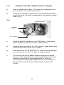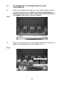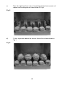
1
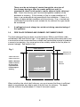
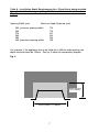
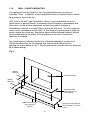
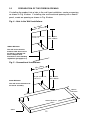
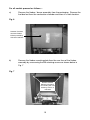
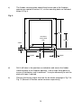
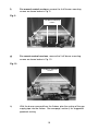
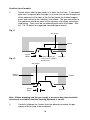
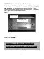
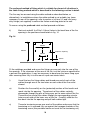
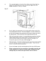
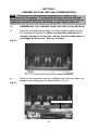
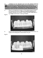
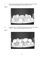
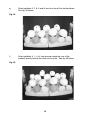
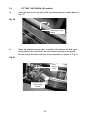
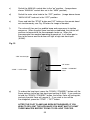
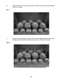
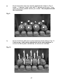
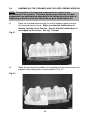
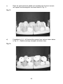
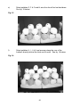
Vesta
INSET FUEL EFFECT GAS FIRE
Installation, Maintenance & User Instructions
Hand these instructions to the user following installation
Model No’s FVTC**MN, FVTP**MN, FVTC**RN & FVTP**RN are only
for use on Natural Gas (G20) at a supply pressure of 20 mbar in G.B.
/ I.E.
** denotes colour variant
Section 1
1.0
1.1
1.2
1.3
1.4
1.5
1.6
1.7
1.8
1.9
1.10
1.11
4.1
4.2
4.3
4.4
4.5
4.6
4.7
4.8
11
11
12-19
20
20
Assembling Fuel Bed and Commissioning
21-25
26-29
30
31
31-33
33
Maintenance
Removal
Removal
Removal
Removal
Removal
Removal
Removal
Removal
Section 5
5.1
5.2.1
5.2.2
5.2.3
5.3
5.4
5.5
5.6
5.7
5.8
Installation of Fire
Assembling the ceramics and fuel bed (coal models)
Assembling the ceramics and fuel bed (pebble models)
Fitting the Fascia
Lighting the appliance (MC Models)
Lighting the appliance (RC Models)
Checking for clearance of combustion
products
Section 4
PAGE
3
4
4
4
5
5
6
8
8
8
9
10
Unpacking the fire
Installing the Firebox
Preparation of Firebox Opening
Gas tightness and burner pressure (MC Models)
Gas tightness and burner pressure (RC Models)
Section 3
3.1
3.2
3.3
3.4
3.5
3.6
Information and Requirements
Appliance Information
Conditions of Installation
Flue and chimney suitability
Fireplace / surround suitability
Shelf position
Chimney inspection
Fire place opening / catchment space
Fitting to Chair bricks
Precast Flues
Metal Flue boxes
Wall / Hearth Mounting
Spillage Monitoring System
Section 2
2.1
2.2
2.3
2.4
2.4
CONTENTS
of
of
of
of
of
of
of
of
the
the
the
the
the
the
the
the
Burner Assembly (Manual)
Piezo Igniter
Control Tap
Pilot Assembly
Burner Assembly (Remote)
RC Valve
Pilot Assembly
Batteries in the IR Reciever
34
35
35
35
36
36
36-37
37
User Instructions
Conditions of Installation
Operating the Fire (MC models)
Operating the Fire (RC models)
Spillage Monitoring System
Re-Assembling the fuel-bed (coal models)
Re-Assembling the fuel-bed (pebble models)
Cleaning the Fire
Cleaning the Fuel-bed
Removal & Re-Fitting the Fascia
User Replaceable Parts
39
41
42-43
43
44-48
49-52
52
52
53
53
This appliance is manufactured by :- BFM Europe Ltd, Trentham Lakes, Stoke-on-Trent, ST4 4TJ
2
SECTION 1
INFORMATION AND REQUIREMENTS
1.0
APPLIANCE INFORMATION
Model
FVTC**MN, FVTP**MN, FVTC**RN &
FVTP**RN
G20
Gas Type
Main injectors (2 off)
Pilot Type
Size 235
S.I.T. Oxystop
YA OP 9022 (MC & RC)
Max. Gross Heat Input :
Min. Gross Heat Input :
6.5 kW
4.2 kW
Cold Pressure :
Cold Pressure :
FVTC / P**MN - 20.0 +/-1.0 mbar
FVTC / P**RN - 20.0 +/-1.0 mbar
Ignition :
Push-button Piezo (Manual models)
6V Battery Generator (Remote models)
Electrode Spark Gap
Weight
4.0mm
All models
MC 19 Kg, RC 20kG
Fire box Dimensions (with fascia fitted)
Width :
Height :
Depth :
Depth :
(with fascia fitted)
(with fascia fitted)
(overall-with fascia)
(from mounting face)
Gas Connection
Efficiency Declaration
753mm
559mm
198mm
70mm
8mm Compression
(Supplied with fire)
The efficiency of this appliance has been measured as specified in
BS 7977-1 : 2002 and the result is 55%.
The gross calorific value of the fuel has been used for this efficiency
calculation.
The test data from which it has been calculated has been certified by Advantica.
The efficiency value may be used in the UK Government’s Standard Assessment
Procedure (SAP) for energy rating of dwellings.
3
INSTALLATION REQUIREMENTS
1.1
CONDITIONS OF INSTALLATION
It is the law that all gas appliances are installed only by a CORGI Registered
Installer, in accordance with these installation instructions and the Gas Safety
(Installation and Use) Regulations 1998 as amended. Failure to install appliances
correctly could lead to prosecution. It is in your own interest and that of safety to
comply with the law.
The installation must also be in accordance with all relevant parts of the Local and
National Building Regulations where appropriate, the Building Regulations
(Scotland Consolidation) issued by the Scottish Development Department, and all
applicable requirements of the following British Standard Code of Practice.
1.
2.
3.
4.
5.
6.
7.
BS 5871 Part 2 Installation of Inset Live Fuel Effect Gas Fires
BS 6891 Installation of Gas Pipework
BS 5440 Parts 1 & 2 Installation of Flues and Ventilation
BS 1251 Open fire place components
BS 715 / BS EN 1856-2 Metal flue pipes for gas appliances
BS EN 1858 Clay Flue Blocks and Terminals
IS 813 : 1996 Domestic Gas Installation (Republic of Ireland)
No purpose made additional ventilation is normally required for this
appliance, when installed in G.B. When Installing in I.E. please consult
document I.S. 813 : 1996 Domestic Gas Installation, which is issued by the
National Standards Authority of Ireland. If installing in Northern Ireland,
please consult local building regulations. Any purpose made ventilation
must be checked periodically to ensure that it is free from obstruction.
1.2
FLUE AND CHIMNEY SUITABILITY
This appliance is designed for use with conventional brick built or lined chimneys
and fabricated flues and metal flue boxes conforming to BS 715 / BS EN 1856-2.
All flues must conform to the following minimum dimensions.
Minimum diameter of circular flues
Minimum effective height of all flue types
125 mm (Without Flue
Restrictor Fitted)
3 metres
When fitting to conventional chimneys or 175mm flues it may be desirable to
fit the flue restrictor baffle (supplied) to reduce the flue flow and increase the
efficiency of the fire. Safe clearance of products must always be checked by
carrying out a smoke match test as described.
4
1.3
FIREPLACE / SURROUND SUITABILITY
The fire must not be installed directly onto carpet or other combustible floor
materials. See page 9 for further details regarding hearth panels.
The fire is suitable for fitting to non-combustible fire place surrounds and
proprietary fire place surrounds with a temperature rating of at least 150oc.
If a heating appliance is fitted directly against a wall without the use of a fire
surround or fire place all combustible material must be removed from behind
the trim. Soft wall coverings such as blown vinyl, wall paper etc. could be
affected by the rising hot air and scorching and/or discoloration may result.
Due consideration should be made to this when installing or decorating.
1.4
SHELF POSITION
The fire may be fitted below a combustible shelf providing there is a minimum
distance of 200mm above the top of the fire and the shelf does not project more
than 150mm. If the shelf overhangs more than 150mm the distance between the
fire and the shelf must be increased by 15mm for every 25mm of additional overhang over 150mm.
1.5
FLUE / CHIMNEY INSPECTION
Before commencing installation, a flue or chimney should be inspected to ensure
that all the following conditions are satisfied.
1.
Check that the chimney / flue only serves one fire place and is clear of any
obstruction. Any dampers or register plates must be removed or locked in
the open position.
2.
Brick/stone built chimneys or any chimney or flue which has been used for
an appliance burning fuel other than gas must be thoroughly swept. The
base of the chimney / flue must also be thoroughly cleared of debris etc.
3.
Any under-floor air supply to the fire place must be completely sealed off.
4.
Ensure that the inside of the chimney / flue is in good condition along it’s
length and check that there is no leakage of smoke through the structure
of the chimney during and after the smoke pellet test. With pre-cast flues
it is especially important to check the inside of the flue for extruded
cement / sealant protruding from the joints between the flue
blocks. If present, these should be removed by rodding the flue
before proceeding with the installation.
5.
Using a smoke pellet, check that there is an up-draught in the chim
ney / flue and that the smoke can be seen issuing from the terminal /
chimney pot outside.
5
There must be no leakage of smoke through the structure of
the chimney during or after the smoke pellet test and it is
important to check inside upstairs rooms adjacent to the chimney /
flue. Check the chimney pot / terminal and general condition of the
brickwork or masonry. If the chimney or flue is in poor condition or if
there is no up-draught do not proceed with the installation. If there is a
history of down-draught conditions with the chimney / flue, a tested and
certificated flue terminal or cowl suitable for the relevant flue type should
be considered.
6.
A spillage test must always be carried out during commissioning of
the appliance.
1.6
FIRE PLACE OPENING AND CHIMNEY CATCHMENT SPACE
The front opening of the fire place must be between 350mm and 400mm wide,
and between 490 and 500mm high. If the opening exceeds these dimensions then
a surround must be constructed from suitable non-combustible material to produce
a correct size opening. Any surround must be suitably sealed to the fire place to
prevent leakage. See below in fig.1
Fig. 1
490mm Minimum
500mm Maximum
NOTE : Minimum
25mm clearance
for fascia also
required below
bottom edge of
opening
420mm Minimum
Fire Opening
350mm Minimum
400mm Maximum
Minimum Flat
Sealing Area
520mm
Minimum
When installing into a brick built chimney, you must ensure that there is sufficient
depth to accomodate any debris which may fall from the chimney. This depth
must be sufficient to accomodate 12 litres of volumetric space.
6
Table A - Installation Depth Requirements for a Flavel Vesta being installed
into a brick built chimney, requiring 12.0 litres of debris collection volume
(Fig. 2).
Opening Width (mm)
Minimum Depth Required (mm)
350 (minimum opening width)
360
370
380
390
400 (maximum opening width)
173
170
167
163
158
155
For example, if the appliance was to be fitted into a 400mm wide opening, the
depth required would be 155mm. See fig. 2 below for explanatory diagram.
Fig. 2
Depth Required
(e.g. 155mm)
Opening Width ( e.g. 400mm)
7
1.7 FITTING TO FIREPLACES WITH EXISTING CHAIRBRICKS AND
CONVENTIONAL BRICKBUILT CHIMNEYS
This appliance is suitable for use in fireplaces fitted with an existing chairbrick
without the need for removal of the chairbrick, providing the minimum depth of the
fireplace exceeds 190mm. If the depth is less than 190mm then the spacer
(optional) must be used to give a minimum clearance from the rear of the fire to
the rear of the chairbrick of at least 90mm to allow sufficient space for the collection of debris which may fall down the chimney. The fireplace must be checked to
ensure that no part of the chairbrick is within 50mm of the flue outlet of the fire
when installed.
1.8 FITTING TO PRE-CAST FLUE INSTALLATIONS
To install the fire box in to pre-cast flue starter blocks, there must be at least
100mm from the mounting face of the fire to the rear of the pre-cast flue
starter block to allow sufficient space for debris collection. It is important to
consider this depth if choosing a fire surround as the thickness of the fire surround
must be sufficient to give a total depth of at least 100mm to the rear of the
starter block, otherwise there will be insufficient depth. To increase this depth the
fire surround may be packed away from the wall using suitable non-combustible
board, providing the installation is correctly sealed. If in doubt about the suitability
of the fire contact BFM Europe Ltd. for advice before proceeding.
It is important to ensure that the pre-cast flue is in good condition and is free from
extruded mortar or sealant from between the flue blocks.
This appliance has been tested for use in a pre-cast flue block complying
with BS EN 1858. In accordance with BS EN 1858, pre-cast flues built with
directly plastered faces (front or rear) are not correctly installed as to ensure
proper operation with any type of gas fire. In some instances of this flue
construction, temperature cracking of surface plaster may occur through no
fault of the appliance. An air gap or some form of insulation material should
be installed to prevent normal flue temperatures from damaging wall
surfaces.
1.9 FITTING TO PRE-FABRICATED TWIN WALL METAL FLUE BOXES
The appliance may be fitted to twin wall metal flue boxes conforming to the
constructional requirements of BS 715, (for example the Selkirk LFE 125 box).
The box must have a minimum flue diameter of 125mm internal and minimum
internal dimensions of 160mm deep by 490mm high by 350mm wide. There are
no maximum dimensional requirements for the box. The top face of the box must
be insulated with a minimum thickness of 50mm of non-combustible mineral wool
insulation or similar material. The flue box must stand on a non-combustible base
of minimum thickness 12mm.
8
1.10
WALL / HEARTH MOUNTING
This appliance must be fitted on a flat, non-combustible base of minimum
thickness 12mm. In addition, a non-combustible hearth or physical barrier should
be provided in front of the fire.
With “hole in the wall” type installations, where it may be desirable not to fit a
hearth panel or physical barrier, the product may be installed in accordance with
Document J of the building regulations so that every part of theflame or
incandescent material is at least 225mm above the floor level. For the customers
safety, and in accordance with BS 5871-2, the fitting of a hearth panel or physical
barrier should be carried out. Should this advice not be followed however, please
give consideration to the safety of the occupants in the room to which the
appliance is installed.
Any hearth panel or physical barrier that is fitted should project a mnimum of
300mm forwards from the fire opening and 150mm either side of the fire
opening, as shown below in Fig. 3 Any physical barrier must be securely fixed and
be of robust design.
Fig. 3
300mm
Minimum
Fireplace Opening
300mm
Minimum
Example of Wall
Mounted Physical /
Tactile Barrier
150mm Minimum each
side of fireplace
opening
9
Example of Floor Mounted
Physical Barrier i.e. Hearth
Panel
1.11
SPILLAGE MONITORING SYSTEM
This appliance is fitted with an atmosphere sensing spillage monitoring system in
the form of an oxygen sensing pilot. This is designed to shut the fire off in the
event of a partial or complete blockage of the flue causing a build up of
combustion products in the room in which the fire is operated. The following are
important warnings relating to this spillage monitoring system :1) The spillage monitoring system must not be adjusted by the installer.
2) The spillage monitoring system must not be put out of operation.
3) When the spillage monitoring system is exchanged only a complete original
manufacturers part may be fitted. It is not possible to replace individual parts on
the pilot system on this appliance, only a complete pilot assembly (including the
thermocouple) may be fitted.
10
SECTION 2
INSTALLATION OF FIRE
2.1
UNPACKING THE FIRE
Carefully lift the fire out of the carton. Remove the loose item packaging carefully
from the front of the appliance. Check the contents as listed :Packing Check List
1off
1off
1off
1off
1off
2.2
Fire box / burner assembly
Boxed ceramic base, 2 piece ceramic front rail 11 synthetic coals or
pebbles
Loose items bag.
Installation and user instruction book (Combined)
Flue restrictor baffle (for use in brick built chimneys and large diameter
e.g. 175mm flue applications).
INSTALLING THE FIRE BOX
Establish which type of flue you are intending to install the fire in to :225 x 225mm (9 inch x 9 inch) brick built chimneys
175mm (7 inch) diameter lined brick or stone flue, insulated pre-fabricated
metal flue box to BS 715 / BS EN 1856-2 or Pre-Cast Flue to BS EN 1858
When installing into 125mm (5 inch) diameter lined brick or stone flue, or
insulated pre-fabricated metal flue box to BS 715 / BS EN 1856-2 and
pre-cast flues the restrictor baffle must not be fitted.
A spillage test must always be carried out to check satisfactory
clearance of flue products, regardless of the type of flue the
appliance is being fitted to.
This product is designed to fit into a standard set of pre-cast starter
blocks, without needing to move the blocks within the wall cavity. If
the customer requires the product to be fitted at a height which
requires modification to the pre-cast flue system, please consult a
structural engineer regarding the re-positioning of the starter /
collection blocks of the pre-cast flue syste,
UNDER NO CIRCUMSTANCES SHOULD THE FIRE BE RECESSED INTO THE
GATHER BLOCK, OFFSET OR STRAIGHT FLUE BLOCKS.
11
2.3
PREPARATION OF THE FIREBOX OPENING
If installing the product into a hole in the wall type installation, create an opening
as shown in Fig. 4 below. If installing into a conventional opening with a hearth
panel, create an opening as shown in Fig. 5 below.
Fig. 4 - Hole in the Wall Installations
50mm
Min. 3 0mm
40
.
x
a
M
As per section 1.6,
1.8 or 1.9
Min. 490mm
Max. 500mm
100mm Minimum
This will ensure that the
distance from floor level to
the burner is 225mm and
hence complies with
Document J of the building
regulations (paragraph 3.4)
Fig. 5 - Conventional Installations
50mm
Min. 3 0mm
40
.
x
a
M
65mm Minimum
As per section 1.6,
1.8 or 1.9
Min. 490mm
Max. 500mm
This will ensure clearance for
the fascia assembly
300mm
Minimum
750mm Minimum
50mm
12
For all models proceed as follows :a)
Remove the firebox / burner assembly from the packaging. Remove the
fuel-bed set from the combustion chamber and store in a safe location.
Fig. 6
Remove Fuel-bed
Set from Firebox
before proceeding
with the installation
b)
Remove the firebox mounting plate from the rear face of the firebox
assembly by unscrewing the M5 retaining screws as shown below in
Fig. 7
Fig. 7
Remove Firebox
Mounting Frame by
Unscrewing the 4 off
retaining screws as
indicated
13
c)
The firebox mounting plate should then be secured to the fireplace
opening as created in section 2.3, via the mounting holes as indicated
below in Fig. 8.
Fig. 8
7mm Base
Centre Hole
Only
20mm
215mm
430mm
500mm
250mm
20mm
d)
Drill 8 off holes in the positions as indicated, and secure the firebox
mounting plate to the fireplace opening. Use all eight fixing points to
ensure a satisfactory seal is achieved. It may be necessary to seal the
plate with tape if required.
e)
Remove the burner engine from the fire as shown overpage in Fig. 9 &
Fig. 10 (Manual & Remote control versions respectively).
14
f)
Fig. 9
g)
For manual control versions, remove the 4 off burner mounting
screws as shown below in Fig. 9
4 off Burner Retaining
screws
For remote control versions, remove the 2 off burner mounting
screws as shown below in Fig. 10
Fig. 10
2 off Burner Retaining
Screws
h)
With the burner removed from the firebox, plan the routing of the gas
supply pipe into the firebox. See overpage, section i) for suggested
pipework routing.
15
Continue for all models
i)
Decide which side the gas supply is to enter the fire from. If concealed
pipe work is required plan the pipe run to enter the fire box through one
of the openings in the sides of the fire box below the fuelbed support
panel and connect to the isolating / inlet elbow. The gas connection to
the appliance should be made to the isolating / inlet elbow using 8mm
rigid tubing. There must be no soldered joints within the firebox. See
fig. 11 & 12 below for suggested concealed pipe layouts.
Fig. 11
Gas Supply
Firebox
Approx.
40mm
Fig. 12
Gas Supply
Purpose shaped gas
supply pipe is supplied
for R/H entry
Fireplace
Builders
Opening
Firebox
Approx.
40mm
Fireplace
Note : Before breaking into the gas supply a pressure drop test should be
carried out to establish that the existing pipework is sound.
j)
Carefully withdraw the fire box from the opening to enable the gas
supply and fire fixing to be completed.
16
IMPORTANT : Sealing of the Gas Unused Gas Pipe Inlet Apertures
In line with current CORGI regulations, it is imperative that the gas supply inlet
apertures that are not utilised during the installation are sealed with the foil
tape as supplied. Failure to seal these inlet apertures could lead to flame
reversal, which in turn will damage the burner and control systems of the product.
Fig. 13 below shows a correctly sealed installation.
Fig. 13
Only holes to be left is
the gas inlet aperture
that is used
Seal off unused gas inlet
apertures and cable fixing holes
as shown
PLEASE NOTE :BFM EUROPE LTD. WILL NOT BE LIABLE FOR
GUARANTEE CLAIMS THAT ARE AS A DIRECT
RESULT OF THE UNUSED GAS INLET APERTURES
NOT BEING CORRECTLY SEALED.
17
The preferred method of fixing which is suitable for almost all situations is
the cable fixing method which is described in the following section in detail.
The fire may be secured using the cable method as described below, or
alternatively, in installations where the cable method is not suitable (eg. loose
masonary in rear of fire opening), refer to section c) of item 2.3 and use heavy
duty fixings (not supplied) to secure the firebox mounting plate to the wall.
To secure using the preferred cable method proceed as followsk)
Mark out and drill 4 off No 14 (6mm) holes in the back face of the fire
opening in the positions shown below in fig. 14
Fig. 14
250mm
500mm
100mm
Fireplace Opening
20mm
Fit the wallplugs provided and screw the fixing eyes securely into the rear of the
fire opening. If the clearance at the rear of the fire is at the minimum specified for
a precast flue application, it may be necessary to bend over the lower fixing eyes
after screwing them fully in to the rear of a pre-cast starter block.
l)
Uncoil the two fire fixing cables and thread one end of each of the
cables through one of the two holes on each side of the flue outlet
shroud.
m)
Position the fire carefully on the (protected) surface of the hearth and
reach into the fire opening. Thread each of the cables vertically
downwards through the pair of fixing eyes on the same side of the fire.
Thread the free end of the cables through the corresponding circular
hole on each side of the lower rear of the fire. Carefully slide the fire
box back into the fire opening and pull both cables tight.
n)
Thread a tensioning screw over each of the cables and ensure that the
tensioning nut is screwed fully up against the hexagon shoulder of the
tensioning screw (this provides maximum travel for the tensioning nut).
18
o)
Fit a screwed nipple on to each of the cables and pull hand tight up
against the tensioning screw, then secure each nipple with a flat
bladed screwdriver. See fig. 15 below
Fig. 15
p)
Evenly tighten the tensioning nuts to tension both cables and pull the
fire snugly against the wall. Do not overtighten, it is only necessary to
pull the seal up against the sealing face of the wall, it does not need to
be compressed. Check that there are no gaps behind the seal.
q)
With the fire securely in place, if a concealed gas connection has been
made through either of the access holes in the sides of the fire, the
holes should be closed around the pipe to prevent leakage of air
through the gap around the pipe, refer to page 17.
r)
Refit the burner. Fit the four retaining screws on manual control models
and two retaining screws on remote control models. Check that the
burner is correctly locked into position.
s)
Secure the firebox into the mounting plate with the four off M5 screws.
t)
Before making the final gas connection, thoroughly purge the gas
supply pipework to remove all foreign matter, otherwise serious
damage may be caused to the gas control valve on the fire.
19
2.4
GAS TIGHTNESS AND BURNER PRESSURE (MANUAL CONTROL
MODELS)
a)
Remove the pressure test point screw from the inlet elbow and fit a
manometer.
b)
Turn on the main gas supply and carry out a gas tightness test.
c)
Depress the control knob and turn anti-clockwise to the position marked
pilot. Hold in the control knob for a few seconds to purge the pipe work
then press the igniter button. The burner should light, continue to hold
the control knob for a few seconds then turn to the full-on position.
d)
Check that the gas pressure is 20.0 mbar (+/- 1.0mbar) 8.0 in w.g.(+/0.4 in w.g.) for FVTC**MN & FVTP**MN models.
e)
Turn off the fire, remove the manometer and refit the pressure test point
screw. Check the pressure test point screw for gas tightness with the
appliance turned on using a suitable leak detection fluid or detector.
2.5
GAS TIGHTNESS AND BURNER PRESSURE (REMOTE CONTROL
MODELS).
a)
Remove the pressure test point screw from the inlet elbow and fit a
manometer.
b)
Turn on the main gas supply and carry out a gas tightness test.
c)
Depress both the round buttons on the handset. The fire will then
commence its ignition sequence and will light to high. See page 25
for full details of the operating method for the fire.
d)
Check that the gas pressure is 20.0 mbar (+/- 1.0mbar) 8.0 in w.g.(+/0.4 in w.g.) for FVTC**RN & FVTP**RN models.
e)
Turn off the fire, remove the manometer and refit the pressure test point
screw. Check the pressure test point screw for gas tightness with the
appliance turned on using a suitable leak detection fluid or detector.
20
SECTION 3
ASSEMBLING FUEL BED AND COMMISSIONING
NOTE : The position of the fuel-bed components are critical to the
performance of the product. Therefore please ensure that the fuel-bed
components are positioned as described in the following section prior to
requesting a service call due to soot build up, poor flame pattern etc.
3.1
ASSEMBLING THE CERAMICS AND FUEL BED (COAL MODELS)
a)
Place the fuel-bed base centrally on to the fuelbed support and pull
fully forwards to the burner. Make sure that the fuelbed base is
located centrally in the fire box. Ensure that the fuelbed base is
not lodged on the burner. See fig. 16 below.
Fig. 16
b)
Fig. 17
Place the left hand front coal rail moulding onto the front ceramic rail
support and locating pins as shown below in Fig. 17
Front Ceramic Rail Support
21
c)
Place the right hand front coal rail moulding onto the front ceramic rail
support and locating pins as shown below in Fig. 18.
Fig. 18
d)
Fit four large coals behind the ceramic front rails as shown below in
Fig. 19
Fig. 19
22
e)
Select three of the small coals and fit onto the ribs of the fuel-bed base.
See fig. 20 below
Fig. 20
f)
Select the remaining four small coals and arrange along the rear of the
fuelbed, directly behind the third row of coals. See fig. 21 below.
Fig. 21
23
g)
Ensure the coals sizes are correctly positioned as shown in Fig 22
below. “L” denotes “large” coals and “S” denotes small coals. If any
coals are missing, please contact your retailer. Do not proceed with
the installation.
Fig. 22
S
L
h)
S
S
S
S
L
L
S
S
L
Ensure the flame paths are un-interrupted as shown below in Fig. 23. If
necessary, make minor adjustments to the coal positions to ensure
the flame paths indicated by the arrows are available.
Fig. 23
Warning : Use only the coals supplied with the fire. When replacing the
coals remove the old coals and discard them. Fit a complete set of
coals of the correct type. Do not fit additional coals or any coals
other than a genuine replacement set.
24
To ensure that the release of fibres from these R.C.F (Refractory Ceramic
Fibre) articles is kept to a minimum, during installation and servicing we
recommend that you use a HEPA filtered vacuum to remove any dust
accumulated in and around the appliance before and after working on the
appliance. When replacing these articles we recommend that the replaced
items are not broken up, but are sealed within heavy duty polythene bags,
clearly labelled as “RCF waste”. RCF waste is classed as a “stable”, non
reactive hazardous waste and may be disposed of at a landfill licensed to
accept such waste Protective clothing is not required when handling these
articles, but we recommend you follow the normal hygiene rules of not
smoking, eating or drinking in the work area, and always wash your hands
before eating or drinking.
25
3.2
ASSEMBLING THE CERAMICS AND FUEL BED (PEBBLE MODELS)
NOTE : The position of the fuel-bed components are critical to the
performance of the product. Therefore please ensure that the fuel-bed
components are positioned as described in the following section prior to
requesting a service call due to soot build up, poor flame pattern etc.
a)
Fig. 24
b)
Place the fuel-bed base centrally on to the fuelbed support and pull
fully forwards to the burner. Make sure that the fuelbed base is
located centrally in the fire box. Ensure that the fuelbed base is
not lodged on the burner. See fig. 24 below.
Place the left hand front pebble rail moulding onto the front ceramic rail
support and locating pins as shown below in Fig. 25
Fig. 25
26
c)
Place the right hand front pebble rail moulding onto the front ceramic
rail support and locating pins as shown below in Fig. 26
Fig. 26
d)
Fit pebbles A, B, C, & D behind the ceramic front rails as shown below
in Fig. 27. (Pebble markings stamped into bottom face)
Fig. 27
A
C
B
27
D
e)
Select pebbles E, F & G and fit onto the ribs of the fuel-bed base.
See fig. 28 below.
Fig. 28
f)
G
F
E
Select pebbles H, I, J & K and arrange along the rear of the
fuelbed, directly behind the third row of coals. See fig. 29 below.
Fig. 29
H
I
J
28
K
Warning : Use only the pebbles supplied with the fire. When replacing the
pebbles remove the old pebbles and discard them. Fit a complete
set of pebbles of the correct type. Do not fit additional pebbles or
any pebbles other than a genuine replacement set.
To ensure that the release of fibres from these R.C.F (Refractory Ceramic
Fibre) articles is kept to a minimum, during installation and servicing we
recommend that you use a HEPA filtered vacuum to remove any dust
accumulated in and around the appliance before and after working on the
appliance. When replacing these articles we recommend that the replaced
items are not broken up, but are sealed within heavy duty polythene bags,
clearly labelled as “RCF waste”. RCF waste is classed as a “stable”, non
reactive hazardous waste and may be disposed of at a landfill licensed to
accept such waste Protective clothing is not required when handling these
articles, but we recommend you follow the normal hygiene rules of not
smoking, eating or drinking in the work area, and always wash your hands
before eating or drinking.
29
3.3
a)
Fig. 30
FITTING THE FASCIA (All models)
Hook the fascia over the top of the mounting flange as shown below in
Fig. 30
Hook fascia over the
mounting lip on the
firebox
b)
Fig. 31
Open the controls access door. Located at the bottom left and right
hand sides of the fireox base are two fascia retaining screw points.
Secure fascia to firebox with the screws provided as shown in Fig. 31
Fascia
securing
screws
Controls Access
Door in Open
Position
30
3.4
LIGHTING THE APPLIANCE (Manual Control Models)
a)
Turn on the gas isolation tap.
b)
Depress the control knob and turn anti-clockwise to the position
marked pilot. Hold in the control knob for a few seconds to purge the
pipe work.
c)
Continue to hold-in the control knob and press the igniter button. If the
burner does not light, continue to press the igniter button until ignition
occurs. Continue to hold the control knob for 5-10 seconds to allow the
thermocouple to heat up, if the pilot goes out when the control knob is
released, repeat the lighting sequence.
d)
Turn the control knob in the anti-clockwise direction to the high position
and the main burner will light.
e)
Turn the control knob clockwise to the low position and the gas input
will be reduced to the minimum setting.
f)
Slightly depress the control knob and turn to the pilot position, the main
burner will go out but the pilot will remain lit.
g)
Slightly depress the control knob and turn to the off position, the pilot
will now be extinguished.
3.5
LIGHTING THE APPLIANCE (Remote Control Models)
a)
The control valve is positioned in the centre of the fire when
viewed from the front.
b)
To operate the appliance automatically via the remote control handset,
ensure that the on / off switch is switched to the “on” position as shown
below in Fig. 32
Fig. 32
“MAIN VALVE” Knob
“MANUAL”
Control Disk
On / Off Switch
31
c)
Switch the MANUAL control disc to the “on” position. (Image above
shows “MANUAL” control disc set in the “MAN” position).
d)
Switch the main valve knob to the “OFF” position. (Image above shows
“MAIN VALVE” knob set in the “OFF” position.
e)
Press and hold the “STAR” button and “UP” button on the remote hand
set simultaneously, see Fig. 33 below for image of handset.
f)
The valve will then emit an audible beep and commence its ignition
sequence. When the pilot flame has been established, the control will
continue to beep whilst the thermocouple heats up. When the
thermocouple has reached operating temperature, it will allow gas to
flow to the burner and the burner will light at high rate heat input
(6.5kW).
Fig. 33
“LED” handset light
“UP” button
“DOWN” / “STANDBY”
button
“STAR” / “OFF” button
g)
To reduce the heat input, press the “DOWN / STANDBY” button until the
flame reduces to the low rate heat input setting (3.5kW). If you continue
to hold the “DOWN / STANDBY” button, the burner flame will extinguish,
and only the pilot flame will remain lit. If you wish to turn off the
fire altogether, press the “STAR” / “OFF” button.
AFTER THE PILOT FLAME HAS BEEN EXTINGUISHED, IF YOU
WISH TO RE-LIGHT THE APPLIANCE YOU MUST WAIT AT LEAST
THREE MINUTES BEFORE TRYING TO RE-LIGHT THE FIRE.
32
h)
Should the handset be misplaced, you can turn the fire off by switching
the “ON / OFF” switch to the “OFF” position.
3.6
CHECKING FOR CLEARANCE OF COMBUSTION PRODUCTS
a)
Close all doors and windows in the room.
b)
Light the fire and allow to run for approximately 5 minutes on high
position.
c)
After approximately 5 minutes hold a smoke match just inside and
below the centre of the lower front edge of the top of the fire. (It is
recommended that a suitable smoke match holder is used when check
ing for clearance of combustion products). All smoke generated should
be drawn back into the flue. If slight spillage occurs or if in doubt,
repeat the test after a further 5-10 minutes. If the test indicates that
spillage is occurring and the flue restrictor baffle has been fitted, it
should be removed and the test repeated after the fire has cooled.
d)
If spillage persists, the flue is not functioning correctly and a fault exists.
If, after investigation the fault cannot be traced and rectified, the fire
must be disconnected from the gas supply and expert advice obtained.
e)
If there is an extractor fan fitted any where in the vicinity of the
appliance, the spillage test should be repeated with the fan running on
maximum and all interconnecting doors open.
f)
After ensuring that the fire is safe to use it should be left on high
position to fully warm up. During this time a slight odour may be
noticed, this is due to the “newness” of the fire and will soon disappear.
At this stage any minor adjustments to the coals should be made using
suitable long handled tongs and taking care not to damage the coals.
Finally, hand the Installation and Maintenance Instructions and the
Users Instructions over to the customer and explain the operation of the
fire.
33
SECTION 4
MAINTENANCE
Servicing Notes
Servicing should be carried out annually by a competent person such as a CORGI
registered engineer. This is a condition of the BFM Europe Ltd. extended
guarantee schemes.
The service should include visually checking the chimney and fire opening for
accumulations of debris and a smoke test to check for a positive up-draught in the
chimney.
The condition of the coals should be checked and if necessary the whole set
should be replaced with a genuine replacement set.
The burner assembly is designed to be removed as a complete unit for ease of
access. After any servicing work a gas tightness check must always be
carried out.
Manual Control Fires – For Diagrams refer to Section 2
4.1
Removing the burner assembly from the fire.
4.1.1
Prepare work area (lay down dust sheets etc.)
4.1.2
To remove the fascia, open the controls access door at the bottom of
the fascia. This will allow access to the fascia retaining screws, located
at the bottom left and right hand sides of the firebox. Remove these
screws and lift the fascia clear. Remove the loose coals from the fuel
bed and the front ceramic rail. Remove the front ceramic from the rail.
Unscrew the two pozi-driv fixing screws which secure the burner heat
shield and remove it from the fire.
4.1.3
Isolate the gas supply and remove the inlet pipe from the appliance
inlet elbow. Unscrew and remove the four screws which retain the
burner. Remove the burner assembly from the fire.
4.1.4
To refit the burner assembly. Push the base of the control panel fully
into the fire and secure with the four screws. Refit the gas supply pipe
and carry out a gas tightness test. Refit the coals referring to section 3
for the correct coal layout. The fascia can now be replaced by hooking
it over the top flange of the mounting frame and securing via the two
screws, accessed through the controls opening door.
34
4.2
Removing the Piezo Igniter
4.2.1
Remove the burner assembly as in section 4.1
4.2.2
Disconnect the ignition lead from the piezo and unscrew the
retaining nut on the rear of the control panel. Withdraw the piezo from
the front of the control panel. Reassemble in reverse order and carry
out a gas tightness test.
4.3
Removing the Control Tap from the fire.
4.3.1
Remove the burner assembly as in section 4.1.
4.3.2
Pull the control knob off the control tap spindle.
4.3.3
Loosen and remove the three gas pipe retaining nuts from the control
tap and release the ends of the gas pipes from the control tap body.
Loosen and remove the thermocouple securing nut from the end of the
control tap.
4.3.4
Unscrew the control tap locknut from the front of the control panel and
remove the control tap.
4.3.5
To refit a control tap, reassemble in reverse order noting that the control
tap locates with a flat in the control panel. Carry out a gas tightness
test after re-assembly.
4.4
Removing the Oxy-Pilot Assembly
Note : Because this appliance is fitted with an atmosphere sensing ‘OxyPilot’ it is not possible to replace the thermocouple separately, because the
thermocouple position is factory set to a tight tolerance. Any replacement of
parts on the pilot requires a complete new pilot assembly.
4.4.1
Remove the burner assembly as in section 4.1
4.4.2
Unscrew and remove the thermocouple retaining nut from the end of the
control tap and disconnect the ignition lead from the pilot electrode.
4.4.3
Unscrew and remove the two pozi-driv screws which secure the pilot
assembly to the burner. Remove the pilot.
4.4.4
Re-assemble in reverse order and carry out a gas tightness test.
35
Remote Control Fires - For Diagrams refer to section 2
4.5
Removing the RC Burner Assembly (RC models)
4.5.1
Prepare work area (lay down dust sheets etc.)
4.5.2
To remove the fascia, open the controls access door at the bottom of
the fascia. This will allow access to the fascia retaining screws, located
at the bottom left and right hand sides of the firebox. Remove these
screws and lift the fascia clear. Remove the coals, front ceramic from
the rail and fuel-bed base matrix. Remove all of the loose coals and
front ceramic rail. Unscrew the two pozi-drive fixing screws which
secure the burner heat shield and remove it from the fire.
4.5.3
Unscrew the 2 off burner retaining screws on the side brackets, the
burner should then be lifted out of the firebox.
NOTE : Please take care with the wiring loom
4.5.4
To refit the burner assembly, re-assemble in reverse order and carry out
a gas tightness test. Refit the coals referring to section 3
for the correct coal layout. The fascia can now be replaced by hooking
it over the top flange of the mounting frame and securing via the two
screws, accessed through the controls opening door.
4.6
Removing the Remote Gas Valve from the fire (RC models)
4.6.1
Prepare work area (lay down dust sheets etc.)
4.6.2
Remove the burner assembly as described in section 4.6.
4.6.3
Disconnect pilot, main and injector pipes and disconnect the wiring loom
thermocouple and ignition wire, the valve can then be removed.
Re-assemble in reverse order, Refit the coals referring to section 3
for the correct coal layout. The fascia can now be replaced by hooking
it over the top flange of the mounting frame and securing via the two
screws, accessed through the controls opening door.
4.7
Removing the Pilot Assembly (RC models)
Note : Because this appliance is fitted with an atmosphere sensing ‘OxyPilot’ it is not possible to replace the thermocouple separately, because the
thermocouple position is factory set to a tight tolerance. Any replacement of
parts on the pilot requires a complete new pilot assembly.
4.7.1
Prepare work area (lay down dust sheets etc.)
4.7.2
Remove the burner assembly as described in section 4.6
36
4.7.3
Loosen the pilot nut and remove the two screws retaining the pilot
assembly. Unscrew the thermocouple from the gas valve.
4.7.4
Re-assemble in reverse order, Refit the coals referring to section 3
for the correct coal layout. The fascia can now be replaced by hooking
it over the top flange of the mounting frame and securing via the two
screws, accessed through the controls opening door.
4.8
Replacing the Batteries (Within the Radio Frequency Receiver)
4.8.1
Prepare work area (lay down dust sheets etc.)
4.8.2
To remove the fascia, open the controls access door at the bottom of
the fascia. This will allow access to the fascia retaining screws, located
at the bottom left and right hand sides of the firebox. Remove these
screws and lift the fascia clear.
4.8.3
The RF receiver is located on the right hand side of the product, below
the burner assembly. Slide the RF reciever out, slide the battery cover
off and replace the batteries as necessary.
4.8.4
The fender and ash pan cover can now be re-positioned. Refit the trim.
NB
The handset uses one LR61 (9v) and should be replaced by
removing the cover on the rear of the handset.
ENSURE THE BATTERIES ARE CONNECTED TO THE CORRECT POLARITY
POSITVE (+), NEGATIVE (-)
37
PARTS SHORTLIST
Replacement of parts must be carried out by a competent person such as a
CORGI registered gas installer. The part numbers of the replaceable parts are as
follows, these are available from BFM Europe Ltd. who may be contacted at the
address shown below.
Complete coal / ceramic set
Coal Fuelbed base
Coal Fuelbed front rails (pair)
Replacement coal set
Complete pebble / ceramic set
Pebble Fuelbed base
Pebble Fuelbed front rail (L/H)
Pebble Fuelbed front rail (R/H)
Replacement pebble set
Piezo Igniter
Ignition Wire
Pilot Assy. (MC NG)
Manual Gas Valve (NG)
Remote Valve
B-107010
B-96400
B-96410
B-96420
B-107340
B-107350
B-107360
B-107370
B-107380
B-1320
B-14340
B-1350
B-102880
B-92200
38
SECTION FIVE - USER INSTRUCTIONS
5.1
INSTALLATION INFORMATION
CONDITIONS OF INSTALLATION
It is the law that all gas appliances are installed only by a competent (e.g. CORGI
Registered) Installer, in accordance with the installation instructions and the Gas
Safety (Installation and Use) Regulations 1998. Failure to install appliances
correctly could lead to prosecution. It is in your own interest and that of safety to
comply with the law.
The fire may be fitted below a combustible shelf provided that the shelf is at least
200mm above the top of the appliance and the depth of the shelf does not exceed
150mm.
The fire may be installed below combustible shelves which exceed 150mm deep
providing that the clearance above the fire is increased by 15mm for each 25mm
of additional overhang in excess of 150mm.
No purpose made additional ventilation is normally required for this
appliance when installed in G.B. When installed I.E. please consult document I.S. 813 : 1996 Domestic Gas Installation which is issued by the
National Standards Authority of Ireland. Any purpose made ventilation
should be checked periodically to ensure that it is free from obstruction.
If the chimney or flue has been previously used by appliances burning fuels other
than gas they must be swept prior to the installation of this fire.
If this appliance is fitted directly on to a wall without the use of a fireplace or
surround, soft wall coverings such as wallpaper, blown vinyl etc. could be affected
by the heat and hot convection air and may discolour or scorch. This should be
considered when installing or decorating.
The Model number of this appliance is as stated on the rating plate affixed to the
control panel of the fire and the appliance is manufactured by:BFM Europe Ltd
Trentham Lakes
Stoke on Trent
ST4 4TJ
39
ABOUT YOUR NEW VESTA
The Flavel Vesta coal & pebble effect gas fires incorporate a unique and highly
developed fuel bed which gives the realism of a loose coal layout combined with
realistic flames and glow. The use of durable ceramic material in the
construction of the fuelbed components ensures long and trouble free operation.
The fire incorporates a flame control (coal models only) which allows you to adjust
the flame appearance to give the desired combination of flames and glow. The left
hand position gives maximum radiant heat and output whereas the right hand
position gives more flame but slightly less glow.
When first using the new fire a slight smell may be noticed. This is due to starch
used in the manufacture of the soft ceramic coals, it is non-toxic and will soon
disappear.
Please take the time to fully read these instructions as you will then be able to
obtain the most effective and safe operation of your fire.
IMPORTANT SAFETY INFORMATION
WARNING
This appliance has a naked flame and as with all heating appliances a
fireguard should be used for the protection of children, the elderly and
infirm. Fireguards should conform to B.S. 8423 : 2002 (Fireguards for use
with gas heating appliances).
It is important that this appliance is serviced at least once a year by a CORGI
registered gas installer and that during the service the fire is removed from the fire
opening and the chimney or flue visually checked for fallen debris or blockages
which must be removed. The chimney should also be checked to ensure
clearance of flue products. We recommend that during the annual service,
replacement of the Oxypilot is carried out. This is a condition of the
manufacturers guarantee.
After installation or during servicing a spillage test must always be carried
out.
Rubbish of any type must NEVER be thrown onto the fuel bed, this could affect
safe operation and damage the fire.
Any debris or deposits should be removed from the fuel bed from time to time.
This may be carried out by referring to the cleaning section as described later in
this book. Only the correct number and type of coals / pebbles must be used and
only complete and genuine replacement sets must be used.
Always keep furniture and combustible materials well clear of the fire and never
dry clothing or items either on or near to the fire. Never use aerosols or
flammable cleaning products near to the fire when it is in use.
40
The ceramic fuel bed remains hot for a considerable period after use and
sufficient time should be allowed for the fire to cool before cleaning etc.
5.2.1
OPERATING THE FIRE (MANUAL CONTROL MODELS)
The controls are located behind the controls access door. The controls, comprise a
control valve to adjust the gas flow and a push button piezo igniter. There is also
a flame adjuster which slides from left to right (coal model only). The left hand
position gives maximum radiant heat and output whereas the right hand position
gives more flame but slightly less glow. To light the fire proceed as follows:1)
2)
Depress the control knob and turn anti-clockwise to the position
marked pilot. Hold in the control knob for a few seconds to allow the gas to
reach the pilot.
Continue to hold-in the control knob and press the igniter button. If the pilot
does not light, continue to press the igniter button until ignition occurs. The
pilot flame can be seen by looking at the left hand side front bottom corner of
the glass panel. When the pilot has lit, continue to hold the control knob in
for 5-10 seconds to allow the thermocouple to heat up, if the pilot goes out
when the control knob is released, repeat the lighting sequence.
In the unlikely event of a failure of the igniter, the fire can be lit as follows :Open the controls access door, depress the control knob and turn anti-clockwise to
the position marked pilot. Hold in the control knob for a few seconds to allow the
gas to reach the pilot. Insert the tip of a lit taper in behind the front ceramic rail on
the left hand side. This will light the pilot flame. When the pilot has lit,
continue to hold the control knob in for 5-10 seconds to allow the thermocouple to
heat up, if the pilot goes out when the control knob is released, repeat the lighting
sequence.
3)
4)
After lighting, turn the control knob in the anti-clockwise direction to the high
position and the main burner will light. For most efficient performance the
fire is allowed to warm up for a few minutes with the flame adjuster set to the
left hand position and the gas control on maximum.
The gas control can be turned clockwise from the maximum position to give
the desired heat output and the flame control adjusted (coal model only) to
give the most pleasing flame effect or maximum glow.
WARNING
If the fire goes out for any reason or is turned off and it is
necessary to re-light the fire it is important to allow the fire to cool
for 3 minutes before attempting to re-light it.
41
5.2.2
OPERATING THE FIRE - REMOTE CONTROL VARIANTS
a)
Open the controls access door. The control valve is positioned in the
centre of the fire when viewed from the front.
b)
To operate the appliance automatically via the remote control handset,
ensure that the on / off switch is switched to the “on” position as shown
below in Fig. 1
Fig. 1
“MAIN VALVE” Knob
“MANUAL”
Control Disk
On / Off Switch
c)
Switch the MANUAL control disc to the “ON” position. (Image above
shows “MANUAL” control disc set in the “MAN” position).
d)
Switch the main valve knob to the “OFF” position. (Image above shows
“MAIN VALVE” knob set in the “OFF” position.
e)
Press and hold the “STAR” button and “UP” button on the remote hand
set simultaneously, see Fig. 2 overpage for image of handset.
f)
The valve will then emit an audible beep and commence its ignition
sequence. When the pilot flame has been established, the control will
continue to beep whilst the thermocouple heats up. When the
thermocouple has reached operating temperature, it will allow gas to
flow to the burner and the burner will light at high rate heat input
(6.5kW).
42
Fig. 2
“LED” handset light
“UP” button
“DOWN” / “STANDBY”
button
“STAR” / “OFF” button
g)
To reduce the heat input, press the “DOWN / STANDBY” button until the
flame reduces to the low rate heat input setting (4.2kW). If you continue
to hold the “DOWN / STANDBY” button, the burner flame will extinguish,
and only the pilot flame will remain lit. If you wish to turn off the
fire altogether, press the “STAR” / “OFF” button.
AFTER THE PILOT FLAME HAS BEEN EXTINGUISHED, IF YOU
WISH TO RE-LIGHT THE APPLIANCE YOU MUST WAIT AT LEAST
THREE MINUTES BEFORE TRYING TO RE-LIGHT THE FIRE.
5.2.3
SPILLAGE MONITORING SYSTEM - Applicable to all models
This appliance is fitted with a spillage monitoring system which shuts down the fire
if the evacuation of combustion products from the fire is affected by a partially or
fully blocked flue. If this system operates the fire will go out. If this occurs, leave
the fire for at least three minutes then follow the lighting procedure as
described in the previous section. In the event of repeated operation a CORGI
registered gas installer must be called to investigate and rectify the cause.
43
5.3
RE-ASSEMBLING THE CERAMICS AND FUEL BED
(COAL MODELS)
a)
Place the fuel-bed base centrally on to the fuelbed support and pull
fully forwards to the burner. Make sure that the fuelbed base is
located centrally in the fire box. Ensure that the fuelbed base is
not lodged on the burner. See fig. 3 below.
Fig. 3
b)
Place the left hand front coal rail moulding onto the front ceramic rail
support and locating pins as shown below in Fig. 4
Fig. 4
Front Ceramic Rail Support
44
c)
Place the right hand front coal rail moulding onto the front ceramic rail
support and locating pins as shown below in Fig. 5
Fig. 5
d)
Fit four large coals behind the ceramic front rails as shown below in
Fig. 6
Fig. 6
45
e)
Select three of the small coals and fit onto the ribs of the fuel-bed base.
See fig. 7 below
Fig. 7
f)
Select the remaining four small coals and arrange along the rear of the
fuelbed, directly behind the third row of coals. See fig. 8 below.
Fig. 8
46
g)
Ensure the coals sizes are correctly positioned as shown in Fig. 9
below. “L” denotes “large” coals and “S” denotes small coals. If any
coals are missing, please contact your retailer. Do not proceed with
the installation.
Fig. 9
S
L
h)
S
S
S
S
L
L
S
S
L
Ensure the flame paths are un-interrupted as shown below in Fig. 10.
If necessary, make minor adjustments to the coal positions to
ensure the flame paths indicated by the arrows are available.
Fig. 10
47
Warning : Use only the coals supplied with the fire. When replacing the
coals remove the old coals and discard them. Fit a complete set of
coals of the correct type. Do not fit additional coals or any coals
other than a genuine replacement set.
To ensure that the release of fibres from these R.C.F (Refractory Ceramic
Fibre) articles is kept to a minimum, during installation and servicing we
recommend that you use a HEPA filtered vacuum to remove any dust
accumulated in and around the appliance before and after working on the
appliance. When replacing these articles we recommend that the replaced
items are not broken up, but are sealed within heavy duty polythene bags,
clearly labelled as “RCF waste”. RCF waste is classed as a “stable”, non
reactive hazardous waste and may be disposed of at a landfill licensed to
accept such waste Protective clothing is not required when handling these
articles, but we recommend you follow the normal hygiene rules of not
smoking, eating or drinking in the work area, and always wash your hands
before eating or drinking.
48
5.4
ASSEMBLING THE CERAMICS AND FUEL BED (PEBBLE MODELS)
a)
Place the fuel-bed base centrally on to the fuelbed support and pull
fully forwards to the burner. Make sure that the fuelbed base is
located centrally in the fire box. Ensure that the fuelbed base is
not lodged on the burner. See fig. 11 below.
NOTE : The position of the fuel-bed components are critical to the
performance of the product. Therefore please ensure that the fuel-bed
components are positioned as described in the following section prior to
requesting a service call due to soot build up, poor flame pattern etc.
Fig. 11
b)
Place the left hand front pebble rail moulding onto the front ceramic rail
support and locating pins as shown below in Fig. 12
Fig. 12
49
c)
Place the right hand front pebble rail moulding onto the front ceramic
rail support and locating pins as shown below in Fig. 13
Fig. 13
d)
Fit pebbles A, B, C, & D behind the ceramic front rails as shown below
in Fig. 14. (Pebble markings stamped into bottom face)
Fig. 14
A
C
B
50
D
e)
Select pebbles E, F & G and fit onto the ribs of the fuel-bed base.
See fig. 15 below.
Fig. 15
f)
G
F
E
Select pebbles H, I, J & K and arrange along the rear of the
fuelbed, directly behind the third row of coals. See fig. 16 below.
Fig. 16
H
I
J
51
K
Warning : Use only the pebbles supplied with the fire. When replacing the
pebbles remove the old pebbles and discard them. Fit a complete
set of pebbles of the correct type. Do not fit additional pebbles or
any pebbles other than a genuine replacement set.
To ensure that the release of fibres from these R.C.F (Refractory Ceramic
Fibre) articles is kept to a minimum, during installation and servicing we
recommend that you use a HEPA filtered vacuum to remove any dust
accumulated in and around the appliance before and after working on the
appliance. When replacing these articles we recommend that the replaced
items are not broken up, but are sealed within heavy duty polythene bags,
clearly labelled as “RCF waste”. RCF waste is classed as a “stable”, non
reactive hazardous waste and may be disposed of at a landfill licensed to
accept such waste Protective clothing is not required when handling these
articles, but we recommend you follow the normal hygiene rules of not
smoking, eating or drinking in the work area, and always wash your hands
before eating or drinking.
5.5
CLEANING THE FIRE - WARNING
5.6
CLEANING THE FUEL-BED
Before attempting any cleaning operation ensure that the fire has been allowed to
fully cool. The chrome and black sections of the fascia should only also be
cleaned with a clean, damp cloth.
The trim is best cleaned in position on the fire when the appliance is not running
and is cool. Black painted metal parts should be gently cleaned with a damp cloth.
We do not recommend cleaning of the coals or fuelbed components as these are
fragile and damage may result. None of these parts must be washed or
exposed to any cleaning agents or water. Any damaged parts must be
replaced by contacting your dealer or telephoning BFM Europe Ltd. on the number
stated on the rear cover of this book. The coals / pebbles must only be replaced
with a complete and genuine replacement set and the fire must never be run with
the wrong number or damaged coals or pebbles. The fuel-bed must be carefully
re-assembled as stated in section 5.3 / 5.4, pages 44-52.
52
5.7
REMOVAL AND RE-FITTING THE FASCIA
To remove the fascia assembly from the fire, open the controls access door.
Located at the bottom left and right hand sides of the fireox base are two fascia
retaining screws. Remove these screws and left the fascia clear of the firebox.
See Fig. 17 below
Fig. 17
Fascia securing
screws
Controls Access
Door in Open
Position
5.8
USER REPLACEABLE PARTS
The only user replaceable parts on this fire are the fuelbed components and
coals which may be replaced as described in section 5.3 / 5.4
Replacement of any other parts must be carried out by a competent person such
as a CORGI registered gas installer. The part numbers of the user replaceable
parts are as follows, these are available from BFM Europe Ltd. who may be
contacted at the number on the rear cover of this book.
Complete coal ceramic set
Coal fuelbed base
Coal fuelbed front rails (pair)
Replacement coal set
Complete pebble / ceramic set
Pebble Fuelbed base
Pebble Fuelbed front rail (L/H)
Pebble Fuelbed front rail (R/H)
Replacement pebble set
B-96430
B-96400
B-96410
B-96420
B-107340
B-107350
B-107360
B-107370
B-107380
53
Due to our policy of continual improvement and development the exact
accuracy of illustrations and descriptions contained in this book cannot be
guaranteed
Part No. B-105330
Issue 3
BFM Europe Ltd.
Trentham Lakes
Stoke-on-Trent
Staffordshire
ST4 4TJ
www.bfm-europe.com
Telephone - General Enquiries :
Telephone - Service :
(01782) 339000
(0844) 7700169