1
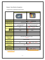
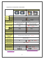
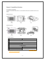
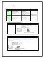
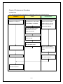
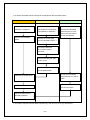
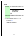
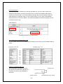
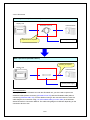
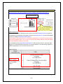
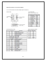
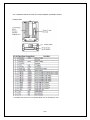
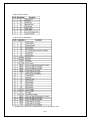
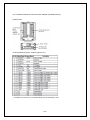
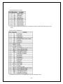
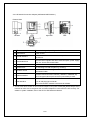
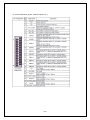
Easy! Smooth!
GP2000H Series
Replacement Guidebook
1/56
Preface
This guidebook introduces the procedures to replace the unit in the GP2000H series
(GP-2401HT, GP-2301HS/L) with the GP3000H series (GP-3310HT, GP-3300HS/L). The
recommended replacement models are as follows:
Model in use
Replacement model
GP-2401HT
GP-3310HT
GP-2301HS
GP-3300HS
GP-2301HL
GP-3300HL
About the order model number of the GP3000H Series
Emergency Switch and Key Switch are options. When ordering a GP3000H unit, please confirm
the model number.
Fourth Edition: Aug 2011
2/56
Table of Contents
PREFACE
2
ABOUT THE ORDER MODEL NUMBER OF THE GP3000H SERIES
2
CHAPTER 1. SPECIFICATION COMPARISON
5
1.1 SPECIFICATIONS OF GP-2401HT AND GP-3310HT
5
1.2 SPECIFICATIONS OF GP-2301HS/L AND GP-3300HS/L
6
CHAPTER 2. COMPATIBILITY OF HARDWARE
7
2.1 LOCATIONS OF INTERFACES
7
2.2 SCREEN SIZE
8
2.3 TOUCH PANEL SPECIFICATIONS
8
2.4 VIBRATION FUNCTION
8
2.5 FUNCTION SWITCH
8
2.6 GP-H70 COMPATIBILITY MODE
8
2.7 KEY SWITCH
8
2.8 EXTERNAL OUTPUT INTERFACE
8
2.9 BARCODE READER CONNECTION
9
2.10 SCREEN DATA TRANSFER
9
2.11 OPTIONAL PRODUCTS
9
2.12 CONNECTION TO HOST CONTROLLER
9
2.13 OVERSEAS STANDARDS
10
CHAPTER 3. REPLACEMENT PROCEDURE
11
3.1 WORK FLOW
11
3.2 PREPARATION
13
3.3 RECEIVE SCREEN DATA FROM THE GP2000H SERIES
14
3.4 CONVERT SCREEN DATA WITH THE PROJECT CONVERTER
17
3.5 DIFFERENCES OF SOFTWARE AFTER CONVERSION
23
3.6 TRANSFER SCREEN DATA TO THE GP3000H SERIES
24
CHAPTER 4. COMMUNICATION WITH DEVICE/PLC
28
4.1 DRIVER LIST
28
3/56
4.2 DIFFERENCES OF SYSTEM STRUCTURES
31
4.2.1 SYSTEM STRUCTURE BEFORE REPLACEMENT (GP2000H SERIES)
31
4.2.2 WORK FLOW OF REPLACEMENT OF GP2000H WITH GP3000H
31
4.2.2 WORK FLOW OF REPLACEMENT OF GP2000H WITH GP3000H
32
4.2.3 SYSTEM STRUCTURE AFTER REPLACEMENT (GP3000H SERIES)
33
4.2.3.1 STRUCTURE 1
33
4.2.3.2 STRUCTURE 2
34
4.2.3.3 STRUCTURE 3
35
4.2.3.4 STRUCTURE 4
36
4.2.3.5 STRUCTURE 5
37
4.2.3.6 STRUCTURE 6
40
4.3 MULTILINK CONNECTION
43
APPENDIX 1 SIGNALS OF CABLES (TO HOST, NO CONNECTOR)
44
A 1.1 GP2000H SERIES SPECIAL PURPOSE RS-232C CABLE (GP2000H-C232-3M/10M)
44
A.1.2 GP2000H SERIES SPECIAL PURPOSE RS-422 CABLE (GP2000H-C422-3M/10M)
45
A.1.3 GP3000H HARD-TYPE DIRECT-CONNECT CABLE (GP3000H-CBLH-10M) GP3000H SOFT-TYPE
DIRECT-CONNECT CABLE (GP3000H-CBLS-3M/5M/10M)
46
APPENDIX 2 INTERFACES OF CONVERSION ADAPTERS
48
A.2.1 GP-H70 RS-232C CONVERSION ADAPTER (GPH70-AP232-O)
48
A.2.2 GP-H70 RS-422 CONVERSION ADAPTER (GPH70-AP422-O)
49
A.2.3 GP2000H SERIES RS-232C CONVERSION ADAPTER (GP2000H-AP232)
50
A.2.4 GP2000H SERIES RS-422 CONVERSION ADAPTER (GP2000H-AP422)
52
A.2.5 GP3000H CONVERSION ADAPTER (AGP3000H-ADPCOM-01)
54
4/56
Chapter 1. Specification Comparison
1.1 Specifications of GP-2401HT and GP-3310HT
GP-2401HT
GP-3310HT
TFT color LCD
Display Type
256 colors
65,536 colors
VGA (640×480 pixels) → See 2.2
Display Colors
Display Resolution
External Dimensions
W253[9.96]×H185[7.28]×D58[2.28]
W224[8.82]×H174[6.85]×D87.1[3.43]
(Unit: mm [in.])
(When including the Emergency
(When including the Emergency
Switch: D76[2.99])
Switch: D107.5[4.23])
Touch Panel Type
Memory Application
SRAM
Resistive Film (Analog)
→ See 2.3
Matrix
2MB
8MB
128KB
320KB
Serial Interface
RS-232C/422
Ethernet Interface
10BASE-T
Vibration
Yes
Function Switch
15 switches
3-Position Enable
11 switches → See 2.5
→ See 2.6
Interface
Emergency Switch
Push-lock switch *1
Output Interface
Output Interface
10BASE-T/100BASE-TX
No → See 2.4
Rear panel switch 3-position output
Switch Output
Key Switch
RS-232C/422/485
No
Yes → See 2.7
External Output
Yes → See 2.8
Interface
Yes
CF Card Interface
USB Host Interface
No
Yes
Printer Interface
No
USB → See 2.8
*1: Emergency Switch is an option. For details, please refer to [About the order model number of
the GP3000H Series].
5/56
1.2 Specifications of GP-2301HS/L and GP-3300HS/L
GP-2301HS/L
GP-3300HS/L
Display
GP-****HS
STN color LCD
Type
GP-****HL
Monochrome LCD
Display
GP-****HS
64 colors
Color
GP-****HL
2 levels / 8 levels
4,096 colors
16 levels
QVGA (320×240 pixels)
Display Resolution
External Dimensions
W253[9.96]×H185[7.28]×D58[2.28]
W224[8.82]×H174[6.85]×D87.1[3.43]
(Unit: mm [in.])
(When including the Emergency
(When including the Emergency
Switch: D76[2.99])
Switch: D107.5[4.23])
Touch Panel Type
Memory Application
SRAM
Resistive film (Analog)
→ See 2.3
Matrix
1MB
6MB
128KB
320KB
Serial Interface
RS-232C/422
Ethernet Interface
No
Vibration
Yes
RS-232C/422/485
10BASE-T/100BASE-TX
No → See 2.4
11 switches
Function Switch
3-Position Enable
Switch Output
Rear panel switch 3-position output → See 2.6
Interface
Emergency Switch
Push-lock switch *1
Output Interface
Key Switch
Output Interface
No
Yes → See 2.7
External
Yes → See 2.8
Output Interface
Yes
CF Card Interface
USB Host Interface
No
Printer Interface
No
Yes
USB → See 2.8
Overseas Standards
→ See 2.13
*1: Emergency Switch is an option. For details, please refer to [About the order model number of
the GP3000H Series].
6/56
Chapter 2. Compatibility of Hardware
2.1 Locations of interfaces
Locations of connectors and switches on the GP2000H series and the GP3000H series are as
follows:
GP2000H (2401H)
Front
Rear
Top
Rear
Top
GP3000H (3310H)
Front
Interface names
GP2000H Series
GP3000H Series
1
Emergency Switch *1
2
Operation Switch
3
Function Switches
4
-
Key Switch
5
3-Position Enable Switch
6
CF Card Interface
7
Tool Connector
-
8
-
USB Host Interface
9
-
Touch Pen
*1: Emergency Switch is an option. For details, please refer to [About the order model
number of the GP3000H Series].
7/56
2.2 Screen size
The screen size of GP-3310HT, which is 5.7 inches, is smaller than that of GP-2401HT (6.5
inches). However, its display resolution is same.
Displays of texts, parts, etc. become smaller after conversion. If they are too small to touch with
your finger, please use the provided touch pen.
2.3 Touch panel specifications
The GP3000H series units are analog resistive. An analog resistive touch panel does not
recognize the touch input when you touch two points at the same time. If you applied the
two-point touch input on the GP2000H unit, we recommend you change to the one-point touch
input using the switch delay function.
2.4 Vibration function
The GP3000H series doesn’t have the vibration function. Please aware of it when converting
project data. If you use the vibration function in the GP2000H series, change it to another
function as necessary.
2.5 Function switch
The GP-2401HT has 15 function switches. However, the GP-3310HT has only 11 switches, as
the GP3000H series is designed lightweight. Please aware of it when converting project data.
2.6 GP-H70 Compatibility Mode
The GP3000H series doesn’t have the GP-H70 Compatibility Mode. The operation switch and
the 3-Position Operation Switch on the rear operate in the GP2000H Mode.
For the details of the GP2000H Mode and the GP-H70 Compatibility Mode, refer to GP2000H
Series User Manual “3.3.3 2000H Mode / GP-H70 Compatibility Mode.”
2.7 Key switch
In case of setting up an external circuit (an emergency stop circuit) using the Key switch, the
GP3000H series allows you to remove it from the conversion adapter without stopping the
system.
However, to use the Key switch, the GP3000H conversion adapter (AGP3000H-ADPCOM-01)
and the GP3000H cable with a connector (GP3000H-CBL*D-*M) are required. The Key switch
is disabled when the GP2000H conversion adapter (GP2000H-AP***) is used.
2.8 External output interface
To use the DOUT, Operation Switch Output, or External Buzzer Output, the GP3000H
Conversion Adapter (AGP3000H-ADPCOM-01) is required. These interfaces are disabled when
the GP2000H conversion adapter (GP2000H-AP***) is used.
8/56
2.9 Barcode reader connection
The GP3000H units are not equipped with a tool port. A barcode reader connected from the tool
port on the GP2000H unit cannot be used with the GP3000H. However, the GP3000H series
allows you to connect a barcode reader on its USB interface.
2.10 Screen data transfer
To transfer screen data to the GP3000H unit, use a USB or Ethernet cable to transfer screen
data. For USB transfer, use a transfer cable for the GP3000 series (model: CA3-USBCB-01).
Please note that any commercial USB cable cannot be used.
Transfer cables (GPW-CB02, GPW-CB03, GP430-CU02-M) that are used via the tool port
cannot be used with the GP3000H series.
2.11 Optional products
Optional products for the GP3000H series are different from those for the GP2000H series, other
than the neck strap (model: GP2000H-STRAP11). For the GP3000H series, prepare the
followings as necessary:
◆
Screen Protection Sheet (GP3000H-DFS6-01)
Disposable, dirt-resistant sheet for the GP unit’s screen (5 sheets/set, hard type)
◆
Wall Adapter Attachment (GP3000H-WMA-01)
Bracket for mounting the GP3000H series unit to a commercially available arm or panel.
◆
Touch Pen (CA7-TPPEN/ALL-01)
Pen for screen operation (5 pens/set, 1 pen is provided in the package.)
◆
Hand Strap (GP3000H-HS-01)
Strap for hanging GP3000H by hand (1 strap is provided in the package.)
◆
Emergency Switch Guard (GP3000H-EMGD11)
Guard for preventing accidental operation. Includes 3 mounting screws. (1 guard is provided
in the package.)
◆
Function Switch Sheet (1 set is provided in the package.)
2.12 Connection to host controller
For replacement of the GP2000H with the GP3000H, you may need to rewire. For the details,
see 4.2 Differences of system structures.
9/56
2.13 Overseas standards
The GP2000H series and GP3000H series conform to the following standards:
UL
c-UL(CSA)
GP2000H
UL60950 Third edition
CAN/CSA-C22.2
Series
(Safety Standard for
No. 60950-00
Information Technology
(Standard for Safety of
Equipment)
Information Technology
CE
Equipment)
EN55011 Class A
and EN61000-6-2
GP3000H
UL508
CAN/CSA-C22.2
Series
(Safety Standard for
No.142-M1987
Industrial Control
(c-UL approval)
Equipment) *
(Industrial Control
Equipment)
* The following system design is UL approved.
UL approved system structure using a conversion adapter
GP3000H Series
▼ The GP3000H unit in the following structure conforms to UL508:
NOTE
The system structure using a GP3000H series unit + a GP3000H cable + a GP2000
conversion adapter is not UL508 listed. If you need it UL508 approved, the application shall
be made at your end. For the detailed documents of the product, contact the nearest
Pro-face office.
10/56
Chapter 3. Replacement Procedure
3.1 Work Flow
◆ To change the equipment designed for the GP2000H series to the GP3000H series
Installation
Screen
Communication
Check the compatibility of
Check the differences of
Check the connection
hardware in Chapter 2.
specifications in the booklet
between the GP3000H
“Compatibility of Software”.
series and a PLC in the
GP-Pro EX Device/PLC
Connection Manual.
Convert GP2000H screen
data with GP-Pro EX’s
Project Converter.
Check and modify the data
in GP-Pro EX.
Transfer the screen data to
the GP3000H series.
Install the GP3000H series.
Connect the GP3000H
series and the PLC with a
cable.
Connect the power cord.
Start connection and check
the communication.
Check the performance
and start operation.
11/56
◆ To replace the 2000H series mounted to the equipment with the 3000H series
Installation
Screen
Communication
Check the compatibility of
Check the differences of
Check the connection
hardware in Chapter 2.
specifications in the booklet
between the GP3000H
“Compatibility of Software”.
series and a PLC in the
GP-Pro EX Device/PLC
Remove the GP2000H
series.
Connection Manual.
Receive the screen data
from the GP2000H series. *1
Convert the data with
GP-Pro EX’s Project
Converter.
Check and modify the data
in GP-Pro EX.
Transfer the screen data to
the GP3000H series.
Connect the GP3000H
Install the GP3000H series.
series and the PLC with a
cable.
Start connection and check
Connect the power cord.
the communication.
Check the performance
and start operation.
*1 This step is required if screen data is saved only in the GP unit, not in any other device.
12/56
3.2 Preparation
Requirements for
PC in which GP-PRO/PB3 for Windows V.6.01 or later is installed
receiving screen data
Note: The software version must be the same or higher than the
from the GP2000H
version that you used when creating screen data for the
series *1
GP2000H series. We recommend you upgrade to the latest
version, which is Ver. 7.29 as of June 2009.
Transfer cable (the following three types of cable are available)
▪
GPW-CB02 (9-pin D-sub to the PC)
▪
GPW-CB03 (USB to the PC) (*2)
▪
GP430-CU02-M or GPW-SET
The GP2000H series also allows you to transfer screen data via a
CF card.
Requirements for
PC in which GP-Pro EX is installed
converting screen data Transfer cable (model: CA3-USBCB-01)
of the GP2000H series The GP3000H series also allows you to transfer screen data via
and transferring to the
an Ethernet cable, CF card, or USB flash drive.
3000H series
*1: This step is required if screen data is saved only in the GP unit, not in any other device.
*2: GPW-CB03 is compliant with GP-PRO/PB3 for Windows C-Package02 SP2 Ver. 6.23 or later.
To use it, you may need to install the driver.
Go to our support website Otasuke Pro!
-> Download
-> Updates/Drivers
-> GP-PRO/PB3: USB Data Transfer Cable (GPW-CB03)
13/56
3.3 Receive screen data from the GP2000H series
This section explains, as an example, how to receive screen data from the GP unit using a
transfer cable GPW-CB02 or GPW-CB03. If you have backed up screen data, this step is
unnecessary; slip to the next section “3.4 Convert screen data with the Project Converter.”
1. Connect a transfer cable to the GP2000H series.
2. Start up GP-PRO/PB3 C-Package and click the [Transfer] icon on the Project Manager.
(Specify a desired project file.)
3. On the [Transfer] window, select the [Setup] menu and click [Transfer Settings…].
14/56
4. In the Communication Port field, select [COM], specify the COM port to which the cable is
connected, and click [OK].
If you use a USB transfer cable (GPW-CB03)…
You can check the COM port for the USB transfer cable (GPW-CB03), which is
assigned to the PC with the Device Manager of Windows.
15/56
5. Select the [Transfer] menu and click [Receive…].
6. Specify the location to save the received screen data in and the project file name and save.
In case there is no Upload Information…
“Upload Information” is necessary to receive screen data from the display unit. It needs to
be included in screen data when transferring screen data to the display unit beforehand.
The Upload Information is sent to the display unit by default, however, you may check off
the box of Upload Information to prevent screen reception by a third party.
In this case, a message, which indicates there is no Upload Information,” appears and you
cannot receive the data.
You can check if the Upload Information has been sent or not in the following way.
Enter into the GP’s Offline mode. If there are 2 asterisk (*) marks in the Main menu as
below, the Upload Information has been sent. If not, there is no Upload Information sent.
16/56
3.4 Convert screen data with the Project Converter
Convert a project file (*.prw) for the GP-37W2 unit with the GP-Pro EX’s Project Converter.
1. Click the [Start] button, select the [All Programs] ([Programs] on Windows® 2000 menu →
[Pro-face] → [GP-Pro EX*.**]. (Where *.** is the version of the software you use.)
2. The Project Converter starts up and the [Project Converter] dialog box opens. Select [Project
File (*.PRW)] in the [Data Type].
3. Designate a GP-PRO/PB3 for Windows’ project file (*.prw) in [Convert-From].
Click the [Browse…] button and select a project file (e.g.: “Project system A.prw”). Click
[Open], and the file will be set in [Convert-From].
17/56
4.
In [Convert-To], designate a GP-Pro EX’s project file (*.prx). Click the [Browse…] button and
enter a new [File Name] (e.g.: “Product system A.prx”). Click [Save], and a new project file
will be set to [Convert-To].
18/56
NOTE
z
When a convert-to file exists, the window that confirms whether or not to
overwrite the file is displayed.
19/56
5.
Click [Convert] and start the conversion.
20/56
NOTE
•
Depending on the model you are converting from, the [Convert Destination] dialog
box may appear and you can select the type and the model.
•
If the following dialog box appears, set a CF card output folder.
→ See the next page
Convert GP-PRO/PB3 for Windows’ “Destination CF Card Folder”
6.
After conversion, the [Save convert information] dialog box appears. If you click [Save], you
can save the conversion information in a text file.
7.
Click [Close] to close the [Project Converter] dialog box.
21/56
◆ Convert GP-PRO/PB3 for Windows’ “Destination CF Card Folder”
If you convert a project file (*.prw) with a destination CF card folder designated in the step 5, the
Question dialog box asking whether or not to designate the destination CF card folder for the
convert destination appears again.
Select a folder (e.g.: “Database”) and click [OK].
If you click the [Make New Folder] button, you can create a new folder at any location.
IMPORTANT
In the [Question] dialog box, be sure to select [Yes] and specify the destination folder. If
you select [No], images will not be called correctly.
22/56
3.5 Differences of software after conversion
Check the differences of screen data after conversion.
For the details of each item, refer to the booklet “Compatibility of Software” or visit out website.
http://www.pro-face.com/otasuke/qa/gp3000/replace/soft.htm
Touch Panel Type
1
2
Compatibility of Bit Switch
3
Compatibility of Trend Graph
4
Compatibility of K Tag (Input Order)
5
Compatibility of K Tag (Difference of Writing)
6
Compatibility of K Tag (Indirect Setting)
7
Compatibility of N Tag
8
About the performance when a window is overlapping on a momentary switch
9
About the performance when display area of the system window is overlapping
10
Change of Tag Process
11
Compatibility of Text
12
Compatibility of Fill
13
Compatibility of CF Card Data
14
Precautions for conversion when filing data is saved in a CF card
15
Precautions for setting “Color Settings” to [256 Colors without blinking]
16
Precautions for loading a part with “L Tag (Library Display)”
17
Compatibility of MRK files and CPW files
18
Compatibility of VM Unit Settings
19
Compatibility of Extended SIO Script
20
Compatibility of Sound Data
21
Compatibility of Device Monitor
22
Compatibility of J Tag and R Tag
23
DOS Screen Data Conversion
24
Compatibility of Standard Fonts
25
Compatibility of D-Script Trigger Conditions ( D-Script runs immediately after the
screen is changed or the power is turned on )
26
Compatibility of U Tag ( Window Screen is positioned in an unexpected area when
called )
27
Precausion for Conversion when Screen Level Change is configured
28
Precausion for Use of Project Converter
29
Compatibility of LS Area
30
Compatibility of L Tag
23/56
3.6 Transfer screen data to the GP3000H series
Transfer the converted project file to the GP3000H unit. Although you can transfer data to the
GP3000H unit via a USB flash drive, this section explains, as an example, how to transfer screen
data with a USB transfer cable (model: CA3-USBCB-01).
1. Connect your PC and the GP3000H series with a USB transfer cable. If the driver of the
cable has not been installed on your PC yet, a dialog box will appear. Please follow the
instructions.
NOTE
The “Hardware Installation” dialog box as follows may appear during installing the driver
of a USB depending on the security level of Windows XP. Click [Continue Anyway] to
start installing the driver for CA3-USBCB-01. When installation is completed, click
[Finish].
24/56
2. Turn on the display unit’s power. The “Initial Start Mode” screen will appear on the
display unit.
This screen will appear when
you first connect the display
unit’s
power
code.
After
transferring a project file once,
this screen will not appear
again.
3. On the GP-Pro EX’s State Toolbar, click the [Transfer Project] icon to open the Transfer
Tool.
4. Check the project file name and other data to be transferred in the Project Information.
To transfer a different project file, click the [Select Project] button and select a project file.
25/56
5. Make sure that the [Device] in the “Transfer Information” is set to [USB]. If not, click the
[Transfer Setting] button to open the “Transfer Settings” dialog box. Select [USB] in the
Communication Port Settings field and click [OK].
6. Click [Send Project] to start transfer. When the following dialog box appears, click [Yes].
This dialog box doesn’t appear when the same project file is sent again.
26/56
7. The following dialog box appears during transfer and you can check the communication
status. (The display unit enters the Transferring mode and communication with the
device such as a PLC is terminated.)
Display Screen
8. When transfer is completed, the status displayed in the dialog box will change from
[Transferring] to [Complete Transfer]. Click [Close] to close the dialog box. (The display
unit will be reset and a screen of the transferred project file will be displayed.)
9. Close the Transfer Tool.
27/56
Chapter 4. Communication with Device/PLC
4.1 Driver list
IMPORTANT
The followings are information as of May 2009.
More connectable drivers will be added. Please check our website “Otasuke Pro!” for the latest
information.
PLC
Manufacturer
Series
GP3000H
A Series CPU Direct
✔
A Series Ethernet
✔
A Series Computer Link
✔
FX Series CPU Direct
✔
FX Series Computer Link
✔
Q Series CPU Direct
✔
Q/QnA Serial Communication
✔
Q/QnA Series Ethernet
✔
QnA Series CPU Direct
✔
QUTE Series CPU Direct
✔
Q Series QnU CPU Ethernet
✔
C/CV Series HOST Link
✔
CS/CJ Series HOST Link
✔
CS/CJ Series Ethernet
✔
MEMOBUS SIO
✔
MEMOBUS Ethernet
✔
MP Series SIO (Extension)
✔
MP Series Ethernet (Extension)
✔
H Series SIO
✔
H Series Ethernet
✔
FP Series Computer Link SIO
✔
Personal Computer Link SIO
✔
Personal Computer Link Ethernet
✔
JTEKT Corporation
TOYOPUC CMP-LINK SIO
✔
(Formerly Toyoda Machine Works)
TOYOPUC CMP-LINK Ethernet
✔
Fuji Electric Co., Ltd.
MICREX-F Series SIO
✔
MICREX-SX Series SIO
✔
MICREX-SX Series Ethernet
✔
Series 90 Ethernet
✔
Mitsubishi Electric Corporation
OMRON Corporation
YASKAWA Electric Corporation
Hitachi IES Co., Ltd.
Panasonic Electric Works, Ltd.
(Formerly Matsushita Electric Works, Ltd.)
YOKOGAWA Electric Corporation
GE Fanuc Automation
28/56
Series 90-30/70 SNP
✔
Series 90-30/70 SNP-X
✔
FUNUC Ltd
Power Mate Series
✔
Siemens AG
SIMATIC S7 MPI Direct
✔
SIMATIC S7 3964(R)/RK512
✔
SIMATIC S7 Ethernet
✔
SIMATIC S5 CPU Direct
✔
DF1
✔
EtherNet/IP
✔
DH-485
✔
KV-700/1000/3000/5000 CPU Direct
✔
KV-700/1000/3000/5000 Ethernet
✔
KV Series CPU Direct
✔
KZ10_80R/Tseries CPU Direct
✔
MODBUS SIO Master
✔
MODBUS TCP Master
✔
Uni-Telway
✔
MODBUS Slave
✔
JW Series Computer Link SIO
✔
JW Series Computer Link Ethernet
✔
MASTER-K Series Cnet
✔
XGT Series FEnet
✔
XGT Series Cnet
✔
DIASYS Netmation MODBUS TCP
✔
MHI STEP3 Ethernet
✔
Saia-Burgess Controls Ltd.
SAIA S-Bus SIO
✔
MEIDENSHA Corporation
UNISEQUE Series Ethernet
✔
Hitachi, Ltd.
S10V Series Ethernet
✔
S10 Series SIO
✔
TOSHIBA Machine Co., Ltd.
TCmini/TC200
✔
TOSHIBA Corporation
Computer Link SIO
✔
Computer Link Ethernet
✔
KOSTAC/DL Series CCM SIO
✔
KOSTAC/DL Series MODBUS TCP
✔
FB Series SIO
✔
Rockwell Automation, Inc.
KEYENCE Corporation
Schneider Electric Industries
SHARP MS Corporation
LS Industrial System
Mitsubishi Heavy Industries, Ltd.
Koyo Electronics Co., Ltd.
FATEK AUTOMATION Corporation
29/56
Temperature Controller
Manufacturer
Series
GP3000H
Yamatake Corporation
Digital Controller SIO
✔
RKC Instrument Inc.
Temp. Controller MODBUS SIO
✔
Temperature Controller
✔
OMRON Corporation
Temp. Controller CompoWay/F
✔
Shinko Technos Co., Ltd.
Controller SIO
✔
YOKOGAWA Electric Corporation
Personal Computer Link SIO
✔
CHINO Corporation
Temp. Controller MODBUS SIO
✔
Fuji Electric Systems Co., Ltd.
Temp. Controller MODBUS SIO
✔
Inverter/Servo
Manufacturer
Series
GP3000H
Mitsubishi Electric Corporation
FREQROL Inverter
✔
YASKAWA Electric Corporation
Inverter SIO
✔
Hitachi IES Co., Ltd.
Inverter ASCII SIO
✔
InverterModbus RTU
✔
Si/CutyAxisSeries SIO
✔
Sanmei Electric Co., Ltd.
Industrial Robot
Manufacturer
Series
GP3000H
Hyundai Heavy Industries
Hi4 Robot
✔
IAI Corporation
ROBO CYLINDER MODBUS SIO
✔
X-SEL Controller
✔
Other Devices
Manufacturer
Digital Electronics Corporation
MODBUS IDA
Series
GP3000H
Memory Link *1
✔
General SIO *2
✔
General Ethernet *2
✔
General Modbus SIO Master
✔
General Modbus TCP Master
✔
*1: The product doesn’t need to choose a host controller like PC, Microcomputer board, etc. It
communicates via the storage space built into the main unit
*2: A program driver for the send/receive command process by D-Script.
30/56
4.2 Differences of system structures
4.2.1 System structure before replacement (GP2000H Series)
The following system structure is one of the typical structures for the connection of the GP2000H
series:
Display Unit
A
GP2000H
Check the model type of adapter in use.
•
GP2000H-AP232
•
GP2000H-AP422
•
GPH70-AP232-O
•
GPH70-AP422-O
•
Self-created cable or established
terminal block
Board
External device
24VDC power supply
B
Check the model type of Pro-face cable
connecting with the GP2000H series.
●
GP2000H-D232-*M (D-sub type)
●
GP2000H-D422-*M (D-sub type)
●
GP2000H-AP70CB-D232-3M
●
GP2000H-AP70CB-D422-3M
●
GP2000H-C232-*M (Breakout type)
●
GP2000H-C422-*M (Breakout type)
Where * is the length (m) of cable.
31/56
4.2.2 Work flow of replacement of GP2000H with GP3000H
What is the model of cable connecting the
GP2000H and the conversion adapter?
1) GP2000H-D***-*M
If none of them, contact the
or
nearest Pro-face office or your
GP2000H-AP70CB-D***-3M
local distributor.
2) GP2000H-C232-*M
3) GP2000H-C422-*M
②
①
③
What is the model of conversion adapter?
1) GP2000H-AP232
2) GP2000H-AP422
3) GPH70-AP232-O
4) GPH70-AP422-O
①
②
③
④
See
See
See
See
See
See
4.2.3.1
4.2.3.2
4.2.3.3
4.2.3.4
4.2.3.5
4.2.3.6
NOTE
Where *** in the model name is the communication method and * is the length of the cable.
32/56
4.2.3 System structure after replacement (GP3000H Series)
4.2.3.1 Structure 1
Before replacement (GP2000H Series)
24V DC power supply
Display Unit
GP410-IS00-O or
External Device
self-created cable
GP2000H-D232-*M
GP2000H
GP2000H-AP232
Replacement is required.
After replacement (GP3000H Series)
24V DC power supply
Display Unit
GP410-IS00-O or
GP3000H-
External Device
self-created cable
CBLSD232-*M
GP3000H
GP2000H-AP232
About replacement
When you replace the GP2000H unit with the GP3000H unit, you also need to replace the
GP2000H cable (GP2000H-D232-*M) with the GP3000H cable (GP3000H-CBLSD232-*M).
However, you can use the GP2000H conversion adapter (GP2000H-AP232) and the cable
GP410-IS00-O or self-created cable without changing.
If you use GP2000H-AP232 to connect the GP3000H, some features are restricted. For the
details, see A.1.3 “IMPORTANT.”
33/56
4.2.3.2 Structure 2
Before replacement (GP2000H Series)
24V DC power supply
Display Unit
Self-created cable
GP2000H-D422-*M
External Device
GP2000H
GP2000H-AP422
Replacement is required.
After replacement (GP3000H Series)
24V DC power supply
Display Unit
External Device
GP3000HSelf-created cable
CBLSD422-*M
GP3000H
GP2000H-AP422
About replacement
When you replace the GP2000H unit with the GP3000H unit, you also need to replace the
GP2000H cable (GP2000H-D422-*M) with the GP3000H cable (GP3000H-CBLSD422-*M).
However, you can use the GP2000H conversion adapter (GP2000H-AP422) and the self-created
cable without changing.
If you use GP2000H-AP422 to connect the GP3000H, some features are restricted. For the
details, see A.1.3 “IMPORTANT.”
34/56
4.2.3.3 Structure 3
Before replacement (GP2000H Series)
24V DC power supply
Display Unit
GP2000H-AP70CB-
GP410-IS00-O or
D232-3M
self-created cable
External Device
GP2000H
GPH70-AP232-O
Replacement is required.
After replacement (GP3000H Series)
24V DC power supply
Display Unit
GP3000H-
GP410-IS00-O or
CBLSD232-*M
self-created cable
External Device
GP3000H
GP2000H-AP232
About replacement
When you replace the GP2000H unit with the GP3000H unit, you also need to replace the
GP2000H series GP-H70 conversion adapter connection cable (GP2000H-AP70CB-D232-3M)
with the GP3000H cable (GP3000H-CBLSD232-*M), and the GP-H70 conversion adapter
(GPH70-AP232-O) with the GP2000H conversion adapter (GP2000H-AP232). However, you can
use the cable GP410-IS00-O or self-created cable without changing.
If you use GP2000H-AP232 to connect the GP3000H, some features are restricted. For the
details, see A.1.3 “IMPORTANT.”
35/56
4.2.3.4 Structure 4
Before replacement (GP2000H Series)
24V DC power supply
Display Unit
GP2000H-AP70CBSelf-created cable
D422-3M
External Device
GP2000H
GPH70-AP422-O
Replacement is required.
After replacement (GP3000H Series)
24V DC power supply
Display Unit
GP3000H-
Self-created cable
CBLSD422-*M
External Device
GP3000H
GP2000H-AP422
About replacement
When you replace the GP2000H unit with the GP3000H unit, you also need to replace the
GP2000H series GP-H70 conversion adapter connection cable (GP2000H-AP70CB-D422-3M)
with the GP3000H cable (GP3000H-CBLSD422-*M), and the GP-H70 conversion adapter
(GPH70-AP422-O) with the GP2000H conversion adapter (GP2000H-AP422). However, you can
use the self-created cable without changing.
If you use GP2000H-AP422 to connect the GP3000H, some features are restricted. For the
details, see A.1.3 “IMPORTANT.”
36/56
4.2.3.5 Structure 5
Before replacement (GP2000H Series)
Display Unit
GP2000H-C232-*M
External Device
GP2000H
24V DC power supply
Replacement is required.
After replacement (GP3000H Series)
Rewiring is required.
Display Unit
External Device
GP3000H-CBL*-*M
GP3000H
24V DC power supply
37/56
About replacement
When you replace the GP2000H unit with the GP3000H unit, you also need to replace the
GP2000H cable (without connector) (GP2000H-C232-*M) with the GP3000H cable (without
connector) (GP3000H-CBL*-*M). For the details of wiring to the connection device, check the
cable diagram for connection using your self-created cable (your own cable) in the GP3000
Series Device/PLC Connection Manual. The cable-wiring diagram is different depending on the
connection device to use.
Cable diagram 1
Example of Device/PLC Connection Manual
About cable color and identification mark
The wire jacket colors of the GP2000H cable are different from those of the GP3000H cable as
follows:
Example of GP3000H-CBL*-*M
In the right figure, the jacket color of the
wire is brown and two black marks are on it.
Therefore, this wire can be identified as
RS (RTS).
38/56
NOTE
System structure using the GP3000H conversion adapter (AGP3000H-ADPCOM-01)
24V DC power supply
Display Unit
Established cable or
GP3000H-CBL*D-*M
self-created cable
External Device
GP3000H
AGP3000H-
If you use the self-created
ADPCOM-01
cable, rewiring is required.
About replacement
You can also replace the GP2000H cable (without connector) (GP2000H-C232-*M) with the
combination of the GP3000H cable (with connector) (GP3000H-CBL*D-*M) and the GP3000H
conversion adapter (AGP3000H-ADPCOM-01).
As the shape of the serial interface on AGP3000H-ADPCOM-01 is same as that of the COM1
port of the GP3000H series, you can use not only the self-created cable (B in the table below)
but also established cable (A in the table).
For the details of wiring AGP3000H-ADPCOM-01 to the connection device, check the cable
diagram in the GP3000 Series Device/PLC Connection Manual. The cable-wiring diagram is
different depending on the connection device to use.
Cable diagram 1
Example of Device/PLC Connection Manual
39/56
4.2.3.6 Structure 6
Before replacement (GP2000H Series)
Display Unit
GP2000H-C422-*M
External Device
GP2000H
24V DC power supply
Replacement is required.
After replacement (GP3000H Series)
Rewiring is required.
Display Unit
GP3000H-CBL*-*M
External Device
GP3000H
24V DC power supply
About replacement
When you replace the GP2000H unit with the GP3000H unit, you also need to replace the
GP2000H cable (without connector) (GP2000H-C422-*M) with the GP3000H cable (without
connector) (GP3000H-CBL*-*M). For the details of wiring to the connection device, check the
cable diagram for connection using your self-created cable (your own cable) in the GP3000
Series Device/PLC Connection Manual. The cable-wiring diagram is different depending on the
connection device to use.
40/56
Cable diagram 2
Example of Device/PLC Connection Manual
About cable color and identification mark
The wire jacket colors of the GP2000H cable are different from those of the GP3000H cable as
follows:
Example of GP3000H-CBL*-*M
In the right figure, the jacket color of the
wire is brown and two black marks are on it.
Therefore, this wire can be identified as
SDB.
41/56
NOTE
System structure using the GP3000H conversion adapter (AGP3000H-ADPCOM-01)
24V DC power supply
Display Unit
Established cable or
GP3000H-CBL*D-*M
self-created cable
External Device
GP3000H
AGP3000H-ADPCOM-01
If you use the self-created
cable, rewiring is required.
About replacement
You can also replace the GP2000H cable (without connector) (GP2000H-C422-*M) with the
combination of the GP3000H cable (with connector) (GP3000H-CBL*D-*M) and the GP3000H
conversion adapter (AGP3000H-ADPCOM-01).
As the shape of the serial interface on AGP3000H-ADPCOM-01 is same as that of the COM1
port of the GP3000H series, you can use not only the self-created cable (B in the table below)
but also established cable (A in the table).
For the details of wiring AGP3000H-ADPCOM-01 to the connection device, check the cable
diagram in the GP3000 Series Device/PLC Connection Manual. The cable-wiring diagram is
different depending on the connection device to use.
Cable diagram 2
Example of Device/PLC Connection Manual
42/56
4.3 Multilink Connection
There are some communication drivers that do not support multi-link connection (n:1) with
RS-422 in GP3000 Series.
When converting the project file with the communication driver that multi-link connection (n:1)
with RS-422 is not supported, it will be automatically converted to (1:1) connection.
[Which drivers support serial multilink communication? ]
(http://www.pro-face.com/otasuke/files/manual/gpproex/new/device/com_mlnk.htm )
43/56
Appendix 1 Signals of Cables (to Host, no connector)
A 1.1 GP2000H Series Special Purpose RS-232C Cable (GP2000H-C232-3M/10M)
*1: External Device I/F lines #1 and #3 are reserved. Be sure not to connect anything to these lines.
*2: The DOUT Ground is used in common with External Buzzer Output (BUZZ OUT), DOUT 0 (zero) Output
(DOUT0.C), and DOUT 1 (one) Output (DOUT1.C).
*3: Disabled when the GP-H70 Compatible Mode (set via GP2000H) is used.
*4: When connected to the GP2000H, the power used should be a maximum of 0.25A. Be sure not to
exceed this level.
44/56
A.1.2 GP2000H Series Special Purpose RS-422 Cable (GP2000H-C422-3M/10M)
*1: External Device I/F lines #1 and #3 are reserved. Be sure not to connect anything to these lines.
*2: The DOUT Ground is used in common with External Buzzer Output (BUZZ OUT), DOUT 0 (zero) Output
(DOUT0.C), and DOUT 1 (one) Output (DOUT1.C).
*3: Disabled when the GP-H70 Compatible Mode (set via GP2000H) is used.
*4: When connected to the GP2000H, the power used should be a maximum of 0.25A. Be sure not to
exceed this level.
45/56
A.1.3 GP3000H Hard-type Direct-connect Cable (GP3000H-CBLH-10M)
GP3000H Soft-type Direct-connect Cable (GP3000H-CBLS-3M/5M/10M)
Serial Interface
Wire Color /
RS232C
RS422/RS485
Marking Color, Number Signal
Brown / White 1
CD
Description
Signal
Description
Carrier Detect
RDA
Receive Data A (+)
Brown / Black 1
RD (RXD)
Receive Data
RDB
Receive Data B (-)
Brown / White 2
SD (TXD)
Send Data
SDA
Send Data A (+)
Brown / White 4
ER (DTR)
Data Terminal Ready
ERA
Data Terminal Ready A (+)
Brown / None
SG
Signal Ground
SG
Signal Ground
Brown / Black 3
DR (DSR)
Data Set Ready
CSB
Clear to Send B (-)
Brown / Black 2
RS (RTS)
Request to Send
SDB
Send Data B (-)
Brown / White 3
Brown / Black 4
Green / None
CS (CTS)
Clear to Send
CSA
Clear to Send A (+)
CI (RI) /
Called status display
ERB
Data Terminal Ready B (-)
FG *2
Frame Ground
VCC
+5V ±5% Output 0.25A *1
FG *2
Frame Ground
(Common with SG)
(Common with SG)
*1: The RI/VCC selection is switched via software. The VCC output is not protected against overcurrent. To
prevent damage or unit malfunctions, use only the rated current.
*2: Select the AWG22 cable to use out of two green cables. Be sure to twist wires from a part close to the
power supply.
Ethernet Interface
Ethernet (IEEE802.3u, 10BASE-T/100BASE-TX) with modular jack connector (RJ-45)
Wire Color
Signal
Direction
Description
Blue
TX +
Output
Ethernet Send (+)
White
TX -
Output
Ethernet Send (-)
Brown
RX +
Input
Ethernet Receive (+)
Gray
RX -
Input
Ethernet Receive (-)
Wire Color
Signal
Direction
Description
Red
DC24V
Input
Power Input 24V DC
Black
0V
Input
DC24V Interface
Green
FG *1
Power Input 0V
-
Frame Ground
(Common with SG)
*1: Select the AWG16 cable to use out of two green cables. Be sure to twist wires from a part close to the
power supply.
46/56
3-Position Enable Switch Output Interface
Wire Color /
Signal
Marking Color, Number Name
Blue / Black2
ENB0A
Blue / Black3
ENB0B
Blue / None
ENB1A
Blue / Black1
ENB1B
Description
0A (a-contact)
Rating: 30V DC, 700mA (min. applicable load: 3V DC, 5mA)
0B (a-contact)
1A (a-contact)
Rating: 30V DC, 700mA (min. applicable load: 3V DC, 5mA)
1B (a-contact)
Emergency Switch Output Interface
Wire Color /
Signal
Marking Color, Number Name
Purple / Black 2
EMG0A
Purple / White 3
EMG0B
Purple / Black 1
EMG1A
Purple / White 2
EMG1B
Purple / None
EMG2A
Purple / White 1
EMG2B
Description
0A (a-contact)
Rating: 30V DC, 1A (min. applicable load: 5V DC, 1mA)
0B (a-contact)
1A (b-contact)
Rating: 30V DC, 1A (min. applicable load: 5V DC, 1mA)
1B (b-contact)
2A (b-contact)
Rating: 30V DC, 1A (min. applicable load: 5V DC, 1mA)
2B (b-contact)
Key Switch Output Interface
Wire Color /
Signal
Marking Color, Number Name
Description
Orange / None
KEY_NC
b-contact (normally closed) Rating: 24V DC, 300mA
Orange / Black 1
KEY_NO
a-contact (normally open) Rating: 24V DC, 300mA
IMPORTANT
External Output Interface
To use the DOUT, Operation Switch Output, or External Buzzer Output, the GP3000H
Conversion Adapter (AGP3000H-ADPCOM-01) is required.
<Connection to GP3000H>
Insert the cable plug to the GP3000H series
cable socket until it clicks. To remove it, unlock.
47/56
Appendix 2 Interfaces of Conversion Adapters
A.2.1 GP-H70 RS-232C Conversion Adapter (GPH70-AP232-O)
External View
14-terminals Block
(power, external outputs, etc.)
D-sub Connector (to GP)
D-sub Connector (to Host)
48/56
A.2.2 GP-H70 RS-422 Conversion Adapter (GPH70-AP422-O)
External View
14-terminals Block
(power, external outputs, etc.)
D-sub Connector (to GP)
7-terminals Block (to Host)
*1: In this adapter, pins #5, #14, #17, and #19 have been connected.
49/56
A.2.3 GP2000H Series RS-232C Conversion Adapter (GP2000H-AP232)
External View
22-terminals Block (power, external outputs, etc.)
*1: Disabled when the GP-H70 Compatible Mode (set via GP2000H) is used.
50/56
25-pin D-sub (to Host)
37-pin D-sub (to GP2000H)
*1: Disabled when the GP-H70 Compatible Mode (set via GP2000H) is used.
51/56
A.2.4 GP2000H Series RS-422 Conversion Adapter (GP2000H-AP422)
External View
22-terminals Block (power, external outputs, etc.)
*1: Disabled when the GP-H70 Compatible Mode (set via GP2000H) is used.
52/56
10-terminals Block (to Host)
*1: Pins #7 (CSA), #8 (ERA), #9 (CSB), and #10 (ERB) are shorted together with shorting clips at the
factory.
37-pin D-sub (to GP2000H)
*1: Disabled when the GP-H70 Compatible Mode (set via GP2000H) is used.
53/56
A.2.5 GP3000H Conversion Adapter (AGP3000H-ADPCOM-01)
External View
A LED
The color changes depending on the GP’s status.
B Power Switch
I: ON, O:OFF
C External Interface
D 24-terminals block
Connect the GP3000H Conversion Adapter Connection Cable to
the GP unit.
Connect DOUT signals and other external outputs, power supply
lines, etc. Use a self-created cable.
E Rotary Switch
Sets the ID number for this adapter. *1
F DIN Rail Hook
For mounting to a DIN rail (35mm [1.38 inch])
G Connector Cover
H Ethernet Interface
Remove when connecting the GP3000H Conversion Adapter
Connection Cable.
The Ethernet transmission interface (10BASE-T/100BASE-TX).
An RJ-45 type modular jack connector (8-terminals) is used.
RS232C/RS422/RS485 serial interface
I Serial Interface
9-pin D-sub plug type connecter
The communication method is switched via software.
*1: The GP stores the ID number for the conversion adapter in the system variable [#H_MachineNo] at fixed
intervals to make sure it recognizes the conversion adapter is connected to the GP correctly. For
details on system variables, refer to the GP-Pro EX Reference Manual.
54/56
D: 24-terminals Block (power, external outputs, etc.)
55/56
I: Serial Interface
Communication method:
RS232C/RS422/RS485
Asynchronous communication method
Data length:
7 bit / 8 bit
Parity:
Odd / Even / None
Stop bit:
1 bit / 2 bit
Baud rate:
2400bps to 115.2kbps, 187.5kbps(MPI)
Max. communication distance: 15m (RS-232C), 1200m (RS-422, 115.2kbps)
(Includes length of the cable between the GP and this
adapter)
*1: The RI/VCC selection for the pin #9 is switched via software. The VCC output is not protected against
overcurrent. To prevent damage or unit malfunctions, use only the rated current.
56/56