1
User's Manual
SRP-275II
Impact Printer
Rev. 1.00
http://www.bixolon.com
SRP-275II
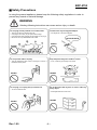
■ Safety Precautions
In using the present appliance, please keep the following safety regulations in order to
prevent any hazard or material damage.
WARNING
Violating following instructions can cause serious injury or death.
Do not plug several products in one multi-outlet.
•
•
•
•
You must use only the supplied adapter.
This can provoke over-heating and a fire.
If the plug is wet or dirty, dry or wipe it before usage.
If the plug does not fit perfectly with the outlet, do not plug in.
Be sure to use only standardized multi-outlets.
• It is dangerous to use other adapters.
ONLY SUPPLIED ADAPTER
PROHIBIT
PROHIBIT
Do not pull the cable to unplug.
Keep the plastic bag out of children’s reach.
• This can damage the cable, which is the origin of a fire or a
breakdown of the printer.
• If not, a child may put the bag on his head.
PROHIBIT
Do not plug in or unplug with your hands wet.
• You can be electrocuted.
PROHIBIT
Do not bend the cable by force or leave it under any
heavy object.
• A damaged cable can cause a fire.
PROHIBIT
PROHIBIT
Rev. 1.00
-2-
SRP-275II
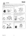
CAUTION
Violating following instructions can cause slight wound or damage the appliance.
If you observe a strange smoke, odor or noise from
the printer, unplug it before taking following
measures.
Keep the desiccant out of children’s reach.
• If not, they may eat it.
• Switch off the printer and unplug the set from the mains.
• After the disappearance of the smoke, call your dealer to
repair it.
TO UNPLUG
PROHIBIT
PRINTER
Install the printer on the stable surface.
• If the printer falls down, it can be broken and you can hurt
yourself.
Use only approved accessories and do not try to
disassemble, repair or remodel it for yourself.
• Call your dealer when you need these services.
• Do not touch the blade of auto cutter.
PRINTER
DISASSEMBLING
PROHIBITED
PROHIBIT
PRINTER
Do not let water or other foreign objects in the
printer.
Do not use the printer when it is out of order. This
can cause a fire or an electrocution.
• If this happened, switch off and unplug the printer before
calling your dealer.
• Switch off and unplug the printer before calling your dealer.
PROHIBIT
TO UNPLUG
PRINTER
PRINTER
DEALER
Rev. 1.00
-3-
SRP-275II
All rights reserved. No part of this publication may reproduced, stored in a retrieval, or
transmitted in any form or by any means, electronic, mechanical, photocopying, recording,
or otherwise, without the prior written permission of BIXOLON.
No patent liability is assumed with respect to the use of the information contained herein.
While every precaution has been taken in the preparation of this book, BIXOLON assumed
no responsibility for errors or omissions. Neither is any liability assumed for damages
resulting from the use of the information contained herein.
Neither BIXOLON nor its affiliates shall be liable to the purchaser of this product or third
parties for damages, losses, costs, or expenses incurred by purchaser or third parties as a
result of : accident, misuse, or abuse of this product or unauthorized modifications, repairs,
or alterations to this product, or (excluding the U.S.) failure to strictly comply with
BIXOLON s operating and maintenance instructions.
BIXOLON shall not be liable against any damages or problems arising from the use of any
options or ant consumable products other than those designated as Original BIXOLON
products.
■ Notice
We at BIXOLON maintain ongoing efforts to enhance and upgrade the functions and
quality of all our products. In following, product specifications and/or user manual content
may be changed without prior notice.
Rev. 1.00
-4-
SRP-275II
■ EMC and Safety standards Applied
Product Name : SRP-275II
The following standards are applied only to the printers that are so labeled.
Europe :
CE marking, TUV/GS : EN60950-1; 2001
North America :
EMI : FCC Class A
Safety standards :
UL / C-UL : UL60950-1
National : CB-scheme : IEC 60950-1: 2001
■ WARNING
The connection of a non-shielded printer interface cable to this printer will invalidate the
EMC standards of this device. You are cautioned that changes or modifications not
expressly approved by the party responsible for compliance could void your authority to
operate the equipment.
■ CE Marking
The printer conforms to the following Directive and Norms
EMC Directive 89/336/EEC
EN55022 Class A : 1998+A1 : 2000
EN55024 : 1998:+A1 : 2001
EN61000-3-2 : 2000
EN61000-3-3 : 1995+A1 : 2001
Low Voltage Directive 73/23/EEC
Safety : EN60950-1 : 2001
■ Waste Electrical and Electric Equipment (WEEE)
This marking shown on the product or its literature, indicates that is should not
be disposed with other household wastes at the end of its working life, To
prevent possible harm to the environment or human health from uncontrolled
waste disposal, please separate this from other types of wastes and recycle it
responsibly to promote the sustainable reuse of material resources. Household
users should contact either the retailer where they purchased this product, or their local
government office, for details of where and how they can take this item for environmentally
safe recycling. Business users should contact their supplier and check the terms and
conditions of the purchase contract. This product should not be mixed with other
commercial wastes for disposal.
■ Label Material
* Control Label: PC
* Other Labels: PET
Rev. 1.00
-5-
SRP-275II
■ Introduction
The SRP-275II is a high-quality impact printer.
This one-station printer has the following features.
• Compact design and light-weight.
• High-speed printing using logic-seeking (5.1LPS).
• Easy to use : Easy paper loading.
• High reliability and long life due to the use of stepping motors for head carriage return
and paper feeding.
• Two color printing (red/black) available.
• Various formats are possible because the paper feeding pitch is selectable.
• The head can be driven due to the internal drawer interface.
• Character font (7ⅹ9, 9ⅹ9) is selectable.
• The auto cutter uses a circular method with a high-quality blade and a long life
(Approximately 1,500,000 cuts).
• Default application of paper out sensor (not included with wall mount option).
• Black mark sensor function (front or rear option).
• A internal AC adaptor.
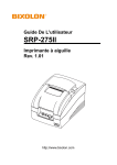
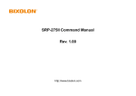
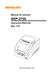
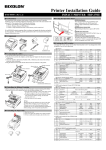
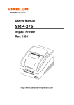
• Front view
Rear cover
• Rear view
Open button
DIP Switch cover
Power connect
Front cover
Drawer kick-out
connect
Control panel
Interface
connector
Power switch
NOTES
Please be sure to read the instructions in this manual carefully before using your new printer.
Rev. 1.00
-6-
SRP-275II
■ Table of Contents
1. Setting Up the Printer·······································································································8
1-1 Unpacking···················································································································8
1-2 Choosing a place for the printer··················································································8
1-3 Using the operation panel ···························································································9
2. Connecting the cables ···································································································10
2-1 Connecting the AC Adaptor·······················································································10
2-2 Connecting the Interface cable and Drawer kick-out cable ·······································10
2-2-1 Serial Interface (RS-232C)············································································11
2-2-2 Parallel Interface (IEEE1284)········································································12
2-2-3 USB Interface································································································13
2-2-4 Ethernet Interface ·························································································13
2-2-5 Drawer kick-out ·····························································································13
3. Setting the Switches ······································································································14
3-1 Setting the DIP Switch ······························································································14
3-1-1 DIP Switch setting for Citizen(iDP 3550) mode·············································15
3-1-2 DIP Switch setting for Star(SP500) mode ·····················································16
3-1-3 Changing the DIP Switch setting···································································17
3-2 Setting the Memory Switches ···················································································18
3-2-1 Memory Switch setting for Star mode ···························································22
4. Ribbon Cassette Installation ··························································································28
5. Roll Paper Installation ····································································································29
6. Installing the wall mount (Option)···················································································30
7. Self Test ·························································································································31
8. Hexadecimal Dumping···································································································32
9. Specification···················································································································33
9-1 Printing specification·································································································33
9-2 Paper specifications··································································································33
9-3 Ribbon cassette specification ···················································································33
9-4 Electrical characteristics ···························································································34
9-5 Reliability ··················································································································34
9-6 Environment conditions ····························································································34
9-7 Dimensions & weight ································································································35
9-8 Optional features ······································································································35
10. Appendix - Troubleshooting ·························································································36
10-1 ERROR LED blinking pattern··················································································36
10-2 The printer does not start printing ···········································································37
10-3 The printer stops printing ························································································38
10-4 You want to check the operation of the printer by itself···········································38
10-5 Printing is poor········································································································38
Rev. 1.00
-7-
SRP-275II
1. Setting Up the Printer
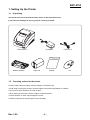
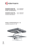
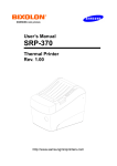
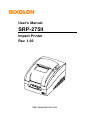
1-1 Unpacking
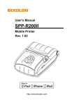
Your printer box should include the items shown in the illustration below.
If any items are damaged or missing, please contact your dealer.
SRP-275IIA, C
Ribbon cassette
AC adaptor
Paper roll
Manual
Power cord
CD
1-2 Choosing a place for the printer
• Avoid locations that are subject to direct sunlight or excessive heat.
• Avoid using or storing the printer in a place subject to excessive temperature or moisture.
• Do not use or store the printer in a dirty location.
• When setting up the printer, choose a stable, horizontal location.
• Intense vibration or shock may damage the printer.
• Ensure the printer has enough space to be used easily.
Rev. 1.00
-8-
SRP-275II
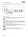
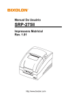
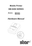
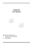
1-3 Using the operation panel
Most of the functions of this printer are governed by software, but you can monitor the printer s status by
looking at the lights on the control panel and for some procedures you will use the buttons.
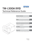
• Control panel
PAPER OUT
ERROR
POWER
FEED
- POWER LED (Green Color)
This indicator light is on when the power is turned on. It blinks when the printer is in the self
test printing standby state. Always wait until this indicator light stops blinking before you
start using the printer and before you turn it off.
POWER
- ERROR LED (Red Color)
ERROR
When this indicator light is on (but not blinking), it means that the printer is out of paper or
almost out of paper or the printer covers are open. When this light blinking, there is an
error. (See "ERROR LED blinking pattern" in Chapter 11.) If you see this light blinking, turn
off the printer for a few seconds and then turn it back on. If the light is still blinking, call your
supervisor or a service person.
- PAPER OUT LED (Red Color, not included with wall mount option)
When this indicator light is on, it means that the paper near end. Replace the new paper
roll. When ERROR and PAPER OUT indicator lights are on it means paper end. Install the
paper roll.(See "Installing paper roll" in Chapter 5.)
PAPER OUT
- FEED button
Use this button to feed paper or to start self test and for hexadecimal dump mode.
(See the instructions "Self test" (8) in this chapter for self test.)
(See the instructions "Hexadecimal dump" in Chapter 9 for hexadecimal dump mode.)
FEED
Rev. 1.00
-9-
SRP-275II
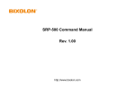
2. Connecting the cables
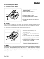
2-1 Connecting the AC Adaptor
• Connect the AC adapter according to the
AC adaptor
following procedure.
Power connector
1) Make sure the printer is turned off.
2) Before inserting the AC adaptor, connect the
power cord.
Power cord
3) Insert the AC adaptor as shown.
4) Plug the AC adapter cable into the printer’s
power connector.
5) Plug the power cord into the outlet, and turn on
the power.
CAUTION
Before connecting the printer to the power supply, make sure that the voltage and power specifications
match the printer’s requirements. Using an incorrect power supply can cause serious damage to the printer.
2-2 Connecting the Interface cable and Drawer kick-out cable
Interface
connector
• Connect the cables according to the
following procedure.
Drawer kick-out connector
1) Turn off printer and the host ECR (host
computer).
2) Plug the interface cable into the interface
connector on the printer then fasten the screw
on both sides of the connector.
Drawer kick-out
cable
3) Plug the drawer kick-out cable into the drawer
Serial/ Parallel/ USB/ Ethernet
Interface cable
kick-out connector on the printer.
(When removing the drawer kick-out cable,
press on the connector’s clip while pulling out.)
NOTES
Connect the printer to the host ECR (host computer) though an interface cable matching the specification of
the printer and the host ECR (host computer). Be sure to use a drawer that matches the printer’s
specification.
Depending on the interface your system uses, either connect the serial, parallel, USB or Ethernet
communication cable to the appropriate connector on the back of the printer. Cables are provided by your
dealer or system installer.
Rev. 1.00
- 10 -
SRP-275II
2-2-1
Serial Interface (RS-232C)
Interface connector
PRINTER
SIDE
(25Pin)
Pin No.
1
2
3
6
7
20
Signal name
FG
TxD
RxD
DSR
SG
DTR
Rev. 1.00
Drawer kick-out
Connector
(F.G) 1
1 (F.G)
(TXD) 2
2 (RXD)
(RXD) 3
3 (TXD)
(RTS) 4
4 (DTR)
(CTS) 5
5 (S.G)
(DSR) 6
6 (DSR)
(S.G) 7
7 (RTS)
(DTR) 20
8 (CTS)
Direction
Output
Input
Input
Output
Function
Frame Ground
Transmit Data
Receive Data
Data Set Ready
Signal Ground
Data Terminal Ready
- 11 -
HOST
SIDE
(9Pin)
SRP-275II
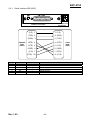
2-2-2 Parallel Interface (IEEE1284)
Drawer kick-out
Connector
Interface connector
Pin no.
Source
Compatibility mode
Nibble mode
Byte mode
1
Host
nStrobe
HostClk
HostClk
2
Host / Printer
Data 0 (LSB)
-
Data 0 (LSB)
3
Host / Printer
Data 1
-
Data 1
4
Host / Printer
Data 2
-
Data 2
5
Host / Printer
Data 3
-
Data 3
6
Host / Printer
Data 4
-
Data 4
7
Host / Printer
Data 5
-
Data 5
8
Host / Printer
Data 6
-
Data 6
9
Host / Printer
Data 7 (MSB)
-
Data 7 (MSB)
10
Printer
nAck
PtrClk
PtrClk
11
Printer
Busy
PtrBusy / Data3,7
PtrBusy
12
Printer
Perror
AckDataReq / Data2,6
AckDataReq
13
Printer
Select
Xflag / Data1,5
Xflag
14
Host
nAutoFd
HostBusy
HostBusy
15
-
NC
ND
ND
16
-
GND
GND
GND
17
-
GND
FG
FG
18
Printer
Logic-H
Logic-H
Logic-H
-
GND
GND
GND
31
Host
nInit
nInit
nInit
32
Printer
nFault
nDataAbail /
nDataAvail
33
-
NC
ND
ND
34
Printer
NC
ND
ND
35
Printer
NC
ND
ND
36
Host
nSelectln
1284-Active
1284-Active
19~30
Rev. 1.00
- 12 -
SRP-275II
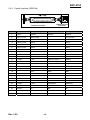
2-2-3 USB Interface
Drawer kick-out
Connector
Interface connector
Pin No.
Shell
1
2
3
4
2-2-4
Signal name
Assignment (Color)
Drain wire
Red
White
Green
Black
Shield
VBUS
DD+
GND
Ethernet Interface
Drawer kick-out
Connector
Interface connector
Pin No.
1
2
3
4
5
6
7
8
2-2-5
Function
Frame ground
NC
Differential data line
Differential data line
Signal ground
Signal name
TxD+
TxDRxD+
NC
NC
RxDNC
NC
Assignment (Color)
White with orange stripe
Solid orange
White with green stripe
Solid blue
White with blue stripe
Solid green
White with brown stripe
Solid brown
Function
Transmit +
Transmit Receive +
Receive -
Drawer kick-out
1
Pin No.
1
2
3
4
5
6
Rev. 1.00
6
Description
Signal GND
Drawer kick-out driver signal #1
Drawer Open / Close signal
+24V
Drawer kick-out driver signal #2
Signal GND
- 13 -
Direction
Output
Input
Output
-
SRP-275II
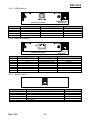
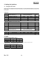
3. Setting the Switches
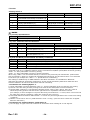
3-1 Setting the DIP Switch
Although the factory settings are best for almost all users, if you have special requirements, you can change
the DIP Switch. Your printer has two sets of DIP Switches. The functions of the switches are shown in the
following table.
• DIP Switch 1
Switch
1-1
1-2
1-3
1-4
1-5
1-6
1-7
1-8
Function
ON
Emulation Selection (*1)
OFF
Refer to the following table
Auto cutter
Compatible with SRP-275II
Serial interface selection
Print NV bit image #1 after cutting
Near end switch
Print column
Default
OFF
Enable
Enable
Memory Switch
Enable
Enable
42/35
Disable
Disable
DIP Switch
Disable
Disable
40/33
OFF
OFF
OFF
OFF
ON
OFF
ON
Ignore
Enable
XON/XOFF
7 bits
Enable
EVEN
OFF
Print “?”
Disable
DTR/DSR
8 bits
Disable
ODD
Default
OFF
OFF
OFF
OFF
OFF
OFF
OFF
OFF
• DIP Switch 2 (RS232C serial interface model)
Switch
2-1
2-2
2-3
2-4
2-5
2-6
2-7
2-8
Function
Data receive error
Black Mark Sensor
Hand shaking
Word length
Parity check
Parity selection
Baud rate selection (*2)
Refer to the following table
• DIP Switch 2 (Parallel interface model)
Switch
2-1
2-2~8
Function
Auto Line Feed
ON
Enable
Undefined
OFF
Disable
NOTES
(*1) Emulation Selection (DSW 1-1 and 1-2)
Emulation
BXL/POS
BXL/POS-KP
STAR
CITIZEN
1-1
OFF
ON
OFF
ON
1-2
OFF
ON
ON
OFF
- BXL/POS-KP(Kitchen Printer mode) : A alarm is generated by printer after auto cutting and in paper end error.
(*2) Baud rate selection (Transmission speed)
Transmission
2400 baud
4800 baud
9600 baud
19200 baud
Rev. 1.00
2-7
ON
OFF
OFF
ON
2-8
ON
ON
OFF
OFF
- 14 -
Default
OFF
OFF
SRP-275II
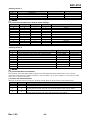
3-1-1
DIP Switch setting for Citizen(iDP 3550) mode
• DIP Switch 1
Switch
1-1
1-2
1-3
1-4
1-5
1-6
1-7
1-8
Function
ON
Emulation Selection (*1)
OFF
Refer to the following table
Auto cutter
Enable
CBM2 mode
(iDP3530 system)
CBM command
Disable
CBM1 mode
(iDP3540 system)
Default
OFF
OFF
OFF
International characters (*2)
Refer to the following table
ON
CR mode
CR
CR+LF
OFF
ON
8 bits
Disable
ODD
DTR/DSR
OFF
7 bits
Enable
EVEN
XON/XOFF
Default
ON
ON
ON
ON
• DIP Switch 2 (RS232C serial interface model)
Switch
2-1
2-2
2-3
2-4
2-5
2-6
2-7
2-8
Function
Word length
Parity check
Parity selection
Hand shaking
Baud rate selection (*3)
Refer to the following table
Near end switch
Mechanism type
Enable
Graphic
Disable
Character
NOTES
(*1) Emulation Selection (DSW 1-1 and 1-2)
Emulation
BXL/POS
BXL/POS-KP
STAR
CITIZEN
1-1
OFF
ON
OFF
ON
1-2
OFF
ON
ON
OFF
- BXL/POS-KP(Kitchen Printer mode) : A alarm is generated by printer after auto cutting and in paper end error.
(*2) International Character Selection
No.
Country
U.S.A.
France
Germany
U.K.
Denmark
Sweden
Italy
Windows Code
DSW 1-5
DSW 1-6
DSW 1-7
ON
OFF
ON
OFF
ON
OFF
ON
OFF
ON
ON
OFF
OFF
ON
ON
OFF
OFF
ON
ON
ON
ON
OFF
OFF
OFF
OFF
(*3) Baud rate selection (Transmission speed)
Transmission
2400 baud
4800 baud
9600 baud
19200 baud
Rev. 1.00
2-5
ON
OFF
OFF
ON
2-6
ON
ON
OFF
OFF
- 15 -
Code page
Page 0 (PC437 : U.S.A.)
Page 2 (PC850 : Multilingual)
Page 5 (PC865 : Nordic)
Page 2 (PC850 : Multilingual)
Windows Code
OFF
OFF
OFF
SRP-275II
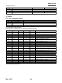
3-1-2
DIP Switch setting for Star(SP500) mode
• DIP Switch 1
Switch
1-1
1-2
1-3
1-4
1-5
1-6
1-7
1-8
Function
ON
Emulation Selection (*1)
OFF
Refer to the following table
Auto cutter
Black/Red Printing
Enable
Enable
Disable
Disable
Reserved
Default
OFF
OFF
OFF
OFF
• DIP Switch 2 (RS232C serial interface model)
Switch
2-1
2-2
2-3
2-4
2-5
2-6
2-7
2-8
Function
ON
OFF
Reserved
Hand shaking
Word length
Parity check
Parity selection
OFF
XON/XOFF
7 bits
Enable
EVEN
Baud rate selection (*2)
Default
DTR/DSR
8 bits
Disable
ODD
Refer to the following table
OFF
OFF
OFF
OFF
OFF
OFF
NOTES
(*1) Emulation Selection (DSW 1-1 and 1-2)
Emulation
BXL/POS
BXL/POS-KP
STAR
CITIZEN
1-1
OFF
ON
OFF
ON
1-2
OFF
ON
ON
OFF
- BXL/POS-KP(Kitchen Printer mode) : A alarm is generated by printer after auto cutting and in paper end error.
(*2) Baud rate selection (Transmission speed)
Transmission
2400 baud
4800 baud
9600 baud
19200 baud
2-7
ON
OFF
OFF
ON
2-8
ON
ON
OFF
OFF
NOTICE
Change in DIP Switch settings are recognized only when the printer power is turned on or when the
printer is reset by using the interface. If the DIP Switch setting is changed after the printer power is
turned on, the change does not take effect until the printer is turned on again or is reset.
Rev. 1.00
- 16 -
SRP-275II
3-1-3
Changing the DIP Switch setting
If you need to change settings, follow the steps below to make your changes.
CAUTION
Turn off the printer before removing the DIP Switch cover to prevent an electric short, which can damage
the printer.
1) Make sure the printer is turned off.
2) Remove the screw from the DIP Switch cover.
Then take off the DIP Switch cover, which is shown in the illustration below.
3) Set the switches using a pointed tool, such as tweezers or a small.
4) Replace the DIP Switch cover. Then secure it with the screw.
NOTES
The new settings take effect when you turn on the printer.
Rev. 1.00
- 17 -
SRP-275II
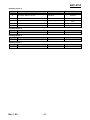
3-2 Setting the Memory Switches
This printer has “Memory Switch” set which is software switches. Memory Switch set has “MSW 2”, “MSW 8”,
“Customize value”, “Serial communication condition”. “Memory Switch setting utility” can change the Memory
Switch set to ON or OFF as shown in the table below (default: all OFF):
NOTES
The Memory Switch is available to be changed by three methods:
- Memory Switch setting utility
- Memory Switch setup mode (there are limitations on what can be changed)
- Control from command
- Some Memory Switch settings can be changed by the “Memory Switch setting mode”. See “Procedure of
Memory Switch setting”.
Settings of the Memory Switch are stored in the NV memory; therefore, even if the printer is turned off, the
settings are maintained. When you replace a SRP-270 with a SRP-275II, you should adjust the MSW 8-5 to
OFF.
• Memory Switch 2
Switch
1
2
3
4~8
Function
Reserved
Reserved
Reserved for Chinese selection
Code page selection (*1)
On
Off
Fixed to Off
Fixed to Off
Fixed to Off
Refer to the following table
NOTES
Desired code page can be selected using Memory Switch 2-4~8 by setting as following.
(*1) Code page selection
MSW 2-8
0
0
0
0
0
0
0
0
0
0
0
0
0
0
0
0
1
1
1
1
1
1
1
1
1
1
1
1
MSW 2-7
0
0
0
0
0
0
0
0
1
1
1
1
1
1
1
1
0
0
0
0
0
0
0
0
1
1
1
1
MSW 2-6
0
0
0
0
1
1
1
1
0
0
0
0
1
1
1
1
0
0
0
0
1
1
1
1
0
0
0
1
MSW 2-5
0
0
1
1
0
0
1
1
0
0
1
1
0
0
1
1
0
0
1
1
0
0
1
1
0
1
1
1
MSW 2-4
0
1
0
1
0
1
0
1
0
1
0
1
0
1
0
1
0
1
0
1
0
1
0
1
0
0
1
0
(*2) Only Font B available.
Rev. 1.00
- 18 -
Page
Page
Page
Page
Page
Page
Page
Page
Page
Page
Page
Page
Page
Page
Page
Page
Page
Page
Page
Page
Page
Page
Page
Page
Page
Page
Page
Page
Character Table
0 (PC437 : U.S.A.)
1 (Katakana)
2 (PC850 : Multilingual)
3 (PC860 : Portuguese)
4 (PC863 : Canadian-French)
5 (PC865 : Nordic)
16 (WPC1252 : Latin1)
17 (PC866 : Russian)
18 (PC852 : Latin2)
19 (PC858 : Euro)
21 (PC862 : Israel)
22 (PC864 : Arabic)
23 (Thai character code 42)
24 (WPC1253 : Greek)
25 (WPC1254 : Turkish)
26 (WPC1257 : Baltic)
27 (Farsi) (*2)
28 (WPC1251 : Russian) (*2)
29 (PC737 : Greek) (*2)
30 (PC775 : Baltic) (*2)
31 (Thai character code 14)
32 (OldCode : Israel)
33 (WPC1255 : Israel)
34 (Thai character code 11)
35 (Thai character code 18)
37 (PC857 : Turkish)
38 (PC928 : Greek)
41 (WPC1258 : Vietnam)
SRP-275II
• Memory Switch 8
Switch
1
2
3
4
5
6
7
8
Function
Upside down
Font Selection
Selection Paper End Buzzer
Reserved
Selection of the cover open status
Buffer Size
Receive buffer full release
On
Off
Off
Font A
On
Fixed to Off
Cover open
Paper end
40 bytes
8 Kbytes
Remaining 522 bytes
Remaining 640 bytes
Errors that can
Errors that
possibly recover
automatically recover
On
Font B
Off
Printer (Cover open during operation)
NOTES
MSW 8-5:
When Off is selected, a bit of the “paper end sensor” in each status that is transmitted from the printer is
changed every time the rear cover is open or closed. When On is selected, a bit of the “rear cover open /
close" in each status that is transmitted from the printer is changed every time the rear cover is open or
closed. When you replace a SRP-270 with a SRP-275II, you should adjust the MSW 8-5 to Off.
MSW 8-8:
When Off is selected, a bit of the “automatic recoverable error” in each status that is transmitted from
the printer is changed every time the rear cover is open. When On is selected, a bit of the “mechanical
error” in each status that is transmitted from the printer is changed every time the rear cover is open.
The setting of MSW 8-5 and 8-8 can be set by “Memory Switch setup mode”.
• Customize value
Function
Paper roll width
Selectable value
76 mm
NOTES
These setting can be set by “Memory Switch setup mode.”
• Serial communication
Function
baud rate
Parity
Handshake
Data length
Selectable value
2400 bps
4800 bps
9600 bps
19200 bps
None
Odd
Even
DSR/DTR
XON/XOFF
7 bit
8 bit
NOTES
There are two methods, DIP Switch and Memory Switch, to adjust the serial communication conditions.
DIP Switch 1-5 selects which is effective, DIP Switch or Memory Switch.
To enable the “Serial communication“ setting, you have to adjust the “Serial interface selection“ function
of DIP Switch 1-5 to “Memory Switch”.
These settings can be set by “Memory Switch setup mode”.
Rev. 1.00
- 19 -
SRP-275II
• Memory Switch Setup Mode
The following items are specified in the Memory Switch setup mode:
Basic Serial communication condition (Serial communication)
- Transmission speed
- Parity
- Handshaking
- Data length
Receive buffer full release condition (MSW 8-7)
Paper roll width (Customize value)
Cover open status (MSW 8-5)
NOTES
All new settings will be lost if the power supply is turned off in the Memory Switch setup mode. Be sure to
follow the proper procedure, and turn the power off at the correct time.
Use the following procedure to start the Memory Switch setup mode.
1) Open the rear cover.
2) Turn the power on while pressing the paper FEED button.
3) Press the FEED button twice while POWER, ERROR, and PAPER OUT LEDs are lit.
4) Close the cover. The printer prints the enabled settings of the Memory Switches and instructions.
5) Follow the instructions to process the switch setup.
NOTES
In the Memory Switch setup, the power LED may be flashing.
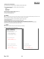
• Example of Memory Switch setup sheet
Memory S/W Setup
You can choose desired item using
YES or NO as following
YES: Keep pressing FEED button
Until printing starts
NO : Press & release it swiftly
Serial interface setting
Do you want to change
Serial interface condition?
Buffer full release condition
Cover open status
Current condition: 640 bytes left
Current status: Paper out
Do you want to change
Buffer full release condition?
Do you want to change
cover open status?
Rev. 1.00
- 20 -
SRP-275II
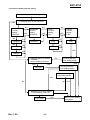
• Procedure of Memory Switch setting
Entering Memory Switch Setting Mode
NO
① Resetting Basic Serial Interface?
YES
Baud rate
Current
setting:
9600 bps
NO
19200bps
NO
NO
YES
NO
Handshake
Current
setting:
DSR/DTR
NO
Parity
Current
setting:
Non
YES
NO
YES
NO
YES
Even
YES
7 bits
NO
YES
4800bps
YES
Odd
NO
NO
2400bps
YES
NO
XON/XOFF
Data bit
Current
setting:
8 bits
YES
YES
NO
② Resetting Buffer full release
condition?
Current setting: 640 bytes
YES
NO
Finishing Memory
S/W Setting Mode?
YES
YES
Finishing Memory
S/W Setting Mode?
522 bytes
YES
Finishing Memory
S/W Setting Mode?
NO
NO
NO
③ Resetting Cover open status?
Current setting: Paper out
YES
NO
YES
Cover open
Rev. 1.00
- 21 -
YES
Memory S/W Setting
Completed
SRP-275II
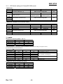
3-2-1
Memory Switch setting for Star mode
• Settings
Memory Switches are from MSW 0 to MSW 8. They are stored in non-volatile memory (flash memory). To
change the settings, send the following commands from the host.
[Name]
Set Memory Switch
[Code]
ASCII
ESC
GS
#
Hexadecimal
1B
1D
23
m {n1 n2 n3 0n4}0 ... {n1 n2 n3 n4}8 0A 00
Decimal
27
29
35
m {n1 n2 n3 0n4}0 ... {n1 n2 n3 n4}8 10 0
m {n1 n2 n3 0n4}0 ... {n1 n2 n3 n4}8 LF NUL
[Defined Region] m = "W", "T", ",", "+", "-", "@"
"0" ≤ n1,n2,n3,n4 ≤ "9",
"A" ≤ n1,n2,n3,n4 ≤ "F"
[Function]
Sends command to write after defining Memory Switch using the definition command
specified by the following classes to set the Memory Switch. The printer is automatically
reset after writing the setting defined by that command to the non-volatile memory.
Do not turn off the power to the printer while sending commands to the non volatile
memory. Doing so will destroy the Memory Switch setting. It is also possible for all Memory
Switch settings to become offset to their initial, default settings.
Consider the life of the non-volatile memory and avoid over-use of this command.
Function
Data Definition (Data Specification)
Data definition (set specified bit)
Data definition (clear specified bit)
Data Definition (clear all data)
Definition data write and reset
Definition data write and reset and test print
Class
Definition
Definition
Definition
Definition
Write
Write
m
","
"+"
"-"
"@"
"W"
"T"
{n1 n2 n3 0n4}0 ... {n1 n2 n3 n4}8
{n1 n2 n3 0n4}0 ... {n1 n2 n3 n4}8
{n1 n2 n3 0n4}0 ... {n1 n2 n3 n4}8
{n1 n2 n3 0n4}0 ... {n1 n2 n3 n4}8
Fixed at "0000"
Fixed at "0000"
Fixed at "0000"
(Ex) Memory Switch 1-8 = 0; Memory Switch 2-7 = 1: Memory Switch 2-A =1 for a test print:
PRINT #1, CHR$(&H1B);CHR$(&H1D);CHR$(&H23);CHR$(&H2D); ' <ESC><GS> # PRINT #1, CHR$(&H30);CHR$(&H30);CHR$(&H30);CHR$(&H30); ' 0000
PRINT #1, CHR$(&H30);CHR$(&H31);CHR$(&H30);CHR$(&H30); ' 0100
PRINT #1, CHR$(&H30);CHR$(&H30);CHR$(&H30);CHR$(&H30); ' 0000
PRINT #1, CHR$(&H30);CHR$(&H30);CHR$(&H30);CHR$(&H30); ' 0000
PRINT #1, CHR$(&H30);CHR$(&H30);CHR$(&H30);CHR$(&H30); ' 0000
PRINT #1, CHR$(&H30);CHR$(&H30);CHR$(&H30);CHR$(&H30); ' 0000
PRINT #1, CHR$(&H30);CHR$(&H30);CHR$(&H30);CHR$(&H30); ' 0000
PRINT #1, CHR$(&H30);CHR$(&H30);CHR$(&H30);CHR$(&H30); ' 0000
PRINT #1, CHR$(&H30);CHR$(&H30);CHR$(&H30);CHR$(&H30);CHR$(&H0A);CHR$(0); ' 0000 <LF><NUL>
PRINT #1, CHR$(&H1B);CHR$(&H1D);CHR$(&H23);CHR$(&H2B); ' <ESC><GS> # +
PRINT #1, CHR$(&H30);CHR$(&H30);CHR$(&H30);CHR$(&H30); ' 0000
PRINT #1, CHR$(&H30);CHR$(&H30);CHR$(&H30);CHR$(&H30); ' 0000
PRINT #1, CHR$(&H30);CHR$(&H34);CHR$(&H38);CHR$(&H30); ' 0480
PRINT #1, CHR$(&H30);CHR$(&H30);CHR$(&H30);CHR$(&H30); ' 0000
PRINT #1, CHR$(&H30);CHR$(&H30);CHR$(&H30);CHR$(&H30); ' 0000
PRINT #1, CHR$(&H30);CHR$(&H30);CHR$(&H30);CHR$(&H30); ' 0000
PRINT #1, CHR$(&H30);CHR$(&H30);CHR$(&H30);CHR$(&H30); ' 0000
PRINT #1, CHR$(&H30);CHR$(&H30);CHR$(&H30);CHR$(&H30); ' 0000
PRINT #1, CHR$(&H30);CHR$(&H30);CHR$(&H30);CHR$(&H30); CHR$(&H0A);CHR$(0); ' 0000<LF><NUL>
PRINT #1, CHR$(&H1B);CHR$(&H1D);CHR$(&H23);CHR$(&H54); ' <ESC><GS> # T
PRINT #1, CHR$(&H30);CHR$(&H30);CHR$(&H30);CHR$(&H30);CHR$(&H0A);CHR$(&H0); ' 0000 <LF><NUL>
Rev. 1.00
- 22 -
SRP-275II
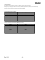
• Default Settings
The default settings for Memory Switch 0 to Memory Switch 8 are shown below.
Settings vary for single byte character countries (standard specifications (SBCS)) and for double-byte
character countries (Chinese character specifications (DBCS)).
- Standard Specifications (SBCS)
Memory Switch Number
MSW 0
MSW 1
MSW 2
MSW 3
MSW 4
MSW 5
MSW 6
MSW 7
MSW 8
Ex-factory Settings (n1, n2, n3, n4)
"0000"
"0000"
"0000"
"0000"
"0000"
"0000"
"0000"
"0000"
"0000"
- Chinese character specifications (DBCS) (For China)
Memory Switch Number
MSW 0
MSW 1
MSW 2
MSW 3
MSW 4
MSW 5
MSW 6
MSW 7
MSW 8
Rev. 1.00
Ex-factory Settings (n1, n2, n3, n4)
"0010"
"0000"
"0000"
"0000"
"0000"
"0000"
"0000"
"0000"
"0000"
- 23 -
SRP-275II
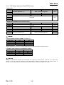
• Function
- Memory Switch 0
Bit
F~C
B~A
9~5
4
3~2
1~0
Function
Reserved
Red and Black
(inverted black and white) Commands (*3)
Reserved
0
1
Refer to the following table
SBCS
DBCS
(Single Byte countries) (Double Byte countries)
Refer to the following table
Country Specifications (*1)
<FF> Command (*2)
Reserved
NOTES
(*1) Country Specifications
Country
Overseas
MSW 0-4 = 0
Standard Specifications
MSW 0-4 = 1
Chinese Characters
(*2) <FF> Command Function Selection
MSW 0-3 MSW 0-2
Auto cutter model
0
0
0
1
1
0
1
1
<FF> Command Function
<FF> Command Function
Tear Bar Model (SRP-275IIA type)
Executes a form feed.
Executes a form feed.
After paper fed to cutting position
Paper fed to the tear-bar position
executes partial cut (*3)
Executes a form feed.
Executes a form feed.
After paper fed to cutting position
Paper fed to the tear-bar position
executes partial cut (*3)
(*3) Red and Black (inverted black and white) Commands
MSW 0-B
0
0
1
1
MSW 0-A
0
1
0
1
<ESC> 4 / <ESC> 5 Command Functions
White/black inverted printing (1 Pass)
<Option 1> White/black inversion (7 × 9 font print) + enhancing (2 passes)
<Option 2> Upper line + Underline + enhancing (2 passes)
<Option 3> Upper line + Underline + double tall expanded + enhancing (4 passes)
This setting functions to specify adornments when the subsequent red (white/black inversion) print
command is set. It is a substitute function for the conventional red/black (white/black inversion) printing.
<ESC> “4”: Red (white/black inversion) printing
<ESC> “5”: Red (white/black inversion) printing cancelled.
When using <ESC> 5 to cancel adornments, it returns to the previously set adornments. (Adornments
such as underline, upper line, double-tall expanded and enhancing are cancelled if there is no command
to set them (for example the <ESC> “-” 1 specification for underlines).)
This setting is enabled only for ANK characters and block characters. It is disabled for IBM block
characters and Chinese characters composed of 12 dot vertical characters (IBM block characters and
Chinese characters do not have adornment with this command).
- Precautions for selecting Option 1.
1) Prints white/black inverted characters using 7 × 9 fonts regardless of the current font size setting.
2) Inserts a one dot string of black printing to the head of the white/black inverted characters.
3) Printing data created on a conventional red/black printer, using 1 and 2 above, there are cases in
which the printing position will shift to the right and a line of printable characters reduced.
(For example, to write 42 digits of red print data using conventional a 7 × 9 font, there is a line feed at
the 35th digit, and the remaining 7 digits are printed on the next line.)
4) Download defined characters defined with 7 × 9 fonts are printed regardless of the current font setting
(7×9/9×9).
5) MSW 3-6 must not be set to 1 (ANK character count = many). (This will cause a while line to appear
between characters.)
- Precautions for selecting Option 2 and Option 3.
1) Do not apply an upper line or an underline to characters when rotating 90 or 270 degrees.
Rev. 1.00
- 24 -
SRP-275II
- Memory Switch 1
Bit
F
E~5
4
3~0
Function
Reserved
0
Zero style
International Characters (*1)
1
Normal
Slash zero
Refer to the following table
NOTES
(*1) International Characters Default Value Settings
MSW1-3
MSW1-2
MSW1-1
MSW1-0
0
0
0
0
0
0
0
1
0
0
1
0
0
0
1
1
0
1
0
0
0
1
0
1
0
1
1
0
0
1
1
1
1
0
0
0
1
0
0
1
1
0
1
0
1
0
1
1
International Characters
U.S.A
France
Germany
U.K.
Denmark1
Sweden
Italy
Spain1
Japan
Norway
Denmark2
PC-999
- Memory Switch 2
Bit
F
E
D~C
B
A
9~4
3
2
1~0
Function
Reserved
How to recover to print ready after inserting paper
Reserved
Contextual auto-cut function (*1)
0
1
Press FEED.
Auto-recovery
Disabled
Enabled
Refer to the following table
Near end switch function (*2)
NOTES
(*1) Contextual Auto-cut Function
This function auto-cuts paper when a paper feed command that feeds continuously over 7/6 inch.
Hosts that cannot send an escape sequence, such as <ESC> “d” 0 can cut paper if a 1/6 inch line feed
code <LF> is sent seven times.
(*2) Near end switch Function
When an near end switch is mounted, settings should abide by those shown in the table below.
MSW 2-1
0
0
MSW 2-0
0
1
1
0
1
1
Rev. 1.00
Near end switch Function
Disabled
Disabled
Reflects the near end switch state to the status.
Printing does not stop for near end, and the printer does not go offline.
Reflects the near end switch state to the status.
Printing does stop for near end, and the printer goes offline.
- 25 -
SRP-275II
- Memory Switch 3
Bit
F~D
C~8
7~2
1~0
Function
0
1
Character Table (*2)
Refer to the following table
<CR> Command Functions (*1)
Refer to the following table
NOTES
(*1) <CR> Command Functions
MSW3-1
0
0
1
1
MSW3-0 <CR>
0 Ignored
1 Ignored
0
1
Functions
Prints and performs a line feed (same as <LF>.)
Prints (No line feed)
(*2) Character Table Settings
These settings are enabled only on standard specification printers.
MSW3-C
0
0
0
0
0
0
0
0
0
0
0
0
0
0
0
0
1
1
1
0
1
1
1
1
1
1
1
1
MSW3-B
0
0
0
0
0
0
0
0
1
1
1
1
1
1
1
1
0
0
0
0
0
0
0
0
1
1
1
1
MSW3-A
0
0
0
0
1
1
1
1
0
0
0
0
1
1
1
1
0
0
0
0
1
1
1
1
0
1
1
1
MSW3-9
0
0
1
1
0
0
1
1
0
0
1
1
0
0
1
1
0
0
1
1
0
0
1
1
0
0
0
1
MSW3-8
0
1
0
1
0
1
0
1
0
1
0
1
0
1
0
1
0
1
0
1
0
1
0
1
0
0
1
0
(*3) Only Font B available.
Rev. 1.00
- 26 -
Page
Page
Page
Page
Page
Page
Page
Page
Page
Page
Page
Page
Page
Page
Page
Page
Page
Page
Page
Page
Page
Page
Page
Page
Page
Page
Page
Page
Character Table
0 (PC437 : U.S.A.)
1 (Katakana)
2 (PC850 : Multilingual)
3 (PC860 : Portuguese)
4 (PC863 : Canadian-French)
5 (PC865 : Nordic)
16 (WPC1252 : Latin1)
17 (PC866 : Russian)
18 (PC852 : Latin2)
19 (PC858 : Euro)
21 (PC862 : Israel)
22 (PC864 : Arabic)
23 (Thai character code 42)
24 (WPC1253 : Greek)
25 (WPC1254 : Turkish)
26 (WPC1257 : Baltic)
27 (Farsi) (*3)
28 (WPC1251 : Russian) (*3)
29 (PC737 : Greek) (*3)
30 (PC775 : Baltic) (*3)
31 (Thai character code 16)
32 (OldCode : Israel)
33 (WPC1255 : Israel)
34 (Thai character code 11)
35 (Thai character code 18)
37 (PC857 : Tukish)
38 (PC928 : Greek)
41 (WPC1258 : Vietnam)
SRP-275II
- Memory Switch 4
Bit
F~9
8
Function
0
Automatic Status Function
Disabled
ESC RS a n command function
Only Setting
Data reception error (serial)
Prints “?”
1
Enabled
7~4
3
2~1
0
Auto-status sent only
once
Ignored
- Memory Switch 5
Bit
F~0
Function
Reserved
0
1
Function
Reserved
0
1
Function
Reserved
0
1
- Memory Switch 6
Bit
F~0
- Memory Switch 7
Bit
F~0
Rev. 1.00
- 27 -
SRP-275II
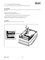
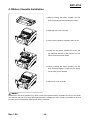
4. Ribbon Cassette Installation
1) Before inserting the ribbon cassette, turn the
knob clockwise to prevent twisting the ribbon.
2) Open the front cover of printer.
3) Take out the old ribbon cassette if there is one.
4) Insert the new ribbon cassette as shown and
pay particular attention to the placement of the
ribbon behind the Printer Head.
5) During inserting the ribbon cassette, turn the
knob clockwise again to make sure the ribbon
moves freely in the cassette.
6) Close front cover of printer.
NOTES
Malfunctions and other problems may arise if other than specified ribbon cassettes are used in the printer.
The Warranty may be void if other than specified ribbon cassettes are used. Contact your dealer or place of
purchase for more information about proper ribbon cassettes.
Rev. 1.00
- 28 -
SRP-275II
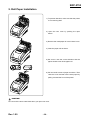
5. Roll Paper Installation
1) To prevent data loss, make sure that the printer
is not receiving data.
2) Open the rear cover by pushing the open
button.
3) Remove the used paper roll core if there is one.
4) Insert the paper roll as shown.
5) Be sure to note the correct direction that the
paper should come off the paper roll.
6) Pull out small amount of paper as shown. Then
close the cover and tear off the extra paper by
pulling it toward the front of the printer.
CAUTION
Do not touch the auto cutter blade when you open rear cover.
Rev. 1.00
- 29 -
SRP-275II
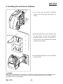
6. Installing the wall mount (Option)
Bracket hanger
1) Turn the Set over and attach the Bracket
hanger to the Frame base then tighten four
screws.
Screw(3x5)
(4pieces)
2) Attach the Bracket mount to the wall firmly with
Bracket mount
the eight screws. Be sure that the Bracket
attached properly to match the direction of
arrow as shown. And the Bracket mount should
be always fixed vertically.
Screw(4x10)
(8pieces)
3) Insert the Bracket hanger of Set to the Bracket
mount as shown.
NOTES
Wall mount is an optional item. DIP switch 1-7 should be set to OFF because wall mount installation does
not support Paper Out sensor. Contact seller or store you purchased the product from for detailed
information on wall mount installation.
Rev. 1.00
- 30 -
SRP-275II
7. Self Test
The self test let you know if your printer is operating properly. It checks the printing quality, ROM version,
DIP Switch settings, memory switch settings and statistic data.
The test is independent of any other equipment or software, so it is a good idea to run it when you first set
up the printer or if you have any trouble. If the self test works correctly, the problem is in the other equipment
or the software, not the printer.
• Running the self test
1) Make sure the printer is turned off and the printer cover is closed properly.
2) Turn on the power while pressing the Feed button and release the button, then the paper will feed. Self
diagnostics will begin and printer settings will be printed. Paper will be cut upon completion of the test and
printing will stop. (ERROR lamp will be on.)
3) Press the FEED button to continue printing the statistic data.
4) Press the FEED button to continue printing the rolling ASCII pattern.
5) The self test mode terminates after printing the rolling ASCII pattern automatically.
Rev. 1.00
- 31 -
SRP-275II
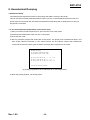
8. Hexadecimal Dumping
• Hexadecimal dump
This feature allows experienced users to see exactly what data is coming to the printer.
This can be useful in finding software problems. When you turn on the hexadecimal dump function, the
printer prints all commands and other data in hexadecimal format along with a guide section to help you
find specific commands.
• To use the hexadecimal dump feature, follow these steps:
1) After you make sure that the printer is off, open the rear cover of the printer.
2) Hold down the FEED button while you turn on the printer.
3) Close the rear cover.
4) Run any software program that sends data to the printer. The printer prints "Hexadecimal dump" and
then all the codes are received in a two column format. The first column contains the hexadecimal
codes and the second column gives the ASCII characters that correspond to the codes.
Hexadecimal Dump
To terminate hexadecimal dump
Press FEED button three times
1B 21 00 1B 26 02 40 40 . ! . . & . @ @
1B 25 01 1B 63 34 00 1B . % . . c 4 . .
41 42 43 44 45 46 47 48 A B C D E F G H
<Online Hex Dump Completed>
(A period(.) is printed for each code that has no ASCII equivalent.)
5) When the printing finishes, turn off the printer.
Rev. 1.00
- 32 -
SRP-275II
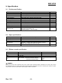
9. Specification
9-1 Printing specification
Item
Printing method
Head wire
Dot pitch
Dot wire diameter
Printing direction
Characters per line
Printing speed
Printing width
Line interval
Paper feed method
Paper feed speed
Character font
Description
Serial impact method
9 pin serial type
0.352mm (1/72”)
0.28mm (0.01”)
Bidirectional (logic seeking) with friction feed
Max. 42 (characters)
5.1 LPS (Line Per Second)
63.5 mm
4.233 mm (1/6”)
Friction feed
Approximately 158 mm (6.2”)
7x9/9x9
Alphanumeric characters : 95
International characters : 48
Extended graphics : 128 x 27 pages
Character sets
Remark
9-2 Paper specifications
Item
Paper type
Paper roll width
Paper roll diameter
Normal paper
Paper core outside diameter
Description
Paper roll
76±0.5 mm
Max. ø83 mm (3.27")
Thickness : 1 sheet 0.06~0.085 mm (0.0024~0.0034")
Weight : 52.3~64g/m2 (0.115~0.1411 lb)
Max. ø19mm (0.75")
Remark
9-3 Ribbon cassette specification
Item
Description
Standard
Color
Size
RRC-201BR
Black & Red
13 mm (W)
Life
RRC-201BR : 1,500,000 characters (Black)
750,000 characters (Red)
Remark
Continuous printing 7x9 font
ASCII
25℃
NOTES
Malfunctions and other problems may arise if other than specified ribbon cassettes are used in the printer.
The Warranty may be void if other than specified ribbon cassettes are used. Contact your dealer or place
of purchase for more information about proper ribbon cassettes.
Rev. 1.00
- 33 -
SRP-275II
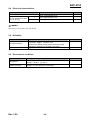
9-4 Electrical characteristics
Item
SMPS Supply voltage
Current consumption
(at 24V, except for drawer
kick-out driving)
Operating
Standby
Description
24VDC
Mean : Approximately 0.5A
Peak : Approximately 1.5A
Remark
Mean: Approximately 0.3A
NOTES
Maximum 1A for drawer kick-out driving.
9-5 Reliability
Item
Life firing frequency
Head
Description
Mechanism : Approx. 18 million lines
Auto cutter : Approx. 1.5 million cuts
(End of life is defined as the point at which the printer
reaches the beginning of the Wear out Period.)
Approx. 300 million dots/wire
Remark
9-6 Environment conditions
Item
Temperature
Relative humidity
Rev. 1.00
Description
Operating : 0~45℃ (32~113℉)
Storage : -20~60℃ (-4~140℉)
Operating : 10~80% RH (Non-condensing)
Storage : 10~90% RH (Non-condensing)
- 34 -
Remark
SRP-275II
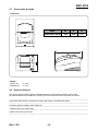
9-7 Dimensions & weight
• Dimensions
• Weight
Approx. Wt.
Shipping Wt.
Item
W
D
H
Dimension (mm)
160
239
157
: 2.5 kg
: 4.0 kg
9-8 Optional features
The optional features either replace a standard feature or enhance the operation of the printer.
All optional features are installed at the factory and must be selected when the printer is ordered.
-----------------------------------------------------------------------------------------------------------------------------------------------• Auto cutter (SRP-275IIA : Exclude auto cutter, SRP-275IIC : Including auto cutter)
-----------------------------------------------------------------------------------------------------------------------------------------------• Interface (Serial / Parallel / USB / Ethernet)
-----------------------------------------------------------------------------------------------------------------------------------------------• Cabinet color (Ivory / Dark gray)
-----------------------------------------------------------------------------------------------------------------------------------------------• Black mark sensor (front /rear)
------------------------------------------------------------------------------------------------------------------------------------------------
Rev. 1.00
- 35 -
SRP-275II
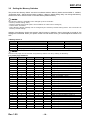
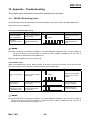
10. Appendix - Troubleshooting
This chapter gives solutions to some printer problems you may have.
10-1 ERROR LED blinking pattern
The printer stops all printer operations for the selected paper section, goes off line, and the ERROR LED
blinks when an error is detected.
• Errors that automatically recover
Error
Description
Rear cover open error
(When recoverable
Error is selected)(*1)
The rear cover is opened
when printing
Print head
temperature error(*2)
The temperature of the
print head is extremely
high.
ERROR LED blinking pattern
200ms
Recovery
Recovers automatically
when the rear cover is
closed.
Recovers automatically
when the print head
cools.
NOTES
(*1) These conditions are selected by MSW8-5, 8-8. When MSW8-5 (mapping of the cover open status) is
off, the error hasn’t occurred but there is a “paper end error” instead. If MSW8-8 is off, this error is
handled as an automatically recoverable error.
(*2) Print head temperature error is not abnormal.
• Recoverable errors
When a recoverable error occurs, after the cause of the error is removed, the printer can recover from the
error by receiving an error recovery command without turning off the power.
Error
Description
ERROR LED blinking pattern
Rear cover open error
(*1)
The rear cover is opened
when printing.
Auto cutter error
(Type C only)
The auto cutter does not
work correctly.
Recovers by error
recovery command.
Home position
detection error (This
is “Mechanical error”)
The home position
cannot be detected due
to a paper jam.
Recovers by error
recovery command.
200ms
Recovery
Recovers automatically
when the rear cover is
closed.
NOTES
(*1) These conditions are selected by MSW8-5, 8-8. When MSW8-5 (mapping of the cover open status) is
off, the error hasn’t occurred but there is a “paper end error” instead. If MSW8-8 is off, this error is
handled as an automatically recoverable error.
Rev. 1.00
- 36 -
SRP-275II
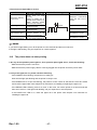
• Errors that are impossible to recover
Error
R/W error in memory
or gate array
High voltage error
Low voltage error
CPU execution error
Print head temperature
detection circuit error.
Description
ERROR LED blinking pattern
After R/W checking, the
printer does not work
correctly.
Writing to, reading out, or
erasing the NV memory for
image scanning results
does not work correctly.
The power supply voltage
is extremely high.
The power supply voltage
is extremely low.
The CPU executes an
incorrect address or I/F
board is not connected.
There is an abnormality is
the print head temperature.
Recovery
Recovers automatically
when the rear cover is
closed.
200ms
Impossible to recover.
Impossible to recover.
Impossible to recover.
Impossible to recover.
NOTES
If you see this light blinking, turn off the printer for a few seconds and then turn it back on.
If the light is still blinking, call your supervisor or a service person.
10-2 The printer does not start printing
• Are any of the operation panel lights on, If no operation panel lights are on, check the following:
- Make sure that the printer is turned on.
- Make sure that the power supply cable is correctly plugged into the printer and to the power outlet.
• If any of the lights are on, please check the following:
- If the POWER LED is blinking, the printer is not ready yet.
Wait until the light quits blinking and the printer is ready to use.
- If the ERROR LED is on (but not blinking), the printer is off line. Check to see that the covers are closed
and check the paper state. See Chapter 5 for instructions on installing or replacing the paper roll.
- If the ERROR LED is blinking, there is an error. In this case, turn off the printer for a few seconds and
then turn it back on. If the light is still blinking, call your supervisor or service person.
- If the PAPER OUT LED is on, check the paper roll in the printer. See Chapter 5 for instruction on
installing the paper roll.
Rev. 1.00
- 37 -
SRP-275II
10-3 The printer stops printing
• If the ERROR LED is on (but not blinking), the printer is off line. Check to see that the covers are closed
and check the paper state. See Chapter 5 for instructions on installing or replacing the paper roll.
• If the ERROR LED is blinking, there is an error. In this case, turn off the printer for a few seconds and then
turn it back on. If the LED is still blinking, call your supervisor or a service person.
• Turn off the printer and check for a paper jam. To clear paper jam, follow the steps below:
1) Turn off the printer and open the rear cover of the printer.
2) Remove the jammed paper and reload the paper roll as described in Chapter 5.
3) Close the rear cover.
4) Turn on the printer.
10-4 You want to check the operation of the printer by itself
• Self test
Try to run the self test to check that the printer works properly. See the self test instructions in Chapter 8
to run the self test. If the self test does not work, contact your supervisor or a service person.
If the self test works properly, check the following:
1) Check the connection at both ends of the interface cable between the printer and the computer. Also
make sure that this cable meets the specifications for both the printer and the computer.
2) The data transmission settings may be different between the printer and computer. Make sure that the
printer’s DIP Switch settings for data transmission are the same as the computer’s. You can see the
printer’s interface settings on your self test printout.
NOTES
If the printer still does not print, contact your dealer or a qualified service person.
10-5 Printing is poor
Check the state of ribbon cassette. If the ribbon cassette life ends, replace the ribbon cassette as
described in Chapter 4.
NOTES
If the printer is still poor, contact your dealer or a qualified service person.
Rev. 1.00
- 38 -