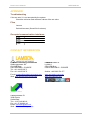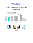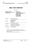
1
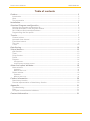
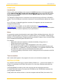
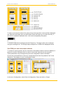
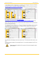
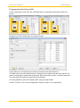
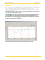
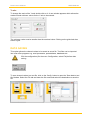
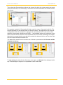
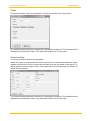
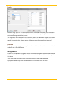
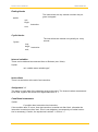
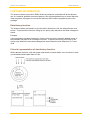
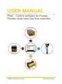
USER MANUAL
PNet – Control software for Pumps,
Powder doser and Gas flow controller
LAMBDA Laboratory Instruments
PNet Control Software
PNet Control Software
USER MANUAL
Table of contents
Preface....................................................................................................................... 2
Introduction ........................................................................................................................ 2
Hints .................................................................................................................................. 2
Text convention ................................................................................................................. 2
Installation................................................................................................................. 2
Standard Program configuration ............................................................................ 3
Opening the program configuration file .............................................................................. 3
General description of the program window ....................................................................... 3
Set COM port and instrument address ............................................................................... 4
Programming the flow profile ............................................................................................. 6
Trends........................................................................................................................ 7
Channel choice .................................................................................................................. 8
Automatic time interval....................................................................................................... 8
Fixed time interval .............................................................................................................. 9
The ruler ............................................................................................................................ 9
Y axis ................................................................................................................................10
Data Saving ............................................................................................................. 10
Virtual devices ........................................................................................................ 12
df/dt function .....................................................................................................................12
Timer ................................................................................................................................13
Pulse function ...................................................................................................................13
Profile ...............................................................................................................................14
Program ............................................................................................................................14
Configuration: ................................................................................................................................ 14
Programming language syntax: ..................................................................................................... 15
Alarm and report windows ..................................................................................... 18
Alarm window ...................................................................................................................18
Operation: ...................................................................................................................................... 18
Buttons and Icons: ......................................................................................................................... 18
Report window ..................................................................................................................19
Operation: ...................................................................................................................................... 19
Buttons and Icons: ......................................................................................................................... 19
Further information ................................................................................................ 20
Data history function .........................................................................................................20
Pictorial representation of data history function .................................................................20
Appendix ................................................................................................................. 21
Troubleshooting ................................................................................................................21
Files ..................................................................................................................................21
Occupied communication interfaces .................................................................................21
Contact Information................................................................................................ 21
www.lambda-instruments.com
1
PNet Control Software
USER MANUAL
PREFACE
Introduction
PNet is a PC control software for the control of LAMBDA laboratory instruments (peristaltic
pumps PRECIFLOW, MULTIFLOW, HIFLOW, MAXIFLOW, syringe pump VIT-FIT, powder
dosing instrument DOSER and gas flow controller MASSFLOW) and allows the programming of set point profiles.
The laboratory instruments are connected to the computer through a RS-232 or RS-485 interface. Then, the COM port to which the instrument is connected and its address are selected.
Up to 12 Pumps, 16 Massflow gas flow controllers, 36 Integrators can be connected and
managed simultaneously.
If other functions are needed, you can make contact with us ([email protected]). If possible, we will integrate the desired functions in your software system,
in such a way that it conforms optimally to your specifications.
Hints
An automation system should make the work easier. Before initiating the process, think of a
question: what will happen in the event of a system failure (e.g. an interface, measuring apparatus or PC breaking down)? Experimental set up should be made to have a minimal effect
due to breakdown and the system should be safe.
For example:
-
-
Appropriate valves are opened or closed automatically during power cut.
Pumps should not be overloaded.
Before leaving the program, switch all apparatus to the “Zero” position.
Your equipment must be capable of withstanding the most extreme possible conditions placed on it. (Example: For pressure regulation, your apparatus should be able
to tolerate the maximum pressure allowed by the safety valve).
To avoid overheating of electronic circuits, nothing should ever be placed on the D/A
converter box.
Text convention
Italic: words which appear in the program, like menu, text on buttons (example: OK)
INSTALLATION
Any extension cards that may be required (RS232, RS485, etc…) can then be installed. To
do this, it is necessary to exit PNet (Lea version 5.6), shut down Windows and switch the
computer off.
If a RS232/RS485 converter is to be used, this can also be connected at this time.
To install PNet (LEA version 5.6) insert the CD-ROM into the CD-ROM drive and start the
set-up program 'Setup.exe'.
Finally switch the various devices on, boot the computer and start PNet (Lea version 5.6).
www.lambda-instruments.com
2
PNet Control Software
USER MANUAL
STANDARD PROGRAM CONFIGURATION
The software is provided with an example configuration file based on your requirement. You
could use it or build your own application.
Please refer the user manual of SIAM (http://lambda-instruments.com/pdf/SIAM_IndustrialFermentation-Software-User-Manual.pdf) to know more about the procedure to generate a
visual configuration of your own which can be saved and reopened later.
A short video of the program configuration can be found at:
http://www.youtube.com/watch?v=K__aVvQQqQw
Opening the program configuration file
To open the present configuration file example, select the Open command in the File menu
and choose Open to open the configuration file PeristalticPump2xConfiguration.cfg.
An example configuration for 2 pumps will appear.
General description of the program window
While opening the program configuration file, a window opens with a possibility to
-
Send a set point to the pump
Configure, start or stop a flow profile
Save the data
Visualize and compare the data as trends
www.lambda-instruments.com
3
PNet Control Software
USER MANUAL
To enter a new set point value of the pump click on the input field. A second field is displayed
into which the new target value can be entered. Press the Enter key to confirm the entry. If
the value is outside the calibration limit, it will not be accepted by the system.
To close the field without change press the Escape key. The target value can be changed
using the scrolling arrow. The change steps correspond to 1/1000 of the displayed interval.
Set COM port and instrument address
To initiate the communication with the instrument, the software needs to know the address of
the device and the COM port which is used to connect the instrument to the computer.
These parameters can be changed only when the configuration mode is activated.
Choose the command Enter in the menu Configuration and enter the password “lea” in the
dialog box. The program is now in configuration mode.
In the menu Configuration, select Device Configuration, Pump and click on Pump1.
www.lambda-instruments.com
4
PNet Control Software
USER MANUAL
A new dialog box titled ‘Configuration for a Lambda pump’ will appear. Select the COM Port
to which the device is connected. Please refer the video
http://www.youtube.com/watch?v=fCQX7vRp9aY for setting up and checking the COM port
number on PC.
Set address of the pump (refer to http://www.lambdainstruments.com/?pages=peristaltic_pump_preciflow_remote_control#pc-control for the
pump address).
Click on the Connected check box to initiate communication between the PC and the device.
Close the dialog box with OK.
The message ‘Unknown COM error’ or ‘Timeout’ will appear if the software cannot communicate with the pump. In this case check the COM port and the address on the pump and
whether the cable is well connected.
The Description field displays the internal device name. The Information field is free for user
input.
Repeat the same procedure for connecting Pump 2, 3, etc and the Integrator to the PC control software.
Please note that the address of the pump and its internal integrator (optional) is the same.
www.lambda-instruments.com
5
PNet Control Software
USER MANUAL
Programming the flow profile
In the Configuration menu click the command Device configuration and select Profile1 for
pump 1.
Dialogue box titled Configuration for profile will open.
Flow profiles up to 50 steps can be entered, saved as a file and printed out.
The start value, end value and the time to change from the start to the end value can be created. It is important to respect the time format. When the profile is done, it can be saved (button Save) and the window is closed with the OK button.
It is also possible to open the created profile using the Open button.
Profile 2, Profile 3, etc. can be configured for Pump 2, pump 3, etc. respectively.
www.lambda-instruments.com
6
PNet Control Software
USER MANUAL
TRENDS
Up to 10 channels can be displayed as curves. They show the set point values of the different connected pumps and the actual value of integrators as a function of time.
In the curve, the legend displays the channel name, the unit and the last value. Time relates
to the last point entered.
To change the scale, double click on the axis. A second field is displayed into which the minimum and maximum values can be entered.
The
and
buttons reduce and enlarge the time interval and this
button displays a
ruler. The channel values are displayed in the legend and the corresponding time is displayed above right. This button inactivates the automatic curve renewal mode. It is possible
to return to this mode using the
button.
Curves showing the set points of the controlled pumps as a function of time.
www.lambda-instruments.com
7
PNet Control Software
USER MANUAL
Channel choice
To select a channel click on the
button. This opens a window in which the channel to be
displayed can be selected together with one of four axes and the curve colour.
Select a channel from the list, copy it into a field in the channel column with the ’>’ button.
Choose an axis (Y1 and Y2 are displayed on the left, Y3 and Y4 are displayed on the right).
Select a colour from the colour list. To delete a channel click on the ‘<’ button.
Automatic time interval
In this mode the new values are automatically added to the curves. The button
is down.
The time on the top right is the time of the last added data point. The speed of the curve displacement depends on the time interval.
To change this time interval, double click on the time axis; a new window appears. It contains
a time and a date, which correspond to the time at the left of the trend.
www.lambda-instruments.com
8
PNet Control Software
USER MANUAL
It is important to take care while formatting the fields. The date (DD/MM/YY format) and time
(HH:MM:SS) must have 2 characters (e.g. 01:58:09 08/01/14 = correct; 1:58:9 8/1/24 =
wrong). Clicking on the grid check box displays a grid.
It is also possible to change the time scale with the buttons
and
.
The time interval is limited to 3 days in this mode.
Fixed time interval
In this mode the curves are fixed. It is then possible to choose the time at the left and the
right of the trend. The rules for formatting the values are the same as for automatic time interval.
It is also possible to change the time scale with the buttons
and
.
The time interval can be up to 60 days.
The ruler
Click on the
button. If the trend was in automatic time interval mode it will change to fixed
time interval mode so that the curves become fixed.
A black cursor appears at the left of the trend. Clicking with the mouse displaces the cursor.
The legend shows the value of the channels and the corresponding time at the right.
When finished with this cursor, it can be deleted by clicking again on the
into automatic time interval mode by clicking on the
www.lambda-instruments.com
button or pass
button.
9
PNet Control Software
USER MANUAL
Y axis
To change the scale of the Y axis double click on it. A new window appears which allows the
maximum and minimum values for the Y axis to be entered.
The minimum value must be smaller than the maximal value. Clicking on the grid check box
shows a grid.
DATA SAVING
This option allows the channel values to be saved as a text file. Text files can be imported
into most office programs e.g. word processors, spreadsheets, databases etc.
Exit the configuration (On the menu Configuration, select Exit) before data
saving.
To save channel values to a text file, click on the Config. button to open the 'Save data to text
file' window. Select the File tab and enter the file name and select the destination to save the
file.
www.lambda-instruments.com
10
PNet Control Software
USER MANUAL
Then select the Channel tab and choose the channel for which the values need to be saved.
Select the Time tab, if it is necessary to record the time interval between two entries and the
time format.
For example: a period of 10 seconds will write a new line, every 10 seconds in the file. The
decimal separator for the saved values can also be chosen. This depends on the computer
configuration which will read the file. If the point is choosed and the PC uses comma as a
separator, the program (like Microsoft EXCEL,...) will probably interpret the values as a character chain and not as numbers. So the separator has to be chosen according to the needs.
Absolute time means that the recorded time contains the date and the time of the data. Relative time means that the time starts at 0.
The data will be saved from the moment the On button is pressed and the file name will be
displayed at the top.
To stop saving the data click the On button once again, and [None] will be displayed at the
top. If data storage is stopped, it is impossible to save further data.
www.lambda-instruments.com
11
PNet Control Software
USER MANUAL
VIRTUAL DEVICES
These devices are not connected to the computer, they are functions that manage one or
more channels.
df/dt function
Enter the calculation interval in seconds. The larger it is, the less background noise there will
be. Then enter the Factor (dependent on whether the unit is in: h-1, min-1, s-1) and select the
channel to be linked from the list.
The channel buttons allow each channel to be individually configured. The Description field
displays the internal device name. The Information field is free for user input.
www.lambda-instruments.com
12
PNet Control Software
USER MANUAL
Timer
This function allows a time to be displayed. This device functions like a stop watch.
The channel buttons allow each channel to be individually configured. The Description field
displays the internal device name. The Information field is free for user input.
Pulse function
This function allows a pulse to be generated.
Select the output to be accessed from the list and enter the minimum and maximum values
together with the times (hours, minutes and seconds) from the two states of the output. For
digital outputs enter the values 0 and 1. The output values for start and stop can also be selected with this function.
The channel buttons allow each channel to be individually configured. The Description field
displays the internal device name. The Information field is free for user input.
www.lambda-instruments.com
13
PNet Control Software
USER MANUAL
Profile
Enter the 'begin' and 'end' values and the duration. The format for duration must be correct:
use three figures for hours and two for minutes and seconds respectively. If the duration is
set to zero the segment will be ignored.
The 'begin' and 'end' values must be in the same interval, as defined for output. Then select
the output to be accessed from the list. It is possible to configure a ramp without linking to a
channel (none in the list). A ramp can be configured using the programming language.
Program
The programming language is a very advanced tool, which can be used to create control algorithms and on-line simulations.
Configuration:
A value can be calculated using this channel. Enter the unit together with the maximum and
minimum value of the result. All values which are outside this range will be rounded up to the
limit value.
These fields must be filled out even when the there is no result to be calculated.
A program can have up to 900 characters, which corresponds to 40 - 50 lines.
www.lambda-instruments.com
14
PNet Control Software
USER MANUAL
When all the values have been entered click on OK to confirm and save the configuration.
Programming language syntax:
The syntax analyser does not differentiate between lower case and capital letters e.g. pH1,
ph1, and PH1 when represented in the same channel.
Reserved words
-
activate, begin, boolean, else, end, getcontroller Y, getval, hi, hihi, if, init, lo, lolo, loop,
program , quit, real, reset, setval, start, stop, then, var.
These words may not be used as channel or variable names.
Program structure
The program is divided into three parts which must not necessarily be present at the same
time.
Initialising blocks
The instructions are only carried out when the program is started.
Syntax
init
begin
Instruction
end;
www.lambda-instruments.com
15
PNet Control Software
USER MANUAL
Ending blocks
The instructions are only carried out when the program is stopped.
Syntax
quit
begin
Instruction
end;
Cyclic blocks
The instructions are carried out cyclically ca. every
second.
Syntax
loop
begin
Instruction
end;
Internal variables
These can be declared as command lines or Boolean (true / false).
Syntax
var’ variable name variable type’;’
Instructions
There is a semicolon at the end of an instruction.
Assignment ‘:=’
The terms on each side of the character must be the same. The channel values are assumed
to be Real, together with those from digital channels 0 or 1.
Conditional statements
Syntax
if condition then instruction else instruction;
If the condition after 'if' is true, then the instruction is carried out after 'then', otherwise the
instruction is carried out after 'else'. 'Else' is not obligatory (consequently no further instruction is necessary). Caution, the equals test is written ‘=’ and not ‘:=’.
www.lambda-instruments.com
16
PNet Control Software
USER MANUAL
Operators
+, -, *, /
AND, OR, NOT
=, >, <, >=, <=
The values allowed range from -10000 to -0.00001 and from 0.00001 to 10000. The value 0
is also allowed except for a division. If a calculation results in a value outside this range the
program is automatically stopped.
Procedures
Channels can be accessed in order to change a target value, start a ramp etc. Lower or upper case characters may be used.
SetVal (channel name, comma value)
The channel must be a digital or analog output or a program channel.
Functions
Functions deliver values which are mainly comma values that can be assigned to a variable
or a channel.
GetVal(channel name)
This command allows access to values from digital or analog inputs and outputs, sample
management channels, weight measurements etc.
The values supplied are real.
Error management
After pressing the OK button the program syntax is checked; if an error is found an error
message is displayed.
www.lambda-instruments.com
17
PNet Control Software
USER MANUAL
ALARM AND REPORT WINDOWS
The alarm and report windows are always available, they cannot be closed.
Alarm window
Operation:
When an alarm is triggered the date, time, channel name and value are automatically entered into the alarm list. To cancel an acoustic alarm, press the Acknowledge button.
After an alarm has been acknowledged it can be deleted from the list selecting the alarm
from the list and pressing the Delete button. It is recommended that the list of alarm messages is deleted from time to time as they take up storage capacity.
Buttons and Icons:
Print out the contents of the window
Acoustic alarm
Optical alarm
www.lambda-instruments.com
18
PNet Control Software
USER MANUAL
Report window
Operation:
This window functions like a simple text editor. Individual remarks can be written here.
Additionally most user interventions are automatically entered and it is also possible for the
user to enter these messages:
-
Controller and function start and stop
Alarms
Buttons and Icons:
opens a text file (*.txt)
Save text to a file
Print out the contents of the window
www.lambda-instruments.com
19
PNet Control Software
USER MANUAL
FURTHER INFORMATION
The channel values are saved in RAM. When the computer is switched off all the data are
lost. It is however possible to save the data to a file and manipulate them at a later date with
other programs. A program to convert the data into ASCII code is supplied as part of the
package.
Data history function
The channel values are stored in a circular buffer. When this is full the oldest data are over
written. To prevent the buffer from filling up too quickly only data which has been changed is
saved.
Example:
If the temperature remains constant for 2 hours only one point is saved In addition some of
the channels may have a lot of background noise. To prevent the buffer from filling up too
quickly only data which have been changed are saved when the time difference is > 8 seconds.
Pictorial representation of data history function
When data are saved to a file the system searches the circular buffer once a minute for newly entered data and copies them to a file.
www.lambda-instruments.com
20
PNet Control Software
USER MANUAL
APPENDIX
Troubleshooting
If the set value Y is not accepted by the system:
Check the minimum and maximum values of the set value
Files
Lea.exe
Quickchimes.wav (Sound file for alarms)
Occupied communication interfaces
COM1
COM2
COM3
COM4
CONTACT INFORMATION
LAMBDA Laboratory Instruments
Sihlbruggstrasse 105
CH-6340 Baar
SWITZERLAND – EUROPE
Tel.: +41 444 50 20 71
Fax: +41 444 50 20 72
LAMBDA CZ s.r.o.
Lozíbky 1
CZ-61400 Brno
CZECH REPUBLIC – EUROPE
E-mail: [email protected]
Web: www.lambda-instruments.com
www.peristaltic-pumps.eu
www.syringepump.info
Hotline: +420 603 274 677
SYSMATEC
Oberdorfstrasse 51
3930 Eyholz
Switzerland
Tel + 41-27-946-80-18
Fax + 41-27-946 86-42
Email: [email protected]
Web : www.rhone.ch/sysmatec
www.lambda-instruments.com
21