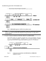
1
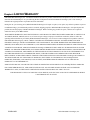
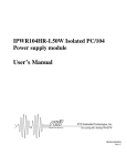
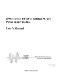
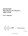
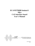
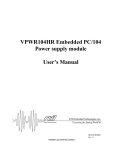
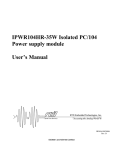
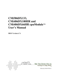
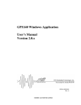
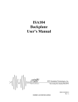
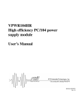
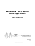
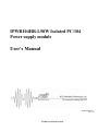
IPWR104HR-L50W Isolated PC/104
Power supply module
User’s Manual
BDM-610020055
Rev. A
ISO9001 and AS9100 Certified
IPWR104HR-L50W
Power supply module
User’s Manual
RTD Embedded Technologies, INC.
103 Innovation Blvd.
State College, PA 16803-0906
Phone: +1-814-234-8087
FAX: +1-814-234-5218
E-mail
[email protected]
[email protected]
web site
http://www.rtd.com
IPWR104HR
2
RTD Embedded Technologies, Inc
Revision History
Rev. A
Initial release
Published by:
RTD Embedded Technologies, Inc.
103 Innovation Blvd.
State College, PA 16803-0906
Copyright 1999, 2002, 2003 by RTD Embedded Technologies, Inc.
All rights reserved
Printed in U.S.A.
The RTD Logo is a registered trademark of RTD Embedded Technologies. cpuModule and utilityModule are trademarks of RTD
Embedded Technologies. PhoenixPICO and PheonixPICO BIOS are trademarks of Phoenix Technologies Ltd. PS/2, PC/XT, PC/AT and
IBM are trademarks of International Business Machines Inc. MS-DOS, Windows, Windows 95, Windows 98 and Windows NT are
trademarks of Microsoft Corp. PC/104 is a registered trademark of PC/104 Consortium. All other trademarks appearing in this document
are the property of their respective owners.
IPWR104HR
3
RTD Embedded Technologies, Inc
IPWR104HR
4
RTD Embedded Technologies, Inc
TABLE OF CONTENTS
CHAPTER 1
INTRODUCTION ..................................................................................... 8
Features........................................................................................................................................................................ 8
Some of the key features of the IPWR104HR include: ........................................................................................ 8
Power supply units...................................................................................................................................................... 8
Mechanical description............................................................................................................................................... 9
Connector description ................................................................................................................................................ 9
What comes with your board..................................................................................................................................... 9
Using this manual........................................................................................................................................................ 9
When you need help.................................................................................................................................................... 9
CHAPTER 2
BOARD INSTALLATION ...................................................................... 10
Board installation...................................................................................................................................................... 10
General installation guidelines:........................................................................................................................... 10
Installation integrated with a PC/104 module stack:........................................................................................... 11
3U rack or enclosure installation with EUROCARD CPU and IPWR104HR.................................................... 11
External power connections ..................................................................................................................................... 12
Connector descriptions:....................................................................................................................................... 13
CHAPTER 3
- HARDWARE DESCRIPTION.............................................................. 14
Main +5V converter for computer .......................................................................................................................... 16
Current Limit....................................................................................................................................................... 16
Remote On/Off control ....................................................................................................................................... 16
Secondary +12V, -12V, and -5V converters for peripherals ................................................................................. 16
Onboard status LED’s.............................................................................................................................................. 17
Output power calculations ....................................................................................................................................... 17
Power Derating.......................................................................................................................................................... 18
CHAPTER 4
IPWR104HR SPECIFICATIONS ........................................................... 19
Host interface ............................................................................................................................................................ 19
Power supply specifications...................................................................................................................................... 19
Connectors................................................................................................................................................................. 19
Electromechanical..................................................................................................................................................... 19
CHAPTER 5
RETURN POLICY AND WARRANTY................................................... 20
Return Policy............................................................................................................................................................. 20
CHAPTER 6
LIMITED WARRANTY .......................................................................... 22
IPWR104HR
5
RTD Embedded Technologies, Inc
IPWR104HR
6
RTD Embedded Technologies, Inc
List of Illustrations
............................................................................................................................................................. Illustrations
Fig. 1-1:
Fig. 1-2:
IPWR104HR
IPWR104HR integrated in a PC/104 RTD cpuModule stack
19” Eurocard rack installation with an integrated PC/104
RTD dataModule and EUROCARD cpuModule computer system
Fig. 1-3:
IPWR104HR power supply power connections
Fig. 2-1:
IPWR104HR Block diagram
7
RTD Embedded Technologies, Inc
Chapter 1 INTRODUCTION
This user’s manual describes the operation of the IPWR104HR high power density
galvanically isolated power supply unit for automotive and industrial applications.
Features
Some of the key features of the IPWR104HR include:
•
•
•
•
•
•
•
Wide input voltage range 9-36V DC
50W output power guaranteed with adequate cooling, 81% efficiency
Remote ON/OFF operation
Power output options include: -5V, +5V, +12V, -12V
Three status LED's
Standard floppy power output connector (J12)
Extended operating temperature (-40 to +85 C) available in IDAN enclosures
The following paragraphs briefly describe the major features of the IPWR104HR. A more
detailed discussion is included in Chapter 3 (Hardware description) The board
installation is described in Chapter 2 (Board Installation).
Power supply units
The IPWR104HR isolated power supply unit offers a complete reliable power
subsystem for your sophisticated computer and peripherals. To improve reliability
in noisy environments, the IPWR104HR is designed using an isolated power
supply module for the computer and the peripheral system components. This
enables reliable system operation in distributed industrial installations.
The main +5V computer power supply is designed using a monolithic switching
regulator module providing high output current (10A) with a high efficiency (81%)
under all conditions. The secondary peripheral power supplies are designed using
+12V and -12V "boost" converters. There is an additional -5V linear regulator
cascaded of the -12V circuit.
The IPWR104HR can be “switched off” from a remote source. If this switch
(jumper) is closed the power supply will become inactive while still powered.
IPWR104HR
8
RTD Embedded Technologies, Inc
Mechanical description
The IPWR104HR is designed on a PC/104 form factor. An easy mechanical
interface to both PC/104 and EUROCARD systems can be achieved. Stack your
IPWR104HR directly on a PC/104 compatible computer using the onboard
mounting holes. Care must be taken to ensure adequate heat dissipation from the
onboard heat sink in high output power installations. (RTD can offer heat sinks for
the DC/DC converter).
Connector description
The power connections can be made with "cable plug" type terminal blocks. This
enables removing connections from the board without opening the cables from the
terminal blocks. A 4-pole "floppy type" connector is also available for easy wiring to
PC peripherals.
What comes with your board
Your IPWR104HR package contains the following items:
•
•
IPWR104HR board with mating connectors for the power connections
User's manual
If any item is missing or damaged, please call RTD Embedded Technologies, Inc.
customer service department at the following number: (814)234-8087.
Using this manual
This manual is intended to help you install your new IPWR104HR module and get
it working quickly, while also providing enough detail about the board and it's
functions so that you can enjoy maximum use of it's features even in the most
demanding applications.
When you need help
This manual will provide you with enough information to fully utilize all the features
on this board. If you have any problems installing or using this board, contact our
Technical Support Department (814) 234 8087 during East Coast business hours.
Alternatively, send a FAX to (814) 234 5218 or Email to [email protected].
When sending a FAX or Email request please include the following information:
Your company's name and address, your name, your telephone number, and a
brief description of the problem.
IPWR104HR
9
RTD Embedded Technologies, Inc
Chapter 2 BOARD INSTALLATION
The IPWR104HR isolated power supply module is very easy to connect to your
industrial or automotive control system. Direct interface to PC/104 systems as well
as EUROCARD boards is achieved. This chapter tells you step-by-step how to
install your IPWR104HR into your system.
Board installation
Keep your board in its antistatic bag until you are ready to install it to your system!
When removing it from the bag, hold the board at the edges and do not touch the
components or connectors. Please handle the board in an antistatic environment
and use a grounded workbench for testing and handling of your hardware. Before
installing the board in your computer, check the power cabling. Failure to do so
may cause the power supply unit to malfunction or even cause permanent
damage.
General installation guidelines:
•
•
•
•
•
•
•
IPWR104HR
Touch the grounded metal housing of your computer to discharge any antistatic buildup and then remove the board
from its antistatic bag.
Hold the board by the edges and install it in an enclosure or place it on the table on an antistatic surface.
Install your board in your system, and wire the power supply correctly.
Failure to do so may cause the power supply unit to malfunction or may even cause permanent damage to the
device.
Check all wiring connections once and then once more again.
Check the input power to the board is in the range of 9 to 36V DC.
Apply power to your IPWR104HR, and make sure the diagnostic LED’s will indicate correct operation.
10
RTD Embedded Technologies, Inc
Installation integrated with a PC/104 module stack:
•
•
Secure the four PC/104 installation holes with standoffs.
Connect the board to the power supplies using the power interface connectors.
Fig. 1-1: IPWR104HR integrated in a RTD PC/104 cpuModule stack
Note:
For the full output power performance, install your IPWR104HR at the top of
your PC/104 system and make sure adequate cooling is provided. You may wish to
increase airflow.
3U rack or enclosure installation with EUROCARD CPU and IPWR104HR.
The PC/104 system can easily be inserted into a 19" rack installation using the
CPU as a "form factor adapter". Assemble your PC/104 data modules on a RTD
single board EUROCARD computer and install the system in a 19" enclosure.
Fig. 1-2:
IPWR104HR
19" Eurocard rack installation with IPWR104HR and a EUROCARD
cpuModule computer
11
RTD Embedded Technologies, Inc
External power connections
The illustration 1-3 below shows the power connections of the IPWR104HR board.
Fig. 1-3 IPWR104HR power supply power connections
IPWR104HR
12
RTD Embedded Technologies, Inc
Connector descriptions:
Note: The module input power may be up to 75 W (4A), this will require a cable wire
diameter of 1,5 to 2,0 sq. mm. Make sure this input wire is kept as short as
possible to reduce voltage drops.
•
•
•
•
•
TB1:
TB2:
TB4:
TB3:
J12:
•
X1:
IPWR104HR
Input power to the IPWR104HR. Input voltage ranges 9-36V DC.
+5V Output of the main power supply
-12V Output (Only on -2 versions of IPWR104HR)
+12V Output (Only on -2 versions of IPWR104HR)
Floppy power output connector , +5V and +12V outputs:
Pin #1 +5V, #2,3 GND and pin #4 +12V
Remote ON/OFF , close this jumper to disable the IPWR104HR
13
RTD Embedded Technologies, Inc
Chapter 3 -
HARDWARE DESCRIPTION
This chapter describes the major features of the IPWR104HR, which are the following:
•
•
•
•
•
•
IPWR104HR
The main +5V converter for the computer and PC/104 bus
The secondary power output converters +12V, -12V, -5V for peripheral devices
Onboard status LED’s for 5V, 12V, and -12V (labeled on board)
Fuses and protection
Output power calculations
Power derating of the +5V converter
14
RTD Embedded Technologies, Inc
-5V
@100mA
Fig. 2-1 Block diagram of the IPWR104HR
IPWR104HR
15
RTD Embedded Technologies, Inc
Main +5V converter for computer
The main +5V output is implemented with a monolithic, switch-mode DC-DC
converter module. The output current of this unit is 10A. This converter has
excellent dynamic and transient response capabilities making it an ideal highspeed computer power supply. The output current is internally limited against over
current and short circuit faults.
The input of this converter is protected with a transient absorber diode and a
Schottky diode. These devices are necessary to protect the input in automotive
and industrial installations against overvoltage spikes and reverse voltage
transients. These situations exist in vehicle systems that use electrically controlled
hydraulic or pneumatic inductive valves.
The main +5V DC/DC converter is galvanically isolated. This improves reliability in
airborne and industrial applications. Isolation voltages can reach 1,5 KV.
The main +5V converter feeds the PC/104 AT bus +5V pins with power. This
power can be taken from the board from an external terminal block TB2. (See
previous section for location of TB2.)
Current Limit
To the device protect against fault or short-circuit conditions, the +5V DC/DC
converter module is equipped with a current limiting circuitry to provide continuous
overload protection. After reaching the current limit point (typically 10 to 60% over
the rated current), the voltage output will range between the rated output and zero
depending on the amount of overload.
Remote On/Off control
Header connector X1 near the input-power connector terminal block is the remote
ON/OFF selection switch. Closing this connection will disable the IPWR104HR and
place the primary side circuits “off”.
Secondary +12V, -12V, and -5V converters for peripherals
A 5V to +-12V converter with 90% efficiency generates +-12V for peripheral devices such as EL- or TFTpanels, Hard drives, motors etc. The +12V output delivers 2,0A of current. The +12V power is available from
terminal block TB3. The -12V power is available from terminal block TB1. (See previous section for location
of TB3/11.) . The +12V and -12V supplies also power the PC/104 bus. The -5V converter is a linear
regulator and is 38% efficient. This supply is only attached to the ISA bus.
IPWR104HR
16
RTD Embedded Technologies, Inc
Onboard status LED’s
The IPWR104HR is equipped with three indicator-LED’s. The function of the LED’s
is described below (direction from PC/104 bus to board edge). All leds should
have the same intensity. If one or some of them differ, check your output voltages.
•
•
•
Green. Indicates +5V power converter is alive
Green. Indicates +12V converter is alive
Green. Indicates -12V converter is alive
Output power calculations
The maximum available power for the +5V computer system can be estimated
using the following conservative formula: (The of the main converter is 12A)
I1 = (+12V output current)
I2 = (-12V output current)
I3 = (+5V output current)
I4 = (-5V output current)
Ibus = (+5V to the ISA bus)
50W = (((I1+I2)*12)/0.9 + ((I4 * 5)/0.38)/0.9)/0.81 + (I_bus * 5) +(I3 * 5)
Note: Even though the total output power figure of 10A @5V is not exceeded you
must remember not to overload an individual output! Care must be taken not
to thermally overload the unit. Thermal overload occurs when the case
temperature reaches 100˚C. The maximum specified output power may not
be available if the ambient temperature rises, and in this case additional
heat sinking or airflow may be necessary. See the following passage for
more information on thermal behavior of your IPWR104HR.
The absolute maximum long-term output figures are:
+12V
-12V
+5V
-5V
IPWR104HR
-> 2.0A
-> 0.5A
-> 10A
-> 0.1A
17
RTD Embedded Technologies, Inc
Power Derating
IPWR104HR
18
RTD Embedded Technologies, Inc
Chapter 4 IPWR104HR SPECIFICATIONS
Host interface
16-bit PC/104 bus connector
Power supply specifications
Input voltage range
9-36V DC for IPWR104HR
Output Power
(100W device also available)
+5V@10A
[email protected]
-12V@500mA
81%
+ or – 5%
Minimum efficiency (conservative estimate)
Output voltage regulation
Connectors
Power connectors
Phoenix Contact
Combicon-series
"mini-floppy” connector
AT PC/104 bus
Host bus
(Optionally no bus connector)
Electromechanical
Operating temperature range
0 to +70 C
-40 to +85 C in IDAN or HiDAN
+100 C
12W (Max)
Aluminum
Base plate temperature (Max)
Internal power dissipation
Heat sink material
IPWR104HR
19
RTD Embedded Technologies, Inc
Chapter 5 RETURN POLICY AND WARRANTY
Return Policy
If you wish to return a product to the factory for service, please follow this procedure:
Read the Limited Warranty to familiarize yourself with our warranty policy.
Contact the factory for a Return Merchandise Authorization (RMA) number.
Please have the following available:
•
•
•
Complete board name
Board serial number
A detailed description of the board’s behavior
List the name of a contact person, familiar with technical details of the problem or situation, along with their phone and
fax numbers, address, and e-mail address (if available).
List your shipping address!!
Indicate the shipping method you would like used to return the product to you.
We will not ship by next-day service without your pre-approval.
Carefully package the product, using proper anti-static packaging.
Write the RMA number in large (1") letters on the outside of the package.
Return the package to:
RTD Embedded Technologies, Inc.
103 Innovation Blvd.
State College PA 16803-0906
USA
IPWR104HR
20
RTD Embedded Technologies, Inc
IPWR104HR
21
RTD Embedded Technologies, Inc
Chapter 6 LIMITED
WARRANTY
RTD Embedded Technologies, Inc. warrants the hardware and software products it manufactures and produces to be free from defects in
materials and workmanship for one year following the date of shipment from RTD Embedded Technologies, INC. This warranty is
limited to the original purchaser of product and is not transferable.
During the one year warranty period, RTD Embedded Technologies will repair or replace, at its option, any defective products or parts at
no additional charge, provided that the product is returned, shipping prepaid, to RTD Embedded Technologies. All replaced parts and
products become the property of RTD Embedded Technologies. Before returning any product for repair, customers are required to
contact the factory for an RMA number.
THIS LIMITED WARRANTY DOES NOT EXTEND TO ANY PRODUCTS WHICH HAVE BEEN DAMAGED AS A RESULT OF
ACCIDENT, MISUSE, ABUSE (such as: use of incorrect input voltages, improper or insufficient ventilation, failure to follow the
operating instructions that are provided by RTD Embedded Technologies, "acts of God" or other contingencies beyond the control of
RTD Embedded Technologies), OR AS A RESULT OF SERVICE OR MODIFICATION BY ANYONE OTHER THAN RTD
Embedded Technologies. EXCEPT AS EXPRESSLY SET FORTH ABOVE, NO OTHER WARRANTIES ARE EXPRESSED OR
IMPLIED, INCLUDING, BUT NOT LIMITED TO, ANY IMPLIED WARRANTIES OF MERCHANTABILITY AND FITNESS FOR
A PARTICULAR PURPOSE, AND RTD Embedded Technologies EXPRESSLY DISCLAIMS ALL WARRANTIES NOT STATED
HEREIN. ALL IMPLIED WARRANTIES, INCLUDING IMPLIED WARRANTIES FOR MECHANTABILITY AND FITNESS FOR
A PARTICULAR PURPOSE, ARE LIMITED TO THE DURATION OF THIS WARRANTY. IN THE EVENT THE PRODUCT IS
NOT FREE FROM DEFECTS AS WARRANTED ABOVE, THE PURCHASER'S SOLE REMEDY SHALL BE REPAIR OR
REPLACEMENT AS PROVIDED ABOVE. UNDER NO CIRCUMSTANCES WILL RTD Embedded Technologies BE LIABLE TO
THE PURCHASER OR ANY USER FOR ANY DAMAGES, INCLUDING ANY INCIDENTAL OR CONSEQUENTIAL
DAMAGES, EXPENSES, LOST PROFITS, LOST SAVINGS, OR OTHER DAMAGES ARISING OUT OF THE USE OR
INABILITY TO USE THE PRODUCT.
SOME STATES DO NOT ALLOW THE EXCLUSION OR LIMITATION OF INCIDENTAL OR CONSEQUENTIAL DAMAGES
FOR CONSUMER PRODUCTS, AND SOME STATES DO NOT ALLOW LIMITATIONS ON HOW LONG AN IMPLIED
WARRANTY LASTS, SO THE ABOVE LIMITATIONS OR EXCLUSIONS MAY NOT APPLY TO YOU.
THIS WARRANTY GIVES YOU SPECIFIC LEGAL RIGHTS, AND YOU MAY ALSO HAVE OTHER RIGHTS WHICH
VARY FROM STATE TO STATE.
IPWR104HR
22
RTD Embedded Technologies, Inc
RTD Embedded Technologies, Inc.
103 Innovation Blvd.
State College PA 16803-0906
USA
Our website: www.rtd.com
IPWR104HR
23
RTD Embedded Technologies, Inc