1
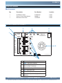
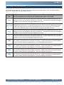
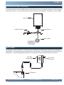
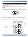
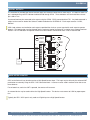
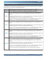
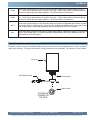
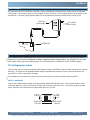
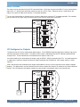
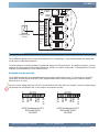
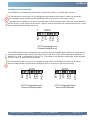
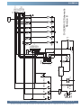
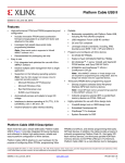
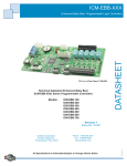
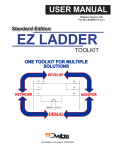
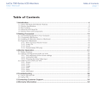
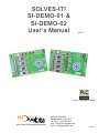
SOLVES-IT!
SI-DEMO-01 &
SI-DEMO-02
User’s Manual
REV .0
PLC on a Chip Patent 7,299,099
Smart Parts for Managing Automation
9778 Mt. Gilead Rd.
Fredericktown, OH 43019
Toll Free: 1-800-245-2327
Web: http://www.divelbiss.com
Email: [email protected]
2008001.0
Table of Contents
TABLE OF CONTENTS
Getting Started
How to Use this Manual
Page 2
Page 3
SI-DEMO-01
Package Contents
Getting to Know the SI-DEMO-01
TS1 Connection Descriptions
Installing a Solves-It! Plug-in PLC
Input Power
Digital Inputs
Digital Outputs
High Speed Counter
SI-DEMO-01 Schematic
Page
Page
Page
Page
Page
Page
Page
Page
Page
Page
4
5
5
6
7
7
8
9
10
11
SI-DEMO-02
Getting to Know the SI-DEMO-02
TS1 Connection Descriptions
Installing a Solves-It! Plug-in PLC
Input Power
Dual Function I/O
Digital Outputs
High Speed Counter
Analog Inputs
SI-DEMO-02 Schematic
Page
Page
Page
Page
Page
Page
Page
Page
Page
Page
12
13
14
15
16
16
18
18
19
22
Solves-It! Demo Board User’s Manual
Document #: 2008001.0.pdf
Page 1 of 23
Divelbiss Corporation 9778 Mt. Gilead Rd. Fredericktown, Ohio 43019 1-800-245-2327 www.divelbiss.com
GETTING STARTED
This section explains how to read this manual and understand the symbols.
Getting Started
HOW TO USE THIS MANUAL
In this manual, the following conventions are used to distinguish elements of text:
BOLD
Denotes labeling, commands, and literal portions of
syntax that must appear exactly as shown.
italic
Used for variables and placeholders that represent the type of text
to be entered by the user.
SMALL CAPS
Used to show key sequences or actual buttons, such as
the OK button.
OK,
where the user clicks
In addition, the following symbols appear periodically in the left margin to call the readers attention to specific details in
the text:
Warns the reader of a potential danger or hazard that is associated
with certain actions.
Appears when the text contains a tip that is especially helpful.
Indicates that the text contains information to which the reader
should pay particularly close attention.
All Specifications Subject to Change without Notice
Solves-It! Demo Board User’s Manual
Document #: 2008001.0.pdf
Page 3 of 23
Divelbiss Corporation 9778 Mt. Gilead Rd. Fredericktown, Ohio 43019 1-800-245-2327 www.divelbiss.com
SI-DEMO-01
This section describes the hardware features and options for the SI-DEMO-01 Solves-It! Demo Board. This
demo is designed for use with SI-100 and SI-200 Solves-it! Plug-in PLC models.
Use only the models approved for the SI-DEMO-01. Installing other Solves-It! models may damage the SolvesIt! and / or the Demo Board and void the warranty.
SI-DEMO-01
PACKAGE CONTENTS
What’s Included
Qty
1
1
1
Description
Part Number
Location
SI-DEMO-01 Board
Solves-It! Demo Board Manual
Wall-mount Power Pack
SI-DEMO-01
2008001.X
130-106047
In Box
In Box
In Box
GETTING TO KNOW THE SI-DEMO-01
3
2
1
PWR
4
GPO0
GPO1
5
GPO2
GPO3
CNT
Solves-It!
SI-DEMO-01
OFF
ON
+V
GPI0
COM
GPI0
GPI1
GPI1 / HSC
GPI2
6
GPI3
GPO0
GPI2
GPO1
GPO2
GPO3
GPI3
TS1
WWW.DIVELBISS.COM
7
1
TS1 - Input Terminal Connections
2
PWR - Input Power Indicator
3
CNT - High Speed Counter Momentary
Normally Open Pushbutton
4
GPO0-GPO3 - Output LED Indicators
5
VIN - Input Power Jack
6
Solves-It! Plug in Connector
7
GPI0-GPI3 - Input Normally Open Slide
Switches
Solves-It! Demo Board User’s Manual
Document #: 2008001.0.pdf
Page 5 of 23
Divelbiss Corporation 9778 Mt. Gilead Rd. Fredericktown, Ohio 43019 1-800-245-2327 www.divelbiss.com
SI-DEMO-01
TS1 CONNECTION DESCRIPTIONS
The SI-DEMO-01 provides the TS1 terminal connections block for accessing the Digital I/O of the installed Solves-It!
Plug-in PLC. Please refer to the descriptions for each.
+V
This terminal provides an access point for the power pack’s unregulated +12VDC supply.
COM
This terminal provides an access point for the COMMON of power pack’s output supply.
GPI0
This terminal connects directly to the GPI0 general purpose input of the installed Solves-It! Plug-in PLC.
Connecting this terminal to COM will cause the input to be true. The GPI0 slide switch on the SI-DEMO01 board must be turned off to allow proper operation of this pin.
This terminal connects directly to the GPI1 general purpose input and the High Speed Counter of the
installed Solves-It! Plug-in PLC. Connecting this terminal to COM will cause the input to be true. Each
GPI1 / HSC
transition from High to Low will cause the High Speed Counter to increment by one. The GPI1 slide
switch on the SI-DEMO-01 board must be turned off to allow proper operation of this pin.
GPI2
This terminal connects directly to the GPI2 general purpose input of the installed Solves-It! Plug-in PLC.
Connecting this terminal to COM will cause the input to be true. The GPI2 slide switch on the SI-DEMO01 board must be turned off to allow proper operation of this pin.
GPI3
This terminal connects directly to the GPI3 general purpose input of the installed Solves-It! Plug-in PLC.
Connecting this terminal to COM will cause the input to be true. The GPI3 slide switch on the SI-DEMO01 board must be turned off to allow proper operation of this pin.
GPO0
This terminal connects directly to the GPO0 general purpose output of the installed Solves-It! Plug-in
PLC. 12VDC will be present when the output is on or true. A 470Ω load resistor is installed to provide
the minimum load required for output operation. The GPO0 indicator will also be on.
GPO1
This terminal connects directly to the GPO1 general purpose output of the installed Solves-It! Plug-in
PLC. 12VDC will be present when the output is on or true. A 470Ω load resistor is installed to provide
the minimum load required for output operation. The GPO1 indicator will also be on.
GPO2
This terminal connects directly to the GPO2 general purpose output of the installed Solves-It! Plug-in
PLC. 12VDC will be present when the output is on or true. A 470Ω load resistor is installed to provide
the minimum load required for output operation. The GPO2 indicator will also be on.
GPO3
This terminal connects directly to the GPO3 general purpose output of the installed Solves-It! Plug-in
PLC. 12VDC will be present when the output is on or true. A 470Ω load resistor is installed to provide
the minimum load required for output operation. The GPO3 indicator will also be on.
Solves-It! Demo Board User’s Manual
Document #: 2008001.0.pdf
Page 6 of 23
Divelbiss Corporation 9778 Mt. Gilead Rd. Fredericktown, Ohio 43019 1-800-245-2327 www.divelbiss.com
SI-DEMO-01
INSTALLING A SOLVES-IT! PLUG-IN PLC
To install the Solves-It! into the SI-DEMO-01 board, align the Solves-It! over the provided connector. Ensure the polarity
‘notch’ aligns correctly. Firmly push the Solves-It! into the connector as far as possible. The Solves-It! is now installed.
Solves-It!
SI-DEMO-01 Board
Polarity Notch
Polarity Notch
SI-DEMO-01
CONNECTOR
TOP VIEW
INPUT POWER
The input power for the SI-DEMO-01 is included. Power is provided by a wall pack power supply with an unregulated
12VDC output. The wall pack plugs into any standard 115 VAC wall outlet. The cord plugs into the VIN connector on the
SI-DEMO-01. This power supply provides power for all on-board demo functions and the Solves-It! Plug-in PLC.
Wall Pack
Powersupply
TO 115VAC
Wall Outlet
GP O3
SI-DEMO-01
Solves-It!
SI-DEMO-01
V IN
Solves-It! Demo Board User’s Manual
Document #: 2008001.0.pdf
Page 7 of 23
Divelbiss Corporation 9778 Mt. Gilead Rd. Fredericktown, Ohio 43019 1-800-245-2327 www.divelbiss.com
SI-DEMO-01
DIGITAL INPUTS
There are two ways to control the digital inputs using the SI-DEMO-01 (inputs actually located on the installed SolvesIt!). The input can be enabled on-board using the provided slide switches for each or an external device connected to
TS1 can be used to drive the inputs.
The methods can be mixed, but any input using an external source must have the Slide switch turned OFF.
ON-BOARD
There are four slide switches located on the demo board, labeled GPI0 through GPI3. Each of these switches, when
closed, will apply the DC common to the Solves-It! digital input causing it to be On or True. Conversely, opening the
slide switch, opens the circuit and causes the digital input to be OFF or False.
OFF
ON
GPI0
SLIDE LEFT
FOR OFF
SLIDE RIGHT
FOR ON
EXTERNAL
The inputs may be connected using the TS1 connection block. Each input may be turned ON or True by connecting the
Input to the COM. Opening this connection makes the input turn OFF or False. Whatever device is used to drive the
inputs, must cause the input to be closed to COM for proper operation.
For any input connected to an external device, the input’s slide switch must be OFF for proper operation. The methods
can be mixed, but any input using an external source must have the Slide switch turned OFF.
PWR
GPO0
GPO1
CNT
OFF
+V
ON
GPI0
COM
GPI0
External Device
GPI1
GPI1 / HSC
GPI2
GPI3
GPO0
GPI2
GPO1
GPO2
GPO3
GPI3
TS1
Solves-It! Demo Board User’s Manual
Document #: 2008001.0.pdf
Page 8 of 23
Divelbiss Corporation 9778 Mt. Gilead Rd. Fredericktown, Ohio 43019 1-800-245-2327 www.divelbiss.com
SI-DEMO-01
DIGITAL OUTPUTS
The SI-DEMO-01 provides both status indicator and a terminal block connection for each output. The status of each output is indicated using red LED indicators labeled GPO0 through GPO3. These indicators are illuminated when the output is ON or True.
An external load may be connected to the output using the GPO0 - GPO3 connection block TS1. Any load connected is
subject to the maximum load of the Solves-It! model installed on the SI-DEMO-01. Each output sources +12VDC,
Nominal.
470Ω load resistors are installed on each output to provided the minimum current required for each output to operate
properly. This load resistor must be factored into the maximum load of the Solves-It! in relation to any external load connected. The LED indicators will operate whether an external load is connected or there is not an external load.
PWR
GPO0
GPO1
CNT
OFF
+V
ON
GPI0
COM
GPI0
GPI1
GPI1 / HSC
GPI2
GPI3
GPO0
External
LOAD
GPI2
GPO1
GPO2
GPO3
GPI3
TS1
HIGH SPEED COUNTER
GPI1 on the Solves-It! may also be used as a High Speed Counter Input. This input may be driven by the on-board CNT
push-button or externally using the GPI1 / HSC connection block. A counter must be used in software to be able to use
these features.
For on-board use, each time CNT is pressed, the counter will increment.
An external device may be used to drive the High Speed Counter. This device must connect to COM for proper operation.
Typically the GPI1 / HSC input is only used as a Digital Input or a High Speed Counter.
Solves-It! Demo Board User’s Manual
Document #: 2008001.0.pdf
Page 9 of 23
Divelbiss Corporation 9778 Mt. Gilead Rd. Fredericktown, Ohio 43019 1-800-245-2327 www.divelbiss.com
SI-DEMO-01
PWR
GPO0
GPO1
CNT
OFF
ON
+V
GPI0
PULL UP RESISTOR
COM
External Pulse
Device
GPI0
GPI1
GPI1 / HSC
GPI2
GPI3
GPO0
GPI2
GPO1
GPO2
GPO3
GPI3
TS1
Solves-It! Demo Board User’s Manual
Document #: 2008001.0.pdf
Page 10 of 23
Divelbiss Corporation 9778 Mt. Gilead Rd. Fredericktown, Ohio 43019 1-800-245-2327 www.divelbiss.com
Solves-It! Demo Board User’s Manual
Document #: 2008001.0.pdf
1
3
2
12VDC
VIN
+VA
GPI0
R1
1K
PWR
GPI1
GPI2
GPI3
CNT
+VA
R6
470
1
2
3
4
5
6
7
8
9
10
R7
470
GPO1
R3
1K
R8
470
GPO2
R4
1K
R9
470
SI-DEMO-01 Schematic
Revision B
GPO0
R2
1K
+V
COM
GP IO
GPI1 / HSC
GPI2
GPI3
GPO0
GPO1
GPO2
GPO3
TS1
GPO3
R5
1K
+VA
GPO1
GPO0
GPIO
GPI1 / HSC
GPI2
GPI3
EART H
- POWER
+ POW ER
GPO2
GPO3
JF
1
2
3
4
5
6
7
8
9
10
11
SI-DEMO-01
SI-DEMO-01 SCHEMATIC
Page 11 of 23
Divelbiss Corporation 9778 Mt. Gilead Rd. Fredericktown, Ohio 43019 1-800-245-2327 www.divelbiss.com
SI-DEMO-02
This section describes the hardware features and options for the SI-DEMO-02 Solves-It! Demo Board. This
demo is designed for use with SI-110, SI-120, SI-210 and SI-220 Solves-it! Plug-in PLC models.
Use only the models approved for the SI-DEMO-02. Installing other Solves-It! models may damage the SolvesIt! and / or the Demo Board and void the warranty.
SI-DEMO-02
PACKAGE CONTENTS
What’s Included
Qty
1
1
1
Description
Part Number
Location
SI-DEMO-02 Board
Solves-It! Demo Board Manual
Wall-mount Power Pack
SI-DEMO-02
2008001.X
130-106047
In Box
In Box
In Box
GETTING TO KNOW THE SI-DEMO-02
ON
GPI0
OFF
+V
9
GPO2
COM
0-10V
AI0
ACFG
SNG
0-5V
CNT
1
POT
DIF
INC
EXT
GPO4
GPIO2
GPI2
GPIO3 / HSC
GPO4
GPO5
GPO5
AIN TS1
GPI3
AIN +
6
WWW.DIVELBISS.COM
1
TS1 - Input Terminal Connections
2
PWR - Input Power Indicator
3
CNT - High Speed Counter Momentary
Normally Open Pushbutton
4
ACFG - Analog Input 0 Configuration Jumpers
5
VIN - Input Power Jack
6
Solves-It! Plug in Connector
7
GPIO0-GPI3 - Input Normally Open Slide
Switches
8
AI0 - Analog Input 0, On-board Potentiometer
9
GP00-GP05 - Digital Output Indicators
Solves-It! Demo Board User’s Manual
SI-DEMO-03
GPIO1
GPO3
GPI1
GPIO0
Solves-It! Analog
PWR
5
4
GPO0
1
8
GPO1
3
2
7
GPIO0 - GPIO3 are dual function
I/O Pins. They can be configured
as either inputs or outputs.
Function is controlled by the EZ
LADDER program.
Document #: 2008001.0.pdf
Page 13 of 23
Divelbiss Corporation 9778 Mt. Gilead Rd. Fredericktown, Ohio 43019 1-800-245-2327 www.divelbiss.com
SI-DEMO-02
TS1 CONNECTION DESCRIPTIONS
The SI-DEMO-02 provides the TS1 terminal connections block for accessing the Digital and Analog I/O of the installed
Solves-It! Plug-in PLC. Please refer to the descriptions for each.
+V
This terminal provides an access point for the power pack’s unregulated +12VDC supply.
COM
This terminal provides an access point for the COMMON of power pack’s output supply.
This terminal connects directly to the GPIO0 general purpose input / output of the installed Solves-It!
Plug-in PLC. This is a dual purpose I/O point. The Programming determines if this is an INPUT or an
OUTPUT.
GPIO0
As an input: Connecting this terminal to +V will cause the input to be true. The GPI0 slide switch on the
SI-DEMO-02 board must be turned off to allow proper operation of this pin.
As an output: 12VDC will be present when the output is on or true. A 470Ω load resistor is installed to
provide the minimum load required for output operation. The GPO0 indicator will also be on.
This terminal connects directly to the GPIO1 general purpose input / output of the installed Solves-It!
Plug-in PLC. This is a dual purpose I/O point. The Programming determines if this is an INPUT or an
OUTPUT.
GPIO1
As an input: Connecting this terminal to +V will cause the input to be true. The GPI1 slide switch on the
SI-DEMO-02 board must be turned off to allow proper operation of this pin.
As an output: 12VDC will be present when the output is on or true. A 470Ω load resistor is installed to
provide the minimum load required for output operation. The GPO1 indicator will also be on.
This terminal connects directly to the GPIO2 general purpose input / output of the installed Solves-It!
Plug-in PLC. This is a dual purpose I/O point. The Programming determines if this is an INPUT or an
OUTPUT.
GPIO2
As an input: Connecting this terminal to +V will cause the input to be true. The GPI2 slide switch on the
SI-DEMO-02 board must be turned off to allow proper operation of this pin.
As an output: 12VDC will be present when the output is on or true. A 470Ω load resistor is installed to
provide the minimum load required for output operation. The GPO2 indicator will also be on.
This terminal connects directly to the GPIO3 general purpose input / output of the installed Solves-It!
Plug-in PLC. This is a dual purpose I/O point. The Programming determines if this is an INPUT or an
OUTPUT.
As an input: Connecting this terminal to +V will cause the input to be true. The GPI3 slide switch on the
GPIO3 / HSC SI-DEMO-02 board must be turned off to allow proper operation of this pin.
As an output: 12VDC will be present when the output is on or true. A 470Ω load resistor is installed to
provide the minimum load required for output operation. The GPO3 indicator will also be on.
This terminal also connects to the High Speed Counter. It may be used as pulse or counter input.
Solves-It! Demo Board User’s Manual
Document #: 2008001.0.pdf
Page 14 of 23
Divelbiss Corporation 9778 Mt. Gilead Rd. Fredericktown, Ohio 43019 1-800-245-2327 www.divelbiss.com
SI-DEMO-02
GPO4
This terminal connects directly to the GPO4 general purpose output of the installed Solves-It! Plug-in
PLC. 12VDC will be present when the output is on or true. A 470Ω load resistor is installed to provide
the minimum load required for output operation. The GPO4 indicator will also be on.
GPO5
This terminal connects directly to the GPO5 general purpose output of the installed Solves-It! Plug-in
PLC. 12VDC will be present when the output is on or true. A 470Ω load resistor is installed to provide
the minimum load required for output operation. The GPO4 indicator will also be on.
AIN +
This terminal connects directly to the AI0 analog input of the Solves-It! Dependent upon Solves-It! model,
it will accpet 5VDC or 10VDC signals. This pin is either enabled or disabled as well as the mode of operation (Single-Ended or Differential) depending upon the configuration of the ACFG jumpers.
AIN -
This terminal either connects to the Solves-It! analog input negative in differential mode or is connected to
COM in Single-ended mode. The mode of operation (Single-Ended or Differential) depending upon the
configuration of the ACFG jumpers. .
INSTALLING A SOLVES-IT! PLUG-IN PLC
To install the Solves-It! into the SI-DEMO-02 board, align the Solves-It! over the provided connector. Ensure the polarity
‘notch’ aligns correctly. Firmly push the Solves-It! into the connector as far as possible. The Solves-It! is now installed.
Solves-It!
SI-DEMO-02 Board
Polarity Notch
Polarity Notch
SI-DEMO-02
CONNECTOR
TOP VIEW
Solves-It! Demo Board User’s Manual
Document #: 2008001.0.pdf
Page 15 of 23
Divelbiss Corporation 9778 Mt. Gilead Rd. Fredericktown, Ohio 43019 1-800-245-2327 www.divelbiss.com
SI-DEMO-02
INPUT POWER
The input power for the SI-DEMO-02 is included. Power is provided by a wall pack power supply with an unregulated
12VDC output. The wall pack plugs into any standard 115 VAC wall outlet. The cord plugs into the VIN connector on the
SI-DEMO-02. This power supply provides power for all on-board demo functions and the Solves-It! Plug-in PLC.
Wall Pack
Powersupply
TO 115VAC
Wall Outlet
GP O3
SI-DEMO-01
Solves-It!
SI-DEMO-01
V IN
DUAL FUNCTION I/O
The SI-DEMO-02 takes advantage of the SI-110, SI-120, SI-210 and SI-220 dual function I/O. Each of these Solves-It!
models has 4 I/O that can be configured as either a digital input OR a digital output. The SI-DEMO-02 allows operation of both modes (input and output) per point. The I/O configuration is controlled by the EZ LADDER program.
I/O Configured as Inputs
There are two ways to control I/O configured digital inputs using the SI-DEMO-02 (inputs actually located on the installed
Solves-It!). The input can be enabled on-board using the provided slide switches for each or an external device connected to TS1 can be used to drive the inputs.
The methods can be mixed, but any input using an external source must have the Slide switch turned OFF.
INPUTS - ON-BOARD
There are four slide switches located on the demo board, labeled GPI0 through GPI3. Each of these switches, when
closed, will apply the +12VDC to the Solves-It! digital input causing it to be On or True. Conversely, opening the slide
switch, opens the circuit and causes the digital input to be OFF or False.
OFF
ON
GPI0
SLIDE LEFT
FOR OFF
Solves-It! Demo Board User’s Manual
SLIDE RIGHT
FOR ON
Document #: 2008001.0.pdf
Page 16 of 23
Divelbiss Corporation 9778 Mt. Gilead Rd. Fredericktown, Ohio 43019 1-800-245-2327 www.divelbiss.com
SI-DEMO-02
INPUTS - EXTERNAL
The inputs may be connected using the TS1 connection block. Each input may be turned ON or True by connecting the
Input to the +V. Opening this connection makes the input turn OFF or False. Whatever device is used to drive the
inputs, must cause the input to be closed to +V for proper operation.
For any input connected to an external device, the input’s slide switch must be OFF for proper operation. The methods
can be mixed, but any input using an external source must have the Slide switch turned OFF.
AI0
ON
GPI0
OFF
INC
+V
GPO2
COM
GPIO1
GPO3
GPI1
GPIO0
External Device
GPO0
CNT
GPO1
PWR
GPO4
GPIO2
GPI2
GPIO3 / HSC
GPO4
GPO5
GPO5
AIN TS1
GPI3
AIN +
I/O Configured as Outputs
The dual function I/O may be configured at digital outputs. The SI-DEMO-02 provides both status indicator and a terminal block connection for each output. The status of each output is indicated using red LED indicators labeled GPO0
through GPO3. These indicators are illuminated when the output is ON or True.
An external load may be connected to the output using the GPIO0 - GPIO3 connection block TS1. Any load connected
is subject to the maximum load of the Solves-It! model installed on the SI-DEMO-02. Each output sources +12VDC,
Nominal.
470Ω load resistors are installed on each output to provided the minimum current required for each output to operate
properly. This load resistor must be factored into the maximum load of the Solves-It! in relation to any external load connected. The LED indicators will operate whether an external load is connected or there is not external load.
GPI0
+V
GPIO2
GPI2
GPIO3 / HSC
GPO4
GPO5
GPO5
AIN TS1
GPI3
AIN +
Solves-It! Demo Board User’s Manual
GPO3
GPI1
GPIO0
GPIO1
External
LOAD
ON
GPO2
COM
AI0
GPO0
OFF
INC
GPO1
CNT
GPO4
PWR
Document #: 2008001.0.pdf
Page 17 of 23
Divelbiss Corporation 9778 Mt. Gilead Rd. Fredericktown, Ohio 43019 1-800-245-2327 www.divelbiss.com
SI-DEMO-02
DIGITAL OUTPUTS
In addition to the dual function I/O, the SI-DEMO-02 provides access to the Solves-It! PLC’s two dedicated digital outputs. The SI-DEMO-02 provides both status indicator and a terminal block connection for both dedicated outputs. The
status of each output is indicated using red LED indicators labeled GPO4 and GPO5. These indicators are illuminated
when the output is ON or True.
An external load may be connected to the outputs using the GPO4 - GPO5 connection block TS1. Any load connected
is subject to the maximum load of the Solves-It! model installed on the SI-DEMO-02. Each output sources +12VDC.
470Ω load resistors are installed on each output to provided the minimum current required for each output to operate
properly. This load resistor must be factored into the maximum load of the Solves-It! in relation to any external load connected. The LED indicators will operate whether an external load is connected or there is not an external load.
GPI0
+V
GPIO2
GPI2
GPIO3 / HSC
GPO4
GPO5
GPO5
GPO3
GPI1
GPIO0
GPIO1
External
LOAD
ON
GPO2
COM
AI0
GPO0
OFF
INC
GPO1
CNT
GPO4
PWR
AIN TS1
GPI3
AIN +
HIGH SPEED COUNTER
GPIO3 on the Solves-It! may also be used as a High Speed Counter Input. This input may be driven by on-board CNT
push-button or externally using the GPIO3 / HSC connection block. A counter must be used in software to be able to
use these features.
For on-board use, each time CNT is pressed, the counter will increment.
An external device may be used to drive the High Speed Counter. This device must connect to +V for proper operation.
Typically the GPIO3 / HSC input should only be sued Digital Input / High Speed Counter OR a Digital Output.
Solves-It! Demo Board User’s Manual
Document #: 2008001.0.pdf
Page 18 of 23
Divelbiss Corporation 9778 Mt. Gilead Rd. Fredericktown, Ohio 43019 1-800-245-2327 www.divelbiss.com
SI-DEMO-02
INC
CNT
AI0
ON
GPI0
GPO1
OFF
+V
GPO2
COM
GPIO1
GPO3
GPI1
GPIO0
GPO4
GPIO2
GPI2
GPIO3 / HSC
External Pulse
Device
GPO0
PWR
GPO4
GPO5
GPO5
AIN TS1
GPI3
AIN +
ANALOG INPUTS
The SI-DEMO-02 provides easy access for the Solves-It! PLC’s analog input. Using the demo board, the analog input
can be source on-board and externally.
The analog features on the demo board are configured using the ACFG jumper block. By configuring jumpers, you may
configure the analog input as Single-ended, Differential, 0-5VDC or 0-10VDC analog input. The analog source is configured here as the on-board POT or an external source.
ON-BOARD ANALOG SOURCING
The SI-DEMO-02 provides an on-board potentiometer for a quick analog input source. To use this source, the ACFG
jumper block must be configured for POT, SNG (Singled-Ended) and the correct voltage for the model of installed
Solves-It! (0-5V or 0-10V).
Verify the correct Voltage Setting on the AFCG jumper block for the model Solves-It! installed. Incorrect voltage settings
may damage the SI-DEMO-02 and / or the Solves-It! and void the warranty.
Solves-It! Demo Board User’s Manual
0-10V
SNG
0-5V
ACFG
POT
DIF
0-10V
SNG
0-5V
ACFG Configured for POT,
SNG and 0-5VDC
SOURCE
EXT
1
ACFG
POT
DIF
EXT
1
ACFG Configured for POT,
SNG and 0-10VDC
SOURCE
Document #: 2008001.0.pdf
Page 19 of 23
Divelbiss Corporation 9778 Mt. Gilead Rd. Fredericktown, Ohio 43019 1-800-245-2327 www.divelbiss.com
SI-DEMO-02
EXTERNAL ANALOG SOURCING
The SI-DEMO-02 may also be sourced externally using the AIN- and AIN + connection block terminals.
The sourcing device and wiring, the AFCG configuration jumper block and the Solves-It! model must be correct.
Incorrect voltage settings may damage the SI-DEMO-02 and / or the Solves-It! and void the warranty.
To be able to use an external source, the ACFG jumper block must be configured at EXT (External). When configured
as EXT, the 0-5V / 0-10V jumper has no function. Verify the external source does not exceed the Solves-It! PLC’s analog input specifications or damage may result.
0-10V
SNG
0-5V
ACFG
POT
DIF
EXT
1
ACFG Configured for an
External Analog Source
The SI-DEMO-02 board can be configured for the external source to be Singled-Ended or Differential. When ACFG is
configured as Singled-Ended, it connects the Solves-It! PLC’s AIN- to the COM. When configured as Differential, the
Solves-It! PLC’s AIN- is connected to the AIN- on TS1. This provides a true differential analog input. When configured
as EXT, the 0-5V / 0-10V jumper has no function.
The sourcing device and wiring, the AFCG configuration jumper block and the Solves-It! model must be correct.
Incorrect voltage settings may damage the SI-DEMO-02 and / or the Solves-It! and void the warranty.
Solves-It! Demo Board User’s Manual
0-10V
SNG
0-5V
ACFG
POT
DIF
0-10V
SNG
0-5V
ACFG Configured External
Source and Single-Ended
EXT
1
ACFG
POT
DIF
EXT
1
ACFG Configured External
Source and Differential
Document #: 2008001.0.pdf
Page 20 of 23
Divelbiss Corporation 9778 Mt. Gilead Rd. Fredericktown, Ohio 43019 1-800-245-2327 www.divelbiss.com
SI-DEMO-02
To use an external source, it must be wired to the TS1 AIN+ and AIN - terminals for differential or the TS! AIN+ and
COM for Single-ended.
GPO0
GPO4
-
+
AIN TS1
GPO1
GPO3
GPIO1
GPIO2
GPIO3 / HSC
GPO4
GPO5
AIN +
GPI3
AIN +
GPI1
GPIO0
External AIN
Source
GPO5
GPO5
GPO2
COM
GPO4
GPIO3 / HSC
GPI0
+V
GPO5
GPIO2
GPI2
+
ON
GPI2
GPIO1
GPO3
External AIN
Source
GPI1
-
GPIO0
AI0
OFF
GPO2
COM
INC
CNT
AIN TS1
Single Ended External
Analog Source
GPI3
+V
PWR
GPO1
ON
GPI0
OFF
AI0
GPO0
INC
CNT
GPO4
PWR
Differential External
Analog Source
A 0-20mADC or 4-20mADC input signal may be used with the addition of an external resistor connected from the AIN+ to
the AIN- terminal. For a 0-5VDC Solves-It!, use a 249Ω resistor. For a 0-10VDC Solves-It!, use a 499Ω resistor.
Solves-It! Demo Board User’s Manual
Document #: 2008001.0.pdf
Page 21 of 23
Divelbiss Corporation 9778 Mt. Gilead Rd. Fredericktown, Ohio 43019 1-800-245-2327 www.divelbiss.com
Solves-It! Demo Board User’s Manual
Document #: 2008001.0.pdf
1
3
2
12VDC
VIN
+VA
PWR
R1
1K
C1
0.33uF
GPI0 GPI1 GPI2 GPI3
1
IN
U1
CNT
A DJ
OU T
LM317LZ
R8
365
0-10V
S NG
0-5V
POT
D IF
EX T
1
2
3
4
5
6
7
8
9
ACFG
1.02K
2.49K
R10
R9
C2
0.33uF
R11
470
GPO0
R2
1K
+V
COM
GP IO0
G POI1
G PIO2
GPIO 3/ HSC
GPO 4
GP O5
A IN+
AIN -
TS1
1
2
3
4
5
6
7
8
9
10
+VA
R3
1K
A IO
1K
GPO1
R1 2
470
GP O3
R5
1K
R14
470
GP O4
R6
1K
R15
470
GPO5
R7
1K
R16
470
GP IO2
GPIO 3/H SC
GPO4
GP O5
A IN A IN +
EA RTH
- P OW ER
+ P OWE R
GP IO0
G PIO1
JF
1
2
3
4
5
6
7
8
9
10
11
SI-DEMO-02 Schematic
Revision B
GPO2
R4
1K
R 13
470
+VA
SI-DEMO-02
Page 22 of 23
Divelbiss Corporation 9778 Mt. Gilead Rd. Fredericktown, Ohio 43019 1-800-245-2327 www.divelbiss.com
Limited Warranty
Divelbiss Corporation warrants equipment will be free from defects in material and workmanship for
a period of one (1) year from the date of the Divelbiss invoice that the equipment was furnished.
Divelbiss Corporation will not be liable for any design furnished by Buyer and incorporated into the
equipment.
In no event shall Divelbiss Corporation be liable for anticipated profits, consequential damages or
loss of use of equipment or of any installation into which the equipment covered by this order may
be put.
Divelbiss Corporation shall not be liable or responsible for any loss, injury, or damage resulting
directly or indirectly from the use of software and/or programming in any way associated with the
equipment of this order.
Obligations are to be limited to the repair or replacement at the Divelbiss Corporation plant,
Fredericktown, Ohio, upon return of the part or component in question, prepaid by Buyer. The return
freight charges to be paid by Divelbiss. The part or component is only to be returned to Divelbiss
with a Returned Material Authorization number issued by the Divelbiss Service Department. Any
warranty service (consisting of time, travel, and expenses related to such services) performed other
than at Divelbiss Corporation plant, shall be at Buyer's expense.
Warranty of repaired or replacment products will be limited to ninety (90) days or the remainder of
the original warranty whichever is greater.
Warranty is available only if Divelbiss Corporation is promptly notified in writing upon discovery of
any alleged defect and examination of the subject product discloses, to Divelbiss satisfaction, that
any defect has not been caused by misuse; neglect; improper installation; improper operation;
improper maintenance, repair, or alteration; accidents; or unusual deterioration or degradation of the
equipment or parts thereof due to physical environment or due to electrical or electromagnetic noise
environment.
This warranty is in lieu of all other warranties, expressed, implied, or statutory, including warranties
of merchantability or fitness for a specific purpose.