1
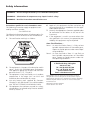
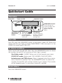
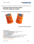
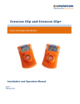
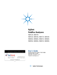
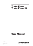
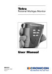
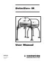
Detective+ IR
User Manual
M07663
June 2010
Issue 4
Safety information:
WARNING – Do not change the battery in a flammable atmosphere.
WARNING – Substitution of components may impair intrinsic safety.
WARNING – Read the instruction manual before use.
Instructions specific for use in hazardous areas
6. Repair of this equipment shall be carried out by
The following instructions apply to equipment covered by certificate number:
the manufacturer or in accordance with the applicable code of practice.
7. Use only the appropriate Crowcon supplied cables
for connection to the sockets at the rear of the
instrument.
8. If the equipment is used in a manner other than
that specified in this manual, the protection provided by this equipment may be impaired.
Sira 03ATEX2102
The following information covers all relevant points listed in clause 1.0.6 of the EHSR’s of the ATEX directive.
1. The certification marking is as follows:
Area Classifications: Zone 1: An area classified as Zone 1 is likely to have
ignitable concentrations of flammable gases,
vapours or liquids present under normal operating conditions.
Zone 2: An area classified as Zone 2 is not likely to
have ignitable concentrations of flammable
gases, vapours or liquids present under normal operating conditions.
2. The equipment is Category 2G and may be used in
zones 1 and 2 with flammable gases and vapours
with apparatus groups IIA, IIB & IIC and with temperature classes Tl, T2, T3 and T4
3. The equipment is only certified for use in ambient
temperatures in the range -20°C to +50°C and
should not be used outside this range
4. Use only battery pack supplied by Crowcon.
Charging is only permitted in the non-hazardous
area. DO NOT CHARGE IN HAZARDOUS AREA.
5. The equipment has not been assessed as a safetyrelated device (as referred to by Directive 94/9/EC
Annex II, clause 1.5)
Crowcon Detection Instruments Ltd
2 Blacklands Way, Abingdon
OX14 1DY UK
Tel. +44 (0)1235 557700
Fax. +44 (0)1235 557749
www.crowcon.com
Email: [email protected]
© Copyright Crowcon Detection Instruments Ltd 2010.
All rights are reserved. No part of the document may be
photocopied, reproduced, or translated to another language
without the prior written consent of Crowcon Detection
Instruments Ltd.
Publication number: M07663
Fourth edition: June 2010
Contents
Quickstart Guide....................................................................1
I. General Description.........................................................3
II. Unpacking.......................................................................5
III. Operation........................................................................7
3.1 Switch On.........................................................................................7
3.2 Display..............................................................................................8
3.3 Overrange.........................................................................................9
3.4 Cautions.........................................................................................10
3.5 Backlight.........................................................................................10
3.6 Alarms............................................................................................10
3.7 Status Screens/Alarm Reset . ...........................................................10
3.8 Switching Off..................................................................................11
IV. Setting Up ....................................................................12
4.1 Using the Menu system...................................................................12
4.2 Configuration Options ...................................................................15
4.3 Quickcal..........................................................................................19
V. Battery Charging...........................................................20
VI. Data Logging.................................................................22
VII. Interconnection Between Devices...................................23
VIII.Troubleshooting Guide...................................................24
IX. Maintenance and Calibration.........................................25
9.1 Recalibrating...................................................................................25
9.2 Replacing the Battery Pack..............................................................25
9.3 Replacing a Sensor Module.............................................................26
9.4 User Replaceable Fuses....................................................................27
X. PC interface and software..............................................28
XI. Limitations of Use..........................................................29
XII.Specification..................................................................30
XIII.Accessories and spares...................................................31
Appendix 1 – Pumped version (optional)..............................33
Appendix 2 – Front Panel Text Items....................................34
Appendix 3 – Sensor Limitations..........................................36
Appendix 4 – Menu Map.....................................................37
Detective+ IR
QuickstartSection
Guide
Quickstart Guide
Overview
Alarm LED
Power On LED
Operator screen
UNMARKED button:
use this button to
silence sounder, reset
alarm and select
options from the
Menu
ON button
BACKLIGHT
button
Switch-off:
press the ON button
and UNMARKED
button together to
switch off
CAL button:
use this button to
perform calibration
and access unit's
configuration
Turn ON
Press ON, press the UNMARKED button to reset alarm, green LED flashes and
display will show gas levels or display 'MONITORING' if the instrument is in the
GO/NO-GO mode (see SETTING UP).
In Alarm condition
Alarm sounds and the red LEDs flash. Press the UNMARKED button to silence
the sounder, the red LED will continue to flash if gas is present.
Gas display mode: 'ALARM' flashes next to the hazardous gas name.
GO/NO-GO mode: display reads 'GAS HAZARD, EVACUATE AREA'.
Instantaneous and TWA alarms: Alarm is triggered when the instantaneous threshold is reached. Press the UNMARKED button to silence the
sounder, the red LEDs will continue to flash if gas is present. The sounder
will be triggered again if a new alarm threshold is reached.
Reset Alarm
Press the UNMARKED button.
Section Guide
Quickstart
Detective+ IR
Turn On Backlight
Press the BACKLIGHT button
. It stays on for 30 minutes unless the button
is pressed again. This is programmable, but is 30 minutes by default.
Battery Low
Green LED flashes quickly, the sounder frequency increases and a warning is
flashed on the display. Use charger lead to charge the unit (8 hours for a full
charge).
Warning: Charge the unit in a Safe area only.
Calibration/Setting up
Pressing 'CAL' and entering a password enables the instrument to be recalibrated and to change its operating modes and configuration.
Detective+ IR
General Description
I. General Description
The Crowcon Detective+ is a microprocessor controlled transportable gas detector which is capable of monitoring up to four gas types simultaneously and
providing warning of hazardous levels. See Appendix 3 for notes on sensor
limitations.
The built in data logging facility records gas levels of all four channels at user
definable intervals for subsequent downloading to a computer. This enables a
more detailed evaluation of accumulated exposure to be made than is possible
with the Time Weighted Average exposure integrator, and may yield useful data
about gas leak patterns and can provide essential information to an incident
inquest.
The Detective+ IR unit is designed for temporary monitoring of working areas
where hazardous gases may be present. For small area monitoring, while
personnel are working, a single unit can be used. For protecting larger areas
a number of Detective+ IR units can be interconnected, providing a protective perimeter around the work area. (See section 6 for details on how to link
Detective+ IR units together).
Presence of hazardous gas levels is indicated by three high intensity red light
beacons on the top of the unit and a high volume audible sounder on the
underside of the unit.
The main body of the unit is constructed from fire retardant, high impact, UV
stabilised ABS plastic and is protected against water and dust ingress to IP65.
The unit can be supplied with either a rugged steel tripod frame or a rigid composite tripod frame with hinged legs for space-saving storage.
The sensors are located on the underside of the unit for protection, a manual
aspirator can be attached for spot sampling. A pump option for automatic sampling is available. The Sealed Lead Acid battery pack within the unit provides
power for up to 36 hours of continuous operation including a 30 minute period
in alarm mode.
Detective+ IR is a specific version of the Detective+ utilising an infrared sensor
for the detection and measurement of hydrocarbons, in place of the conventional pellistor sensor. Using infrared technology in place of pellistor technology
has a number of advantages as follows:
(a) No requirement for oxygen in the background gas i.e. operation in
inert backgrounds
General Description
Detective+ IR
(b) No damage caused by exposure to high gas concentrations
(c) No poisoning effects
(d) Ability to measure at % volume levels as well as %LEL
(e) Fail safe
It must be remembered however that an infrared hydrocarbon sensor will have
no response to hydrogen and is therefore unsuitable for use where hydrogen
forms a significant part of any potential flammable risk. In order to ensure ready
identification of Detective+ IR the membrane switch assembly is yellow in place
of the normal orange and carries the name designation ‘Detective+ IR’.
The infrared sensor module in Detective+ IR will be supplied with a calibration
for one of four hydrocarbon species i.e. methane, propane, butane or ethylene.
This calibration is factory set. Whatever the calibrated species the infrared sensor will respond to any hydrocarbon present, but with differences of response
to different species. However unlike for a pellistor sensor it is not possible to
assign simple correction factors, as the basic relationship between concentration and response of the detector is not linear. An infrared sensor should
therefore always be calibrated for the species to be determined or a suitable
target. If other specific hydrocarbon species need to be detected, please consult
Crowcon as to the optimum calibration.
The infrared sensor in Detective+ IR can be supplied on one of two configurations as follows:
• Single range %LEL
In this case the Detective+ IR can have up to three other sensors from the standard range of toxic and oxygen sensor modules available.
• Dual range %LEL and % volume
In this case the sensor module has a second ribbon connector on a side-piece of
PCB, and therefore takes up two display positions on Detective+ IR. This allows
only two other sensor modules from the toxic and oxygen range to be used.
A dual range sensor will always have both ranges calibrated for the same species, and operates in an auto-ranging mode displaying in %LEL terms with no
numerical display for % volume until the level of gas exceeds 100%LEL, and in
volume terms with no numerical value for %LEL when the level of gas is above
100%LEL. Note also the lower range will always display as %LEL even if the
gas is detected in an inert background gas where strictly speaking the mixture
cannot be explosive. The display indicates the equivalent %LEL level if the gas
were in an air background.
Note: It is not possible to have a pellistor or thermal conductivity sensor in a
Detective+ IR.
Detective+ IR
Unpacking
II. Unpacking
The Detective+ IR can be supplied with either a rigid steel tripod or a hinged
composite tripod designed to be folded away for storage.
When unpacking the steel framed Detective+ IR for the first time, the three
legs must be attached to the main body of the units’ frame, using the bolts
provided.
When unpacking the composite framed Detective+ IR for the first time, the
three legs will be in the folded position.
Unpacking
Section
Detective+ IR
To unfold the legs
a) pull the leg upwards until it reaches its stop,
b) r otate the leg downwards away from the instrument until it is pointing
downwards,
c) push the leg upwards until it firmly fits into position.
a)
b)
c)
If the legs are too loose or are required to be permanently
deployed, gently tighten the fixing bolt at the leg hinge.
Similarly, if the leg joint is too tight simply loosen the fixing bolt at the leg hinge, but dot not loosen it too far.
When packing the unit away, simply reverse the above
procedure.
When the legs are in the folded position the Detective+ IR is
designed to be stacked one upon
the other, but it is recommended
no more than three units at a
time are stacked together.
Units MUST NOT be stacked in this fashion during transportation unless they are
otherwise suitably secured.
When stacking units the user must be careful to comply with local
health and safety regulations.
Detective+ IR
Operation
Section
III. Operation
3.1 Switch On
Ensure the unit is in clean air. Press the 'ON' button to switch on the
Detective+ IR. The instrument will display the message 'Crowcon Detective+
IR' and the serial number. The unit will test the red alarm LED, sounder and
alarm beacons. Press the UNMARKED button to silence the alarm. Note: if the
unit is in the presence of a hazardous gas the alarm will continue to operate. If
alarms are configured to mute (see MUTE in section 4.2, Configuration Options)
then the alarm will not sound and the alarm LED not flash during the switch
on process.
After a short pause the display will change to 'Testing System…' and display
the current battery voltage. If the current date is past a preset calibration due
date, then the instrument will display ‘Calibration Due’. See section 3.6 for
configuration options. If there are different sensor modules in the instrument
compared to when it was last used (possibly indicating sensor failure) the message 'Sensors changed?' will be displayed. If the instrument’s configuration
has been lost or corrupted, then the message 'Loading default data' will be
displayed. With all three of these error/warning messages, the condition must
be accepted by pressing the UNMARKED button, indicated on the display with
the word CONTINUE above it.
Calibration due?
Continue
The instrument can alarm on instantaneous gas levels, and on both short and
long term Time Weighted Average gas exposure levels. Note that the Time
Weighted Average toxic gas exposures are reset to zero when the instrument
is switched off.
When the battery reaches a low level, an operational unit will display a low battery warning. Note: if the battery is too low the unit will not switch on.
Operation
Detective+ IR
About 10 seconds after the instrument is switched on, the Detective+ IR will
complete its self-tests and indicate the current gas levels.
If the instrument enters an alarm condition then the sounder will be triggered and the alarm LEDs will flash. Once the gas levels are below alarm levels
(i.e. safe gas levels), the alarm warning may be switched off by pressing the
UNMARKED button. If alarms are muted the red alarm LED will not flash nor
will the alarm sounder sound when the instrument is in alarm - the only indication of the alarm condition will be the word ‘ALARM’ alternately flashing with
the gas value of the channel in alarm.
3.2 Display
The information on the display is dependent on the type of sensors installed
in the instrument. For each sensor module installed, the display indicates the
gas concentration, the units of measurement (e.g. ppm) and the channel name
(e.g. H2S). (Each sensor module contains analogue circuitry to support the sensor and a small digital memory which identifies it to the processor along with
calibration data and alarm thresholds.) A quarter of the screen is reserved for
each of a possible 4 gas channels. The normal mode of operation is continuous
real-time gas concentration.
H2S 0.0 ppm
CO 0.0 ppm
CH4 0.0 %LEL
O2 20.9 %
Confidence signals
The green ‘power’ LED flashes intermittently to give confidence to the user that all is
as it should be.
Detective+ IR
Operation
Section
Display options
The instrument may be configured into alternative display modes, by the DISPY
option (see DISPY in section 4.2, Configuration Options). The ON button can
be programmed to switch between modes.
The possible display modes are:
Normal: All gas values, units and names are displayed in real time
Average: The average gas reading since the instrument was switched on is
displayed for toxic sensors. This is indicated by flashing 'avg' with
the sensor name. Non-toxic sensors will display their normal gas
level.
Off: Display reads 'MONITORING' whilst a safe condition is perceived,
and flashes 'GAS HAZARD and EVACUATE AREA 'in alarm condition.
TWA Toxic: This display mode only affects toxic sensors, and is indicated by
the letters 'TWA' flashing with the sensor name. The gas value
displayed will be the current long-term exposure level. Non-toxic
gas sensors will display their normal gas level.
Peak hold: This options affects the displayed gas value for all sensors, and is
indicated by the letters 'pk' flashing with the sensor name. The
highest gas level that has been read since instrument switch on
will be displayed, or in the case of oxygen, the lowest level read.
The peak that has been retained may be reset to the current gas
level by pressing the UNMARKED button. The peak gas level will
then be displayed again from then on.
In addition to the messages described above, if alarms are muted the message
‘MUTED’ will flash with the sensor name and units.
3.3 Overrange
If a flammable sensor’s signal is out of range then the instrument may be configured, via a PC and the Portables PC software, to either flash the relevant
numbers on the display, or to display a message of the form 'SENSOR FAILURE'
and the name of the failed sensor. The alarm sounder will activate. This type
of error could indicate a high gas level or sensor failure. Calibration should be
checked after such a warning.
Section
Operation
Detective+ IR
3.4 Cautions
Sensors may be adversely affected by exposure to silicones, lead compounds,
high levels of hydrogen sulphide and chlorine, and some industrial solvents.
3.5 Backlight
In low ambient light conditions, the backlight can be activated to illuminate
the display by pressing the BACKLIGHT button
. To switch off the backlight
press the BACKLIGHT button again, or it will turn off automatically after a
configurable timeout period of 10, 20 or 30 minutes. Alternatively, the backlight may be configured to remain on permanently, or to never timeout once
switched on. (See LIGHT in section 4.2, Configuration Options). In an alarm
condition, the backlight is automatically turned on.
3.6 Alarms
When the Detective+ IR encounters an alarm condition the red lights flash, the
beacons activate and the sounder emits a loud, fast bleep. Where permitted
instantaneous toxic gas alarms may be accepted by pressing the UNMARKED
button. In this case, the sounder is silenced but the red lights continue to
flash. With instantaneous alarms, the word 'ALARM' will flash next to the
gas name. Time Weighted Average exposure limit alarms will flash the whole
display with the warning. All instantaneous alarm types are latching which
means that they may only be reset by pressing the UNMARKED button when
the gas hazard has passed. If set up for time weighted average (TWA) alarms,
the Detective+ IR triggers a non-resettable alarm if a short term (normally 15
minute) or long term (8 hour) exposure level is reached. Both TWA alarm types
may only be reset when the average exposure has fallen below threshold levels.
(See Configuring the instrument with Portables PC software on setting these
levels).
3.7 Status Screens/Alarm Reset
The UNMARKED button has two functions: to reset alarms (see 3.6 above)
or to display a series of status screens. To view the status screens press the
UNMARKED button when the instrument is not in an alarm condition.
The series of status screens show the following information in sequence. Press
the UNMARKED button to move onto the next screen, and eventually back to
the main instrument display of gas levels. If the button is not pressed for 20 seconds the instrument will ‘timeout’ and return to the main gas reading screen.
10
Detective+ IR
Operation
Section
The date, current time, and the time elapsed since instrument switch
on is displayed.
Serial number and calibration due date is displayed.
Alarm 1 levels are shown for all sensors.
Short-term exposure levels are displayed for toxic sensors.
Long-term exposure levels are displayed for toxic sensors.
Currently selected user and site are displayed.
3.8 Switching Off
Before turning the unit OFF, purge it with air, until all channels read zero and
Oxygen reads 20.9%, after this turn it of. The DETECTIVE+ is turned OFF by
simultaneously pressing the ON button and the UNMARKED button simultaneously and holding them down for about half a second. This prevents accidental
switch off through knocking the keypad. This ‘OFF’ mode may be disabled via
the Menu or using the Portables PC software.
If the unit is not purged and has gas inside, the next time it is turned on and
zeroed, it will zero in gas presence. In this case, after the gas is purged, the
detector will give negative readings. If this happens, purge the unit until it stabilize at a negative reading, then do a manual zero according to section 4.2.
11
SectionUp
Setting
Detective+ IR
IV. Setting Up
The Detective+ IR has been designed to display as much or as little information
to the user as is required by the controller of the equipment. On the one hand it
is a four channel measuring instrument with continuous readout, on the other,
a basic alarm only detector with status display and no way of switching it off.
This section describes how to tailor the instrument to the application via the
front panel buttons. The section on Configuring the instrument with Portables
PC details other adjustments that may be made to the instrument configuration
via a PC and the Portable PC software.
4.1 Using the Menu system
To access the SETUP menu press ‘CAL’ button. The screen will display the
following:
As the menu is
Buttons act
as 'soft key'
functions
MENU
<<
Scroll menu list
to the left
Scroll menu list
to the right
EVENT
LOG
>>
QUIT
LOG
Quit menu and
return to normal
gas reading screen
scrolled left or right,
the menu item
here will appear
as the 'soft key'
option above the
UNMARKED button
Select Menu option
currently indicated.
This will change as
Menu is scrolled.
The four buttons have above them a symbol or word: these are the ‘soft key’
functions currently assigned to that particular key. Use the ON and BACKLIGHT
buttons to scroll left and right, the CAL button to quit the menu system and
the UNMARKED button to select a menu option. View the road map on page
37 for details of Detective+ IR configuration menu system
The options available are:
MENU This selects the configuration menu. It is password protected, and
described below
EVENT This marks an event in the data log. There is no menu beneath this
option.
LOG This selects the log menu, described below.
12
Detective+ IR
Setting
Section
Up
How to enter the configuration Menu
Use the scroll buttons to select the MENU item and press the UNMARKED
button. The screen will display 'Password?' Press the buttons in the following
sequence within 5 seconds to enter the default password: ON, BACKLIGHT, CAL
and UNMARKED. This password can be changed via a PC and the SetPortable
software.
1
2
3
4
How to change an option
To change an option, use the first two keys, labelled with the << and >> symbols, to change the current selection, and the third key (labelled QUIT) to finish
changing the selection. If the QUIT key is pressed and the parameter has been
modified then the user is prompted with a save changes message. Two keys
are soft key function labelled, one with YES and one with NO. Press the desired
button.
For example, to configure the start-up option, from the configuration Menu
follow the steps below:
DISPY ALARM ZERO PUMP
<<
>>
QUIT
PUMP
Scroll the menu
list to the left until
START is selected
ALARM ZERO PUMP START
<<
>>
QUIT
START
Press the
UNMARKED button
to enter the START
submenu
13
SectionUp
Setting
Detective+ IR
START : ZERO & LOG
<<
>>
QUIT
Use these buttons to scroll
through options (Section 4.2)
Press the CAL button
to select option and
QUIT menu
Save the changes made?
YES
NO
Press the first button to save the change and move the menu back up a level,
and the last key to leave the selection as it was (unchanged) and move back
up a level.
The menu system has timeouts on all operations. If no keys are pressed within
about 20 seconds the system steps back one level at a time. Changes that have
been accepted by pressing YES to the save changes prompt are retained. Any
change that has not been explicitly saved will be lost.
The following parameters are modifiable via the instrument front panel buttons, and are displayed on the screen in the following order:
ZERO FLAMM LEVEL PUMP CALIB DISPY ALARM START BUTTN TIME
OFF LIGHT
Details of each parameters are given in section 4.2, a road map of the menu
system can be found on page 37.
14
Detective+
Detective+ IR
IR
Configuration Options
Section
4.2 Configuration Options
LIGHT:
Configures the backlight timeout option to be NEVER TIMEOUT, 10 MINS.,
20 MINS., 30 MINS., or ALWAYS ON. Whatever option is selected, the backlight
will always come on when the instrument is in alarm.
DISPY
Display mode. Configures the instrument display mode, with one of the following options: Normal, Average, Off, TWA Toxic, Peak Hold. These are described
in the section III Operation. Note: the action of the BUTTN option below.
ALARM
Alarm mode. User can select one of the following: ALL ACTIVE, TWA ONLY,
INSTANT.
Within this option, the instrument may be set up to acknowledge different toxic
gas alarm types. Instantaneous mode (INSTANT) sets the instrument to alarm as
soon as threshold toxic gas level is reached.
TWA ONLY will cause the instrument to ignore temporary excursions above
instantaneous alarm thresholds but to go into alarm instead when the SHORT
TERM or LONG TERM exposure levels have been reached. ALL ACTIVE enables
both TWA and instantaneous alarm types but allows the user to silence instantaneous alarms (see section III Operation).
‘ZERO’
When this option is selected, the instrument will give the prompt ‘ZERO ALL?’
Only if you are sure that the instrument is in clean air and all sensors have settled down to a steady output should YES be pressed. The Detective+ IR then
calculates offset correction and gain factors necessary to make toxic and flammable gas channels read zero and oxygen channels read 20.9%. Following a
successful zeroing, there is the option to END the set up and return to monitoring, or to CONT to continue with setting up.
PUMP
Turns the pump on and off. Options are GO and STOP.
START
Selects functions to be enabled at start up (instrument switch on). Options are:
NOTHING, ZERO, LOG, ZERO & LOG.
15
Configuration
options
Section
Detective+
Detective+ IR
IR
ZERO enables the option of zeroing the sensors at start, as per the zero all
option above – the prompt to zero the sensor will appear several seconds after
start up (to give the sensors time to settle) and will timeout (without performing
a zero) if the YES button is not pressed within about 5 seconds.
LOG enables data logging at start up, and ZERO & LOG enables both zero and
data logging at start up. Select NOTHING to disable zero and logging at start
up.
BUTTN
The ON button can be programmed to perform various functions when the
instrument is in normal gas measurement mode. The options available are:
NOTHING, PUMP, PEAK, TWA TOXIC, AVERAGE, NORMAL.
NOTHING means all special functions on the button are disabled.
PUMP allows the pump to be switched off and on without having to enter the
menu system to perform this action.
PEAK, TWA TOXIC and AVERAGE are as per the DISPY functions. Pressing the
button when one of these options is selected will toggle the display mode
between that set on the button and that set in the DISPY setting.
NORMAL serves a similar function. If the DISPY mode has been set to something other than NORMAL then NORMAL allows the display mode to be toggled from that set in the DISPY option to the normal gas display. Note: these
display functions have no effect if the DISPY mode is set to OFF, and that the
instrument will always start up in the display mode set by the DISPY function.
If the MUTE function is enabled then a SILENT ALARMS option will also appear
as one of the possible selections in the BUTTN menu. This option allows the
programmable button to toggle the MUTE feature between SILENT ALARMS
and AUDIBLE ALARMS. Note that when SILENT ALARMS is selected no audible
siren will sound when the instrument is in alarm, nor will the alarm light flash.
There will be a visual indication of the alarm condition on the instrument’s
display. When the programmable button is pressed the instrument will issue a
double bleep sound as an audible confirmation that a feature has been selected
or de-selected.
FLAMM
This is not functional in Detective+ IR.
16
Detective+ IR
Configuration options
Section
CALIB
This allows re-calibration of the instrument, which must first have been Zeroed
in clean air. You will need a calibration flow plate, which is included as standard
with the Detective+ IR and a supply of Crowcon calibration gas (see section
VIII Maintenance and Calibration). The top line now displays one of the instrument’s gas channels. This display will look like:
CALIBRATE: CH4 (Chan.1)
<<
>>
QUIT
CAL
Use the first two keys to select the required gas. Press QUIT to move back up a
menu level, or CAL to select the gas to calibrate. The display will now change
to:
CALIBRATE: CH4 = 0
UP DOWN QUIT
CAL
The actual gas reading is displayed on the top line, and should go up when the
relevant TEST GAS is aspirated over the sensors. When the reading has stabilised use the UP and DOWN keys to make the reading match the known test
gas concentration. Now press CAL to actually calibrate the instrument’s gain.
QUIT can be pressed to abandon the calibration. If the instrument is calibrated,
it will either respond with CAL SUCCESSFUL or CAL FAILED. If the calibration
failed the instrument’s gain is not changed, and means that either the gas concentration was not equal to the value set (check both and repeat) or that the
sensor has deteriorated with use (see Maintenance and Calibration for sensor
replacement).
When a calibration is being performed, replace the integral flow plate with the
calibration flow plate so the gas is not being sampled by the pump.
TIME
Selecting this will give a display of the form:
CURRENT TIME: 21:48:00
HOUR MINUTE QUIT
17
Section
Configuration
options
Detective+ IR
Press the key labelled HOUR to increment the hours and the key labelled
MINUTE to increment the minutes until the correct current time is displayed
OFF
Two options: OFF ENABLED, OFF DISABLED. Determines whether the instrument can be switched off.
MUTE
If the mute function is enabled (which can only be done via SetPortable, see
section IX. PC interface and software) then a MUTE option will appear within
the menu system. This option can be selected as either SILENT ALARMS or
AUDIBLE ALARMS. If SILENT ALARMS is selected then the word MUTED will
flash on the main display with the gas units and name, no audible alarm will
sound when an alarm is triggered, nor will the alarm LED will flash. There will be
a visual indication of the alarm condition on the instrument’s display. Note: this
option will be ignored when the instrument’s display mode is selected as OFF.
LEVEL
This option displays and allows modification of alarm 1 for flammable L.E.L.
channels. Use the two keys labelled on the display as UP and DOWN to adjust
this alarm level between to the required value.
Note: Crowcon does not generally recommend that alarm levels be set to a
level that is less than 5% of the sensor’s range because of the possibility of
spurious alarms being triggered.
LOG MENU
The LOG MENU acts similarly to the MENU system just described. Options are:
START or STOP. One of these two options is displayed depending on the current state of the data logger. Press START to turn data logging on, and STOP
to turn logging off.
USER
Allows selection of a user name, which is used in the data log (see later). The
act of changing the user is an event which is logged by the data logger.
SITE
As user, but site location.
18
Detective+ IR
Quick
Section
Cal
4.3 Quickcal
The instrument has the ability to perform a ‘quick calibration’ of four gas channels: CH4; CO; H2S and O2 in ‘one go’. The system prompts the user through
the procedure. Before QuickCal is initiated, the instrument should have been
zeroed. Now follow this procedure:
Press both of the middle 2 buttons, and hold them down for 5-7 seconds.
The instrument will announce that the Quick Calibration has been initiated,
and remind the user that the instrument should have been zeroed before this
procedure is invoked.
The instrument will now alternately flash the gas concentrations it is expecting
to be applied and the prompt CALIBRATE ALL INPUTS, with the two outer keys
labelled with YES and NO. Pressing YES moves on in the QuickCal sequence,
NO abandons the QuickCal and the instrument returns to the normal gas
monitoring screen.
The instrument will now issue the prompt 'Is gas on sensors?' with the two
outer keys labelled YES and NO as before. Ensure the correct test gas is applied
to the instrument, and press YES. Pressing NO returns the instrument to the
normal gas monitoring display.
If YES is pressed the display will change to SENSORS SETTLING, with a line of
dots appearing on the bottom line of the display to indicate the instrument is
working. The instrument will now wait until there appears to be a good steady
flow of gas, and then the calibration will be performed. If the instrument perceives that the gas level is not steady then the message 'Gas not stable!' will
be displayed and the calibration aborted.
If all channels are successfully calibrated the instrument will display the message
'Calibration successful', otherwise the message 'Calibration failed!' with the list
of gases that failed the calibration displayed.
When performing a calibration with a gas from a pressurised source, the sampling flow plate must be removed and replaced with a calibration flow plate.
19
Sectioncharging
Battery
Detective+ IR
V. Battery Charging
The built in Sealed Lead Acid battery pack has sufficient capacity to power the
instrument for over 36 hours (including a 30 minute period in the Alarm condition). The unit incorporates a two stage charging circuit that is powered from
the local main supply, using the appropriate Crowcon charging lead that is supplied with the instrument.
The charging input socket is located at
the rear of the unit, and is protected by
a steel cover, which is held in place by a
retaining grub screw.
UNDER NO CIRCUMSTANCES MUST THE COVER BE REMOVED OR THE CHARGING
LEAD BE CONNECTED TO THE UNIT WHEN IT IS LOCATED IN A HAZARDOUS AREA.
Depending on the factory setting, the Detective+ IR charger input rating which
will be either:250 V AC, 150 mA, 50-60 Hz or 110 V AC, 300 mA, 50-60 Hz.
This is indicated on the yellow rating label situated immediately below the
charging socket. Before connecting the unit, ensure that the locally available
supply is suitable for the indicated rating.
If the supplied charging lead is not fitted with a plug to connect to the local
mains supply, ensure that a suitably trained person fits the appropriate mains
plug to the lead, making sure to comply with all relevant local wiring and health
and safety regulations.
To begin charging, in a safe area, loosen the grub screw on the charging socket
cover and remove the cover. Attach the supplied charging lead to the socket
20
Detective+ IR
Battery charging
Section
ensuring that it is firmly secure. Plug the other end of the lead to the local supply and switch on. Initially the red LED will illuminate indicating that the unit is
“Fast” charging the battery. When the battery reaches about 90% charged, the
unit will switch to “Slow” charging and illuminate the green LED. If the battery
is already charged before the power is switched on, the unit will go straight to
its “Slow” charge mode and illuminate the green LED immediately. The “Slow”
charging mode can be used to maintain a “Top-up” charge on the unit when it
is not being used. Before use, when charging is complete, the charging socket
cover must be replaced and secured by tightening the grub screw provided.
The time taken to charge the battery will depend upon the state of discharge
of the cell and its capacity. Generally speaking it should take less than 8 hours
to fully charge a standard 7.2 Ahr battery, but if fitted with higher capacity cells
the charging will take proportionally longer. It is recommended that when a
unit has remained unused for some time (weeks) that it is charged before being
used to ensure that a sufficient capacity is available.
The unit should never be left in a fully discharged state for any length of time
(more than a week) as this will significantly impact on the life of the battery
pack. It is not necessary to wait until the “Low Battery” warning appears on
the display to begin recharging the battery, it is recommended that the unit is
put on recharge immediately after any significant use to ensure the unit is ready
for when it is next required.
If the operating life of the battery begins to reduce significantly, or if the time
taken to charge the battery begins to increase, then it is recommended that
the battery pack be replaced, refer to your service support for details. Refer to
section IX for instructions on replacing the Battery pack. Use only the Crowcon
supplied parts, see spares list, when replacing the battery pack.
Note: The user must comply with local environmental regulations when disposing of Detective+ IR battery packs.
21
Data Logging
Detective+ IR
VI. Data Logging
The data logging aspect of the instrument can be configured to be active when
the instrument is switched on by the START menu option. Additionally, the
instrument records events (such as alarms) and an event will cause the logger
to be switched on.
Data is logged for all gas channels at a rate set by the log period, which is
configurable via Portables PC software. The standard logging interval is 1
minute. For each channel, the maximum level (minimum in the case of oxygen)
is recorded since the last reading was taken and stored in the log. Thus, even if
the log period is set to 10 minutes (for example) and a brief gas hazard occurs,
it will not be missed by the logger. Logged data is retained in battery-backed
memory when the instrument is turned off. When the memory is filled, the new
data over-writes the oldest.
A log is extracted from the instrument and saved as a file on the computer via
the Portables PC software, which also allows viewing of the logged data on
the PC.
The instrument notes the following events in the log along with a note of the
channel the event is associated with (if appropriate):
Log switched on – either from front panel or by event trigger
Log switch off – either front panel or by instrument switch off
Sensor channel overrange
Instantaneous alarm 1
Instantaneous alarm 2
Instantaneous alarm 3
Short term exposure alarm
Long term exposure alarm
User triggered event (from the instrument front panel)
Change of user (from the front panel)
Change of site (from the front panel)
The instrument is capable of storing just over 6300 data logs for all channels.
Events take the space of 2 logs.
22
Detective+ IR
Interconnection Between Devices
VII. Interconnection Between
Devices
When multiple units are needed to secure a large area or perimeter around a
work site, the Detective+ IR units can be connected together to provide indication of hazardous gas level alarms on all units, even when the detecting unit
may be out of sight/sound of some of the working party.
Two connector sockets are provided at the rear of each Detective+ IR unit to
permit this mode of operation. Using only suitable Crowcon supplied cables,
connect each Detective+ IR to its two neighbours in a “Daisy Chain” configuration.
When a unit in such a system detects a gas alarm it will initiate an alarm in all
units. The unit detecting the alarm will indicate the alarm in the normal manner as described in the preceding sections. The other units in the system will
indicate an alarm with the beacon lights at the top of the unit flashing at a
much slower rate. This permits the user(s) to determine at which point the gas
alarm is occurring.
Up to twelve Detective+ IR units can be connected in this manner with a maximum cable length of 100 m between adjacent units.
23
Troubleshooting Guide
Detective+ IR
VIII. Troubleshooting Guide
SYMPTOM
DIAGNOSIS
REMEDY/CHECK
Does not switch on
Battery flat
Recharge battery
Does not switch off
OFF disabled
Alter configuration*
No audible tick
Tick disabled
Alter configuration*
Alarm signals, no gas
Alarm latched
Reset with UNMARKED
button
Flashing red alarm,
Sounder silent
INST toxic alarm
accepted
Reset if possible, check
configuration*
Gas reading, no gas
Zero drifted
Zero instrument*
Unstable/inaccurate
reading
Sensor failed
Recalibrate or replace
sensor*
Loading Defaults message on display screen
Back up battery is discharged
Recharge unit then
re-configure and recalibrate.
PC Interface Not
Working
Blown fuse, incorrect
software/PC Portables
version
Check Fuses F8 and
F9 (see maintenance
Section for details )
update to latest software version
Unit Not Charging
Blown fuse, dead battery, incorrect input
voltage
Check Fuses F3 and
F4 (see maintenance
Section for details)
replace battery, check
input voltage
*See SETTING UP or CONFIGURING THE INSTRUMENT VIA SETPORTABLE
** see MAINTENANCE AND CALIBRATION
24
Detective+ IR
Maintenance and Calibration
Section
IX. Maintenance and Calibration
Crowcon recommends monthly gas response checks and a recalibration interval
of 6 months. The IR sensor in the Detective + IR does not respond to hydrogen
but does to most hydrocarbons and will be calibrated for a specific gas, typically
methane.
9.1 Recalibrating
Read about the ‘CALIBRATE?’ option in SETTING UP (CALIB) and the CALIBRATE
functions in Portables PC as either method may be used to adjust gain values,
but a knowledge of both is helpful.
First, remove the pumped flow plate from the instrument, if fitted. Then, zero
the unit in clean air. Place the calibraton flow plate over the sensors and secure
with the half-turn fasteners.
Starting with flammable gases and moving on to toxic, connect the appropriate
cylinder of test gas to the inlet of the calibration flow plate. The correct calibration flow rate is 0.5 litres per minute. Most Crowcon gas bottles use a fixed flow
rate regulator which automatically provides the correct flow rate.
Wait until the reading has stabilised on the Detective+ IR display before resetting the reading to the correct level. Now shut off the valve and disconnect the
supply of test gas. Remove the calibration flow plate and allow the sensor to
reset to zero.
9.2 Replacing the Battery Pack
The battery pack should only be replaced by a suitable trained and qualified
Service Engineer. Be careful to retain all nuts, bolts and washers during disassembly. The procedure for replacing the battery pack is as follows.
1) Remove the two security screws on top of the lamp cover on the top
side of the unit, and remove the lamp cover.
2) Remove the centre fixing bolt exposed when the lamp cover is removed.
3) Carefully remove the top half of the unit enclosure, disconnecting the
attached cable at the Main PCB.
4) Remove each cable connection to the Main PCB, making careful note
of where each is attached. Remove the Earth connections from the stud
at the rear of the PCB mounting chassis plate.
25
Replacing a Sensor Module
Detective+ IR
5) Remove the four retaining screws from the Main PCB mounting chassis
plate where it is secured to the lower half of the casing on either side.
6) Remove the Main PCB and its mounting chassis plate, exposing the
battery pack.
7) Remove the battery from the base of the unit and substitute it with
the replacement battery pack. Ensure that the Battery pack is located
within the rectangular retaining features of the lower case moulding.
8) Replace the PCB mounting chassis and fix to the lower case. Reattach the Earth connections to the Earth stud at the rear of the PCB
mounting chassis plate, and re-fit the cable connectors to their correct
positions on the Main PCB
9) Refit the cable lead from the top half of the case to the Main PCB and
carefully replace the top half of the case onto the lower half of the
case. Ensure that the integrity of the edge seal is maintained.
10)Replace the centre fixing bolt on top of the unit, replace and secure
the lamp cover.
Note: The user must comply with local environmental regulations when disposing of battery packs.
9.3 Replacing a Sensor Module
1) Remove the two security screws on top of the lamp cover on the top
side of the unit, and remove the lamp cover.
2) Remove the centre fixing bolt exposed when the lamp cover is
removed.
3) Carefully remove the top half of the unit enclosure, disconnecting the
attached cable at the Main PCB.
4) Remove the 5 pin molex JP3 labelled BATT connecting the battery to
the main board.
5) Identify the sensor module to be replaced and disconnect the flexible
pcb from it by lifting the shroud from the header and gently pulling on
the tail.
6) Remove the two Pozi-drive screws and the old sensor module.
7) Remove the old gasket/membrane assembly.
8) Fit the new components according to a reverse of the above, ensuring
that the shroud is pushed home over the header to grip the flexible
pcb tail securely. Replace the LED lead onto the main board connected
JP5.
26
Dectective+
User Replaceable Fuses
9) Replace the battery lead onto the main board connector JP3.
10)Refit the cable lead from the top half of the case to the Main PCB and
carefully replace the top half of the case onto the lower half of the
case. Ensure that the integrity of the edge seal is maintained.
11)Replace the centre fixing bolt on top of the unit, replace and secure
the lamp cover.
Detective sensor modules are supplied precalibrated from the Crowcon factory
and will identify themselves to the instrument when it is switched on. It is advisable to check the response to test gas to ensure that no damage has occurred
in transit and that installation has been carried out successfully.
9.4 User Replaceable Fuses
There are four fuses on the Main PCB within the Detective+ IR which can been
replaced by the user if necessary (Refer to figure below). If so, the fuses MUST
be replaced by equivalent parts meeting the following specifications. All of the
fuses are Quick Blow, Ceramic, 20 m x 5 mm cartridge type fuses. The ratings
of the user replaceable fuses are :
F3: 250 V AC,
500 mA,
F3
F4
F9 F8
F4: 250 V AC, 2 A
F9: 250 V AC, 63 mA
F8: 250 V AC, 63 mA
27
PC interface and software
Detective+ IR
X. PC interface and software
The Detective+ IR can be connected to a PC using the serial communications
link, to configure, calibrate and monitor the unit. To do this the user will require
the Computer Interface Lead and an installed copy of the Crowcon Portables
PC software, version 1V1.5 or later. The Computer Interface Lead, Part Number
E07394, and Portables PC Software, Part Number C01832, are available from
Crowcon or any of their approved agents. For other available accessories, refer
to section XIII.
Attach the Interface lead to the Detective+ IR at the “Computer Interface”
socket supplied at the rear of the unit. Attach the other end of the Interface
Lead to an available serial RS232 communications port on the PC.
With the Detective+ IR switched on, open the Portables PC application and,
using either the Wizard, or the Engineers Form, select “Detective+ IR” and
upload the configuration. For more information on using the Crowcon Portables
PC software, refer to the interactive help file installed with the software.
28
Detective+ IR
Limitations of Use
XI. Limitations of Use
LONG TERM STORAGE LIMITS
OPERATING LIMITS
min
max
min
max
TEMPERATURE
0°C
20°C
-10°C
50°C
PRESSURE
900 mbar
1100 mbar
900 mbar
3 bar
HUMIDITY
(non condensing)
15%RH
90%RH
0%RH
90%RH
29
Specification
Detective+ IR
XII. Specification
Dimensions
Weight
Housing, degree of protection
Operating temperature Humidity Display Battery
Battery charging
Response time (typical) Explosion protection ATEX Safety certificate no.
Approvals
Europe:
USA:
Canada:
Standards
Europe:
30
Rigid frame:
640 h x 482 w x 457 d mm (25.2 x 19 x 18 inches)
Folding frame:
640 h x 453 w x 454 d mm (25.2 x 17.8 x 18 inches)
8 kg ( 17.6 lbs)
IP65
-20°C to +50°C (-4°F to 122°F).
0 – 95% RH non condensing.
2 lines of 24 characters, dot matrix high contrast LCD
6 V, 7.2 Ah Sealed lead acid battery pack
Built-in battery charging circuit, dual rate
Input 100 or 250 V AC (Safe Area operation only)
Typical charge time: 8 hours
Methane 20 s, Oxygen 10 s, Typical toxic gas 20 s.
Intrinsically Safe
Essential Health and Safety Requirement, clause 15.9
Sira 03ATEX2102
ATEX II 2G EEx ibd IIC T4
IECEx (pending)
UL 913 (pending)
CSA C22.2 (pending)
EN50014, EN50020, EN61010-1
Detective+ IR
Accessories and spares
XIII. Accessories and spares
Accessories list
Description
Crowcon part number
Aspirator assembly and lead Extra Aspirator Hose Sewermans Baffle Plate Computer Interface Lead Portables PC Interface Software Water Trap Interconnection Cable 10 m 15 m 20 m 25 m 30 m 50 m 100 m C01685
M04032
C01325
E07394
C01832
C011033
E07397
1965 / 1
1302 / 1
637 / 2
1302 / 2
637 / 1
1420 / 1
Spares list
Description
Crowcon part number
General Spares
Main PCB
Main PCB Chassis
Display PCB and Loom
Battery Pack, 7.2 Ahr
Case Top Retaining Bolt
Keypad Label (Detective+)
Keypad Label (Detective+ IR)
Keypad Protective Film IS Sounder
Lamp Cluster
Lamp Connection Lead
Lamp Cover
Lamp Cover Retaining Bolts
Charging Socket
Charging Socket Cover
Charging Socket Cover Gasket
Charging Socket Grub Screw
Charging Lead
Interface Socket
Interface Socket Cover
Interface Socket Cover Gasket
S01326
M01893
S01345
S011951
M03723
E01940
E01924
M05478
E01956
E01955
E07324
M04907
M03336
E07391
M01540
M04383
M03334
E07390
E07392
M01543
M04384
31
Accessories and spares
Retaining Strap for Socket Covers
Retaining Strap Fastener
Rigid Steel Tripod Variant
Frame Leg Assembly – 3 per set
Frame Support Plate
Frame Handle Assembly
Fold-away Composite Tripod Variant
Leg Assembly
Leg Hinge Bolt
Frame Support Bracket
Handle
Handle Grip
Top Retainer
Top Retainer Fixing Screw
Detective+ IR
M04398
M03405
M01754
M01755
M01756
S011970
M03670
M04901
M01890
M04904
M04902
M03801
Refer to the current price list for an up-to-date list of available spare parts, including replacement or alternative sensors, and their relevant stock numbers.
32
Detective+ IR
Appendix 1 – Pumped version (optional)
Section
Appendix 1 – Pumped version
(optional)
The internal pump, when used in conjunction with the external flow plate and
sampling tube, enables the Detective+ IR to monitor inaccessible atmospheres.
It offers a consistent flowrate and is not fatigued, unlike the manual hand bulb.
Pumped units are fitted with a water trap which requires periodical inspection
and emptying.
The pump mode may be defined within the calibration menu to be either pump
GO or STOP. This enables the instrument to be used in either pumped or diffusion monitoring mode. See the SETTING UP section above for details on how
this can be configured. Additionally, it is possible to control the pump via the
programmable button as described in section 4.2, Configuration Options.
If the STOP pump mode is selected the pump will not run, and the flow plate
and tubing must be removed to enable gas to enter the sensors by diffusion.
If the GO pump mode is selected the pump will now run and the flow plate
should now be fitted. Ensure that flexible tubing connects between the pump
inlet nozzle on the side of the instrument and the outlet (‘BULB’ side) of the
flow plate. The sample tube should be connected to the ‘INLET’ side of the
flow plate.
The pump mode is remembered while the instrument is switched off.
On increasing the length of the sample tube, the response time will be affected
and some gases may be absorbed, e.g. chlorine. Add approximately 1.5 seconds per metre of sample tube for gas to reach the instrument (4 mm I.D. tube).
Be careful not to suck water or dust into the instrument, and avoid kinking the
sample tube. If the flow is blocked for any reason, the pump is automatically
stopped, and the warning message 'PUMP FLOW FAIL' appears on the display.
Attend to the blockage and then restart the pump by pressing the right hand
button. The pump draws power from the Detective+ IR battery pack and so
reduces the operating time between recharge by approximately 5 hours before
the full stop.
When the instrument is being calibrated from a pressurised gas source, the
pump flow plate should be removed and replaced with the calibration flow
plate, so calibration gas is not drawn into the pump.
33
Appendix 2 – Front Panel Text Items
Detective+ IR
Appendix 2 – Front Panel Text
Items
This Appendix lists all the possible values the front-panel configuration parameters may take.
Top level configuration items – accessible by pressing the CAL button:
Text MENU LOG ZERO* EVENT Description
Enter configuration menu, passworded
Enter data logging menu
Zero all channels
Mark event in the data log
*Only present at this level if so selected via SetPortable.
MENU level configuration items:
Text
Description/Options
ALARM Select alarm mode: INSTANT, ALL ACTIVE, TWA ONLY
BUTTNSelect programmable button function: NOTHING, NORMAL, AVERAGE,
TWA TOXIC, PEAK HOLD, PUMP, SILENT ALARMS
CALIB Calibrate selected channel
DISPY Select display mode: NORMAL, AVERAGE, OFF, TWA TOXIC, PEAK
HOLD
FLAMM Select flammable correction factor: NO CORRECTION, …
LEVEL Allows setting of alarms
LIGHT Select backlight timeout: ALWAYS ON, NO TIMEOUT, 10, 20 or 30
MINUTE TIMEOUT
MUTE Select SILENT ALARMS or AUDIBLE ALARMS
OFF Select instrument switch off mode :OFF ENABLED, OFF DISABLED
PUMP Pump on or off: GO, STOP
START Start up options: NOTHING, LOG, ZERO, ZERO & LOG
TIME Allows edit of instrument time (hours and minutes)
ZERO* Zero all channels
*Only if not selected to be at the higher level (via SetPortable).
**Only if MUTE function enabled (via SetPortable).
34
Appendix
– Front Panel Text Items
Detective+2IR
Detective+
IR
Section
LOG level configuration items:
Text Description/Options
START* Start data logging
STOP** Stop data logging
SITE Select site: Site 1, Site 2, …. Or string programmed via SetPortable
USER Select user: User 1, User 2, ...Or string programmed via SetPortable
*This option is only present if the logger is currently stopped.
**This option is only present if the logger is currently on.
35
Section 3 – Sensor Limitations
Appendix
Detective+ IR
Appendix 3 – Sensor
Limitations
The flammable IR sensor in the Detective+ IR responds to flammable hydrocarbons, but not to non-hydrocarbon flammable gases, such as hydrogen.
The instrument is not suitable for use in ambient temperatures above 50°C and
electrochemical toxic gas sensors may be degraded at these temperatures.
Water should not be allowed to collect on the sensors as this may impede gas
diffusion. Use with care in wet or humid environments where water may condense on the sensors, and check response after use.
Persistent exposure to high levels of toxic gas can shorten the life of toxic sensors. Toxic sensors may also be cross-sensitive to gases other than their specific
target gas, and hence the presence of other gases may cause the sensor to
respond. If unsure, contact Crowcon or your local agent.
Use of high power radio transmitters in close proximity to the instrument may
exceed RFI immunity levels and cause erroneous indications. If such problems
are experienced, remove antennae to a reasonable distance from the instrument (e.g. 30 cm).
36
Appendix 4 – Menu Map
Detective+ IR
Not functional
in Detective + IR
Appendix 4 – Menu Map
37
UK Office
Crowcon Detection Instruments Ltd
2 Blacklands Way,
Abingdon Business Park
Abingdon
Oxfordshire OX14 1DY
United Kingdom
Tel: +44 (0)1235 557700
Fax:+44 (0)1235 557749
Email: [email protected]
Web site: www.crowcon.com
USA Office
Crowcon Detection Instruments Ltd
21 Kenton Lands Road
Erlanger
Kentucky 41018-1845
USA
Tel: +1 859 957 1039 or
1-800-527 6926
1-800-5-CROWCON
Fax: +1 859 957 1044
email:[email protected]
internet:http://www.crowcon.com
Rotterdam Office
Crowcon Detection Instruments Ltd
Vlambloem 129
3068JG, Rotterdam
Netherlands
Tel: +31 10 421 1232
Fax:+31 10 421 0542
Email: [email protected]
Web site: www.crowcon.com
Singapore Office
Crowcon Detection Instruments Ltd
Block 194 Pandan Loop
#06-20 Pantech Industrial Complex
Singapore 128383
Tel: +65 6745 2936
Fax:+65 6745 0467
Email: [email protected]
Web site: www.crowcon.com