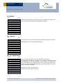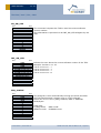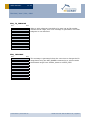
1
USER MANUAL V1.25 Transceiver Module TCM 300 / TCM 300C TCM 320 / TCM 320C June 14, 2011 Observe precautions! Electrostatic sensitive devices! Patent protected: WO98/36395, DE 100 25 561, DE 101 50 128, WO 2004/051591, DE 103 01 678 A1, DE 10309334, WO 04/109236, WO 05/096482, WO 02/095707, US 6,747,573, US 7,019,241 EnOcean GmbH Kolpingring 18a 82041 Oberhaching Germany Phone +49.89.67 34 689-0 Fax +49.89.67 34 689-50 [email protected] www.enocean.com Subject to modifications TCM 300 / 300C / 320 / 320C User Manual V1.25 June 14, 2011 4:53 PM Page 1/52 USER MANUAL V1.25 TCM 300 / 300C / 320 / 320C REVISION HISTORY The following major modifications and improvements have been made to the first version of this document: No 1.01 1.02 1.03 1.10 1.20 1.21 1.25 Major Changes Tape running direction added in 3.8 Dimension of TCM 320 corrected (width 18 mm instead of 19 mm) Editorial changes Timing information regarding serial protocol added in A.2, A.3. 0xFFFF_FFFF excluded from usable ID range, because this ID will be used as broadcast ID. Error corrected in 3.2.1. and 4.1: Maximum gain of external antenna at 50Ohm output RF_50 is 0dBi! Error corrected in 2.2: WXODIO is configured as output and provides information on VON signal Note added in 3.5 Remarks added regarding use of IOVDD in 2.2.; Antenna specification in 3.3.1 extended. Updated information on conducted output power in 1.2; A.2.2 changed to point to EnOcean Alliance Website; A.2.3 and A.2.4 removed; editorial changes Published by EnOcean GmbH, Kolpingring 18a, 82041 Oberhaching, Germany www.enocean.com, [email protected], phone +49 (89) 6734 6890 © EnOcean GmbH All Rights Reserved Important! This information describes the type of component and shall not be considered as assured characteristics. No responsibility is assumed for possible omissions or inaccuracies. Circuitry and specifications are subject to change without notice. For the latest product specifications, refer to the EnOcean website: http://www.enocean.com. As far as patents or other rights of third parties are concerned, liability is only assumed for modules, not for the described applications, processes and circuits. EnOcean does not assume responsibility for use of modules described and limits its liability to the replacement of modules determined to be defective due to workmanship. Devices or systems containing RF components must meet the essential requirements of the local legal authorities. The modules must not be used in any relation with equipment that supports, directly or indirectly, human health or life or with applications that can result in danger for people, animals or real value. Components of the modules are considered and should be disposed of as hazardous waste. Local government regulations are to be observed. Packing: Please use the recycling operators known to you. © 2010 EnOcean | www.enocean.com TCM 300 / 300C / 320 / 320C User Manual V1.25 | Page 2/52 USER MANUAL V1.25 TCM 300 / 300C / 320 / 320C TABLE OF CONTENT 1 1.1 1.2 1.3 1.4 1.5 GENERAL DESCRIPTION .................................................................................5 Basic functionality..........................................................................................5 Technical data ...............................................................................................5 Physical dimensions .......................................................................................6 Environmental conditions ................................................................................7 Ordering information ......................................................................................7 2 FUNCTIONAL DESCRIPTION ............................................................................8 2.1 Pin out .........................................................................................................8 2.2 Pin description and operational characteristics ...................................................9 2.2.1 GPIO supply voltage - IOVDD .................................................................... 11 2.3 Absolute maximum ratings (non operating) .................................................... 12 2.4 Maximum ratings (operating) ........................................................................ 12 2.5 Operating modes ......................................................................................... 13 2.6 Mode selection ............................................................................................ 14 2.7 Repeater configuration ................................................................................. 15 2.8 Teach-in procedure ...................................................................................... 16 2.8.1 Setting the receiver to learning mode ......................................................... 16 2.8.2 Confirmation of Learning Mode .................................................................. 16 2.8.3 Teaching in a transmitter .......................................................................... 16 2.8.4 Confirmation of correct learning/deletion .................................................... 17 2.8.5 Learning of further transmitters ................................................................. 17 2.8.6 Selecting the next channel ........................................................................ 17 2.8.7 Leaving learning mode ............................................................................. 17 2.8.8 Deleting a transmitter .............................................................................. 17 2.9 Remote management ................................................................................... 18 2.9.1 Remote Management Control Commands (RMCC) ........................................ 18 2.9.2 Remote Procedure Calls (RPC) ................................................................... 18 2.10 Smart Acknowledge ................................................................................ 19 2.11 Transmit timing ...................................................................................... 19 3 APPLICATIONS INFORMATION ....................................................................... 20 3.1 Transmission range ...................................................................................... 20 3.2 Antenna options TCM 300 / TCM 300C............................................................ 21 3.2.1 Overview ................................................................................................ 21 3.2.2 Whip antenna .......................................................................................... 22 3.2.3 Chip antenna........................................................................................... 23 3.2.4 Splatch antenna ...................................................................................... 25 3.2.5 Helical antenna........................................................................................ 26 3.3 Antenna options TCM 320 / 320C................................................................... 27 3.3.1 Mounting the whip antenna ....................................................................... 27 3.3.2 Mounting 50 Ω antennas ........................................................................... 28 3.4 Recommendations for laying a whip antenna ................................................... 29 3.5 Power supply requirements ........................................................................... 30 3.6 Layout recommendations .............................................................................. 30 3.6.1 TCM 300/300C recommended foot pattern .................................................. 31 3.7 Soldering information ................................................................................... 34 3.7.1 TCM 300 / TCM 300C ............................................................................... 34 3.7.2 TCM 320 / TCM 320C ............................................................................... 35 3.8 Tape & Reel specification TCM 300 / TCM 300C ............................................... 35 © 2010 EnOcean | www.enocean.com TCM 300 / 300C / 320 / 320C User Manual V1.25 | Page 3/52 USER MANUAL V1.25 TCM 300 / 300C / 320 / 320C 3.9 Backward compatibility to TCM 220C .............................................................. 36 3.10 Using RVDD ........................................................................................... 36 3.11 Voltage dips ........................................................................................... 36 4 AGENCY CERTIFICATIONS ............................................................................ 37 4.1 CE approval ................................................................................................ 37 4.2 FCC (United States) Certification ................................................................... 38 4.3 IC (Industry Canada) Certification ................................................................. 41 A Serial Interface ........................................................................................... 43 A.1 EnOcean serial protocol ................................................................................ 43 A.1.1 Message format (ESP2) ............................................................................ 43 A.1.2 Byte signals and bit order ......................................................................... 43 A.1.3 Description of serial data structure............................................................. 44 A.2 Radio transmission/reception commands ........................................................ 45 A.2.1 Detailed description of ORG, DATA_BYTE, and STATUS fields ........................ 45 A.3 Command telegrams and messages ............................................................... 46 A.3.1 ID Range commands ................................................................................ 46 A.3.2 Receiver sensitivity commands .................................................................. 46 A.3.3 Reset command ....................................................................................... 46 A.3.4 SW Version ............................................................................................. 46 A.3.5 Error messages ....................................................................................... 47 A.3.6 Command Encoding ................................................................................. 48 © 2010 EnOcean | www.enocean.com TCM 300 / 300C / 320 / 320C User Manual V1.25 | Page 4/52 USER MANUAL V1.25 TCM 300 / 300C / 320 / 320C 1 GENERAL DESCRIPTION 1.1 Basic functionality The transceiver modules TCM 300 / 300C and TCM 320 / 320C enable the realization of highly efficient RF repeaters and transceivers for the EnOcean 868 MHz and 315 MHz radio systems. The module provides several built-in operating modes. In addition repeater functionality (1 or 2 level) can be activated. Using the Dolphin API library it is possible to write custom software for the module. All module variants are in-system programmable. Built-in operating modes Unidirectional serial communication Bidirectional serial communication 1-channel relay mode 4-channel relay mode 1-channel dimming mode Product variants TCM 300/300C: SMD mountable module for use with external antenna (868/315 MHz) TCM 320/320C: Variant for vertical mounting with pin connector. Whip antenna. (868/315 MHz). TCM 320C is backward compatible to TCM 220C Features accessible via API: Integrated 16 MHz 8051 CPU with 32 KB FLASH and 2 kB SRAM Various power down and sleep modes TCM 300/300C down to 0.2 µA current consumption TCM 320/320C down to 1.4 mA current consumption Up to 14 configurable I/Os (TCM 300/300C) 10 bit ADC, 8 bit DAC 1.2 Technical data Antenna Frequency Pre-installed 8.6 cm/15 cm whip antenna (TCM 320/TCM 320C) External whip or 50 Ω antenna mountable (TCM 300/TCM 300C) 315.0 MHz (TCM 3X0C)/868.3 MHz (TCM 3X0) Radio Standard Data rate/Modulation type EnOcean 868 MHz/315 MHz 125 kbps/ASK Receiver Sensitivity (at 25°C) Conducted Output Power @50Ω min / typ /max Power Supply Current Consumption 1 TCM 300: TCM 300C: TCM 320: TCM 320C: 3.0 5.5 1.2 3.5 typ. –96 dBm1 (868 MHz) typ. -98 dBm1 (315 MHz) dBm / 5.7 dBm / 7.0 dBm dBm / 7.5 dBm / 9.5 dBm dBm / 3.1 dBm / 5.2 dBm dBm / 5.5 dBm / 7.5 dBm 2.6 V–3.3 V (TCM 320/320C), 2.6 V–4.5 V (TCM 300/300C) Receive mode: typ. 33 mA, max. 43 mA (RX) Transmit mode: typ. 24 mA, max. 33 mA (TX) @ 0.1% telegram error rate (based on 3 transmitted sub-telegrams) © 2010 EnOcean | www.enocean.com TCM 300 / 300C / 320 / 320C User Manual V1.25 | Page 5/52 USER MANUAL V1.25 TCM 300 / 300C / 320 / 320C Radio Regulations 1.3 R&TTE EN 300 220 (TCM 300/TCM 320) FCC CFR-47 Part 15 (TCM 300C/TCM 320C) Physical dimensions Unless otherwise specified dimensions are in mm. Tolerances: PCB outline dimensions ±0.2 mm All other tolerances ±0.1 mm TCM 300 / TCM 300C (pads on bottom side of PCB!) Unless otherwise specified dimensions are in mm. Tolerances: PCB outline dimensions ±0.2 mm All other tolerances ±0.1 mm TCM 320 / TCM 320C © 2010 EnOcean | www.enocean.com TCM 300 / 300C / 320 / 320C User Manual V1.25 | Page 6/52 USER MANUAL V1.25 TCM 300 / 300C / 320 / 320C PCB dimensions TCM 320/TCM 320C (without pin connector): 36.5 x 18 x 5.5 mm TCM 300/TCM 300C: 22 x 19 x 3.1 mm Pin connector 16 pins, grid 2.0 mm (4.0 mm in length, Weight 1.4 0.5 mm) TCM 320/320C: 3.7 g TCM 300/300C: 1.9 g Environmental conditions Operating temperature -25 °C … +85 °C Storage temperature -40 °C … +85 °C Storage temperature in tape & reel package Humidity 1.5 -20 °C … +50 °C 0% … 93% r.H., non-condensing Ordering information Type TCM 300 TCM 320 TCM 300C TCM 320C Ordering Code S3003-K300 S3003-K320 S3033-K300 S3033-K320 © 2010 EnOcean | www.enocean.com Frequency 868.3 MHz 868.3 MHz 315.0 MHz 315.0 MHz TCM 300 / 300C / 320 / 320C User Manual V1.25 | Page 7/52 USER MANUAL V1.25 TCM 300 / 300C / 320 / 320C 2 FUNCTIONAL DESCRIPTION 2.1 Pin out RF_WHIP XTAL 16MHz Antenna balun 1 VDD 26 DVDD VDD XTAL 16MHz n.c. GND IOVDD Antenna balun RSDADIO3 EO3000I RF_WHIP WSDADIO2 GND SCLKDIO1 SCSEDIO0 18 PROG_EN GND ADIO7 ADIO6 ADIO5 ADIO4 ADIO3 ADIO0 9 TCM300/300C TOP VIEW ADIO2 GND ADIO1 RF_50 RVDD GND GND RESET 16 PROG_EN RSDADIO3 RESET GND WSDADIO2 SCLKDIO1 WXIDIO ADIO 7 SCSEDIO0 WXODIO ADIO6 GND ADIO 3 ADIO4 n.c. ADIO2 n.c. ADI O1 ADIO0 GND n.c. TCM320/320C TOP VIEW 1 G ND EO3000I The figure above shows the pin out of the TCM 300 / TCM 320 hardware. The pins are named according to the naming of the EO3000I chip to simplify usage of the DOLPHIN API. The table in section 2.2 shows the translation of hardware pins to a naming that fits the functionality of the built-in firmware. When writing own firmware based on the DOLPHIN API please refer to the Dolphin Core Description and use this manual only for information regarding the module hardware, such as pin out, layout recommendations, power supply requirements, antenna options, and approvals. © 2010 EnOcean | www.enocean.com TCM 300 / 300C / 320 / 320C User Manual V1.25 | Page 8/52 USER MANUAL V1.25 TCM 300 / 300C / 320 / 320C 2.2 Pin description and operational characteristics HW Symbol Function Characteristics GND VDD Ground connection Supply voltage RVDD RF supply voltage regulator output Must be connected to GND; see 3.5 TCM 300/300C: 2.6 V – 4.5 V TCM 320/320C: 2.6 V – 3.3 V Max. ripple: see 2.4 1.8 V Output current: max. 100 µA with built-in firmware (RX on) max. 10 mA while not in RX/TX mode DVDD IOVDD RESET PROG_EN ADIO0 ADIO1 ADIO2 ADIO3 ADIO4 ADIO5 ADIO6 Digital supply voltage regulator output GPIO supply voltage 1.8 V Output current: max. 5 mA TCM 320/320C: internally connected to VDD TCM 300/300C: Must be connected to desired interface supply voltage (see 2.4) See also 2.2.1. Reset input Active high reset (1.8 V). External 10 kΩ pullProgramming I/F down required. Programming I/F HIGH: programming mode active LOW: operating mode Digital input, external 10 kΩ pull-down required. MODE_SEL Analog input: At start-up input voltage is measured and mode is selected. See chapter 2.6. MODE 0: not used In mode 0 the repeater level is 1 and cannot be modified. MODE 1-4: REP_LEVEL Mode 1-4: At start-up the repeater level is selected: Repeater level 1: LOW Repeater level 2: HIGH Digital input, internal pull-up active REPEATER At start-up the repeater can be switched on: Repeater on: LOW Repeater off: HIGH Digital input, internal pull-up active MODE 0: Sensitivity Low sensitivity: LOW High sensitivity: HIGH Digital input, internal pull-up active MODE 1-4: LRN Enter/leave teach-in mode. See chapter 2.8 Digital input, internal pull-up active MODE 0: not used Internal pull-up active MODE 1-4: CLR Clear ID memory. See chapter 2.8 Digital input, internal pull-up active Not used Digital output, internally set to LOW MODE 0-1: SER_RX UART input MODE 2-4: not used Digital input, internal pull-up active © 2010 EnOcean | www.enocean.com TCM 300 / 300C / 320 / 320C User Manual V1.25 | Page 9/52 USER MANUAL V1.25 TCM 300 / 300C / 320 / 320C ADIO7 SCSEDIO0 SCLKDIO1 WSDADIO2 RSDADIO3 MODE 0-1: SER_TX UART output Max. output current: 2 mA @ IOVDD=3.3 V 0.65 mA @ IOVDD=1.8 V MODE 2-3: CHANNEL0 Digital output channel 0 Max. output current: 2 mA @ IOVDD=3.3 V 0.65 mA @ IOVDD=1.8 V MODE 4: not used Digital output, internally set to LOW Programming I/F MODE 0, 2: not used Digital output, internally set to LOW MODE 1: LRN_TOGGLE Digital output Max. output current: 2 mA @ IOVDD=3.3 V 0.65 mA @ IOVDD=1.8 V MODE 3: CHANNEL1 Digital output channel 1 Max. output current: 2 mA @ IOVDD=3.3 V 0.65 mA @ IOVDD=1.8 V MODE 4: PWM Dimmer output, 50 kHz Programming I/F MODE 0-2: not used Digital output, internally set to LOW MODE 3: CHANNEL2 Digital output channel 2 Max. output current: 2 mA @ IOVDD=3.3 V 0.65 mA @ IOVDD=1.8 V MODE 4: PWM_IND Indicating if PWM is active. Digital output. Max. output current: 2 mA @ IOVDD=3.3 V 0.65 mA @ IOVDD=1.8 V Programming I/F MODE 0-2, 4: not used Digital output, internally set to LOW MODE 3: CHANNEL3 Digital output channel 3 Max. output current: 2 mA @ IOVDD=3.3 V 0.65 mA @ IOVDD=1.8 V Programming I/F MODE 0: RMI Normal operation: Digital output, internally set to LOW Remote Management: ACTION command indicator (see 2.9.1) Max. output current: 2 mA @ IOVDD=3.3 V 0.65 mA @ IOVDD=1.8 V MODE 1-4: LMI Normal operation: Learn mode indicator Remote Management: ACTION command indicator (see 2.9.1) Digital output © 2010 EnOcean | www.enocean.com TCM 300 / 300C / 320 / 320C User Manual V1.25 | Page 10/52 USER MANUAL V1.25 TCM 300 / 300C / 320 / 320C Max. output current: 2 mA @ IOVDD=3.3 V 0.65 mA @ IOVDD=1.8 V WXIDIO WXODIO Programming I/F Not used Not used RF_WHIP RF_50 n.c. RF output RF output Not connected Digital output, internally set to LOW Digital output, HIGH if VDD>VON, LOW if VDD<VON, see also 3.11 Output for whip antenna 50 Ohm output for external antenna Do not connect! 2.2.1 GPIO supply voltage - IOVDD For digital communication with other circuitry (peripherals) the digital I/O configured pins of the mixed signal sensor interface (ADIO0 to ADIO7) and the pins of the serial interface (SCSEDIO0, SCLKDIO1, WSDADIO2, RSDADIO3) may be operated from supply voltages different from DVDD. Therefore an interface voltage supply pin IOVDD is available which can be connected either to DVDD or to an external supply within the tolerated voltage range of IOVDD. If DVDD=0 V (e.g. in any sleepmode) and IOVDD is supplied, there may be unpredictable and varying current from IOVDD caused by internal floating nodes. It must be taken care that the current into IOVDD does not exceed 10 mA while DVDD=0 V. If DVDD=0 V and IOVDD is not supplied, do not apply voltage to any above mentioned pin. This may lead to unpredictable malfunction of the device. In TCM 320/TCM 320C VDD is internally connected to IOVDD! Therefore the above mentioned issues have to be considered when writing own firmware based on API. IOVDD voltage must not exceed VDD voltage! A malfunction of the module may be caused by such inverse supply! For I/O pins configured as analog pins the IOVDD voltage level is not relevant! However it is important to connect IOVDD to a supply voltage as specified in 2.4. © 2010 EnOcean | www.enocean.com TCM 300 / 300C / 320 / 320C User Manual V1.25 | Page 11/52 USER MANUAL V1.25 TCM 300 / 300C / 320 / 320C 2.3 Absolute maximum ratings (non operating) Symbol Parameter Min Supply voltage at VDD VDD TCM 300 -0.5 TCM 320 (limitation due to internal VDD-IOVDD connection) -0.5 IOVDD GPIO supply voltage -0.5 GND Ground connection 0 VINA Voltage at every analog input pin -0.5 Voltage at RESET, and every digital input pin except WXI-0.5 VIND1 DIO/WXODIO VIND2 Voltage at WXIDIO / WXODIO input pin -0.5 2.4 Max Units 5.5 3.6 3.6 0 2 3.6 V V V V V V 2 V Maximum ratings (operating) Symbol Parameter Supply voltage at VDD VDD TCM 300 TCM 320 Min 2.6 2.6 1.7 IOVDD GPIO supply voltage (see also 2.2.1) GND VINA Ground connection Voltage at every analog input pin Voltage at RESET, and every digital input pin except WXIDIO / WXODIO Voltage at WXIDIO / WXODIO input pin Max. ripple at VDD VIND1 VIND2 VDDR © 2010 EnOcean | www.enocean.com 0 0 0 0 Max Units 4.5 3.3 MIN (3.6; VDD) 0 2.0 3.6 V V V 2.0 50 V mVpp V V V TCM 300 / 300C / 320 / 320C User Manual V1.25 | Page 12/52 USER MANUAL V1.25 TCM 300 / 300C / 320 / 320C 2.5 Operating modes Mode Function 0 Unidirectional serial interface compatible with TCM 220C, no teach-in capability 1 Bidirectional serial interface, teach-in capability for up to 30 entries2 2 Rocker Switch - 1 channel, teach-in capability for up to 30 entries2 Rocker Switch - 4 channels, teach-in capability for up to 30 entries3 Dimming - 1 channel, teach-in capability for up to 30 entries2 3 4 5 Output signal description SER_TX: UART output, supplies standard data blocks of information from all received EnOcean radio telegrams (9600 bps; 8 data bits, no parity bit, one start bit, one stop bit). For further information see chapter A.1 SER_RX, SER_TX: Asynchronous bidirectional Interface, supplies standard data blocks of information from all received EnOcean radio telegrams (9600 bps; 8 data bits, no parity bit, one start bit, one stop bit). For further information see chapter A.1 LRN_TOGGLE: Learning mode status indicator Supplies the desired logic switching state “on/off” at CHANNEL0 when pushing the switch rockers No. of channels 1 Same as Mode 2 but operation of 4 receiver channels (CHANNEL0, CHANNEL1, CHANNEL2, CHANNEL3) 4 PWM is the PWM output 1 I-button pressed for shorter than 0.5 s: ON (Restore duty cycle stored before last switch-off). O-button pressed for shorter than 0.5 s: OFF O-/I-button pressed longer than 0.5 s: Duty cycle variation from 10% up to 100% (O=less, I=more; ~300 PWM steps, increment every 15 ms). Duty cycle variation stops when button is released. PWM_IND is active as long as duty cycle is not 0% Reserved 2 Each rocker of a PTM transmitter is counted as 1 entry Each rocker is counted as 1 entry. If the same rocker is teached into several channels, 1 entry per channel is needed. 3 © 2010 EnOcean | www.enocean.com TCM 300 / 300C / 320 / 320C User Manual V1.25 | Page 13/52 USER MANUAL V1.25 TCM 300 / 300C / 320 / 320C 2.6 Mode selection The operating mode is defined at start-up of the module via a measurement of the voltage at ADIO0. As long as IDs are stored in ID memory, the operating mode can only be changed after deleting all IDs from memory, e.g. via CLR! Mode ADIO0 (MODE_SEL) input voltage range 0 0% to 3.99% VDD 1 2 4% to 11.99% VDD 12% to 19.99% VDD 3 20% to 27.99% VDD 4 28% to 35.99% VDD 5 36% to 39.99% VDD © 2010 EnOcean | www.enocean.com Proposed component values R1: 0 Ohm R2: leave open R3: leave open C1: leave open R1: 1k2 ±1% R2: 15k ±1% R3: 150k ±1% C1: 100p R1: 2k2 ±1% R2: 12k ±1% R3: 270k ±1% C1: 100p R1: 3k9 ±1% R2: 15k ±1% R3: 68k ±1% C1: 100p R1: 4k7 ±1% R2: 12k ±1% R3: 56k ±1% C1: 100p R1: 5k6 ±1% R2: 10k ±1% R3: 56k ±1% C1: 100p VDD R2 R3 ADIO0 R1 C1 GND TCM 300 / 300C / 320 / 320C User Manual V1.25 | Page 14/52 USER MANUAL V1.25 TCM 300 / 300C / 320 / 320C 2.7 Repeater configuration TCM 3x0 provides the option to activate a one or two-level repeater for EnOcean radio telegrams. 1-level repeater: If a received telegram is a valid and original (not yet repeated), the telegram is repeated after a random delay. 2-level repeater: If a received telegram is valid and original or repeated once, the telegram is repeated after a random delay. 2-level repeating function should only be activated if really needed! Otherwise the system function can be compromised by collisions of telegrams. The repeated telegram is marked as “repeated” by an increased repeater counter. Setting the repeater level: At start-up of the module repeater on/off and repeater level are determined. Please refer to the table in 2.2 regarding the configuration options. Please note that in Mode 0 2-level repeating is not possible (for backward compatibility to TCM 220C)! The figure below shows an example circuit for a repeater. © 2010 EnOcean | www.enocean.com TCM 300 / 300C / 320 / 320C User Manual V1.25 | Page 15/52 USER MANUAL V1.25 TCM 300 / 300C / 320 / 320C 2.8 Teach-in procedure Modes 1 to 4 support teach-in of transmitters. Please make sure not to remove supply voltage while in LRN mode! The flash content could get corrupted! 2.8.1 Setting the receiver to learning mode Via CLR Pin (ADIO4): Contact to GND longer than t = 2 seconds. Learning Mode LRN is entered after clearing ID memory. Via LRN Pin (ADIO3): Contact to GND longer than t = 0.5 seconds. In multi-channel receiver mode, the pin has to be contacted several times until the desired channel number is selected (the number of channels is given by the selected operating mode). Via Remote Config Control: Please refer to documentation of remote management. 2.8.2 Confirmation of Learning Mode Mode 0 1 2 3 4 5 Confirmation No Learn capability LMI HIGH continuously, LMI HIGH continuously, LMI HIGH continuously, LMI HIGH continuously, 10% and 100% Reserved for future use LRN_TOGGLE toggling every 1 s. CHANNEL0 toggling every 1 s. current CHANNELx toggling every 1 s. DIM IND HIGH, and PWM toggling every 1 s between 2.8.3 Teaching in a transmitter In learning mode LRN, the sensitivity of the module is limited to in-room operations and learning of repeater powered signals is disabled (to avoid unintentional learning). Therefore ensure that the associated radio transmitter will be in a distance less than 5 m to the receiver (not necessary within Remote Learn Mode). Trigger the telegram of the associated radio transmitter within 30 seconds: Operate the switch radio transmitter (RPS or HRC) at least once (press I-button or O- button of the rocker that is to be assigned to the selected receiver channel). If the same rocker is operated again within 4 seconds it will still be learned. If the same rocker is operated again after more than 4 seconds it will be deleted again. Please note that teach-in without rocker information is not possible” Please note that scene switches (HRC and last 3 ID bits 0B111) cannot be teach-in! Or activate the sensor radio transmitter (1BS, 4BS) least once with active LRN bit (DI_3=0, please refer to “Standardization EnOcean Communication Profiles”). If the same transmitter is operated again after more than 4 seconds with active LRN bit it will be deleted again. © 2010 EnOcean | www.enocean.com TCM 300 / 300C / 320 / 320C User Manual V1.25 | Page 16/52 USER MANUAL V1.25 TCM 300 / 300C / 320 / 320C Please note that in modes 2, 3, and 4 only RPS or HRC telegrams can be learned! 2.8.4 Confirmation of correct learning/deletion The output which is toggling every second while in teach-in mode (see above) will stay switched high for 4 seconds to signal that a transmitter has been learned. In case a transmitter ID has been deleted it will stay 4 seconds low. 2.8.5 Learning of further transmitters After confirmation, the receiver changes again to readiness for learning. Further transmitters can be learned immediately. If available the next receiver channel can be entered by connecting the LRN pin to GND longer than t = 0.5 seconds. A maximum of 30 radio transmitters can be learned (further attempts will be ignored; instead of learning confirmation, operating mode is entered). Each rocker of a radio transmitter is counted as one transmitter. 2.8.6 Selecting the next channel By fresh contacting of the LRN pin to GND the next remaining channel is selected. In onechannel mode or after the last channel, the operating mode is entered again. 2.8.7 Leaving learning mode LRN mode is left in either one of the following events: Output of last available channel is toggling and a fresh contacting of the LRN pin to GND for 0.5 seconds is performed No ID has been added/deleted during the last 30 seconds. Memory was full and another ID was sent to be learnt 2.8.8 Deleting a transmitter Deletion of one specific transmitter: Use the same procedure as learning the associated transmitter. As transmitter delete confirmation, the corresponding function outputs remain in inactive state for 4 seconds while LMI keeps active. After that, a wrongly deleted transmitter can be learned again immediately. In order to delete a PTM transmitter the same rocker as during learn has to be operated. If several rockers of a PTM transmitter have been learned, all have to be deleted separately. Deletion of all learned transmitters: Connect the CLR pin longer than 2 seconds to GND All learned transmitters on all channels are deleted at the same time. After this, the receiver enters Learning Mode. © 2010 EnOcean | www.enocean.com TCM 300 / 300C / 320 / 320C User Manual V1.25 | Page 17/52 USER MANUAL V1.25 TCM 300 / 300C / 320 / 320C 2.9 Remote management TCM 300 supports the remote management specification which is available from EnOcean upon request. This allows controlling the teach-in procedure via a Remote Config Control device. 2.9.1 Remote Management Control Commands (RMCC) All RMCCs supported. Mode 0 1 2 3 4 5 Reaction to ACTION COMMAND (Function code 0x005) RMI HIGH for 1 s. LMI HIGH, and LRN_TOGGLE on for 1 s. LMI HIGH, and CHANNEL0 invert for 1 s. LMI HIGH, and all CHANNELx inverted for 1 s. LMI HIGH, DIM IND inverted, and PWM inverted for 1 s. Reserved for future use 2.9.2 Remote Procedure Calls (RPC) Supported RPCs: Remote learn command, function code 0x201 Smart ACK: Read mailbox settings, function code 0x205, settings type 0x01 Smart ACK: Delete mailbox, function code 0x206, operation type 0x02 REMOTE LEARN COMMAND: EEP: 0x000000 Mode 0 1 2 3 4 5 Flag in command n.a. 0x01 0x03 0x01 0x03 0x01 0x02 0x03 0x01 0x03 n.a. Reaction No reaction, no Learn Mode available Start Remote Learn Mode Stop Remote Learn Mode Start Remote Learn Mode Stop Remote Learn Mode Start Remote Learn Mode Next channel Stop Remote Learn Mode Start Remote Learn Mode Stop Remote Learn Mode No reaction, reserved for future use The signalling is the same as described above in 2.8. Differences between remote learn mode and normal learn mode: In remote learn mode also repeated telegrams will be accepted 3 transmissions within 2 seconds are required, instead of 1 transmission For detailed information on remote management please refer to the Remote Management system specification. © 2010 EnOcean | www.enocean.com TCM 300 / 300C / 320 / 320C User Manual V1.25 | Page 18/52 USER MANUAL V1.25 TCM 300 / 300C / 320 / 320C 2.10 Smart Acknowledge TCM 3x0 provides a post master function with 15 mail boxes for systems using EnOcean smart acknowledge technology. This functionality is switched on in all operating modes. For detailed information on smart acknowledge please refer to the Smart Acknowledge system specification. When teaching-in a device using Smart Acknowledge please take care to switch off all TCM 3xy devices which are not continuously powered. Otherwise these TCM 3xy modules could be declared postmaster. As soon as the power supply is switched off a postmaster would be missing and Smart Acknowledge would not work any longer! 2.11 Transmit timing The setup of the transmission timing allows avoiding possible of other EnOcean transmitters as well as disturbances from transmission cycle, 3 identical subtelegrams are transmitted sion of a subtelegram lasts approximately 1.2 ms. The delay sion bursts is affected at random. © 2010 EnOcean | www.enocean.com collisions with data packages the environment. With each within 40 ms. The transmisbetween the three transmis- TCM 300 / 300C / 320 / 320C User Manual V1.25 | Page 19/52 USER MANUAL V1.25 TCM 300 / 300C / 320 / 320C 3 APPLICATIONS INFORMATION 3.1 Transmission range The main factors that influence the system transmission range are type and location of the antennas of the receiver and the transmitter, type of terrain and degree of obstruction of the link path, sources of interference affecting the receiver, and “dead” spots caused by signal reflections from nearby conductive objects. Since the expected transmission range strongly depends on this system conditions, range tests should categorically be performed before notification of a particular range that will be attainable by a certain application. The following figures for expected transmission range are considered by using a PTM, a STM or a TCM radio transmitter device and the TCM radio receiver device with preinstalled whip antenna and may be used as a rough guide only: Line-of-sight connections: Typically 30 m range in corridors, up to 100 m in halls Plasterboard walls / dry wood: Typically 30 m range, through max. 5 walls Line-of-sight connections: Typically 30 m range in corridors, up to 100 m in halls Ferro concrete walls / ceilings: Typically 10 m range, through max. 1 ceiling Fire-safety walls, elevator shafts, staircases and supply areas should be considered as screening. The angle at which the transmitted signal hits the wall is very important. The effective wall thickness – and with it the signal attenuation – varies according to this angle. Signals should be transmitted as directly as possible through the wall. Wall niches should be avoided. Other factors restricting transmission range: Switch mounted on metal surfaces (up to 30% loss of transmission range) Hollow lightweight walls filled with insulating wool on metal foil False ceilings with panels of metal or carbon fibre Lead glass or glass with metal coating, steel furniture The distance between EnOcean receivers and other transmitting devices such as computers, audio and video equipment that also emit high-frequency signals should be at least 0.5 m A summarized application note to determine the transmission range within buildings is available as download from www.enocean.com. © 2010 EnOcean | www.enocean.com TCM 300 / 300C / 320 / 320C User Manual V1.25 | Page 20/52 USER MANUAL V1.25 TCM 300 / 300C / 320 / 320C 3.2 Antenna options TCM 300 / TCM 300C 3.2.1 Overview Several antenna types have been investigated by EnOcean. They all have advantages and disadvantages as shown in the following table. Advantages Disadvantages Whip Antenna (15 cm @ 315 MHz, 8.6 cm @ 868 MHz) Cheap Automatic placement difficult Omnidirectional Bending influences performance Large size Chip Antenna (AMD1103-ST01 @ 315 MHz/868 MHz) Omnidirectional Expensive Very sensitive to environment (GND plane, Small size components), minimum distance space to other components needed Automatic placement possible Splatch Antenna (ANT-315-SP1 @ 315 MHz, ANT-868-SP1 @ 868 MHz) Omnidirectional Expensive Not very sensitive to environment, low distance space to other components reLarge size quired Automatic placement possible Helical Antenna (ANT-315-HE @ 315 MHz) Large distance space to other components Omnidirectional required Cheap Large size (3D) 868 MHz modules used in Europe do not need additional approval if the external antenna fulfils the following requirements: Antenna type Passive Mandatory for radio approval Frequency band 868 MHz ISM Antenna must be suited for this band Impedance ~50 Ohm Mandatory for radio approval Maximum gain ≤ 0 dBi Mandatory for radio approval VSWR ≤ 1.5:1 Important for compatibility with EnOcean protocol Return Loss > 14 dB Important for compatibility with EnOcean protocol Bandwidth ≤ 20 MHz Important if 10 V/m EMI robustness required for device For 315 MHz modules (STM 300C and TCM 3X0C) please note that a full approval is needed if modules are used with antennas other than the specified whip antenna. © 2010 EnOcean | www.enocean.com TCM 300 / 300C / 320 / 320C User Manual V1.25 | Page 21/52 USER MANUAL V1.25 TCM 300 / 300C / 320 / 320C 3.2.2 Whip antenna 315 MHz Antenna: 150 mm wire, connect to RF_WHIP Minimum GND plane: 50 mm x 50 mm Minimum distance space: 10 mm 868 MHz Antenna: 86 mm wire, connect to RF_WHIP Minimum GND plane: 38 mm x 18 mm Minimum distance space: 10 mm Specification of the whip antenna; L=150 mm @ 315 MHz, L=86 mm @ 868 MHz © 2010 EnOcean | www.enocean.com TCM 300 / 300C / 320 / 320C User Manual V1.25 | Page 22/52 USER MANUAL V1.25 TCM 300 / 300C / 320 / 320C 3.2.3 Chip antenna 315 MHz Antenna: AMD1103-ST01 Manufacturer: Mitsubishi Matching circuit: L1=47 nH L2=390 nH L3 optional for additional optimization Minimum distance space and layout: Distance space for components 15 15 11 L2 L1 15 AMD1103-ST01 GND plane L3 50 RF_50 35 50 Minimum distance space above and below PCB: 11 mm © 2010 EnOcean | www.enocean.com TCM 300 / 300C / 320 / 320C User Manual V1.25 | Page 23/52 USER MANUAL V1.25 TCM 300 / 300C / 320 / 320C 868 MHz Antenna: AMD1103-ST01 Manufacturer: Mitsubishi Matching circuit: L1=6.8 nH L2=39 nH L3=8.2 nH Minimum distance space, PCB properties and layout: PCB Material: FR4, tCu=35 µm, hPCB=1.5 mm, RF_50 micro strip width = 2.7 mm, if these parameters can not be hold, then new matching values are required. Distance space for components 11 20 15 L2 L1 5 11 17 AMD1103-ST01 L3 GND plane RF_50 50 34 50 Minimum distance space above and below PCB: 11 mm © 2010 EnOcean | www.enocean.com TCM 300 / 300C / 320 / 320C User Manual V1.25 | Page 24/52 USER MANUAL V1.25 TCM 300 / 300C / 320 / 320C 3.2.4 Splatch antenna 315/868 MHz Antenna: ANT-315-SP Manufacturer: Linx Technologies / Antenna Factor Matching circuit: Not needed Minimum distance space, PCB properties and layout: PCB Material: FR4, tCu=35 µm, hPCB=1.5 mm, RF_50 micro strip width = 2.7 mm if these parameters can not be hold, then additional matching is required see chapter 3.5.3. 4 Distance space for components 4 4 4 RF_50 GND 45 35 38 Minimum distance space above and below PCB: 12 mm © 2010 EnOcean | www.enocean.com TCM 300 / 300C / 320 / 320C User Manual V1.25 | Page 25/52 USER MANUAL V1.25 TCM 300 / 300C / 320 / 320C 3.2.5 Helical antenna 315 MHz Antenna: ANT-315-HE Manufacturer: Linx Technologies / Antenna Factor Matching circuit: L1=5,1 nH L2=18 nH Minimum distance space and layout: Distance space for components 21 21 5 10 L2 L1 21 RF_50 ANT-315-HE 45 GND plane 20 55 Minimum distance above and below axis of antenna: 21 mm © 2010 EnOcean | www.enocean.com TCM 300 / 300C / 320 / 320C User Manual V1.25 | Page 26/52 USER MANUAL V1.25 TCM 300 / 300C / 320 / 320C 3.3 Antenna options TCM 320 / 320C Positioning and choice of receiver and transmitter antennas are the most important factors in determining system transmission range. 3.3.1 Mounting the whip antenna For good receiver performance, great care must be taken about the space immediately around the antenna since this has a strong influence on screening and detuning the antenna. The antenna should be drawn out as far as possible and must never be cut off. Mainly the far end of the wire should be mounted as far away as possible (at least 15 mm) from all metal parts, ground planes, PCB strip lines and fast logic components (e.g. microprocessors). Do not roll up or twist the whip antenna! Radio frequency hash from the motherboard desensitizes the receiver. Therefore: PCB strip lines on the user board should be designed as short as possible A PCB ground plane layer with sufficient ground vias is strongly recommended See also section 3.5 for power supply requirements. Problems may especially occur with switching power supplies! Specification of the TCM whip antenna: L=150 mm @ 315 MHz, L=86 mm @ 868 MHz AWG24 wire composed of 7 strands of AWG32 wire Material is PVC according to DIN VDE 0207 Self-extinguishing and flame retardant according to EN 50265-2-1 / IEC 60332-1 Isolation material may brake at temperatures below -15 °C. Please take care to fix the antenna cable in case vibrations are expected. © 2010 EnOcean | www.enocean.com TCM 300 / 300C / 320 / 320C User Manual V1.25 | Page 27/52 USER MANUAL V1.25 TCM 300 / 300C / 320 / 320C 3.3.2 Mounting 50 Ω antennas For mounting the receiver at bad RF locations (e.g. within a metal cabinet), an external 50 Ω antenna may be connected. The whip antenna must be removed in this case! TCM 320 provides soldering pads for an SMA connector, e.g. from Tyco Electronics: X remove GND TCM320C: X remove 50Ω GND GND GND Modification procedure: TCM 320: Remove whip antenna and mount SMA connector TCM 320C: Remove whip antenna and 12 pF capacitor (see figure above). Then mount SMA connector For 315 MHz modules (TCM 300C and TCM 320C) please note that a full approval is needed if modules are used with external antennas other than the pre-installed whip antenna. When using the SMA connector pads please make sure no mechanical forces are exerted on the 16-pin connector! It is recommended to use a strain relief for that purpose. © 2010 EnOcean | www.enocean.com TCM 300 / 300C / 320 / 320C User Manual V1.25 | Page 28/52 USER MANUAL V1.25 TCM 300 / 300C / 320 / 320C 3.4 Recommendations for laying a whip antenna 9 PCB with GND PCB without GND Antenna too close to GND area 9 9 Antenna end led back to foot point Antenna too close to GND area 9 © 2010 EnOcean | www.enocean.com TCM 300 / 300C / 320 / 320C User Manual V1.25 | Page 29/52 USER MANUAL V1.25 TCM 300 / 300C / 320 / 320C 3.5 Power supply requirements In order to provide a good radio performance, great attention must be paid to the power supply and a correct layout and shielding. It is recommended to place a 22 µF ceramic capacitor between VDD and GND close to the module (material: X5R, X7R, min 6.3 V to avoid derating effects). In addition a 470 nH coil shall be inserted (Murata LQW18A, 0603) in the power supply line. For best performance it is recommended to keep the ripple on the power supply rail below 10 mVpp (see 2.4). All GND pins must be connected to GND. Be careful not to create loops! The ground must be realized ideally on both sides of the PCB board with many vias. At least there must be a short star connection. Otherwise RF performance can be reduced! 3.6 Layout recommendations The length of lines connected to I/Os should not exceed 5 cm. It is recommended to have a complete GND layer, at least below the module and directly connected components. GND must however be avoided 0…0.3mm below the PCB in the area marked by the circle in the figures below. The RVDD line should be kept as short as possible. Please consider recommendations in section 3.10. © 2010 EnOcean | www.enocean.com TCM 300 / 300C / 320 / 320C User Manual V1.25 | Page 30/52 USER MANUAL V1.25 TCM 300 / 300C / 320 / 320C 3.6.1 TCM 300/300C recommended foot pattern Top layer © 2010 EnOcean | www.enocean.com TCM 300 / 300C / 320 / 320C User Manual V1.25 | Page 31/52 USER MANUAL V1.25 TCM 300 / 300C / 320 / 320C Solder resist top layer © 2010 EnOcean | www.enocean.com TCM 300 / 300C / 320 / 320C User Manual V1.25 | Page 32/52 USER MANUAL V1.25 TCM 300 / 300C / 320 / 320C Solder paste top layer The data above is also available as EAGLE library. In order to ensure good solder quality a solder mask thickness of 150 µm is recommended. In case a 120 µm solder mask is used, it is recommended to enlarge the solder print. The pads on the solder print should then be 0.1 mm larger than the pad dimensions of the module as specified in chapter 1.3. (not relative to the above drawing). Nevertheless an application and production specific test regarding the amount of soldering paste should be performed to find optimum parameters. © 2010 EnOcean | www.enocean.com TCM 300 / 300C / 320 / 320C User Manual V1.25 | Page 33/52 USER MANUAL V1.25 TCM 300 / 300C / 320 / 320C 3.7 Soldering information 3.7.1 TCM 300 / TCM 300C TCM 300 has to be soldered according to IPC/JEDEC J-STD-020C standard. TCM 300 shall be handled according to Moisture Sensitivity Level MSL4 which means a floor time of 72 h. TCM 300 may be soldered only once, since one time is already consumed at production of the module itself. Once the dry pack bag is opened, the desired quantity of units should be removed and the bag resealed within two hours. If the bag is left open longer than 30 minutes the desiccant should be replaced with dry desiccant. If devices have exceeded the specified floor life time of 72 h, they may be baked according IPC/JEDEC J-STD-033B at max. 90°C for less than 60 h. Devices packaged in moisture-proof packaging should be stored in ambient conditions not exceeding temperatures of 40 °C or humidity levels of 90% r.H. TCM 300 modules have to be soldered within 6 months after delivery! © 2010 EnOcean | www.enocean.com TCM 300 / 300C / 320 / 320C User Manual V1.25 | Page 34/52 USER MANUAL V1.25 TCM 300 / 300C / 320 / 320C 3.7.2 TCM 320 / TCM 320C The EO3000I chip inside the module is a moisture sensitive device. In case of wave soldering the modules should be baked in advance. 3.8 Tape & Reel specification TCM 300 / TCM 300C Tape running direction © 2010 EnOcean | www.enocean.com TCM 300 / 300C / 320 / 320C User Manual V1.25 | Page 35/52 USER MANUAL V1.25 TCM 300 / 300C / 320 / 320C 3.9 Backward compatibility to TCM 220C In Mode 0 TCM 320C is backward compatible to its predecessor TCM 220C. There are a few minor restrictions of compatibility which are listed here: Parameter Maximum current consumption Maximum output current of outputs Thickness of module Maximum voltage rating at pin7 (TCM 320C: ADIO6; TCM 220C: IN_5) Minimum HIGH voltage level at input pins Post master function for systems with smart acknowledge Pull-down 10 kΩ required at Pin 13, 14 3.10 TCM 220C 34 mA 25 mA TCM 320C 1.55 V 2.0 V No Yes, 15 mail boxes No Yes 43 mA 2 mA (external driver transistor may be needed) 4.6 mm 5.5 mm 6V 3.6 V Using RVDD If RVDD is used in an application circuit a serial ferrite bead shall be used and wire length should be as short as possible (<3 cm). The following ferrite beads have been tested: 74279266 (0603), 74279205 (0805) from Würth. During radio transmission and reception only small currents may be drawn (I<100 µA). Pulsed current drawn from RVDD has to be avoided. If pulsed currents are necessary, sufficient blocking has to be provided. 3.11 Voltage dips The moduls are supporting the handling of supply voltage dips (as requested e.g. by EN60669-2-1). As soon as the supply voltage drops below the VON4 threshold level the current consumption is reduced. TCM 300 will enter standby sleep mode (worst case 35 µA), TCM 320 will enter short term sleep mode (1.8 mA) for 200 ms. As long as the voltage at VDD does not drop below VOFF during that phase the module will restore the output state as set before the voltage dip. The minimal difference between VON and VOFF is 0.35 V. The electric charge needed to bridge this interval is: 1.8 mA x 200 ms = 360 µC for TCM 320 0.035 mA x 200 ms = 7 µC for TCM 300 This electric charge can be stored in an external capacitor. The required capacity (do not forget to add component specific tolerances and some extra margin) calculates as: 360 µC / 0.35 V = 1028 µF for TCM 320 7 µC / 0.35 V = 20 µF for TCM 300 4 For a detailed definition of VON and VOFF please refer to „Dolphin Core Description“. © 2010 EnOcean | www.enocean.com TCM 300 / 300C / 320 / 320C User Manual V1.25 | Page 36/52 USER MANUAL V1.25 TCM 300 / 300C / 320 / 320C If other external circuitry has to be supplied the calculations have to be done accordingly, using the total current consumption of module and external circuitry. 4 AGENCY CERTIFICATIONS The modules have been tested to fulfil the approval requirements for CE (TCM 3x0) and FCC/IC (TCM 3x0C) based on the built-in firmware. When developing customer specific firmware based on the API for this module, special care must be taken not to exceed the specified regulatory limits, e.g. the duty cycle limitations! 4.1 CE approval The modules bear the EC conformity marking CE and conform to the R&TTE EU-directive on radio equipment. The assembly conforms to the European and national requirements of electromagnetic compatibility. The conformity has been proven and the according documentation has been deposited at EnOcean. The modules can be operated without notification and free of charge in the area of the European Union, and in Switzerland. The following provisos apply: • • • • • EnOcean RF modules must not be modified or used outside their specification limits. EnOcean RF modules may only be used to transfer digital or digitized data. Analog speech and/or music are not permitted. The final product incorporating EnOcean RF modules must itself meet the essential requirement of the R&TTE Directive and a CE marking must be affixed on the final product and on the sales packaging each. Operating instructions containing a Declaration of Conformity has to be attached. If the transmitter is used according to the regulations of the 868.3 MHz band, a so-called “Duty Cycle” of 1% per hour must not be exceeded. Permanent transmitters such as radio earphones are not allowed. The module must be used with only the following approved antenna(s). Type Parameter Value Wire/Monopole at RF_WHIP Maximum gain 1.0 dBi External antenna at RF_50 Antenna type Passive Impedance ~50 Ohm Maximum gain ≤ 0 dBi © 2010 EnOcean | www.enocean.com TCM 300 / 300C / 320 / 320C User Manual V1.25 | Page 37/52 USER MANUAL V1.25 TCM 300 / 300C / 320 / 320C 4.2 FCC (United States) Certification TCM 300C and TCM 320C LIMITED MODULAR APPROVAL This is an RF module approved for Limited Modular use operating as an intentional transmitting device with respect to 47 CFR 15.231(a-c) and is limited to OEM installation. The module is optimized to operate using small amounts of energy, and may be powered by a battery. The module transmits short radio packets comprised of control signals, (in some cases the control signal may be accompanied with data) such as those used with alarm systems, door openers, remote switches, and the like. The module does not support continuous streaming of voice, video, or any other forms of streaming data; it sends only short packets containing control signals and possibly data. The module is designed to comply with, has been tested according to 15.231(a-c), and has been found to comply with each requirement. Thus, a finished device containing the TCM 300C/TCM 320C radio module can be operated in the United States without additional Part 15 FCC approval (approval(s) for unintentional radiators may be required for the OEM’s finished product), under EnOcean’s FCC ID number. This greatly simplifies and shortens the design cycle and development costs for OEM integrators. The module can be triggered manually or automatically, which cases are described below. Manual Activation The radio module can be configured to transmit a short packetized control signal if triggered manually. The module can be triggered, by pressing a switch, for example. The packet contains one (or more) control signals that is(are) intended to control something at the receiving end. The packet may also contain data. Depending on how much energy is available from the energy source, subsequent manual triggers can initiate the transmission of additional control signals. This may be necessary if prior packet(s) was(were) lost to fading or interference. Subsequent triggers can also be initiated as a precaution if any doubt exists that the first packet didn’t arrive at the receiver. Each packet that is transmitted, regardless of whether it was the first one or a subsequent one, will only be transmitted if enough energy is available from the energy source. Automatic Activation The radio module also can be configured to transmit a short packetized control signal if triggered automatically, by a relevant change of its inputs or in response to receiving a signal from another transmitter, for example. Again, the packet contains a control signal that is intended to control something at the receiving end and may also contain data. As above, it is possible for the packet to get lost and never reach the receiver. However, if enough energy is available from the energy source, and the module has been configured to do so, then another packet or packets containing the control signal may be transmitted at a later time. The device is capable to operate as a repeater, which can receive signals from the following list of FCC/IC approved transmitters, and retransmit the signals. PTM 200C STM 110C TCM 200C TCM 220C TCM 300C STM 300C TCM 320C © 2010 EnOcean | www.enocean.com FCC FCC FCC FCC FCC FCC FCC ID:SZV-PTM200C ID:SZV-STM110C ID:SZV-TCM2XXC ID:SZV-TCM2XXC ID:SZV-STM300C ID:SZV-STM300C ID:SZV-TCM320C IC:5713A-PTM200C IC:5713A-STM110C IC:5713A-TCM2XXC IC:5713A-TCM2XXC IC:5713A-STM300C IC:5713A-STM300C IC:5713A-TCM320C TCM 300 / 300C / 320 / 320C User Manual V1.25 | Page 38/52 USER MANUAL V1.25 TCM 300 / 300C / 320 / 320C OEM Requirements In order to use EnOcean’s FCC ID number, the OEM must ensure that the following conditions are met: End users of products, which contain the module, must not have the ability to alter the firmware that governs the operation of the module. The agency grant is valid only when the module is incorporated into a final product by OEM integrators. The end-user must not be provided with instructions to remove, adjust or install the module. The Original Equipment Manufacturer (OEM) must ensure that FCC labeling requirements are met. This includes a clearly visible label on the outside of the final product. Attaching a label to a removable portion of the final product, such as a battery cover, is not permitted. The label must include the following text: TCM 300C: Contains FCC ID: SZV-STM300C The enclosed device complies with Part 15 of the FCC Rules. Operation is subject to the following two conditions: (i.) this device may not cause harmful interference and (ii.) this device must accept any interference received, including interference that may cause undesired operation. TCM 320C: Contains FCC ID: SZV-TCM320C The enclosed device complies with Part 15 of the FCC Rules. Operation is subject to the following two conditions: (i.) this device may not cause harmful interference and (ii.) this device must accept any interference received, including interference that may cause undesired operation. When the device is so small or for such use that it is not practicable to place the statement above on it, the information required by this paragraph shall be placed in a prominent location in the instruction manual or pamphlet supplied to the user or, alternatively, shall be placed on the container in which the device is marketed. However, the FCC identifier or the unique identifier, as appropriate, must be displayed on the device. The user manual for the end product must also contain the text given above. Changes or modifications not expressly approved by EnOcean could void the user's authority to operate the equipment. The module must be used with only the following approved antenna(s). Part Number N.A. © 2010 EnOcean | www.enocean.com Type Wire/Monopole Gain 1.0 dBi TCM 300 / 300C / 320 / 320C User Manual V1.25 | Page 39/52 USER MANUAL V1.25 TCM 300 / 300C / 320 / 320C The OEM must ensure that timing requirements according to 47 CFR 15.231(a-c) are met. The OEM must sign the OEM Limited Modular Approval Agreement with EnOcean © 2010 EnOcean | www.enocean.com TCM 300 / 300C / 320 / 320C User Manual V1.25 | Page 40/52 USER MANUAL V1.25 TCM 300 / 300C / 320 / 320C 4.3 IC (Industry Canada) Certification In order to use EnOcean’s IC number, the OEM must ensure that the following conditions are met: Labeling requirements for Industry Canada are similar to those required by the FCC. The Original Equipment Manufacturer (OEM) must ensure that IC labeling requirements are met. A clearly visible label on the outside of a non-removable part of the final product must include the following text: TCM 300C: Contains IC: 5713A-STM300C TCM 320C: Contains IC: 5713A-TCM320C The OEM must sign the OEM Limited Modular Approval Agreement with EnOcean © 2010 EnOcean | www.enocean.com TCM 300 / 300C / 320 / 320C User Manual V1.25 | Page 41/52 USER MANUAL V1.25 TCM 300 / 300C / 320 / 320C © 2010 EnOcean | www.enocean.com TCM 300 / 300C / 320 / 320C User Manual V1.25 | Page 42/52 USER MANUAL V1.25 TCM 300 / 300C / 320 / 320C A Serial Interface TCM 300 provides operating modes for unidirectional (mode 0) and bidirectional (mode 1) communication. In mode 0 all received radio messages are provided at the serial interface as described in annex A.1. In mode 1 it is also possible to feed telegrams via the serial interface into the module which will subsequently be transmitted. In addition control commands can be sent and control messages can be received. This is described in annex A.2 and A.3. A.1 EnOcean serial protocol When the module is in “Serial Interface” mode, it transfers out data blocks of information from the received RF telegrams. As long as no transmitter has been learned, all received EnOcean radio telegrams are transferred. As soon as at least one transmitter has been learned only telegrams of transmitters learned by the receiver are transmitted via the serial interface. Telegrams can be shown on the PC using EnOcean WinEtel or DolphinView software. A.1.1 Message format (ESP2) The following figure shows the message format. A block is composed of 2 synchronization bytes, 1 byte for the header and N bytes for the message data. TxD Sync Sync Header ... Byte0 ByteN-1 Message format for asynchronous serial communication A.1.2 Byte signals and bit order 9600 bps; 8 data bits, no parity bit, one start bit, one stop bit Line idle is binary 1 (standard) Each character has one start bit (binary 0), 8 information bits (least significant bit first) and one stop bit (binary 1) Byte HIGH TxD STA D0 D1 D2 D3 D4 D5 D6 D7 STOP LOW Bit Time Bit Time Bit Time Signals and bit order sending a byte © 2010 EnOcean | www.enocean.com TCM 300 / 300C / 320 / 320C User Manual V1.25 | Page 43/52 USER MANUAL V1.25 TCM 300 / 300C / 320 / 320C There are 4 types of ESP2 telegrams: RRT - Receive Radio telegrams (from AIR to Serial) TRT - Transmit Radio telegrams (from serial to air) RCT – Receive Command Telegram (between module and host only serial) TCT – Transmit Command Telegram (between module and host only serial) A.1.3 Description of serial data structure Bit 7 Bit 0 SYNC_BYTE1 (A5 Hex) SYNC_BYTE0 (5A Hex) H_SEQ LENGTH ORG DATA_BYTE3 DATA_BYTE2 DATA_BYTE1 DATA_BYTE0 ID_BYTE3 ID_BYTE2 ID_BYTE1 ID_BYTE0 STATUS CHECKSUM SYNC_BYTE 0..1 H_SEQ LENGTH ORG DATA_BYTE 0..3 ID_BYTE 0..3 (8 (3 (5 (8 (8 (8 bit each) bit) bit) bit) bit each) bit each) STATUS CHECKSUM (8 bit) (8 bit) Synchronization Bytes Header identification (see table below) Number of octets following the header octet (11 dec) Type of telegram (see detailed description below) Data bytes 0..3 (see detailed description below) 32-bit transmitter ID5 For transmission of unique ID enter 0x0000_0000 H_SEQ 0b000 0b001 0b010 5 Status field (see detailed description below) Checksum (Last LSB from addition of all octets except sync bytes and checksum) Meaning Unknown transmitter ID received (serial telegram only if no ID has been learned so far!) • For RPS also: o Known transmitter ID and unknown rocker o U-message from known transmitter ID received • For HRC also: o Known transmitter ID and unknown rocker o Scene switch command (last three bits of ID 0b111) from known transmitter ID (only first 29 bits are compared!) • For 1BS and 4BS: Known transmitter ID received • For RPS: Known transmitter ID and at least 1 known rocker (1 or 2 rockers operated) • For HRC: Known transmitter ID and known rocker New transmitter learned (If a switch telegram is received (RPS or HRC), the rocker code (RID) is stored together with the ID.) • Mode Operating Mode Operating Mode Learn Mode This module allows using a unique ID or one of 128 IDs starting from BaseID. See A.3.1. © 2010 EnOcean | www.enocean.com TCM 300 / 300C / 320 / 320C User Manual V1.25 | Page 44/52 USER MANUAL V1.25 TCM 300 / 300C / 320 / 320C 0b011 Transmitter just deleted (If a switch telegram is received (RPS or HRC), the rocker code (RID) and module ID are checked. The entry is only deleted if module ID and rocker are known.) Transmit radio Telegram (TRT) Host -> Module -> Air 0b100 Receive Command Telegram (RCT) 0b101 Transmit Command Telegram (TCT) 0b110 A.2 Module -> Host Host -> Module Learn Mode Operating Mode Operating Mode Operating Mode Radio transmission/reception commands The following commands are used to transmit and receive radio telegrams. Command TX_TELEGRAM (TRT) RX_TELEGRAM (RRT) Response (RCT) OK, ERR, ERR_TX_IDRANGE The TX_TELEGRAM and RX_TELEGRAM telegrams have the same structure. The only difference is in the H_SEQ code, TX_TELEGRAM is identified by “3”. RX_Telegrams are identified by the H_SEQ codes according to table in A.1.3. Before sending commands via the serial interface please always wait for the response to the previous command from the module. The reaction time is below 5ms. Be aware that an already received radio telegram might (concurrently to the command) be sent through the serial port before the command gets processed. A.2.1 Detailed description of ORG, DATA_BYTE, and STATUS fields Interoperability of different end-products based on EnOcean technology is an important success factor for establishment of the technology on the market. For this reason EnOcean Alliance pursues standardization of communication profiles, ensuring that sensors from one manufacturer can communicate with receiver gateways of another, for example. End-users thus have the entire product portfolio - enabled by EnOcean - at their disposal. And product manufacturers can focus on their own special field. Profiles of existing and upcoming types of equipment are defined in the following download document. Refer back to EnOcean Alliance about adding other profiles. http://www.enocean-alliance.org/en/enocean_standard/ © 2010 EnOcean | www.enocean.com TCM 300 / 300C / 320 / 320C User Manual V1.25 | Page 45/52 USER MANUAL V1.25 TCM 300 / 300C / 320 / 320C A.3 Command telegrams and messages Before sending the next command via serial interface please always wait for the response to the previous command from the module. The reaction time is below 5ms. Be aware that an already received radio telegram might (concurrently to the command) be sent through the serial port before the command gets processed. A.3.1 ID Range commands Every TCM 300 supports a unique 32 bit ID and in addition a range of 128 IDs starting at an BaseID address. At production, every TCM 300 is programmed with a unique ID and a BaseID address. The BaseID number can be read via the serial interface. In order to allow a replacement of one unit with another unit (without having to go through the learning procedure with every receiver), the ID range can be changed via the serial interface. The allowed ID range is from 0xFF80_0000 to 0xFFFF_FFFE. 0xFFFF_FFFF cannot be used. This address is reserved as broadcast ID. In order to prevent misuse, this feature can only be used 10 times! Please note: The unique ID cannot be changed. Command (TCT) SET_BASEID RD_BASEID Response (RCT) OK, ERR, ERR_IDRANGE INF_BASEID A.3.2 Receiver sensitivity commands The receiver sensitivity can be changed by the following commands. In LOW sensitivity mode, only transmitters in the vicinity of the module are received. Command (TCT) SET_RX_SENSITIVITY Response (RCT) OK RD_RX_SENSITIVITY INF_RX_SENSITIVITY A.3.3 Reset command Command (TCT) RESET Response (RCT) A.3.4 SW Version Command (TCT) RD_SW_VER © 2010 EnOcean | www.enocean.com Response (RCT) INF_SW_VER TCM 300 / 300C / 320 / 320C User Manual V1.25 | Page 46/52 USER MANUAL V1.25 TCM 300 / 300C / 320 / 320C A.3.5 Error messages Error Messages (RCT) ERR ERR_TX_IDRANGE ERR_IDRANGE ERR_SYNTAX © 2010 EnOcean | www.enocean.com TCM 300 / 300C / 320 / 320C User Manual V1.25 | Page 47/52 USER MANUAL V1.25 TCM 300 / 300C / 320 / 320C A.3.6 Command Encoding OK Bit 7 Bit 0 Standard message used to confirm that an action was performed correctly by the TCM. In case of full duplex communication it may happen that serial telegrams get corrupted and lost. Therefore it is recommended to check for “OK” where applicable. 0xA5 0x5A 0x8B 0x58 X X X X X X X X X ChkSum ERR Bit 7 Bit 0 Standard error message response if after a TCT command the operation could not be carried out successfully by the TCM. 0xA5 0x5A 0x8B 0x19 X X X X X X X X X ChkSum SET_BASEID Bit 7 Bit 0 0xA5 0x5A 0xAB 0x18 BaseIDByte3 BaseIDByte2 BaseIDByte1 BaseIDByte0 X X X X X ChkSum With this command the user can rewrite its ID range base number. The most significant ID byte is BaseIDByte3. The information of the 25 most significant bits is stored in FLASH. The allowed ID range is from 0xFF80_0000 to 0xFFFF_FFFE. 32 25 most significant bits 0 0 0 0 0 0 0 0 BaseID This command can only be used a maximum number of 10 times. After successfully ID range reprogramming, the TCM answers with an OK telegram. If reprogramming was not successful, the TCM answers sending an ERR telegram if the maximum number of 10 times is exceeded or an ERR_IDRANGE telegram if the BaseID is not within the allowed range. © 2010 EnOcean | www.enocean.com TCM 300 / 300C / 320 / 320C User Manual V1.25 | Page 48/52 USER MANUAL V1.25 TCM 300 / 300C / 320 / 320C RD_BASEID Bit 7 Bit 0 When this command is sent to the TCM, the base ID range number is retrieved though an INF_BASEID telegram. 0xA5 0x5A 0xAB 0x58 X X X X X X X X X ChkSum INF_BASEID Bit 7 Bit 0 This message informs the user about the ID range base number. 0xA5 0x5A 0x8B 0x98 BaseIDByte3 BaseIDByte2 BaseIDByte1 BaseIDByte0 X X X X X ChkSum BaseIDByte3 is the most significant byte. SET_RX_SENSITIVITY Bit 7 Bit 0 0xA5 0x5A 0xAB 0x08 Sensitivity X X X X X X X X ChkSum © 2010 EnOcean | www.enocean.com This command is used to set the TCM radio sensitivity. In LOW radio sensitivity, signals from remote transmitters are not detected by the TCM receiver. This feature is useful when only information from transmitters in the vicinity should be processed. An OK confirmation telegram is generated after TCM sensitivity has been changed. Sensitivity=0x00 Low sensitivity Sensitivity=0x01 High sensitivity TCM 300 / 300C / 320 / 320C User Manual V1.25 | Page 49/52 USER MANUAL V1.25 TCM 300 / 300C / 320 / 320C RD_RX_SENSITIVITY Bit 7 Bit 0 This command is sent to the TCM to retrieve the current radio sensitivity mode (HIGH or LOW). This information is sent via a INF_RX_SENSITIVITY command. 0xA5 0x5A 0xAB 0x48 X X X X X X X X X ChkSum INF_RX_SENSITIVITY Bit 7 Bit 0 This message informs the user about the current TCM radio sensitivity. Sensitivity= 0x00 Low sensitivity Sensitivity= 0x01 High sensitivity 0xA5 0x5A 0x8B 0x88 Sensitivity X X X X X X X X ChkSum RESET Bit 7 Bit 0 0xA5 0x5A 0xAB 0x0A X X X X X X X X X ChkSum © 2010 EnOcean | www.enocean.com Performs a reset of the TCM microcontroller. TCM 300 / 300C / 320 / 320C User Manual V1.25 | Page 50/52 USER MANUAL V1.25 TCM 300 / 300C / 320 / 320C RD_SW_VER Bit 7 Bit 0 This command requests the TCM to send its current software version number. This information is provided via an INF_SW_VER telegram by the TCM. 0xA5 0x5A 0xAB 0x4B X X X X X X X X X ChkSum INF_SW_VER Bit 7 Bit 0 0xA5 0x5A 0x8B 0x8C TCM SW Version Pos.1 TCM SW Version Pos.2 TCM SW Version Pos.3 TCM SW Version Pos.4 API Version Pos.1 API Version Pos.2 API Version Pos.3 API Version Pos.4 X ChkSum Informs the user about the current software version of the TCM. Example: Version 1.0.1.16 TCM TCM TCM TCM SW SW SW SW Version Version Version Version Pos.1 Pos.2 Pos.3 Pos.4 =1 =0 =1 =16 ERR_SYNTAX Bit 7 Bit 0 0xA5 0x5A 0x8B Field X X X X X X X X X ChkSum © 2010 EnOcean | www.enocean.com This telegram is sent automatically through the serial port after the TCM has detected a syntax error in a TCT telegram. Errors can occur in the H_SEQ, LENGTH, ORG or CHKSUM fields/bytes. Field code: H_SEQ=0x08 LENGTH=0x09 ORG=0x0B CHKSUM=0x0A TCM 300 / 300C / 320 / 320C User Manual V1.25 | Page 51/52 USER MANUAL V1.25 TCM 300 / 300C / 320 / 320C ERR_TX_IDRANGE Bit 7 Bit 0 When a radio telegram intended to be sent has an ID number outside the ID range, this error message is generated. The radio telegram is not delivered. 0xA5 0x5A 0x8B 0x22 X X X X X X X X X ChkSum ERR_ IDRANGE Bit 7 Bit 0 0xA5 0x5A 0x8B 0x1A X X X X X X X X X ChkSum © 2010 EnOcean | www.enocean.com This message is generated when the user tries to change the ID range base using the SET_BASEID command to a value outside the allowed range from 0xFF80_0000 to 0xFFFF_FFFE. TCM 300 / 300C / 320 / 320C User Manual V1.25 | Page 52/52