1
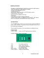
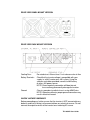
TRANSDUCTION
USER’S MANUAL
Version 1.0
07/30/08
TR-1000VA Pure Sine Wave Inverter
with AC Synchronized Transfer Switch
(+/-) 48 V DC to 110 V AC 50/60 Hz
5155-23 Spectrum Way, Mississauga, ON, Canada L4W 5A1
TEL: 1-800-268-0427, 905-625-1907
FAX: 905-625-0531
Email: [email protected]
Important Information
The information in this document is subject to change without notice.
All relevant issues have been considered in the preparation of this document. Should you notice
an omission or any questionable item in this document, please feel free to notify Transduction.
Regardless of the foregoing statement, Transduction assumes no responsibility for any errors that
may appear in this document nor for results obtained by the user as a result of using this product.
Copyright © 2004 Transduction. All rights reserved.
This document is protected by copyright. No part of this document may be reproduced, copied or
translated in any form or means without prior written permission from Transduction.
All other trademarks, brand and product names are the property of their respective owners.
Return policy
Products returned for repair must be accompanied by a Return Material Authorization (RMA)
number, obtained from Transduction prior to return. Freight on all returned items must be
prepaid by the customer. The customer is responsible for any loss or damage caused by the
carrier in transit.
To obtain an RMA number, call us at 905-625-1907. We will need the following information:
•
Return company address and contract
•
Model name, model number and serial number
•
Description of the failure
Mark the RMA number clearly on the outside of each box, include a failure report and return the
product to:
Transduction
5155 – 23 Spectrum Way
Mississauga ON Canada L4W 5A1
Attn: RMA Department
Index
Safety Precautions ..........................................................
General Features ............................................................
Introduction ......................................................................
Front Panel ......................................................................
Rear View Panel Mount Version .......................................
Rear View Rack Mount Version ........................................
Quick Hookup and Testing ...............................................
Installation ........................................................................
TR-1000VA Rack Mount Version .......................................
TR-1000VA Panel Mount Version ......................................
Operation ..........................................................................
DIP Switch Functions and AC Transfer Switch .................
Specifications ....................................................................
For Service and Support Contact ......................................
1
2
2
2
3
3
4
4
5
5
6
7
9
9
Safety Precautions
WARNING!
Before installing and using your inverter, please read the
safety precautions.
General Safety Precautions
Do not expose the inverter to rain, snow, spray, bilge or dust. To
reduce risk of hazard, do not cover or obstruct the ventilation
openings.
To avoid risk of fire and electrical shock, make sure that existing
wiring is in good electrical condition and that wire size is not
underrated. Do not operate the inverter using damaged or
substandard wiring.
Explosive Gas Precautions
This equipment contains components which can produce arcs or
sparks. To prevent fire or explosion, do not install inverter in any
compartments containing batteries or flammable materials, or in
locations which require ignition protected equipment. This includes
any space containing gasoline powered machinery, fuel tanks, and
any fittings or other connections between components of the fuel
system.
Precautions when working with batteries
If battery acid contacts skin or clothing, immediately wash with soap
and water.
If acid enters the eye, immediately flush eye with cold, running
water and keep flushing it for at least 20 minutes. Seek medical
attention immediately.
NEVER smoke, allow sparks or open flames near the battery or
engine.
Do not drop metal tools on the battery. The resulting spark or short
circuit may cause an explosion.
Remove personal jewelry items when working with lead acid
batteries. The short circuit current produced is high enough to
cause severe burns.
1
TR-1000VA User Guide
GENERAL FEATURES
Microprocessor based design with absolutely accurate and stable frequency
Switch selectable 50Hz or 60Hz output on all models
Very low harmonic distortion THD<3%
Standard input 48V DC
Isolated input / output for for +48V or -48V DC battery systems
Standard output 110V, 50~60Hz
Remote Control Unit (optional accessory)
Power Saver
Panel indicators for battery voltage and load level
Compact and light weight, yet rugged and vehicle rated, 83 ~ 90% efficient
Built-in, fast acting AC synchronized transfer switch (<10mSec)
INTRODUCTION
The TR-1000VA power inverters are some of the most advanced mobile AC
power systems available. To get the most out of the power inverter, it must
be installed and used properly.
Please read the instructions in this manual before installing and using.
FRONT PANEL
ON/OFF Switch:
Leave in the OFF position during installation
POWER SAVING: Energy saving mode
OVP:
UVP:
OTP:
OLP:
BATT VOLTS:
LOAD% WATTS:
Over voltage protection
Under voltage protection
Over temperature protection
Over load protection
Displays input voltage
Displays AC load wattage
2
TR-1000VA User Guide
REAR VIEW PANEL MOUNT VERSION
REAR VIEW RACK MOUNT VERSION
Cooling Fans:
Battery Terminals:
Ground:
Do not obstruct. Allow at least 1 inch clearance for air flow
Check that the inverter voltage is compatible with your
supply i.e. a 48V inverter on a 48V system. Using the
spanner and cables provided, connect to 48V battery
or other 48V power source.
NOTE: Reverse polarity connection will blow internal
fuses and may permanently damage the inverter.
Chassis ground or to vehicle chassis using 8AWG wire.
NOTE: Operation without a proper ground connection may
result in electrical hazard.
SHOCK HAZARD WARNING!!
Before proceeding any further, ensure that the inverter is NOT connected to any
batteries and that all wiring is disconnected from any electrical sources. Do not
connect the output terminals of the inverter to an incoming AC source.
3
TR-1000VA User Guide
QUICK HOOKUP AND TESTING
To check performance before proceeding with the installation, do the following:
1.
Unpack and inspect the inverter. Make sure the power switch is in the
OFF position
2.
First connect the DC negative cable to the negative terminal on the
battery and then connect the cable to the NEG- terminal on the
inverter. The connection on the inverter must be last. There may be a
spark when this final connection is made.
3.
Make sure that all DC connections are tight. Loose connections will
overheat and could result in a potential hazard.
4.
Before proceeding further, double check that the cable you have just
connected to the NEG- terminal of the inverter is connected to the
negative output terminal of the power source.
NOTE: Reverse polarity connection will blow a fuse on the inverter and
may cause permanent damage. Damage caused by reverse polarity
connection is not covered under warranty.
5.
Connect the cable from the POS+ terminal of the inverter to the
positive terminal of the power source. Make sure the connection is
secure. There may be a spark since current may flow to charge
capacitors in the inverter.
6.
Turn ON the inverter and check the indicators on the front panel. The
BATT VOLTS should show a reading. If it does not, check your power
source and the connections. The other indicators should be off.
7.
Turn OFF the inverter. The indicator lights may blink and the internal
alarm may sound briefly. This is normal. Plug the test load in to the AC
receptacle on the front panel of the inverter. Leave the test load switch
off.
8.
Turn ON the inverter and turn ON the test load. The inverter should
supply power to the load. To measure the true output r.m.s. voltage of
the inverter, a meter must be used.
INSTALLATION
The TR-1000VA should be installed in a location that meets the following
requirements:
DRY
Do not allow water to drip or splash on the inverter
COOL
Ambient air temperature should be between 0EC and 50EC.
The cooler the better.
SAFE
Do not install in a battery compartment or other areas where
flammable fumes may exist.
VENTILATED
Allow at least 1 inch of clearance around the inverter for
air flow. Ensure that ventilation openings are not obstructed.
DUST-FREE
Do not install in a dusty environment.
4
TR-1000VA User Guide
TR1000VA RACK MOUNT VERSION showing installation of chassis slides
TR1000VA PANEL MOUNT VERSION
AC Safety Grounding:
During the AC wiring installation, AC input and output ground wires are connected to the
Inverter. The AC input ground wire must connect to the incoming ground from your AC
utility source. The AC output ground wire should go to the grounding point for your loads.
5
User Guide
TR-1000VA
Neutral Grounding:
The neutral conductor of the AC output circuit of the Inverter is automatically
connected to the safety ground during Inverter operation. This conforms to
National Electric Code requirements. For models configured with a transfer
relay, when AC power is present and the Inverter is in bypass mode, this
connection is not present and so conforms to code requirements.
Ground Fault Circuit Interrupters (GFCI’s):
Installations in recreational vehicles will require GFCI protection of all circuits
connected to the AC output of the Inverter.
Connecting Battery Cables to the DC Input Terminals:
Cables should be less than 10 feet long (3 meters) and the correct gauge to
handle the required current, in accordance with the codes/regulations applicable to your installation. Incorrect cabling will decrease Inverter performance
and may cause poor surge handling, voltage warnings and shutdowns.
OPERATION
ON/OFF
Simply turn ON the Inverter and it is ready to deliver AC power. If operating more
than one load from the Inverter, turn them on separately after the Inverter has been
turned on. NOTE: Turning OFF the Inverter does not disconnect the power source
from the Inverter.
The Inverter operates from the following AC input voltage ranges:
42 to 62 V DC ( positive or negative ground )
Battery Voltage Indicator:
The battery voltage bar graph indicates voltage at the input terminals of the
Inverter, at low current input and is very close to the battery voltage. At high
input current, this voltage will be lower than the battery voltage because of the
voltage drop across the cable and connections. Ideally, the voltage should
remain in the green areas of the bar graph. If it goes in to the red at top or
bottom of the bar graph, the Inverter may shut down.
Load Watt Indicator:
The AC load watt bar graph shows the power drawn from the Inverter. It will
indicate watts by load. For long term operation, this should be in the green and
orange. Short term operation in the red is possible. If this indicator flashes the
entire bar graph the Inverter will shutdown to protect itself.
6
TR-1000VA User Guide
OVP Over Voltage Indicator:
Indicates inverter shutdown due to input voltage over the 48V DC limit.
UVP Under Voltage Indicator
Indicates shutdown due to input voltage less than 48V DC.
OTP Over Temp Indicator
Indicates shutdown due to overheating. This may occur if the inverter is
operated at power levels above its rating or if installed so that heat cannot
dissipate properly. It will restart automatically once it has cooled down.
OLP Overload Indicator
Indicates shutdown because output circuitry has been shorted or drastically
overloaded. Switch to OFF, correct the fault condition and switch back to ON.
DIP SWITCH FUNCTIONS AND AC TRANSFER SWITCH (refer to table below)
DC/AC Out Mode
AC output power is supplied by DC/AC. AC Transfer Switch is on. No power
saving function.
DC/AC + Power Saving Mode
AC output power is supplied by DC/AC. AC Transfer Switch is on. When AC
output load is turned off, DC/AC will go into power saving mode and reduce
battery consumption.
UPS Mode
When power is supplied by AC input, the AC Transfer Switch is off and DC/AC
is in stand-by mode. If this supply of power is cut off, the AC Transfer Switch
will switch to on (10mSec delay) and AC output will be supplied by DC/AC.
When AC input is back to normal, the AC Transfer Switch will change back to
off.
NOTE: A change of +15% in the AC input power will also initiate UPS Mode.
UPS Mode + Delay Mode + Power Saving
Same as UPS Mode but with 5mSec delay. With AC input power, the AC output
is by DC/AC, but when the AC output load is turned off, then the DC/AC will
switch to power saving mode.
7
TR-1000VA User Guide
DIP Switch (110V)
S1
S2
Function
S3
S4
Output
voltage
S5
Output
Frequency
OFF
OFF
DC/AC OUT MODE
OFF
OFF
120V
OFF
60Hz
OFF
ON
DC/AC + POW ER
SAVING MODE
ON
OFF
115V
ON
50Hz
ON
OFF
UPS MODE
OFF
ON
110V
ON
ON
UPS MODE + DELAY MODE
+ POW ER SAVING
ON
ON
100V
AC Transfer Switch
8
TR-1000VA User Guide
SPECIFICATIONS
Model
TR1000VA-48
Continuous output power
1000W
Output power surge
1400W
AC Output Voltage
100/110/120V ±2%, 220/230/240V ±2%, DIP switch selectable
Output voltage regulation
-8% ± 3%
Output frequency
50/60Hz selectable, ±0.05% accuracy
Output wave form
Pure Sine Wave <3% THD
Efficiency (full load)
83 - 85%
No Load power consumption
<1.5W (in power saving mode)
Input voltage range
44 ~ 56VDC
Power saving recovery time
1 second
AC transfer time (UPS mode)
<10mSec max
LED status indicators
High/Low battery shutdown, over temperature shutdown, overload
shutdown, input DC voltage scale meter, output watts % scale meter
Protection features
*Remote controller is optional
Overload, short circuit, over/under input voltage, over temperature,
reverse input polarity (by fuse)
RS485 Remote Controller
(optional)
Power output ON/OFF, power saving mode, reset, error messages
and more
Operation temperature range
0~40°C (32~104°F)
Dimensions (LxWxH)
Rack mount 15.75" x 19" x 3.5"
Panel mount 15.75" x 9.81" x 3.87"
Weight
Rack mount 22.5 Lb (10.25 Kg)
Panel mount 12.13 Lb (5.5 Kg)
Warranty
Two year warranty, F.O.B. Transduction
FOR SERVICE AND SUPPORT CONTACT:
Transduction
5155 Spectrum Way, Bldg 23
Mississauga, ON L4W 5A1 Canada
Tel: 905-625-1907
Fax: 905-625-0531
email: [email protected]
9
TR-1000VA User Guide