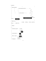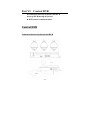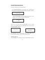
1
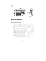
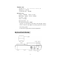
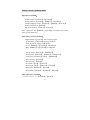
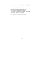
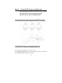
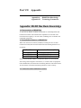
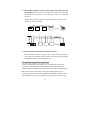
KEYBOARD
CONTROLLER SYSTEM
Please read user manual carefully before installing or
operating the unit
Notes:
Manufacture can offer international certification
and CO.
This copyright belongs to my company, any companies or individual
can not
copy the content without permission.
Design and Specification are subjected to change without notice.
-1-
Content
Part I
Introduction ------------------------------------------------- 4
Keyboard introduction ------------------------------------------------- 4
Keyboard Function ------------------------------------------------------ 4
Working mode option --------------------------------------------- 4
Language option -------------------------------------------------- 4
Communication port ---------------------------------------------- 4
Matrix working mode --------------------------------------------- 5
P/T working Mode ------------------------------------------------- 5
DVR working Mode ----------------------------------------------- 5
Combined control Mode ------------------------------------------ 6
Buzzer ---------------------------------------------------------------- 6
Application ---------------------------------------------------------- 6
Part II
Installation and Connection
Accessory --------------------------------------------------------------------- 7
Size ----------------------------------------------------------------------------- 8
Keyboard Explanation --------------------------------------------------- 8
Keyboard Front Sketch ------------------------------------------- 8
Keyboard Back Sketch ------------------------------------------- 9
Back Port Function Explanation ----------------------------- 10
Power On ------------------------------------------------------------------- 10
Keyboard Hint ------------------------------------------------------------- 11
Part III
Keyboard Setting
Keyboard Setting ------------------------------------------------------ 12
How to set up ----------------------------------------------------------- 12
Menu Index ------------------------------------------------------------- 12
-2-
Part IV Keyboard Control Matrix
Connection between Keyboard and matrix ---------------------- 15
Control matrix through keyboard---------------------------------- 16
Matrix control commands index ------------------------------------ 18
Part V Control PTZ Camera and Decoder
Connection between keyboard and PTZ camera---------------- 20
Control PTZ camera through keyboard -------------------------- 20
PTZ Camera control command index ----------------------------- 22
Part VI
Control DVR
Connection between keyboard and DVR ------------------------- 24
Set up DVR through keyboard -------------------------------------- 25
DVR control commands index -------------------------------------- 26
Part VII
Appendix
Appendix A RS485 Bus basic Knowledge ---------------------- 28
Appendix B Technology Parameters ---------------------------- 31
-3-
Part I
Introduction
■Brief
■Function
■Application
Keyboard Brief
The keyboard is characterized with mini size, it is very suitable for
small place project, such as mobile P/T control, sub-control, small
surveillance project, and so on.
The keyboard can control other control equipments, not only it can
control my company matrix, but also can control other brand DVR,
or connect to PTZ camera or decoder with multi-protocol.
The keyboard has built-in LCD screen, the displayed information
would be wonderful.
Keyboard Function
Working Mode Option
The keyboard can set up matrix working mode and DVR working
mode, it is very convenient to operate surveillance system in project.
Language option
Chinese and English LCD display, user can choose language according
to requirement.
Communication Port
The keyboard offers 1 pcs RS-485 communication port and support
semi duplex two ways communication, and it can offer one pcs of
DC 12V power input port and 1 pcs of COM port ( COM port offer
-4-
power supply and RS485 communication through connecting RJ45
port).
Matrix working Mode
When Keyboard working mode is matrix working mode,RS485 port
can be used to connect to matrix switcher, the keyboard not only control
matrix switcher, but also control PTZ camera, decoder, alarm
equipments and assistant equipments.
P/T Working Mode
When keyboard working mode is P/T working mode,RS485 port is
connected to PTZ camera and decoder, or other related equipments,
The keyboard can choose different communication protocols and baud
rates, so that it can connect to other front equipments, the function user
can use as follow: DVR related function, camera’s P/T control, camera
zoom in and out, turn on or turn off auxiliary switchers, to set up or
pick up auto scanning function, set up PTZ camera’s parameters… and
so on.
DVR Working Mode
When keyboard working mode is in DVR working mode, RS485 port
can connect to DVR, NVS. The keyboard can choose different
communication protocols and baud rates, so that it can connect to other
front equipments, the function user can use as follow: DVR related
function, camera’s P/T control, camera zoom in and out, turn on or
turn off auxiliary switchers, to set up or pick up auto scanning function,
set up PTZ camera’s parameters… and so on.
-5-
DVR related function includes:
Normal function: control DVR to record, play, pause, speed, playback,
stop .
Advanced function: recording speed setup, audio search, alarm
scanning and search, menu setting.
Combined Control Mode
In order to control different style of equipments at the same time, the
keyboard offer combined control mode. When keyboard is connected
to PTZ camera or decoder and DVR, users don’t need to switch
control mode to control every equipments.
Multi-function key of keyboard should be suitable for combined
control mode, for which keyboard control multi-DVR to record, play,
pause, speed, playback, stop and camera control and joystick control
is suitable for PTZ camera and decoder.
Buzzer
Keyboard has built-in buzzer which can indicate operation of pressing
keys. When it was connected to matrix switcher, it is also applied on
monitor alarm, if there is association alarm in the system, buzzer can
respond to association alarm, the buzzer can be set into ON or OFF
according to requirement, or prohibit to use it.
Application
This keyboard can control my company series of matrix switcher, it is
compatible with decoder or PTZ camera with multi-protocol, and
support alarm association and DVR recording, when whole system is
internet system, the keyboard can be used as internet keyboard to
control all equipments which can receive communication control.
-6-
Part II
Installation, Connection and Setting
■Accessories
■Size
■Introduction
■Power On
■Keyboard hint
Installation, Connection and Setting
1) Only qualified and experienced person can carry on this installation
2) Before installation, please check all accessories, if there is
something missed, please give your feedback to supplier in time, in case
the keyboard can not work well.
Accessory:
Keyboard: 1 set.
Connection port: 1 piece.
Power: 1 set (AC110/220V input DC12V/500mA output).
User Manuel: 1 piece.
Warranty card: 1 piece.
-7-
Size:
Keyboard Explanation:
Keyboard front Sketch:
-8-
Number area:
Number key:1、2、3、4、5、6、7、8、9、0
Delete key:CANCEL
Confirmation key:ENTER
Function Area:
P/T Key:PRESET、AUTO、SCAN
Matrix Key:NEXT、AUTO、ENTER
Accessory:AUX
Alarm:ALARM
Special Function:F1
Assistant Function Key: SHIFT
Joystick: To control PT up and down, left and right; camera
zoom in and out; the angle of control joystick can control
P/T moving speed.
LCD Screen: display data of control equipments.
Keyboard back Sketch:
-9-
Back Port function introduction:
RS485 Port: Connect to communication port of other equipments.
Power Port:(12V/500MA)
COM Port: offer power and RS485 through RJ45
Green indicator:the light would be normally on when user set up
matrix working mode and P/T working mode,
if there is command sent to keyboard, the light
would be glittered.
Yellow indicator: the light would be normally on when user set up
matrix working mode and DVR working mode,
when user control DVR through keyboard, the
light would be glittered.
Power on
Before offering power to keyboard, kindly please check whether
power of keyboard is accordance with offered power, and check
whether keyboard input power is DC12V/500mA.
Power on:
1、The keyboard will sound “di”, it proves user has offered power
to keyboard successfully.
2、The relative indicator would be normally on.
3、LCD screen would display keyboard working mode, control
protocol, baud rate:
Working Mode: DVR
P:HIKVIS
B:9600
- 10 -
Keyboard hint:
1、Indicator explanation:
If indicator is on, it shows keyboard is powered on, and it
works under some mode, when there are commands sent to
keyboard, indicator will glitter.
2、Sound hint:
“Di” one time, It show user is operating keyboard
“Di,Di,Di” three times, it shows operation is wrong
“Di Di Di…”continuously sound, alarm happens.
3、Alarm display hint
When system give alarm signal, LCD will display as follow:
ALARM=> No:= address area
NN = DDDD ZZZZ
When system give alarm signal for several monitored spot,
alarm Series Number NN, alarm address DDDD, alarm Zone
ZZZZ, display alarm spot circularly.(note: display max up to
10 alarm spots)
- 11 -
Part III
Keyboard setting
■Setting Key
■Setting Procedure
■Menu Index
Keyboard Setting
The keyboard offer several kinds of working mode, joystick parameter
correction setting, each key function.
Setting key
【CANCEL】
【ENTER】
【F1】
【SHIFT】
delete key
confirmation key
special function key
assistant function key
How to set up
To press【SHIFT】+【F1】 at the same time,then make keyboard power
on , it will enter into keyboard menu setting within 5 seconds.
To press 【F1】 to enter into menu option, to press【CANCEL】exit
menu;To press【ENTER】to confirm setting information;
Menu Index:
|keyboard working mode option | matrix working mode | protocol
option…|factory protocol
|
|
|Master/Sub-keyboard choose……|→master
- 12 -
keyboard
|
|
|
|→Sub-keyboard
|
|
|→sub-keyboard choose………….|→1
|
|
|
|→2
|
|
|
|→…
|
|
|
|→16
|
|
|→alarm choose…-----…
|→1
|
|
|→2
|
|
|→…
|
|
|→239
|
|→P/T working Mode|→protocol
choose…|→PELCO_D
|
|
|→PELCO_P
|
|→DVR working mode-|→protocol
choose……|→Hikvision
|
|→Dahua
|
|→…
|→baud rate option……|→9600
|
|→4800
|
|→2400
|
|→1200
|→sound option……|→ON
|
|→OFF
|→BLC control……|→Auto
|
|→Normal Open
|
|→OFF
|→language……|→Chinese
- 13 -
|
|→English
|→Joystick setting……|→press【CANCEL】to exit
|
|→press【5】to get standard
|
|→press【2】to maximum
|
|→press【0】to maximum
|
|→press【4】left to maximum
|
|→press【6】right to maximum
|
|→press【7】left to maximum
|
|→press【9】right to maximum
|→press key testing|→press【CANCEL】to exit
|
|→press other key to shows
|→default setting……|→confirmation
|
|→give up
|→software version……|→Version 1.0
Note:Menu option with Remarked“XX”is default setting.
- 14 -
Part IV
Keyboard Control Matrix
■Control matrix through keyboard
■Connection between Keyboard and matrix
■matrix control command index
Control matrix through keyboard
The keyboard can control all series of matrix switcher from my
company(M2000L/M/E/S), if there is matrix switcher from the third
party which has my company communication, it can also control other
matrix.
Connection between Keyboard and matrix
- 15 -
Control matrix through keyboard
To choose working mode and control protocol:
To press【SHIFT】+【F1】keys synchronously,then make
keyboard power on, user will enter into keyboard setting menu
after 5 seconds.
Keyboard setting Menu
1. Working Mode
To press【ENTER】to enter into working mode setting; to press
【F1】to choose matrix working mode:
- 16 -
1. Working Mode
1> Matrix
When user see matrix working mode, then press【ENTER】to enter into
related option of matrix working mode;to press【F1】to choose control
protocol, press【ENTER】to confirm it.
1. Matrix mode
1) control protocol
1. Control protocol
Default protocol
---------→
To press【F1】to choose ”default protocol”, to press【ENTER】 to save
it; to press【CANCEL】to back to ”keyboard setting menu”.
To choose baud rate:
To press【F1】to choose baud rate, then press【ENTER】to enter into baud
rate setting:
Keyboard setting Menu
2.Baud rate setting
Keyboard setting Menu
1. Working Mode
→
2. Baud rate setting
9600 Bit/S
To press 【F1】 to choose “9600”, to press【ENTER】 to confirm it;
to press【CANCEL】to exit setting menu.
- 17 -
Matrix control command index
Operation commands:
Switch camera:【number】+【ENTER】
Switch monitor:【number】+【SHIFT】+【ENTER】
Camera sequence switch:【number】+【SHIFT】+【AUTO】
Switch camera back:【NEXT】
Switch camera front:【SHIFT】+【NEXT】
Note:when user uses【SHIFT】, please keep pressing this key, at the
same, to press other keys.
PTZ camera control command:
Right and left:【joystick】 move to left or right
Up and down:【Joystick】move up and down
Zoom in and out:【Joystick】rotation
Focus:【SHIFT】+【Joystick】 left and right
IRIS:【SHIFT】+【Joystick】Up and down
Pick up preset:【number】+【PRESET】
Set up preset:
【number】+【SHIFT】+【PRESET】
Clear preset:
【number】+【F1】+【PRESET】
Auto scanning:【AUTO】
Run scanning:【AUTO】
Set up left l:
【F1】+【AUTO】
Set up right:
【F1】+【SHIFT】+【AUTO】
Preset tour:【number】+【SCAN】
Run pattern:
【number】+【SHIFT】+【SCAN】
Other operation commands:
Auxiliary function on: 【number】+【AUX】
- 18 -
Auxiliary function off: 【number】+【SHIFT】+【AUX】
Notes:
Auxiliary function 【Number】: 1. heater 2. windshield wiper 3. Light
( The function is related with the equipments used)
Alarm function on: 【number】+【ALARM】
Alarm function off: 【number】+【SHIFT】+【ALARM】
Alarm cancel: 【SHIFT】+【CANCEL】
Note: Alarm function 【number】: Alarm address
- 19 -
Part V Control PTZ Camera and Decoder
■ Connection between keyboard and PTZ camera
■ Control PTZ camera through keyboard
■ PTZ Camera control command index
Connection between keyboard and PTZ camera
Control PTZ camera through keyboard
Select the working mode and control protocol
Press 【SHIFT】+【F1】at the same time, then make power on, then enter
into keyboard setting menu after 5 minutes.
- 20 -
Keyboard setting menu
1.working mode
Press 【ENTER】to enter into working mode setting; press 【F1】to
choose keyboard and PTZ working mode
1.working mode
2..PTZ
When LCD displays PTZ mode, to press 【ENTER】to enter into
related PTZ mode;to press 【F1】to choose default protocol, To
press【ENTER】to confirm setting information;
1)control protocol
2) PTZ mode
PELCO-D
1)control protocol
To press【F1】to select default protocol, to press【ENTER】to confirm
it; To press 【CANCEL】menu to exit to “keyboard setting menu”
To choose baud rate:
To press 【F1】to choose baud rate, to press 【ENTER】 to enter into
baud rate setting:
- 21 -
Keyboard setting menu
Keyboard setting menu
1. working mode
→
2.baud rate setting
2. baud rate setting
9600 Bit/S
To press 【F1】to choose baud rate, To press 【ENTER】to confirm
setting information; To press 【CANCEL】menu to exit to keyboard
setting menu.
PTZ Camera control command index
PTZ Camera control command
P/T Right and left:【joystick】 move to left or right
P/T up and down:【Joystick】move up and down
lens zoom :【Joystick】rotation
Lens Focus:
【SHIFT】+【Joystick】 left and right
Lens Iris:【SHIFT】+【Joystick】Up and down
Pick up preset:【number】+【PRESET】
Set up preset:
【number】+【SHIFT】+【PRESET】
Clear preset:
【number】+【F1】+【PRESET】
Auto scanning:【AUTO】
Run scanning:【AUTO】
Set up left :
【F1】+【AUTO】
Set up right :
【F1】+【SHIFT】+【AUTO】
Run Preset tour:【number】+【SCAN】
Run pattern:
【number】+【SHIFT】+【SCAN】
- 22 -
Note: User need to keep pressing【SHIFT】key, then press other
function keys, setting would be valid.
Other operating commands:
Auxiliary function on: 【number】+【AUX】
Auxiliary function off: 【number】+【SHIFT】+【AUX】
Note:
Auxiliary function 【Number】: 1. heater 2. windshield wiper 3. Light
( The function is related with the equipments used)
Alarm function on: 【number】+【ALARM】
Alarm function off: 【number】+【SHIFT】+【ALARM】
Alarm cancel: 【SHIFT】+【CANCEL】
Note: Alarm function【number】: Alarm address
- 23 -
Part VI
Control DVR
■ Connection between keyboard and DVR
■ Set up DVR through keyboard
■ DVR control commands index
Control DVR
Connection between keyboard and DVR
- 24 -
Set up DVR through keyboard
To choose working mode and control protocol:
To press【SHIFT】+【F1】keys synchronously,then make keyboard
power on, user will enter into keyboard setting menu after 5 seconds.
Keyboard setting Menu
1. Working Mode
To press【ENTER】to enter into working mode setting; to press
【F1】to choose keyboard and PTZ working mode:
2. Working Mode
3)
DVR
When user see P/T mode, then press【ENTER】to enter into related
option of P/T working mode;to press【F1】to choose control protocol,
press【ENTER】to confirm it.
3. DVR mode
1) control protocol
1.Control protocol
HIKVISON
---------→
To press【F1】to choose ”default protocol”, to press【ENTER】 to save
it; to press【CANCEL】to exit to ”keyboard setting menu”.
To choose baud rate:
To press【F1】to choose baud rate, then press【ENTER】to enter into
- 25 -
baud rate setting:
Keyboard setting Menu
2.Baud rate setting
Keyboard setting Menu
1. Working Mode
→
2. Baud rate setting
9600 Bit/S
To press 【F1】 to choose default baud rate, to press【ENTER】
to confirm it;to press【CANCEL】to exit keyboard setting menu.
DVR control commands index
DVR control commands::
Picture monitor:【 】
Image Browsing:【SHIFT】+【 】
Multi-Image switch【number】+【 】
The begining:
【 】
The end:【SHIFT】+【 】
FF:【 】
REW:【SHIFT】+【 】
Pause:【 】
Play:【SHIFT】+【 】
Stop:【 】
Videotape:【SHIFT】+【 】
Note: User need to keep pressing【SHIFT】key, then press other
- 26 -
function keys, setting would be valid.
PTZ camera control command:
Ptz right and left:【joystick】 move to left or right
Ptz up and down:【Joystick】move up and down
Zoom in and out:【Joystick】rotation
Focus:【SHIFT】+【Joystick】 left and right
IRIS:【SHIFT】+【Joystick】Up and down
Pick up preset:【number】+【PRESET】
Set up preset:
【number】+【SHIFT】+【PRESET】
Clear preset:
【number】+【F1】+【PRESET】
Auto scanning:【AUTO】
Run scanning:【AUTO】
Set up left l:
【F1】+【AUTO】
Set up right:
【F1】+【SHIFT】+【AUTO】
Preset tour:【number】+【SCAN】
Run pattern:
【number】+【SHIFT】+【SCAN】
Other operation commands:
Auxiliary function on: 【number】+【AUX】
Auxiliary function off: 【number】+【SHIFT】+【AUX】
Notes:
Auxiliary function 【Number】: 1. heater 2. windshield wiper 3. Light
( The function is related with the equipments used)
Alarm function on: 【number】+【ALARM】
Alarm function off: 【number】+【SHIFT】+【ALARM】
Alarm cancel: 【SHIFT】+【CANCEL】
Note: Alarm function 【number】: Alarm address
- 27 -
Part VII
Appendix
Appendix A
Appendix B
RS485 Bus Knowledge
Technology Parameters
Appendix: RS485 Bus Basic Knowledge
1. Characteristics of RS485 Bus
As specified by RS485 standards, RS485 Bus is of half-duplexed data
transmission cables with characteristic impedance as 120 Ohm. The
maximum load capacity is 32 unit loads (including main controller and
controlled equipment).
2. Transmission distances of RS485 Bus
When user selects the 0.56mm (24AWG) twisted pair wires as data
transmission cable,the maximum theoretical transmitting distances are
as follows:
Baud Rate
2400bps
4800bps
9600bps
Transmission Distance (Max.)
5,906ft (1800m)
3,937ft (1200m)
2,625ft (800m)
If user selects thinner cables, or installs the dome in an environment
with strong electromagnetic interference, or connects lots of equipment
to the RS485 Bus, the maximum transmitting distance will be decreased.
To increase the maximum transmitting distance, do the contrary.
3. Connection and termination resistor
- 28 -
3-1.The RS485 standards require a daisy-chain connection between
the equipment. There must be termination resistors with 120 Ohm
impedance at both ends of the connection (refer to following
pictures).
Please refer to below picture for simple connection. Distance “D”
should not exceed 7 meters.
1 20Ω
1 2 0Ω
1#
2#
A+
B-
4#
3#
3 2#
.. .. ..
D
A+
M ain contro ller
B-
1#
2#
3#
3 1#
3-2 The connection of 120 Ohm termination resistor:
The termination resistor is ready on the Protocol PCB. There are
two kinds of connection. Please refer to the Protocol PCB jumper
setting form (refer to following pictures).
4. Problems in practical connection
In some circumstances user adopts a star configuration in practical
connection. The termination resistors must be connected to the two
equipment that are farthest away from each other, such as equipment 1#
and 15# in the Picture as below. As the star configuration is not in
conformity with the requirements of RS485 standards, problems such as
signal reflections, lower anti-interference performance arise when the
- 29 -
cables are long in the connection. The reliability of control signals is
decreased with the phenomena that the dome does not respond to or just
responds at intervals to the controller, or does continuous operation
without stop ( refer to the following picture).
1#
6
M #
a
C
on i n
tro
ll e
r
32#
15#
In such circumstances the factory recommends the usage of RS485
distributor. The distributor can change the star configuration connection
to the mode of connection stipulated in the RS485 standards. The new
connection achieves reliable data transmission (refer to following
picture).
- 30 -
Appendix B
LCD display
Joystick
HIDD
Baud rate
Power supply
Power
Technology Parameters
Chinese/English
Three dimension
RS485 half duplex
1200、2400、4800、9600
DC129V/500mA
5W
- 31 -