1
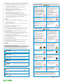
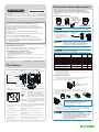
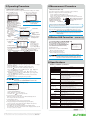
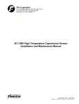
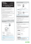
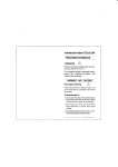
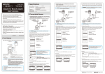
GL100-UM-851 GL100 Series GL100-N/GL100-WL Quick Start Guide 604309261 (3) Using this GL100 in the following environments may cause inaccurate measurements or damage: • Places with high temperatures or high humidity, such as direct sunlight and heaters. Allowable temperature range: -10 to 50°C, allowable humidity range: 0 to 80% RH, non-condensing If Condensation Occurs Condensation occurs in the form of water droplets on the device surfaces and interior when the GL100 is moved from a cold location to a warm one. Using the GL100 with condensation will cause the GL100 to malfunction. Wait until the condensation has evaporated before turning on the power. MANUAL-GL100-E CAUTION Please read this manual thoroughly before attempting to use this GL100 Petit LOGGER to ensure that you use it correctly. Notes on Use Be sure to read all of the following notes before attempting to use the GL100 Petit LOGGER. 1. Note on the CE Marking The GL100 Petit LOGGER complies with the following standards. • EN 61326-1 (Class A) standard based on the EMC directive (2004/108/EC) • EN 61010-1:2010 3rd standard based on the LVD directive (2006/95/ EC) • EN 301 489-17/-1, EN 300 328 standards based on the R&TTE directive (1999/5/EC) Although the GL100 complies with the above-mentioned standards, be sure to use it correctly in accordance with the instructions and notes provided in this manual. Moreover, use of the GL100 by incorrect procedures may result in damage to the GL100 or may invalidate its safeguards. Please confirm all of its notes regarding use and other related information to ensure correct use. 2. Warning This is a Class A product according to the EMC directive. In a domestic environment, this product may cause radio interference or may be affected by radio interference to the extent that proper measurement cannot be performed. 3. Notes on Radio Law This GL100-WL contains a wireless module that Radio Law certified. Make sure to note the following points: not remove the technical standards compliance label. Do not use • Do the device if it does not have a label on it. GL100 uses the 2.4GHz frequency band. • This The following devices and transmitters use the same frequencies and • should not be used near this GL100: • Microwave ovens • Pacemakers and other industrial, science, and medical devices • Radio transmitters used in mobile body identification devices on factory production lines, etc. (transmitters requiring licensing) • Specified low-power radio transmitters (transmitters not requiring licensing) Communications may become slower or impossible due to radio interference. The signal may be weak or communications may become slower or impossible depending on the circumstances this GL100 is used in. Take particular note of steel-reinforced, metal, concrete, and other structural materials that can inhibit radio waves. GL100 is meant for use in Japan, the US, and Europe. It has not • This been certified for use under any other country’s radio laws. The following are each region’s certification marks. Japan US R 201-135002 Canada Contains IC ID:9154A-GS1011MIPS Contains FCC ID:YOPGS1011MIPS Europe CE Mark 4. Notes for Safe Operation (1) When connected to high-voltage signal through an analogue signal from 4ch voltage / temperature terminal (GS-4VT), do not touch the central line of the input terminal’s signal line. There is a risk of electric shock due to high voltage. 5. Notes on Functions and Performance (1) Use AA alkaline batteries. Using other types of batteries may cause damage to the device. (2) Using the module, sensor, etc. with the vent hole covered may result in inaccurate measurements. When Temperature and humidity sensors (GS-TH) and GL100-N/GL100-WL are used at the same time, they should be used in the GL100-N/GL100-WL operating environment. • Locations subject to excessive salt spray or heavy fumes from corrosive gas or solvents. • Excessively dusty locations. • Locations subject to strong vibrations or shock. • Locations subject to surge voltages and/or electromagnetic interference. (4) If the GL100 becomes soiled, wipe it off using a soft, dry cloth. Do not use the organic solvents (such as thinner or benzene). (5) Do not use the GL100 in the vicinity of other devices which are susceptible to electromagnetic interference. (6) Measured results may not conform to the stated specifications if the GL100 is used in an environment which is subject to strong electromagnetic interference. (7) Position the input signal cables as far away as possible from any other cables which are likely to cause electromagnetic interference. (8) GS-TH Temperature and Humidity Sensors: • Humidity sensors measure the change in dielectric capacity of water adsorption. As a result, humidity from organic materials such as fine particles or exhaust gas may have an effect on the sensor. Use in environments with large quantities of these organic materials may lead to significant measurement inaccuracies. (9) GS-CO2 CO 2 Sensor: • Because exhaled CO 2 may have an effect on the sensor readings, do not use the sensor to take measurements near the face. Additionally, should air flow to the sensor be blocked, it will result in inaccurate readings, so be sure to keep vent holes open. (10) GS-LXUV Illumination / Ultraviolet Sensor • When measuring illumination or ultraviolet light that can have harmful effects on the eyes or skin, be sure to use protective eyewear, shielding, etc. • If the sensor becomes dirty it may affect measurements, so wipe it with a soft cloth when it becomes dirty. • Take care to avoid cracking the sensor when handling it. If the sensor is damaged or cracked it may affect measurements, so replace the sensor. (11) Others • The GS-TH temperature and humidity sensor, the GS-CO2 CO 2 sensor, and the S-LXUV illumination / ultraviolet sensor may gradually deteriorate over time depending on usage circumstances and environment, so we recommend periodically replacing these sensors every year or so. • The GL100-N/GL100-WL units meet IP54 standards when the sensor or sensor module is connected and then the connector cover and battery cover are closed. Note that you cannot use the GL100-N/GL100WL units with devices that do not meet IP54 standards (except for the 3-axis acceleration sensor) when sensors and sensor modules are located in the same environments. Additionally, when there is deterioration or damage to the gasket on the connector cover or battery cover of the GL100-N/GL100-WL, it no longer meets IP54 standards, so be sure to either periodically replace them or have them repaired. • If the non-optional device is connected to the GL100-N/GL100-WL’s module connection terminal or the GS-DPA branch adapter connector, the GL100-N/GL100-WL or branch adapter may be damaged. Please do not connect it. 6. Operating Environment This section explains the operating environment for the GL100. 1) Ambient Temperature and Humidity ( Use the GL100 within the following ranges) • Temperature range: -10 to 50°C • Humidity range: 20% to 80% RH, non-condensing 2) Environment (This GL100 is designed for indoor use. Do not use in the following locations.) • This GL100 meets IP54 standards for simple waterproofing and dustproofing but should not be used in environments that the sensor and/or module are not designed for. • See part (3) of Section 5 (Notes on Function and Performance). 3) Installation Category (Overvoltage Category) • The GL100 belongs to Installation Category II defined in IEC 60664-1. • Never use the GL100 for Installation Category III or IV. 4) Overvoltage Category • Overvoltage categories as defined by IEC 61010 are as follows: GL100-N/GL100-WL: Overvoltage category I When connected to a PC/AC adapter: Overvoltage category II * Be sure to use either a commercially available AC adapter or a PC (with a IEC 60950-1 certified Limited Power Source USB output) with this GL100. * Furthermore, do not use this GL100 with IEC 61010-defined overvoltage category III or IV. 5) Altitude • This GL100 can be used at altitudes up to 2,000m. 6) Power • Two alkaline batteries or a USB cable connection (5V, 200 mA or higher) can be used to provide power. 7) Degree of Contamination • This GL100 is IEC 60664-1-certified for use in up to Contamination Degree 2. 8) Use • This GL100 is intended for use as industrial equipment. Notes on the Use of This Manual (1) All rights reserved. No part of this publication may be reproduced, stored in a retrieval system, or transmitted, in any form or by any means, without the prior written permission of Graphtec Corporation. (2) The specifications and other information in this manual are subject to change without notice. (3) While every effort has been made to supply complete and accurate information about this product, please address any inquiries about unclear information, possible errors, or other comments to your sales representative or nearest Graphtec vendor. (4) Notwithstanding the preceding paragraph, Graphtec Corporation assumes no liability for damages resulting from the use of the information contained herein or of the product. About Registered Trademarks Microsoft and Windows are registered trademarks or trademarks of Microsoft Corporation in the U.S. and elsewhere. Other company names and product names included in this manual are registered trademarks or trademarks of their respective companies. Copyright All copyrights regarding this manual belong to Graphtec Corporation. Conventions Used in This Manual Safety Precautions Do not use the device for unintended purposes. Do not use the device for uses other than measuring. Do not insert foreign objects into the device. Inserting metallic objects or flammable objects into the device may cause an electrical shock or fire. Keep away from children. Do not setup the device in a place within the measuring location that children can reach. They may swallow the device and/or injure themselves. Do not use the device if it is damaged. This can cause an electrical Use prohibited shock or fire hazard. Do not allow the device to get wet. This can cause an electrical shock or fire hazard. Be especially careful when using the device near windows during rain or snow or in coastal areas. Avoid water Never disassemble or remodel the GL100. Modifying this GL100 may cause an electrical shock or fire due to short circuiting No disassembly and generating heat. • • • If fluid or foreign matters enters inside the GL100, turn off the Power switch and disconnect the power cord from the electrical socket. Use in such status may cause a fire hazard due to electrical shock or current leakage. Contact your sales representative or nearest Graphtec vendor to request repair. Use prohibited • This category provides information that, if ignored, is highly likely to cause fatal or serious injury to the operator. WARNING This category provides information that, if ignored, is likely to cause fatal or serious injury to the operator. CAUTION This category provides information that, if ignored, could cause physical damage to the GL100. HIGH TEMPERATURE This category provides information that, if ignored, is likely to cause burns or other injury to the operator due to contact with high temperature. ELECTRICAL SHOCK This category provides information that, if ignored, is likely to expose the operator to electrical shock. • • • • • Do not input voltage that exceeds the permissible input voltage range that is specified on the GL100’s label. Exceeding the specified • voltage input range may cause electrical shock or a fire hazard. • Safety Precautions • • Use the specified batteries. Using the device with other batteries may cause electrical shock or fire hazard. The batteries and exterior of the LOGGER may be very hot. • • HIGH TEMPERATURE Use prohibited CAUTION Do not put the device in any of the following places when installing it: • locations in direct contact with oily smoke or steam • locations with direct sunlight • locations that experience temperatures outside the operating range Putting the device into places like these may cause short circuiting, heat, deformation of the case, electrical shocks, fires and malfunctions. Do not use the device in locations with severe mechanical vibration or large amounts of electrical static. Such location may impair the Prohibited GL100’s performance. To promote safe and accurate use of the GL100 as well as to prevent human injury and property damage,safety precautions provided in this manual are ranked into the five categories described below. Be sure you understand the difference between each of the categories. DANGER WARNING In the event of a malfunction, remove the batteries and do not attempt to use the device. Attempting to use the device when malfunctioning may cause an electrical shock or fire. Remove the batteries immediately and request repairs. Do not use the device in the event that it is producing smoke, is unusually hot, is producing an unusual smell, or other similar circumstances. Attempting to use the device when malfunctioning may cause an electrical shock or fire. Immediately move the device to a non-flammable location and, after confirming it is safe, remove the batteries Use prohibited and request for repairs. Strict observance Do not touch the device with wet hands. This can cause an electrical shock or malfunction. • Do not put heavy objects on top of the device nor climb on top of the device. Loss of balance may cause falling, which may cause injury or malfunction. • Do not insert fingers or other foreign objects into connectors or gaps in the device. This can cause injury or malfunction. • Do not clean the logger using a volatile solvent (such as thinner or benzine). Cleaning with volatile solvents may impair the GL100’s performance. If the GL100 becomes dirty, wipe it with a clean, soft cloth. • Prohibited Be careful of gradual deterioration over time. Vibration and/or gradual deterioration over time may cause battery terminal contacts to not work properly. • Be careful of static electricity. Static electricity may damage the device. To prevent this from happening, touch a different metal object to discharge any built-up static electricity before touching the GL100. CAUTION • Remove the batteries when the device is not used for long periods. Battery leakage may cause malfunction. • Strict observance Don't touch with wet hands When using the GL100-WL, note the following: If you have an implantable pacemaker or implantable defibrillator installed, radio signals from the device may have an effect on the operation of your implantable pacemaker or implantable defibrillator. Strict • observance When using the GL100-WL in a medical establishment, note the following rules: Please turn off the power of this product in hospital wards.. Each medical institution has its own usage prohibitions in various areas. Be sure to follow these. • • Strict observance When using the GL100-WL, note the following: Turn off the device in places where wireless radio signal use is restricted, such as on aircrafts and in hospitals. The device can have an effect on electronic devices, medical devices, etc., and may cause malfunctions. Prohibited When using the GL100-WL, note the following: Do not use the device in any way not specified in this instruction manual. There is a danger that protective provisions will have not been put in place. The module connection terminal is for use only with separately sold sensors and modules. Do not connect any other devices. Doing so may damage the GL100. Prohibited • In the event that the device has an effect • on automatic electronic devices such as cars or elevators, immediately turn the GL100-WL off. Prohibited Description of Safety Symbols The symbol indicates information that requires careful attention (which includes warnings). The point requiring attention is described by an illustration or text within or next to the symbol. Prohibited The symbol indicates action that is prohibited. Such prohibited action is described by an illustration or text within or next to the symbol. The symbol indicates action that must be performed. Such imperative action is described by an illustration or text within or next to the symbol. This GL100 is not meant for use with lifesaving devices or devices with mission-critical high reliability or high safety requirements (medical devices, aerospace devices, shipping devices, nuclear power devices, etc.). In the event that this GL100 causes injury or property damage when used under these circumstances, the maker assumes absolutely no responsibility and is not liable. August 1, 2014 GL100-UM-851 GL100 Series 2 Preparations Before Measurement This module can be powered by alkaline batteries, an AC adapter (USB cable connection) or a PC (USB cable connection). GL100-N/GL100-WL * When the power is supplied, it is ready for operation by holding down the [MENU] key. 1. How to install the batteries (3) Insert 2 size AA alkaline batteries. *Make sure to insert the batteries the right way. Quick Start Guide Thank you very much for buying this GRAPHTEC product. This product can measure according to the application by connecting a wide variety of measurement sensors, terminals, and adapters (hereafter "modules"), which are sold separately from the GL100-N/GL100-WL. These directions describe preparations and cautions before measurement. For connection and operation instructions for each module, please refer to the corresponding USER'S MANUAL. To ensure safety, please read the operation instructions, etc. For details on the warnings and how to handle this module, please read the USER'S MANUAL included on the CD-ROM (included in the GL100 packaging) (2) Remove the back cover. (1) Loosen the screws on the back cover. (4) Attach the back cover and tighten the screws. Make sure to use two size AA alkaline batteries. Do not use zinc-carbon batteries or nickel hydride (rechargeable) batteries. 2. How to connect to power supply (USB cable connection) Connect USB I/F terminal. (1) Connecting AC adapter Connect this module to a commercial AC adapter using a USB cable. sure to use an AC adapter rated 5V (at least 1A) • Make chargers cannot be used, because they • Smartphone usually have overcharge protection lines that may identify this module as being fully charged and stop output. Confirmation of the exterior After opening the package, please confirm that there are no problems (scratches and dirt) on the exterior before use. (2) How to connect to PC Use the attached USB cable and connect the USB I/F terminal to a PC. sure to use a USB cable connection rated 5V (at • Make • Do not connect via a USB hub. Confirmation of the attached items. Start Guide (this book): 1 •CD-ROM: 1 •Quick USB cable (MicroB-A approximate 0.5 m): 1 • If by any chance faults are found, please contact the store where you bought the item. * Please note that items mentioned in this book may change without prior notice. 604309261 MANUAL-GL100-E 1 Part Names This section describes the name and function of each part. 1. Monitor 9. Hook bracket 3. Module connection terminal 2. Operation key Within connector cover least 200mA) Reference 1: The recommended power sources for each combination of modules are listed below. Sensor module connected Setting items Temperature and humidity measurement 3-axis acceleration / Temperature Measurement 4ch voltage / temperature measurement 4ch thermistor temperature measurement Illuminance / Ultraviolet measurement CO2 measurement AC current / power measurement Temperature and humidity + CO2 measurement Temperature and humidity + illumination / UV measurement CO2 + illumination / UV measurement Built-in alkaline battery USB cable connection B B C B B D B D A A A A A A A A GS-DPA+GS-TH+GS-LXUV B A GS-DPA+GS-CO2+GS-LXUV D A GS-TH GS-3AT GS-4VT GS-4TSR GS-LXUV GS-CO2 GS-DPA-AC GS-DPA+GS-TH+GS-CO2 *: The GS-DPA listed is a measurement that uses the branch adapter for GS. A : Full operation B : This works on alkaline batteries. C : This works on alkaline batteries, but power consumption is relatively high, the operating time will be shorter. D : Cannot be used as a power source 3. How to connect modules 4. microSD slot When powered on, the main module will automatically recognize sensors when they are connected. Please connect the module in accordance with the message on the screen. 5. USB I/F terminal (1) How to connect modules directly 6. Alarm output terminal 8. Mounting screw holes This module can be connected directly to a sensor. 7. Battery cover 10. Connector cover 1. Monitor .......................... 2. Operation key ............... The settings and measured values are displayed. Key operation is performed on the screen. • MENU key : Information about the measurement condition settings and this module is displayed. • key : Used to select when operating the menu. • ENTER key : Used to confirm when operating the menu. ENTER • QUIT key : Used to return to the previous screen or display STATUS the free-running screen when setting the menu. START STOP POWER • START/STOP key : Used to start/stop the measurement. • STATUS lamp : The measurement information of this module is displayed in orange. • POWER lamp : The power supply status is displayed in green. 3. Module connection terminal ... Used to connect to various measurement module. Used to insert microSD card. 4. microSD slot ................. Used to communicate and power supply with 5. USB I/F terminal ........... USB cable. 6. Alarm output terminal .... Alarm signal is output from this terminal. 7. Battery cover ................. Two AA batteries are housed in the alkaline battery cover. 8. Mounting screw holes ... The size of the mounting screw holes is M4 × L5. 9. Hook bracket ................. A metal fixing that suspends and secures the product. 10. Connector cover ......... This is the cover for each connector. QUIT MENU (2) How to use a branch adapter and connect a module When using the branch adapter for GS (GS-DPA, sold separately) you can use two modules. Branch adapter for GS Illumination / ultraviolet Temperature and humidity sensor sensor CO 2 sensor Note: The modules that can be used together are: • Temperature and humidity sensor + CO 2 sensor • Temperature and humidity sensor + illumination / ultraviolet sensor • CO 2 sensor + illumination / ultraviolet sensor (3) How to connect using extension cable When connecting and using the extension cable for GS (GS-EXC, sold separately) between this module and a sensor or a branch adapter for GS, the module’s cable can be lengthened by 1.5 m. using a branch adapter, please connect it to the module • When after attaching the module to the branch adapter. The sensor cannot be recognized when it is attached • directly aftermodule the branch adapter has been connected to the module. If it is not recognized, please reconnect it. not connect a main module other than connectable • Do modules to branch adapter. 3 Operating Procedure 4 Measurement Procedure 1. Measurement condition setting 1. Measurement start / stop After connecting a module, a variety of measurement settings are enabled. (1) Press [ENTER] key after (2) The sensor conditions are connecting the module. loading into the product. (1) Set the measurement conditions according to various modules. ࠉࠉࠉࠉࠉࠉࠉࠉࠉࠉࠉࠉࠉࠉࠉࠉࠉࠉࠉࠉࠉ 㹅㹊㸯㸮㸮㸫㸨㸨ࠉࠉࠉࠉࠉࠉࠉࠉࠉࠉࠉࠉ ࠉࠉࠉ ࠉ㹑㹪㹣㹣㹮㹧㹬㹥㸟㸟ࠉࠉࠉࠉࠉࠉࠉࠉࠉࠉ ࠉ㹃㹌㹒㹃㹐ࠉ㹩㹣㹷ࠉ㹲㹭ࠉ㹱㹲㹟㹰㹲ࠉࠉ ࠉ㹅㹊㸯㸮㸮㸫㸨㸨㸨ࠉࠉࠉࠉࠉࠉ ࠉ㹇㹬㹧㹲㹧㹟㹪㹧㹸㹧㹬㹥ࠉࠉ 㹏㹓㹇㹒ࠉ㹩㹣㹷ࠉ㹲㹭ࠉ㹎㹭㹵㹣㹰ࠉ㹍㹤㹤 㹀㸿㹒ࠉ㹊㸿㹌ࠉࠉࠉࠉࠉࠉࠉࠉࠉࠉࠉࠉࠉࠉ ࠉࠉࠉࠉࠉࠉࠉࠉࠉࠉࠉࠉࠉࠉࠉࠉࠉࠉࠉࠉࠉ •When the message above is displayed, the module can bereplaced. •When the [QUIT] key is pressed during this message is displayed, it goes into power-off mode. The GL100 is ready for operation by holding down [MENU] key. When the message above is displayed, the module should not be replaced. Gently push the microSD card into the slot until it is locked. * Make sure to insert the card the right way microSD slot microSD When ejecting the microSD card, push it in gently, then remove the card. When mounting, the STATUS lamp will turn on while it checks the amount of available space. Please wait until it turns off. (3) Press the [START/STOP] key when the settings are complete to begin measuring. (3) After processing, free-running screen is displayed. 1. Data recording status display STOP : Recording stoppped ARMED : Awaiting recording start REC : Recording (2) Set the settings below when recording the data. • Set the sampling in DATA setting screen. • Set the data recording conditions in TRIGGER setting screen. • When recording the data into the microSD card, insert the microSD card into the microSD slot. 2. Alarm display 3. Current time (4) To stop the measurement, press the [START/STOP] button once more. After stopping, data will be written onto the microSD card. Please do not remove the card until the module’s STATUS lamp turns off. Removing the microSD card too early may cause data to not be written correctly. 㹐㹃㹁ࠉࠉࠉ㸿㹊㹋㸬ࠉࠉࠉࠉࠉࠉࠉ㸯㸸㸰㸶 ࠉࠉ㸩㸮㸬㸮㸯㹔ࠉࠉࠉ㹊㸸㹍㹄㹄 ࠉࠉ㸩㸮㸬㸯㸮㹔ࠉࠉࠉ㹊㸸㹍㹄㹄 ࠉࠉ㸩㸮㸬㸳㸮㹔ࠉࠉࠉ㹊㸸㹍㹄㹄 ࠉࠉ㸩㸯㸬㸮㸮㹔ࠉࠉࠉ㹊㸸㹍㹄㹄 9. Logic etc. settings display 8. Measured value display 㹀㸿㹒ࠉ㹊㸿㹌ࠉ㹑㹂ࠉࠉࠉࠉ㹑㸸㸱㸮㸬㸮㹱 4. Battery replacement display 5. LAN: displayed when the wireless LAN connection is enabled. 7. Sampling interval 6. Displayed only when accessing SD card 5 Wireless LAN Connection (GL100-WL only) (4) Pressing [MENU] key goes to setting menu mode. 㹙㸿㹋㹎㹛ࠉࠉࠉࠉࠉࠉࠉࠉࠉࠉࠉࠉ㸯㸭㸯㸮 㹁㹆ࠉࠉࠉ㹇㹬㹮㹳㹲ࠉࠉࠉ㹐㹟㹬㹥㹣ࠉࠉࠉ 㸿㹊㹊㸸ࠉ㹒㹃㹋㹎ࠉࠉࠉۃ㹒㹁㸫㹉ࠉࠉࠉۃ 㸯㸸ࠉ㹒㹃㹋㹎ࠉࠉࠉۃ㹒㹁㸫㹉ࠉࠉࠉۃ 㸰㸸ࠉ㹒㹃㹋㹎ࠉࠉࠉۃ㹒㹁㸫㹉ࠉࠉࠉۃ 㸱㸸ࠉ㹒㹃㹋㹎ࠉࠉࠉۃ㹒㹁㸫㹉ࠉࠉࠉۃ 㸲㸸ࠉ㹒㹃㹋㹎ࠉࠉࠉۃ㹒㹁㸫㹉ࠉࠉࠉۃ 2. Setting mode page display (e.g. 1/10: page 1 of 10) Press the [MENU] key or use the and keys to change the page. 3. Settings Display Press the and operation 4. Setting items keys to move the cursor. The item the cursor is on can Press the [ENTER] key to display the setting screen be changed. for the item with displayed (e.g. TEMP ). Reference 2: Example settings listing for a 4ch voltage / temperature terminal sensor module. Page 1/10 2/10 3/10 4/10 5/10 6/10 7/10 8/10 9/10 10/10 Setting mode AMP LOGIC DATA TRIGGER ALARM I/F MAIL OTHER-1 OTHER-2 INFORMATION Example of items Input (4ch) Input Mode (4ch) Sampling TRIG Setting Alarm WLAN (Available for GL100-WL only) Notification (Available for GL100-WL only) Date/Time TEMP UNIT Body, sensor 1, sensor 2 < Example of operation > We will now explain the temperature setting procedures for a 4ch voltage / temperature terminal. 1. Press the [MENU] key to display the settings mode screen. 2. Press the key and move to the CH input you want to set. 3. Press the [ENTER] key. Move to TEMP using the and keys, then press the [ENTER] key to select it. 4. Next, move to the range using the and keys, then press the [ENTER] key to select it. Move to TC-K using the and keys, then press the [ENTER] key to select it. 5. Press the [QUIT] key to return to the free-running screen from the setting screen. Other items can also be set using the same procedure. The setting items may vary depending on the module connected. Please refer to the USER'S MANUAL for each module. 2. Initial setting (OTHER-1 setting screen) 㹙㹍㹒㹆㹃㹐㸫㸯㹛ࠉࠉࠉࠉࠉࠉࠉࠉ㸵㸭㸯㸮 㹂㹟㹲H㸭㹒㹧㹫㹣㸸ࠉࠉࠉࠉࠉࠉࠉࠉࠉࠉۃ 㹑㹡㹰㹣㹣㹬ࠉ㹑㹟㹴㸸㹍㹤㹤ࠉࠉࠉࠉࠉࠉۃ 㹊㹁㹂ࠉ㹀㹰㹧㹥㹦㹲㹬㹣㹱㹱㸸㹍㹤㹤ࠉࠉۃ 㹊㹟㹬㹥㹳㹟㹥㹣㸸ࠉࠉ㹃㹬㹥㹪㹧㹱㹦ࠉࠉۃ 㹄㹟㹡㹲㹭㹰㹷ࠉ㹇㹌㹒㸸ࠉࠉࠉࠉࠉࠉࠉࠉۃ ࠉࠉࠉ 1. Connecting Wireless LAN (GL100-WL only) When using a wireless LAN connection, it is necessary to set a receiving PC, cell phone connection, etc. (For details, refer to the USER'S MANUAL (PDF) on the CD-ROM included with this module) (1) Display I/F screen (2) Set wireless conditions in WLAN MODE. AP (base unit), Station (child unit) (3) Set a variety of other settings DHCD, TCP/IP, SSID, Security, Key The communication distance may change depending on the obstructions and structures in the area. Real-time data transfer has a maximum speed of 500 ms. Be sure to check the measurement conditions before use. 6 Specifications GL100-N / GL100-WL specifications Item Input channel number Input terminal shape Input method External input/output PC I/F Built-in memory device Backup function Monitor Display contents Wireless LAN (GL100-WL only) Functions 1. Date / Time setting • Set Date/Time ([ENTER] key). • Mode: Display mode can be changed • Date/Time: Use keys to change the date 2. Screen Sav (screen saver) setting After the set amount of time, the screen will automatically turn off. Press a key to turn the screen back on. 3. LCD brightness setting The LCD brightness can be set to one of four levels. 4. Language setting (The default display language is English.) Onscreen content can be switched between English and Japanese. 5. Factory INT (factory initialization) setting The settings are reset to default values (factory default setting). The information other than some functions of the language and I/F, etc. will be reset, so please use caution. 㹙㹇㸭㹄㹛ࠉࠉࠉࠉࠉࠉࠉࠉࠉࠉࠉࠉࠉ㸨㸭㸨 㹕㹊㸿㹌ࠉ㹋㹭㹢㹣㸸㸿㹎ࠉࠉࠉࠉࠉࠉࠉࠉۃ 㹂㹆㹁㹎㸸㹍㹤㹤ࠉࠉࠉࠉࠉࠉࠉࠉࠉࠉࠉࠉۃ 㹒㹁㹎㸭㹇㹎㸸ࠉࠉࠉࠉࠉࠉࠉࠉࠉࠉࠉࠉࠉۃ 㹑㹑㹇㹂㸸㹅㹊㸯㸮㸮㹝㹟㸯㹠㹣㹣㹣ࠉࠉࠉۃ 㹑㹣㹡㹳㹰㹧㹲㹷㸸㹕㹎㸿㸰ࠉࠉࠉࠉࠉࠉࠉۃ 㹉㹣㹷㸸㸨㸨㸨㸨㸨㸨㸨㸨㸨㸨㸨㸨ࠉࠉࠉࠉۃ USB I/F Wireless LAN Alarm output type Memory content Simple waterproof body Vibration proof Rated power Power supply Usage environment External dimensions [W×D×H] (approximate) Weight (approximate) Contents This depends on the type of module to be used. Alarm output 1 channel USB (Micro-B connector) Wireless LAN (GL100-WL only) * ON/OFF can be set (It is set to ON at the factory.) Main Memory: approximate 4.9M Byte External memory: microSD card (Please use a commercially available product) * 1 file cannot exceed 1.9GB. * A microSD card which supports sleep mode is recommended TS4GUSDHC4 (Transcend) etc. Setup conditions: EEPROM Clock: Backup capacitor Time need for backup during battery exchange: approx. 10 hours (at 23°C) Graphic monochrome display (128×64 dot) Measured values, settings, etc. Note: Recorded data cannot be viewed on this module. Please use the included application software. Standards: IEEE 802.11b Communication distance: approx. 40 m * It depends on the surrounding obstacles and environmental conditions Real-time data transfer rate: 500 ms maximum Real-time display, measured data readout, module settings (PC application) Real-time display, measurement data readout, module settings (Android / iOS smartphone application), Email reception function Note: GL100-WL only Insulation switching type by photo coupler Rating: 30V, 50 mA (power dissipation 150 mW) Recorded Data IP54 * 1 Automobile parts Type 1 Class A equivalent GL100-N: Max. 3.0VA, GL100-WL: Max. 3.5VA * It depends on the type of module to be used. AA alkaline batteries 2 pcs., USB Bus power (5V 200mA or more) * USB cable for Micro B-A is included. Batteries and USB AC adapter (5V 1A or more) are not included -10 to 50°C, 80% RH or less (non-condensing) 66 × 100 × 27 mm (not including protruding parts) GL100-N : 125 g, GL100-WL : 130 g *1: The IP54 can only be used when the GL100 and module are connected, and the connector cover and battery cover are closed. We recommend replacing the packing periodically. August 1, 2014 ALTHEN GmbH Meß- und Sensortechnik | Frankfurter Straße 150-152 | 65779 Kelkheim Tel.: +49 (0) 61 95- 70 06 0 | Fax: +49 (0) 61 95- 70 06 66 | [email protected] | althen.de © ALTHEN GmbH 2014 1. Setting mode display