1
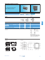
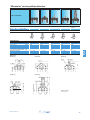
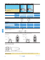
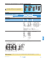
Pneumatics products
Logic elements,
Position / Detectors
Electro-pneumatic valves
Switching
Control systems
Directional control
www.crouzet.com
For over 50 years, Crouzet, has established a reputation for
providing micro-control products, micro-motors and position
sensors. Read on to discover Crouzet's complete offer of
Pneumatic products for industrial and explosive atmospheres.
Always one step ahead of market trends and customer
requirements, Crouzet is continually developing its range of both
standard and customised automation components and solutions
to cover all the latest commercial and industrial applications
and meet the needs expressed by manufacturers of automated
equipment and machinery.
Throughout the world, Crouzet the adaptation specialist provides
you with technical and industrial expertise to ensure seamless
integration, whatever the equipment environment or operating
requirements of the machine.
Crouzet belongs to Custom Sensors & Technologies (CST) which is made up of the leading brands of Kavlico, Crydom
as well as the former divisions of BEI Technologies, including Newall and Systron Donner. In addition to the Microcontrol products in this brochure, CST also offers an extensive range of products and solutions in detection, control and
motorisation. The result? Even better service and technical choice for our customers.
Eco-design is central to the company's "Offer Creation Process", the aim of which is to design products and services that
correspond as closely as possible to customers' requirements and reduce their environmental impact throughout their life
cycle.
Customer satisfaction will always be our prime objective.
To this end, we rely on standards ISO 9001 and ISO14001 to ensure that our design, industrialisation, manufacturing and
commercialisation processes correspond to our customers' requirements.
All Crouzet products are fully
compliant with the RoHS directive
2
www.crouzet.com
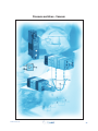
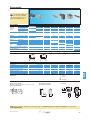
Expertise - for all your applications
Crouzet's Pneumatic expertise
provides you with an offer to meet all your automation system requirements, including systems for explosive
atmospheres.
The quality of the Pneumatic components is based on a rigorous organisation which meets all current European
and international directives, standards and approvals.
All our products are fully compliant with the RoHS directive and embody an eco-design concept.
The Pneumatic offer is the result of the implementation of Crouzet applications and expertise:
3 Listening to and analysing your requirements
3 Expertise in the associated applications: mechanical, electronic, sensors, etc.
3 Prototyping and industrialisation
3 Tests
3 Standardisation and certification (IEC, EN, UL-CSA, ATEX, etc.)
3 Equipment which is responsive and effective
3 International logistics and after sales support.
Crouzet has developed broad expertise in ensuring that your specific needs are taken into account. Thanks
to this expertise, we are continuously developing our standard products to create solutions tailored to your
requirements.
Some relevant areas
Water treatment, chemical factories, silos, gas storage, ports, refineries, paper industry,
paint factories, vehicles (if used in ATEX conditions), etc.
www.crouzet.com
3
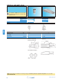
Pneumatic offer for use in industrial and explosive atmospheres
This
guide has been designed to help you quickly identify the appropriate products for your
requirements.Most of our pneumatic components are available in a standard range and a range for use
in explosive atmospheres (ATEX): this information is given in the right-hand column on each page.
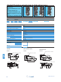
Industrial range
The standard range of pneumatic components is designed to meet
requirements for industrial applications.
The operating characteristics (pressure, flow rate, service life, etc.)
have been optimised to best meet these needs.
Range for use in explosive atmospheres
The range for use in explosive atmospheres has been developed
specifically for applications requiring compliance with European
Directive 94/9/EC, the full details of which can be found on pages
30 and 31 of this guide.
The user is responsible for ensuring the compliance of his
installations. All new installations must be compliant, and
replacements in the event of breakdown or maintenance must
comply with this directive.
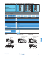
Characteristics of our ATEX components
3 ATEX products are specifically marked in accordance with the
latest versions of harmonised standards
3 Every product is supplied with a guide specifying the usage
restrictions in explosive atmospheres
3 A copy of the approval certificate can be provided if requested
at the time of order
3 The order entry must state the usage conditions Crouzet states
the usage restrictions on acknowledgements of receipt of order,
delivery notes and invoices
Crouzet has produced a separate catalogue for Pneumatic
products for use in explosive atmospheres.
This catalogue gives details of the entire Crouzet range of ATEX
pneumatic products along with associated standards, certifications,
directives, markings and order conditions.
4
www.crouzet.com
ATEX Directive 94/9/EC: general information
Principles of Directive 94/9/EC:
Application since 30 June 2003:
The directive aims to harmonise the legislation of European
Union member states in order to ensure free circulation of
equipment intended for use in explosive atmospheres (gas and
dust).
Manufacturers must offer products, which comply with Directive
94/9/EC and must have a Quality Control System that has been
approved by a notified body.
Since 1 July 2003, this directive has applied to electrical, mechanical, hydraulic and pneumatic products.
It concerns the assessment of protective devices and systems
(manufacturers) as well as the design (design office), installation (installers, panel-builders) and maintenance (maintenance
depts) of installations.
Definition of an explosive atmosphere:
An explosive atmosphere is defined as a mixture of flammable
substances (in the form of gas, vapour, mist or dust) with air
under atmospheric conditions in which, after ignition, combustion
spreads throughout the entire unburned mixture.
Sparks
Heat source
Users are responsible for using equipment correctly according
to the zones they have defined within their installations based
on the potential risks. Existing installations must be brought into
conformity with the ATEX Directive before 30 June 2006. All
new products commissioned must comply with Directive 94/9/
EC. In the event of breakdown, installed equipment that cannot
be repaired must be replaced with equipment complying with
Directive 94/9/EC
Classification:
Potentially explosive environments are classified by zone in
compliance with Directive 1999/92/EC. This directive is aimed
at users. It details the minimum requirements for increasing
protection of the health and safety of workers exposed to
explosive atmospheres.
ATEX Directive 94/9/EC defines categories of equipment and
protection systems, which can be used in the corresponding
zones.
Categories M1 and M2 relate to mines (group I)
Categories 1, 2 and 3 relate to other locations (group II)
often referred to as "Surface industries"
Documents and recommendations/products:
ATEX-certified products must be supplied with an EC declaration
of conformity and a user manual.
Oxidiser
Oxygen (air contains
21% oxygen)
Fuel
Flammable substances in the
form of gas, vapour, mist, dust
At the time of sale, the sales representatives must check the zone
in which the product is to be used. On the order, the customer
must inform the manufacturer of the conditions of use.
Manufacturers and distributors must ensure that their sales of
ATEX products are traceable (so that customers who have been
sold an ATEX product can be located in relation to the product's
date of manufacture).
In the case of an assembly, the product with the lowest certification level determines the level of the whole assembly.
Some relevant areas:
Silos
Ports
Water treatment
Refineries
Paper industry
Gas storage
Paint factories
Vehicles
(if used in ATEX conditions)
www.crouzet.com
Chemical factories
5
Equipment definition:
Equipment for surface industry - Group II
Zone
0
20
1
21
2
22
Type of atmosphere
G = Gas, D = Dust
G
D
G
D
G
D
Presence of Explosive
atmosphere
Continuous presence
(or for long periods, i.e. more than
1000 hours per year)
Intermittent presence
(or occasional, i.e. 10 to 1000
hours per year)
Fleeting presence
(or rare, i.e. 1 to 10 hours per
year)
1
2
3
Category of equipment
that can be used
as per 94/9/EC dated 23/03/94
Marking example:
Certified products must incorporate marking specific to Directive 94/9/EC, such as:
Crouzet Automatismes SAS
2 rue du Docteur Abel, 26902 Valence, FRANCE
Type: 81513530
Serial no:
Year of construction
CE 0081
II 1 G
Ex ia II C T6
LCIE 02 ATEX 6121 X
Max. amb. T: +50°C
Explanation of the marking example:
The CE marking along with the identification number of
the notified body responsible for monitoring the QCS
(0081 = LCIE).
CE 0081
II 1 G
symbol indicating that this product can be used
The
in an explosive atmosphere followed by the equipment
group (II = Surface Industries), the category
(1 = continuous presence; 2 = intermittent presence;
3 = fleeting presence), and the type of explosive
atmosphere G = Gas, D = Dust.
In affixing this CE marking, the manufacturer declares that the
product has been manufactured in complete conformity with the
requirements of all the relevant directives.
Next line of the marking specified by the harmonised standards:
Ex
The CE-Type Examination Certificate reference (if appropriate).
LCIE 02 ATEX 6121 X
Max. amb. T: +50°C
The ambient operating temperature range.
In the event of use in an explosive atmosphere caused by dust,
the following items are added to the marking:
The surface limit temperature T° C for use in an explosive
atmosphere caused by dust.
The IP rating (only for dust)
ia II C T6 X
Reference to the operating instructions
for the product
Temperature Class corresponding to a max.
surface temperature of 85°C
Subdivision IIC: including hydrogen acetylene
in particular, carbon bisulfur
Protection method used: intrinsic safety
Symbol indicating that the equipment complies with one or more
protection methods
6
www.crouzet.com
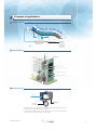
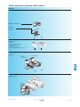
Examples of applications:
Medical
mattress
Microporous
textile
Pressure
zones
Electrical control
Solenoid valves
Air supply
Control console
Textile
machine
Worked yarn
Weaving unit
Process control
Yarn processing modules
To yarn processing module
Pneumatic solenoid valves
Unprocessed yarn
Industrial
valve
Electronic valve
Air supply
Exhaust
Open/close
flow control
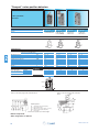
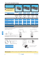
Pneumatic actuators for quarter-turn or proportional taps and valves allow open/close
commands and flow rate changes to be automated.
The pneumatic actuating cylinder is operated by means of an air distributor valve built
into the valve body and controlled by a solenoid valve.
www.crouzet.com
7
Marking
control system
Semi-automatic
Automatic
8
resin filling system, with anti-drip control
assembly system
www.crouzet.com
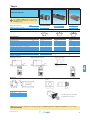
Particular realizations
Component
Solenoid
Valves
on manifold mastered
valves on manifold
System
for inflating
modules on manifold
For others configurations, consult us
www.crouzet.com
9
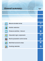
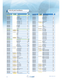
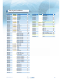
General summary
Pages
Manual actuated valves
11
Position detectors
21
Pressure switches - Vacuum
35
Pneumatic logic components
41
Electro-pneumatic control valves
57
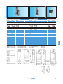
Multi-fluid solenoid valves
69
Teaching materials
72
Manual actuated valves
www.crouzet.com
11
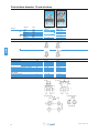
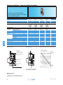
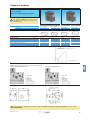
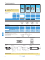
Push buttons diameter 12 and actuators
Features
Version
NC
N0
Actuator
color
black
red
black/red
black
red
black/red
Valve
color
black
black
black
grey
grey
grey
Push button
round
81 735 511
81 735 512
81 735 011
-
Push button
double round
81 733 511
-
2➞8
2.7
200
2➞8
2.7
200
Symbol
NC
1
NO
Characteristics
Operating pressure
Orifice diameter
Flow at 6 bars
NC : black
NO : grey
Operating forces (depending on actuator)
Effective travel
Fluid: dry or lubricated air
Push-in connectors for semi-rigid tubing
(NFE 49100)
Operating temperature
Mechanical life
Weight
bar
mm
Nl/mn.
●
●
Valves
●
8 ➞ 18
1
N
mm
8 ➞ 18
1
mm
Ø4
Ø4
°C
operations
g
-5 ➞ +50
1.5 x 10⁶
35
-5 ➞ +50
1.5 x 10⁶
40
●
●
Dimensions
81 735
Threaded barrel
12
81 733
2 threaded barrels
www.crouzet.com
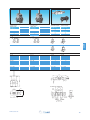
3-position lever
manual return
81 716 511
81 716 512
-
3-position lever
spring return
81 715 511
81 715 512
-
Horizontal outputs
Vertical outputs
81 280 510
81 280 010
-
81 281 510
81 281 010
-
1
2➞8
2.7
200
2➞8
2.7
200
2➞8
2.7
200
●
●
●
●
8 ➞ 18
1
8 ➞ 18
1
●
2➞8
2.7
200
-
1
1
-
●
-
Ø4
Ø4
Ø4
Ø4
-5 ➞ +50
1.5 x 10⁶
65
-5 ➞ +50
1.5 x 10⁶
65
-5 ➞ +50
1.5 x 10⁶
14
-5 ➞ +50
1.5 x 10⁶
14
81 715 - 81 716
81 280 010 - 81 280 510
Square lever
81 281 010 - 81 281 510
28,5
M3
www.crouzet.com
13
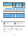
3/2 valves for manual actuators Ø 22 mm
Connection
3/2 valve supplied with screws
89 543 501
Ø4
89 543 701
for fixing the adaptator
Gas 1/8
Valve(s) 3/2 fixed on adaptator
(supplied with adaptator not assembled) Connection Ø 4
Adaptator for 3/2 valve on actuators Ø 22
Version
NC
89 543 101
89 543 201
-
-
-
-
-
-
89 543 105
89 543 005
89 543 305
89 543 205
-
-
-
-
NC + NC
0 ➞ 10
2
90
12.6
-10 ➞ +60
1.5 x 10⁶
NO
NC
NO
NC + NO
0 ➞ 10
2
90
12.6
-10 ➞ +60
1.5 x 10⁶
0 ➞ 10
2
90
12.6
-10 ➞ +60
1.5 x 10⁶
0 ➞ 10
2
90
12.6
-10 ➞ +60
1.5 x 10⁶
0 ➞ 10
2
90
12.6
-10 ➞ +60
1.5 x 10⁶
24 679 702
Symbol
Characteristics
bar
mm
NI/min
N
°C
operations
0 ➞ 10
2
90
12.6
-10 ➞ +60
1.5 x 10⁶
g
50
●
●
50
●
60
Principle of operation
Dimensions
NC version
89 543 001 - 89 543 201
●
●
60
110
-
●
110
40
Ø 22 series
89 543 501 - 89 543 701
60
40,2
Exhaust
1
2
Supply
Output
Holes drilled in panel for actuators Ø 22
Installation
EN 50007
46,5
1
Operating pressure
Orifice diameter
Flow at 4 bars
Control force
Operating temperature in dry air
Life
Non-connectable exhaust
Weight
32
Holes drilled for the (optional)
use of a round lug.
* > 40 Ø 40 push-buttons
* > 45 for lever type rotary switches
14
www.crouzet.com
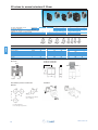
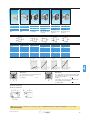
Actuators Ø 22 mm for manually operated valves
Push buttons
Red
Green
Black
2-positions rotary switches
3-positions rotary switches
Function
24 678 129
24 678 128
24 678 127
Flush push
contact
24 678 173
24 678 172
Emergency stop
plastic Ø 40
24 678 171
Emergency stop
Ø 40 mm pushturn
24 678 174
Black symmetrical
actuator
24 678 175
Long lever Black
Symbol
Position
45°
Weight
g
30
45
45°
45
45
24 678 127 - 24 678 128
24 678 171 - 24 678 172
24 678 129
24 678 173
Ø 29
Ø 40
2-positions rotary switches
3-positions rotary switches
Function
24 678 180
RONIS key 455
removable in
position 0
24 678 176
Black symmetrical actuator
24 678 178
Black symmetrical actuator
with return
1
34,5
13,5
Dimensions
45
24 678 177
Long lever
Black
24 678 179
Black Long
lever, spring to
center
24 678 182
RONIS key
455 remov.
in pos. 0
3 positions with
spring to center
24 678 181
RONIS key
455 removable
in position 0
3 fixed
positions
Symbol
Position
45°
Weight
Dimensions
70
2 x 45°
2 x 45°
2 x 45°
2 x 45°
2 x 45°
2 x 90°
45
45
16
45
70
70
24 678 174 - 24 678 176
24 678 175 - 24 678 177
24 678 180 - 24 678 181
24 678 178
24 678 179
24 678 182
Ø 30
38,3
Ø 29
29
27
23
27
27,3
www.crouzet.com
15
the
rms to tive
o
f
n
o
C
irec
nery D
i
h
c
a
M
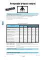
Definition
(conforming to EN 574 +A1)
A pneumatic 2-hand control device is used with dangerous machinery and requires the simultaneous use of both
hands to trigger and maintain machine operation. Such a device must be located outside the dangerous zone, so
that the operator cannot enter this zone before the machine has come to a complete standstill.
A pneumatic 2-hand control device is composed of 2 parts :
■
2 manual pushbuttons which require the simultaneous use of both hands.
■
A pneumatic relay.
1
Types of 2-hand control devices
Type
Requirements
I
III
II
A
B
C
Use of both hands (simultaneous actuation)
●
●
●
●
●
Relationship between input signals and
output signal
●
●
●
●
●
Cessation of the output signal
●
●
●
●
●
Prevention of accidental operation
●
●
●
●
●
Prevention of defeat
●
●
●
●
●
●
●
●
●
●
●
●
Reinitiation of the output signal
Synchronous actuation
Use of category 1 (EN 954-1)
●
●
Use of category 3 (EN 954-1)
●
●
Use of category 4 (EN 954-1)
●
Category 1 (EN ISO 13849) :
the system should use well tried components and principles.
Category 3 (EN ISO 13849) :
the system must be designed so that a single fault will not cause the loss of the
safety function.
Category 4 (EN ISO 13849):
the system must be designed so that an accumulation of faults must not lead to
a loss of the safety function.
Synchronous action
An output signal is only generated if both control actuating devices are actuated within 500 ms.
Resetting the output signal
The release of a single control device interrupts the output signal, but a reset is only possible once both control
devices have been released.
16
www.crouzet.com
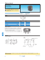
Pneumatic relay for two-hand control
■
100% pneumatic
■ Complies
with Machinery Directive and the
standard EN 574 +A1
■
CE Certification type-IIIA and IIIB
81 580 101
III A
Pneumatic relay for two-hand control
EN 574 +A1 classification
81 580 202
III B
Symbol
1
3
1
2
Characteristics
Operating pressure
Orifice diameter
Max. delay between input signals
Connection
Operating temperature
Mechanical life
Weight
Principle of operation
2➞8
2.5
0.2 max.
Sub-base 81 532 001
-5 ➞ +50
°C
107
operations
90
g
Connections (Typical application with double-acting cylinder)
81 580 101
81 580 101
2➞8
2.5
0.2 max.
Semi-rigid tubing Ø 4 (NFE 49100)
-5 ➞ +50
107
320
bar
mm
s
1
81 580 202
1
81 580 101
81 580 202
Components follow current standards
To obtain an output signal it is necessary
to give simultaneous input signals 'a' and
'b' with a max. delay of 0.45. The output
signal 's' is lost if one or both of the
inputs are removed.
Dimensions
81 580 202
34,5
64
125,7
10,5
15
25
76
23
32
81 580 101
Sb
Sa
Pb
Pa
Sb
Sb
Pb
Pb
Mounted on sub-base 81 532 001
(See page 55 of Pneumatic catalogue)
32
M4
24
www.crouzet.com
2 x M3
Depth 10
17
Two-hand pneumatic safety start module
■
Conforms to the Machinery Directive and
standard EN 574
■
Including pneumatic relay to classification IIIA
or IIIB depending on version
Two-hand pneumatic safety start module
Pneumatic relay (to EN 574)
81 580 504
Type III A
81 580 503
Type III B
S
S
P
P
Symbol
Characteristics
1
Operating pressure
bar
Orifice diameter
mm
Max. delay between input signals
s
Connection
Operating temperature
°C
Mechanical life
operations
Weight
g
Connections (Typical application with double-acting cylinder)
81 580 504
P
2➞8
2.5
0.2 max.
Semi-rigid tubing Ø 4 (NFE 49100)
-5 ➞ +50
1.5 x 10⁶
1000
S
81 580 503
P
81 580 504
2➞8
2.5
0.2 max.
Semi-rigid tubing Ø 4 (NFE 49100)
-5 ➞ +50
1.5 x 10⁶
1410
1
S
81 580 503
Components follow current standards
Dimensions
81 580 503 - 81 580 504
Supply via 4 mm
push-in fitting
Output via 4 mm
push-in fitting
Fixing viewed from below
18
www.crouzet.com
Pneumatic impulse counters
■
4, 5, 6 digits with or without reset
■
With or without pre-selection
Totalizer
Preselection counter
Version
99 766 001
6 digits no reset
to zero
99 766 002
4 digits with
manual zero reset
89 538 201
5 digits with
manual or pneumatic zero
reset
2➞8
> 0.3
> 1.4
2➞8
> 0.3
> 1.4
0 ➞ +60
150
0 ➞ +60
150
2➞8
> 0.15
> 0.8
2
150
2➞8
Symbol
1
Characteristics
Supply pressure
Pressure to break
Pressure to make
Reset :
Minimum pressure
Reset time
Circuit pressure
bar
Signal emitted when preset is reached
Operating temperature
Weight
-
bar
bar
bar
bar
ms
°C
g
●
0 ➞ +60
136
A - Output signal
P - Supply
Y - 'Reset to zero'
signal
Z - Input signal
Connection
Note : the count pulse must be removed
before the reset pulse is applied. The preset value can be changed during operation
without the counter resetting to zero.
Dimensions
Connectors for semi-rigid tubing Ø 4 (NFE 49100)
99 766 002
22 x 33,3
14,5
48
5,3
89 538 201
Ø 3.2 f/90°
24
=
2 holes for M3 screws
=
Ø4
0000
=
Ø 3,2 F/90
41,5
2
60,6
=
3
99 766 001
=
Ø4
0 0 0000
=
Ø 3,2 F/90
41,5
www.crouzet.com
=
24
=
23
=
48
=
=
37
=
M3
41,5
19
Indicators and pedal valves
■
Ergonomics
Also available in ATEX version for use in potentially explosive atmospheres in accordance with
94/9/EC Directive
Pneumatic indicators Ø 22
84
84
84
84
Red
Green
Yellow
Blue
150
150
150
150
Pedal valve - Version NC
201
202
203
204
-
81 999 501
Symbol
1
Characteristics
Operating pressure
Push-in connection for semi-rigid tubing
(NFE 49100)
Operating temperature
Mechanical life
Weight
Dimensions
bar
2➞8
mm
Ø4
Ø4
-
°C
operations
g
-5 ➞ +50
107
34
-5 ➞ +50
1.5 x 10⁶
290
84 150 201 - 84 150 202
84 150 203 - 84 150 204
81 999 501
White tube
Input
Output
Red tube
Holes drilled for indicators
ATEX version products are available in the following catologues: Pneumatic products for explosive atmospheres or on our website
www.crouzet.com
20
www.crouzet.com
Position detectors
www.crouzet.com
21
Pressure decay sensor
■
100 % pneumatic
Also available in ATEX version for use in potentially explosive atmospheres in accordance with
94/9/EC Directive
Pressure decay sensor
81 504 025
Symbol
Characteristics
Operating pressure
Flow at 6 bars
Tripping point
with 6 bar supply
Connection
Operating temperature
Mechanical life
Weight
Connections
bar
NI/min
2➞8
200
b
0.3
Sub-base page 54-55
°C
-5 ➞ +50
107
operations
25
g
Without flow restrictor
Signal
when
cylinder
is in
2
Principle of operation
Fitted in-line between the cylinder and the
control valve, the sensor will give an output
when the pressure in this line is exhausted
and the cylinder is at end of stroke.
With flow restrictor
Signal
when
cylinder
is out
Evolution of pressure within a double-acting cylinder
Pressure
in the cylinder
Circuit
pressure
For the correct usage of sensors on a falling
pressure, it is recommended that the practical
cylinder load is limited to 60% of the theoretical force.
Working pressure
Operation of
the sensor on a
fall in pressure
Pressure
difference
Exhaust
pressure
Cylinder
response time
Cylinder travel
time
Control valve Starting point
changeover of cylinder
Time
End of stroke
Dimensions
81 504 025
ATEX version products are available in the following catologues: Pneumatic products for explosive atmospheres or on our website
www.crouzet.com
22
www.crouzet.com
Low force position detector
100 % pneumatic
Conforme à la nore DIN 41365 Forme A
Faible effort d'actionnement < 50 g à 6 bars
Pas de consommation permanente d'air
comprimé
■
■
■
■
Also available in ATEX version for use in potentially explosive atmospheres in accordance with
94/9/EC Directive
NO
NC
Function
81 290 501
-
81 290 001
2
3➞8
100
< 0,5
2
3➞8
100
< 0,5
Symbol
Characteristics
Orifice diameter mm
Operating pressure
Flow at 4 bars
Activation force at 6 bars
Permissible fluids (air / inert gas)
Max/min
of fluid
temperatures operating
storage
Mechanical life at 6 bars
Response
on activation
time
on release
Barb connection for semi-rigid tubing
Weight
Principle of operation NC
bar
NI/min
N
●
●
-10 ➞ +50
-10 ➞ +60
-40 ➞ +70
107
15
15
2.7 x 4
8.5
°C
°C
°C
operation
ms
ms
g
-10 ➞ +50
-10 ➞ +60
-40 ➞ +70
107
15
15
2.7 x 4
8.5
Desactivated
2
Activated
S
(2)
(1)
Operation accessories
Unless otherwise requested, flat and roller-ended levers
are supplied loose.
161 A
flat R 25.4
70 507 524
161 E
with roller R 24.1
70 507 529
Dimensions
161 A
R 25.4
161 E
R 24.1
±0,2
R
3.4
R
8
Ø4.8
±0.2
4.3
2.4
16
16.5
0.5
14.7
3.2
10.3
+0.15
3.4
5.8
3+0.05
5
20
11.8
3.8
±0,2
6.3
Position
repos
Rest
point
travel
2.5 Total
Course
totale
30
+0.15
Ø3+0.05
Tripping d'action
point
Position
DIN 41635 Form A
12.95
10.7
22.2
3.9
ATEX version products are available in the following catologues: Pneumatic products for explosive atmospheres or on our website
www.crouzet.com
www.crouzet.com
23
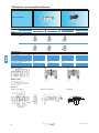
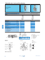
“Microvalve” series position detectors
■
100 % pneumatic
81 280
Version
81 281
81 280 010
81 280 510
Horizontal output
81 281 010
81 281 510
Vertical output
81 283 510
Rear connection by screw
bar
mm
NI/min
N
mm
2→8
2.7
200
15
1
2→8
2.7
200
15
1
2→8
mm
Ø4
Ø4
Ø4
°C
operat.
g
-5 ➞ +50
5 x 10⁶
14
-5 ➞ +50
5 x 10⁶
14
-5 ➞ +50
5 x 10⁶
20
NO
NC
Features
Symbol
NO
NC
Characteristics
138
15
1
NO
PR
NC
PRT
PA
Principle of operation
PFC
Actuation positions :
PFC
PA
PRT
PR
:
:
:
:
End of travel position
Operating position (max output kV)
Release position (max. exhaust kV)
Rest position
Dimensions
81 281 010 - 81 281 510
81 280 010 - 81 280 510
81 283 510
o
5,2
2
Operating pressure
Orifice diameter
Flow at 6 bars
Operating force at 6 bars
Effective travel
Push-in connection for
semi-rigid tubing (NFE 49100)
Operating temperature
Mechanical life
Weight
11,5 11,5
24
www.crouzet.com
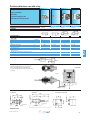
“Microvalve” series position detectors
■
100 % pneumatic
Short lever
With ball
Roller trip
With roller
81 281 502
81 281 504
81 281 508
81 281 509
Threaded barrel Ø 16
Plunger
81 737 501
bar
mm
NI/min
N
mm
2→8
2.7
200
15
1
2→8
2.7
200
15
1
2→8
2.7
200
15
1
2→8
2.7
200
15
1
2→8
2.7
200
25
1
mm
Ø4
Ø4
Ø4
Ø4
Ø4
°C
operat.
g
-5 ➞ +50
5 x 10⁶
16
-5 ➞ +50
5 x 10⁶
18
-5 ➞ +50
5 x 10⁶
18
-5 ➞ +50
5 x 10⁶
18
-5 ➞ +50
5 x 10⁶
90
Features
Version
NC
Vertical output
Symbol
Characteristics
Operating pressure
Orifice diameter
Flow at 6 bars
Operating force at 6 bars
Effective travel
Push-in connection for
semi-rigid tubing (NFE 49100)
Operating temperature
Mechanical life
Weight
2
Dimensions
81 281 502
81 281 504
81 281 508
PR
PR
PR
Ball Ø 9
PR
Actuation positions :
PR
2 nuts 21 mm across flat
18 mm
Max. fixing capacity
81 737 501
PR
81 281 509
www.crouzet.com
PR : Rest position
25
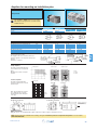
"Miniature" series position detectors
■
100 % pneumatic
■
All metal
Part numbers
Version
Push-in connection for semi-rigid tubing
(NFE 49100)
Ø 4 silenced exhaust
M5 connectable exhaust
Ø 4 connectable exhaust *
Ø 6 connectable exhaust *
Ø 4 silenced exhaust
Ø 6 silenced exhaust
NC
NO
Control
81 921 501
Simple plunger
81 921 701
Lever with plastic
roller
81 921 702
Lever with roller
bearing
81 921 707
Lever with one-way
trip plastic roller
Symbol
NC
NC
Characteristics
Operating pressure
Orifice diameter
Flow at 6 bars
Actuation force at 6 bars
Circuit function : NC
Circuit function: NO
Connectable exhaust
Operating temperature
Mechanical life
Weight
bar
mm
NI/min
N
°C
operations
g
0.1 → 8
2.7
200
18
0.1 → 8
2.7
200
18
0.1 → 8
2.7
200
18
●
●
●
●
-
-
-
-5 ➞ +50
≥107
62
-5 ➞ +50
≥107
75
Principle of operation
NC
0.1 → 8
2.7
200
18
-
-5 ➞ +50
≥107
80
-5 ➞ +50
≥107
77
Actuation travel
NO
Vertical attack
Simple plunger
Exhaust
Actuation positions :
PRT =
PA =
PO =
PR =
Poppet
PFC =
2
NC
PA : Operating position (max output kV)
PFC : End of travel position
PO : Mid-position closed
(no exhaust, no outlet)
PRT : Release position
(max exhaust kV)
PR : Rest position
Dimensions
81 921 501
*
81 921 701 - 81 921 702
81 921 707
with barb for tube Ø 2.7 x 4
Material: body zamak
26
www.crouzet.com
81 921 806
Lever with plastic
roller
81 921 714
Lever with roller
bearing
NC
0.1 → 8
2.7
200
18
81 921 719
81 921 911
81 921 901
Lever with plastic
roller
NC
0.1 → 8
2.7
200
18
81 921 717
81 921 912
81 921 902
Lever with roller
bearing
NO
0.1 → 8
2.7
200
18
2
0.1 → 8
2.7
200
18
●
●
●
●
-
-
●
●
-5 ➞ +50
≥107
75
-5 ➞ +50
≥107
80
●
●
-5 ➞ +50
≥107
100
-5 ➞ +50
≥107
100
Horizontal actuating 30° cam (other angles of attack are also possible, 45° even 90°).
With lever
With lever
One-way trip lever
With lever
PA =
PO =
PRT =
PA =
Horizontal actuating 30° cam (other angles of
attack are also possible, 45° even 90°).
81 921 714
PRT =
PR =
PRT =
81 921 717 - 81 921 719
81 921 901 - 81 921 902
81 921 911 - 81 921 912
25,5
44,5
26
81 921 806
PA =
PO =
PR =
PRT =
PA =
PO =
PR =
PFC =
PO =
36
Material: body zamak
Other configuration on demand
www.crouzet.com
27
"Compact” series position detectors
■
100 % pneumatic
■
All metal
Part numbers
Features
Direct acting
81 922 401
Roller plunger with
unthreaded barrel
Version
Rotary actuator
81 922 205
Right-hand rotary
head with roller
lever (CNOMO)
Rotary actuator
81 922 010
Programmable
rotary head
without lever
Rotary actuator
81 922 210
Programmable
rotary head
without lever
Symbol
Characteristics
BSP
push-in for semi-rigid tubing
mm
(NFE 49100)
Operating pressure
bar
Bore diameter
mm
Flow at 6 bars
Nm3/h
Activation force at 6 bars
daN
Circuit function: NC
Mechanical life
operations
Silenced or connectable (1/8) exhaust
Operating temperature
°C
Weight
g
-
Connection
Ø4
-
●
> 107
> 107
●
●
> 107
●
●
-5 ➞ +50
150
0.1 → 8
3
200
2.5
●
●
> 107
-
0.1 → 8
3
200
2.5
0.1 → 8
3
200
2.5
0.1 → 8
3
200
2.5
1/8
Ø4
●
-5 ➞ +50
193
-5 ➞ +50
175
-5 ➞ +50
175
●
●
●
●
●
●
●
●
●
●
●
●
●
●
●
Accessories
79
79
79
79
79
plastic
bearing
Lever with adjustable
plastic
roller
bearing
Adjustable steel rod lever
Lever with roller
452
452
452
452
452
103
104
123
124
133
-
Principle of operation
Exhaust
2
S
Poppet
1
Vertical attack
Horizontal attack
Detectors with roller plunger with unthreaded barrel.
Detectors with roller plunger with unthreaded
barrel.
PRT
PO
PA
Line of attack
PFC
PA
PO
PRT
Actuation positions :
PR
2
-
1/8
PA
PFC
PO
PRT
PR
:
:
:
:
:
Operating position (max output kV)
End of travel position
Mid-position closed (no exhaust, no outlet)
Release position (max exhaust kV)
Rest position
The detectors 81 922 010 and 81 922 210 can operate to both left and right.
Material: body zamak
Other configuration on demand
28
www.crouzet.com
Rotary actuator
Detectors with levers
81 922 - 81 922 0 - 81 922 2
2
Dimensions
81 922 401
79 452 123 - 79 452 124
22
+ 0,1
-
32,5*
3,4
Ø 11
79 452 133
37
42,5*
19
R 120 max.
96
R = 47
28,5
12,5
23,5
29,7
3
Ø 11,6
= =
+
20 - 0,1
16
31
81 922 205 - 81 922 0 - 81 922 2
79 452 103 - 79 452 104
36*
18
49
Ø 18
21,5
25*
www.crouzet.com
29
"Adjustable stop" series position detectors
■
100 % pneumatic
■
All metal
Part numbers
81 923 001
Barb for tube 2.7 x 4
81 921 505
Push-in connector for tube Ø 4
bar
mm
NI/min
N
0,1 → 8
2
130
16
0,1 → 8
2,7
200
21
daN
1000
●
●
°C
operations
g
-5 ➞ +50
≥107
27
-5 ➞ +50
≥107
90
mm
mm
0,4
0
0,7
0
mm
0,9
1
mm
1,5
1,5
mm
3
3
Push-in connection for semi-rigid tubing (NFE 49100)
Symbol
Characteristics
2
Operating pressure
Orifice diameter
Flow at 6 bars
Actuation force at 6 bars
Circuit function: NC
Max. load: without shock
Will stop a 63 mm Ø cylinder : 6 bar supply
Operating temperature
Mechanical life
Weight
Actuation positions
PA : Operating position (max output kV)
PFC : End of travel position
PO : Mid-point closed
(no exhaust, no outlet)
PRT : Release position
(max. exhaust kV)
PR : Rest position
●
●
1000
Principle of operation
Black barb
Exhaust
Poppet
Versions
PO
With barb
0.9
Ø4
1
Values in mm
PA
0.4
0.7
PFC
0
0
PRT
1.5
1.5
PR
3
3
Actuation positions :
PA : Operating position (max output kV)
PFC : End of travel position
PO : Mid-position closed
(no exhaust, no outlet)
PRT : Release position
(max exhaust kV)
PR : Rest position
Dimensions
81 923 001
81 921 505
Fixing
This should be as
close as possible to the
plunger
17 Across
17 Across
fl12,5
flat
flat
M12x1
Material: body zamak
30
www.crouzet.com
Position detectors use with relay
■
100 % pneumatic
■
All metal
■
Low force operation <N 1
■
Very low force Version 30 mN
References
Version
81 512 201
with ball
81 512 401
with wire
81 502 435
Positive
81 505 435
Negative
Symbole
Characteristics
Push-in connection for semi-rigid tubing
(NFE 49100)
Life at 6 bars
Actuation force at 6 bars
Fluid used: that delivered by the leak sensor
relay..
Operating temperature
Weight
mm
Operating pressure
Sensor consumption for relay
supply at 6 bar
The distance between relay and sensor must
be less than 15 m for a tube Ø 2.7 x 4 mm
Connection - sub-base see pages 54/55
Mechanical life
Ø4
Ø4
operations
N
107
0,8
107
0,025
●
●
°C
g
-5 ➞ +50
24,5
-5 ➞ +50
23,5
-5 ➞ +50
35
-5 ➞ +50
35
bar
2→8
2→8
Nl/
5
5
●
●
≥10 7
operations
2
●
●
≥10 7
Connection
Principle of operation
Supplied at industrial pressure, the relay produces a permanent bleed at its input port.
A sensor shutting off this bleed causes the relay
to switch.
81 502 435
Exhaust
Sub-base (see page
54/55)
Dimensions
81 512 201
Connector
Ø4
81 512 401
81 502 435 - 81 505 435
17 mm Across
flat
17 mm Across
flat
Connector Ø 4
Material: brass
www.crouzet.com
31
Position detectors
■
100 % pneumatic
■
All metal
■
Gap, proximity, paddle
Part numbers
81 371 401
de proximité
Detector
81 372 201
gap
81 372 401
gap
81 372 901
with palette
Symbol
S
P
P
S
Characteristics
2
Detection distance
18 mm gap sensor
Supply pressure
Minimum output pressure
Unlimited life (static component)
Operating temperature
Consumption at supply
0.5 b
pressure of:
2.5 b
Barb connection for semi-rigid tubing
(NFE 49100)
Operating
nozzle
pressure
d. detection 200 mm
sensor
d. detection 100 mm
Flow
nozzle at 2 bars
sensor at 2 bars
at 2 bars
at 6 bars
Sensor consumption for relay supply
at 6 bars
Weight
Principle of operation
mm
6 ➞ 10
18
100
bar
mbar
0.5 → 2.5
1
0.5 → 2.5
5
0.5 → 2.5
5
°C
NI/h
NI/h
- 20 ➞ +70
800
2500
- 20 ➞ +70
70
2200
- 20 ➞ +70
100
700
mm
Ø 2.7 x 4
Ø 2.7 x 4
Ø 2.7 x 4
●
-
bar
bar
NI/h
NI/h
N
N
-
36
9
Black barb
●
-
-
NI/min
g
●
Ø 2.7 x 4
-
2→8
2→8
1→4
320
320
0.03
0.09
-
5
63
14
Black barb
Black barb
10 max.
Supply
Used
Connection
Black barb
Black barb
Encombrements
81 371 401
81 371 201
17
Across
flat
32
81 372 401
17 Across
flat
81 372 901
17 Across
flat
www.crouzet.com
Ampliers for mounting on installation plan
■
Gap sensor
Also available in ATEX version for use in potentially explosive atmospheres in accordance with
94/9/EC Directive
Part numbers
Simple amplifiers (for 81 372 201/401)
Sensitive amplifiers (for 81 371 401)
Version
81 502 230
positive
81 505 230
negative
81 502 320
positive
81 505 320
negative
10 → 20
2→8
2.5
5
800
-5 ➞ +50
3 x 10 6
150
10 → 20
2→8
2.5
5
800
-5 ➞ +50
3 x 10 6
150
1→4
2→6
2.5
5
800
-5 ➞ +50
3 x 10 6
185
1→4
2→6
2.5
5
800
-5 ➞ +50
3 x 10 6
185
Symbol
Characteristics
Pressure to make
Operating pressure (non-lubricated air)
Orifice diameter
Average consumption at 4 bars
Permissible overload for 1 hour
Operating temperature
Mechanical life
Weight
Connections
Used for gaps up to 25 mm.
The supply to the sensor should be made via a
pressure regulator or one-way flow restrictor (see
page 52
Connection - sub-base
mb
bar
mm
Nl/min
mb
°C
operations
g
Black barb
10 max.
81525101
Principle of operation
Simple amplifiers
An output at normal industrial pressure is delivered on a low pressure
input.
NB: Hysteresis is 20% of the pilot
pressure.
Sensitive amplifiers
An output at normal industrial
pressure is delivered on a very low
pressure input.
Pilot pressure
81527001
Black barb
81 502 230
81 505 230
Positive output
Negative output
1- pilot
2- supply
3- output
Supply
pressure
Pa
Pilot pressure
5
81 502 320
81 505 320
4
3
Note: The specifications are given
for a supply pressure of 6 bars,
and for detection at the mid-point
of the gap.
2
Supply
pressure
Pa
1
0
1
2
3
4
5
6
7
8
Dimensions
81 502 238 - 81 505 231
81 502 322 - 81 505 321
Push-in connection for
semi-rigid tubing
Ø 4 mm (NFE 49100)
Other information
With gap sensors, use an amplifier with negative output if you require a signal on interruption of the jet.
ATEX version products are available in the following catologues: Pneumatic products for explosive atmospheres or on our website
www.crouzet.com
www.crouzet.com
33
2
Amplifier with intégral régulator, positive output
■
Setting Flow
■
Fixing rail 35mm wide
Part numbers
81 510 001
Positive output
Amplifiers with integral regulator
Version
Symbol
Characteristics
2
Pressure to make
Reduced pressure supplied at port 8
Flow through port 8
Consumption of amplifier only
Permissible overload for 1 hour
Operating temperature
Mechanical life
Weight
Detectors (see page 28)
mb
bar
Nm3/h
NI/h
mb
°C
operations
g
0.5 → 1.5
0.5 → 2.5
0.1 → 2.5
100 → 200
300
-5 ➞ +50
3 x 10 6
380
Proximity
Ø 12
81 371 401
8
-5 ➞ +50
6
3 x 10
Gap
Ø 18
81 372 201
18
Nominal range
Min. total consumption for detection
(0.5 b regulated pressure)
Max. total consumption for short response
time (2.5 b regulated pressure)
Min. detectable
dimensions
nominal sensing distance
Max. frequency of use
2
Force exerted by the jet on the parts
to be detected
mm
-5 ➞ +50
6
3 x 10
Proximity
Ø 12
81 372 401
100
NI/h
880
140
NI/h
2750
400
920
mm
mm
Hz
Ø3
2
5
Ø 2 - Ø 1.5
5
Ø 7 - Ø 6.5
5
N
0.02 → 0.7
0.01 → 0.03
0.1
-
Connection
To use with detectors page 32
Principle of operation
pilot pressure
Dimensions
This amplifier
is suitable for
providing a supply
to associated
sensors.
Push-in connection for semi-rigid tubing Ø 4 mm (NFE 49100)
Viewed from B
Regulated pressure (bar)
Viewed from A
Adjustable regulator
34
www.crouzet.com
Pressure switches - Vacuum
www.crouzet.com
35
Pressure switches - vacuum (electrical output)
■
■
Conform to the Low Voltage Directive
Can be used without enclosure according to
IEC 664-1 pollution group III
Part numbers
Pressure and vacuum switches
Mounting
81 513 552
DIN rail
81 513 502
DIN rail
81 513 501
DIN rail
81 513 522
DIN rail
Actuators
Manual override
Pressure
with
Pressure
without
Low pressure
without
Vacuum
without
Ø 4 ext.
Ø 4 ext.
Ø 4 ext.
Ø 4 ext.
Symbol
Characteristics
Pneumatic
connection
3
Push-in connection for semi-rigid
mm
tubing (NFE 49100)
Tapped BSP via connector
Protection
IEC 529
Permissible fluid: air, inert gases and liquids
Adjustment of switching pressure (* adjusted to 0.3)
bar
Hysteresis
at 1 bar
bar
at 2 bars
bar
at 4 bars
bar
at 6 bars
bar
max. 200 mb
max. 250 mb
Pressure to break
Mechanical life (operations)
Contact rating (V resistive)
Wire cross-section
mm2
Operating temperature
°C
Weight
g
Standard electrical contact
UL and cUL approval
Operation
Pressure operated
IP 20
IP 20
IP 20
●
●
2➞8
0.5
0.6
0.8
1
106
5A - 220-230 V
0.75
-10 ➞ +70
48
V4 83 170 4 I W2
MH15213 (R)
2➞8
0.5
0.6
0.8
1
106
5A - 220-230 V
0.75
-10 ➞ +70
46
V4 83 170 4 I W2
MH15213 (R)
Vacuum operated
IP 20
●
0.3 ➞ 1.2 *
●
●
-0.3 ➞ -0.8
-
-
-
106
5A - 220-230 V
0.75
-10 ➞ +70
46
V4 83 170 4 I W2
MH15213 (R)
106
5A - 220-230 V
0.75
-10 ➞ +70
46
V4 83 170 4 I W2
MH15213 (R)
●
Electrical life
(Crouzet microswitch "V4" ref 83 170 4-1-W2)
Number of cycles
Resistive circuit
Inductive circuit
Electrical output
- common
- normally closed contact
- normally open contact
{
L
c __ = 5 ms
R
a cos q = 0.8
Mechanical
life
Adjustment of switching pressure 1 to 8 bars
Standard microswitch
5 A / 220 V
Manual override
Pneumatic indicator
Marking tag
Current
in Amps
Pneumatic signal
For continuous vacuum applications, please consult us.
Other information
On request :
- Microswitch V4 ref. 83 170 0 i W2 high current
- Microswitch V4 ref. 83 170 9 i W2 low current
36
www.crouzet.com
81 513 516
Base mounted
page 4/14
Pressure
without
81 513 510
Base mounted
page 4/14
Pressure
with
81 513 527
Base mounted
page 4/14
Vacuum
without
Ø 4 ext.
-
Ø 4 ext.
-
Ø 4 ext.
-
IP 54
IP 54
IP 54
81 513 533 81 513 523
2 screws M4 2 screws M4
Pressure
without
1/8 BSP
IP 54
Vacuum
without
81 509 080
Base mounted
page 4/14
Pressure
without
81 509 085
Base mounted
page 4/14
Pressure
with
-
-
-1/8 BSP
IP 54
Via sub-base Via sub-base
IP 54
IP 54
●
●
●
●
●
●
●
2➞8
0.5
0.6
0.8
1
106
5A - 220-230 V
0.75
-10 ➞ +70
56
V4 83 170 4 I W2
MH15213 (R)
2➞8
0.5
0.6
0.8
1
106
5A - 220-230 V
0.75
-10 ➞ +70
58
V4 83 170 4 I W2
MH15213 (R)
-0.3 ➞ -0.9
-
2➞8
0.5
0.6
0.8
1
106
5A - 220-230 V
0.75
-10 ➞ +70
65
V4 83 170 4 I W2
MH15213 (R)
-0.3 ➞ -0.8
-
1.4 ± 0.5
0.6 ± 0.2
106
5A - 220-230 V
1.5
-10 ➞ +70
80
83 133 004
1.4 ± 0.5
0.6 ± 0.2
106
5A - 220-230 V
1.5
-10 ➞ +70
80
83 133 004
Electrical connections
81 513 501 - 81 513 502
81 513 522 - 81 513 552
●
106
5A - 220-230 V
0.75
-10 ➞ +70
56
V4 83 170 4 I W2
MH15213 (R)
Dimensions
81 513 552 - 81 513 502
81 513 501 - 81 513 522
●
106
5A - 220-230 V
0.75
-10 ➞ +70
65
V4 83 170 4 I W2
MH15213 (R)
Pressure switch with connector
81 513 516 - 81 513 510
81 513 527
81 516 082
81 513 533
81 513 523
1 - Common
4 - NO contact
2 - NC contact
81 513 510
81 513 516 - 81 513 527
For M4 screws
length 24 mm
81 513 533
81 513 523 - 81 513 533
Pilot signal
Pilot
signal
81 509 080 - 81 509 085
www.crouzet.com
37
3
Adjustable pressure switches (manostats) (pneumatic output)
100 % pneumatic
■
Also available in ATEX version for use in potentially explosive atmospheres in accordance with
94/9/EC Directive
Part numbers (and adjustment ranges)
Adjustment range
50 → 500 mb
0.1 → 2.5 b
2 →8 b
81 505 140
81 505 150
81 505 160
Positive output
10 %
4%
4%
81 502 140
81 502 150
81 502 160
Negative output
10 %
4%
4%
mm
Nl/min
50 → 500 mb
0.1 → 2.5 b
2→8b
2.5
170
60 mb
100 mb
320 mb
2.5
170
60 mb
100 mb
320 mb
50 → 500 mb
0.1 → 2.5 b
2 →8 b
Version
Accuracy
Symbol
Characteristics
Orifice diameter
Flow at 4 bars
Hysteresis
Connection - sub-base pages 54/55
Operating temperature
Mechanical life
Weight
Connections
3
●
°C
operations
g
●
-5 ➞ +50
3 x 10 6
160
-5 ➞ +50
3 x 10 6
160
Example of pressure threshold adjustment
(mini-regulator - manostat)
Principle of operation
The manostats provide an on or off output signal when the input signal reaches a predetermined pressure threshold.
Positive output
Output signal
Negative output
Output signal
Pilot
Hysteresis
Pilot
Hysteresis
Switching
on
Switching
on
Switching off
Switching off
Dimensions
81 502 140 - 81 502 150 - 81 502 160
81 505 140 - 81 505 150 - 81 505 160
Other information Pressure switches with electrical output on request.
ATEX version products are available in the following catologues: Pneumatic products for explosive atmospheres or on our website
www.crouzet.com
38
www.crouzet.com
Adjustable vacuum switches (vacuostat)
■
100 % pneumatic
■
For vacuum -0,1 ➞ -0,9 Bar
Part numbers
81 505 110
Positive output
81 502 110
Negative output
81 508 110
Electrical output
b
Nl/min
mb
- 0.1 ➞ -0.9
170
80
- 0.1 ➞ -0.9
170
80
- 0.1 ➞ -0.9
170
80
°C
operations
g
-5 ➞ +50
3 x 10 6
160
Symbol
Characteristics
Adjustment range
Flow at 6 bars
Hysteresis
Connection - sub-base pages 54/55
Operating temperature
Mechanical life
Weight
Connections
●
●
-5 ➞ +50
3 x 10 6
160
●
-5 ➞ +50
3 x 10 6
180
Example of use:
Vacuum handling (vacuum generator,
vacuum pad, vacuostats).
3
Principle of operation
Vacuostats provide an on or off output signal when the input signal reaches a predetermined pressure threshold.
Positive output
Negative output
Output signal
Output signal
Switching off
Switching
on
Switching off
Switching
on
Hysteresis
Vacuum
Dimensions
81 502 110 - 81 505 110
www.crouzet.com
Hysteresis
Vacuum
Vacuum
Vacuum
81 508 110
39
Vacuum handling components
■
Sur le principe du Venturi
■
Facilement raccordable
Also available in ATEX version for use in potentially explosive atmospheres in accordance with
94/9/EC Directive
Part numbers
81 535 301
Sub-base mounting
Vacuum generators
81 545 001
Plug-in
81 545 005
Plug-in
Characteristics
Push-in connectors for
semi-rigid tubing
(NFE 49100)
Operating pressure
Vacuum pad material
Weight
Male/Female/Female (MFF)
Female/Female/
Female (FFF)
bar
-
-
2→8
Ø 6 mm
2→8
-
g
-
Ø 4 mm
-
2→8
-
80
-
13
25
Detection of the pressure decrease can be achieved by the
use of manostats (see pages 38/39)
Vacuum (mb)
Suction flow
Vacuum
(mb)
Vacuum (mb)
Suction flow
Vacuum (mb)
Suction flow
Vacuum
(mb)
Vacuum
(mb)
Flow
Flow
Flow
3
Supply pressure (bar)
Dimensions
81 535 301
Supply pressure (bar)
Supply pressure (bar)
81 545 001
Sub-base mounting 81 531… and 81 532…
Plug-in ferrule for push-in connector
Ø 4 mm
24
2 push-in connectors
Ø 4 mm
29
11
40
81 545 005
30,7
Ø 4,5
15,5
40
3 push-in connectors
Ø 6 mm
29 ±0,1
11
10,7
14,5 ±0,1
ATEX version products are available in the following catologues: Pneumatic products for explosive atmospheres or on our website
www.crouzet.com
40
www.crouzet.com
Pneumatic logic components
www.crouzet.com
41
General characteristics
Operating fluid
- Compressed air or inert gas.
flow graphs
Conditions of use
- Operating pressure 2 at 8 bars (except for special conditions).
- Fluid: Filtered air to 50 microns - non lubricated.
- Operating temperature from - 5° C to + 50° C (under + 5° C the
dew point must be below 10° C for the application).
- For optimum performance, the elements should be inter-connected
by air supply tubing with an internal diameter at 2.5 mm.
Ø of passage (mm)
P. supply pressure :
4 bars
Mounting recommendations
- The elements should be mounted and piped in a clean atmosphere
in order to prevent any form of pollution entering the system.
- Minimum torque for element fixing screws:
5 cm/kg.
- maximum torque for element fixing screws:
10 cm/kg.
Characteristics common to all elements in the modular system
- The characteristics have been obtained with a supply pressure at 6
bars.
- The flow in NI/min is the number of litres of air at normal atmospheric pressure obtained with the output open to atmophere and the
supply pressure at 4 bars
- The consumption in NI/min is the number of litres of free air necessary for the unit to function.
- kV = the flow coefficient of the equipment.
- Mechanical life > 107 operations.
Sequencer modules
4
P. supply pressure:
6 bars
Flow
(NL/mn)
Module with auto reset
Operation results from the combination of a sequential cycle. A
system comprises individual modules which are joined together by
means of a sub-base. Each module has a memory which delivers an
output signal and receives an input signal.
An indicator on each module allows the operator to monitor the progress of the cycle and identity quickly and easily any fault which may
occur.
Brake
This returns the memory spool to the reset condition only when the
supply is lost
Shift register
Operation results from the combination of three functions (memory,
AND and OR) which constitute each module.
The memory activates the output and gives priority to the reset signal.
The AND element ensures the transition to the next module but only if
an input signal is present.
The OR element ensures the resetting of all previously operated
modules
The general principle is to advance the sequencer step by command
impulses to the inputs of the even steps, alternating with the command
impulses to the inputs of the odd steps.
Used for example on a transfer machine to shift the information "bad
component" collected at a test-test "n" steps further along the machine
to a reject station.
Function diagram
Function diagram
Auto reset sequencer module
sequencer module with maintained reset
Brake
This maintains the memory spool in position only when the supply is lost.
42
www.crouzet.com
Sequencer modules
■
100 % pneumatic
■
Ideal for a simple pneumatic sequence
Also available in ATEX version for use in potentially explosive atmospheres in accordance with
94/9/EC Directive
Versions
sequencer
shift register
81 550 001
with 'maintain'
-
81 550 201
Reset to zero
-
81 550 401
with 'maintain'
81 550 601
Reset to zero
2➞8
2.7
150
-5 ➞ +50
2➞8
2.7
150
-5 ➞ +50
2➞8
2.7
150
-5 ➞ +50
2➞8
2.7
150
-5 ➞ +50
●
●
●
●
●
●
●
Symbol
Characteristics
Operating pressure
Orifice diameter
Flow at 6 bars
Operating temperature
Mechanical life 5 x 10⁶ at 6 bars
Connection - Sub-base page 26
Weight
bar
mm
Nl/min
°C
g
70
●
70
70
70
Minimum pressure to be applied to port 1 - 4 - 7
to switch the valve
supply pressure (bar)
Principle of operation
(supplied without logic element. For choice of units see pages 46/47)
Sequencer module with maintained reset
1
2
3
4
5
6
7
Dimensions
-
4
Shif register with maintained reset
1
2
3
4
5
6
7
Input signal
Supply
Output signal
Start signal
In cycle signal
End of cycle signal
Reset to zero signal
-
Input signal
Supply
Output signal
Start signal
In cycle signal
End of cycle signal
Reset to zero signal
Mounting plan for sequencer
2 holes M4 - minimum
depth 7 mm
ATEX version products are available in the following catologues: Pneumatic products for explosive atmospheres or on our website
www.crouzet.com
www.crouzet.com
43
Sequencer sub-bases
Also available in ATEX version for use in potentially explosive atmospheres in accordance with
94/9/EC Directive
Versions
81 551 101
Sub-base (DIN oméga)
-
Front connecting (DIN-omega)
Rear connecting (with clips)
81 552 101
End bases - one pair
-
81 552 601
Diversion base
-
Characteristics
Sub-bases Rotatable connectors
(fitted)
Pressure indicators
Operating temperature
Weight
°C
g
●
●
●
●
-5 ➞ +50
55
-5 ➞ +50
135
●
●
-5 ➞ +50
60
Sequencer connections
Front connecting
1 - Input port (green port 1) Ø 4
2 - Output port (red port 1) Ø 4
3 - Input port, cycle start (green port 1) Ø 4
4 - Output port, in-cycle signal (red port 1) Ø 4
5 - Output port, cycle end (red port 6) Ø 4
6 - Output port, cycle end (red port 6) Ø 4
7 - Input port, reset to zero (green port 7) Ø 4
8 - Output indicator (red)
9 - Input indicator (green)
10 - Cycle start indicator at port 4 (green)
11 - In-cycle indicator at port 5 (red)
12 - Input indicator at port 7 (green)
13 - End of cycle indicator at port 6 (red)
14 - Supply indicator at port 2 (yellow)
15 - Interconnecting ports
16 - Fixing screws
17 - Engraved arrow to indicate direction of sequence
18 - Marking tag
19 - Marking tag position
20 - Marking tag position
21 - Mounting tongue
22 - Mounting groove
23 - Sub-base
24 - End bases
4
Dimensions
Front connecting
Mounted on :rail
Sub-base
End bases - one pair
44
Push-in connection for semi-rigid tube
Ø 4 mm (NFE 49100)
www.crouzet.com
81 551 001
Sub-base (with clips)
81 552 001
End bases - one pair
-5 ➞ +50
40
●
-5 ➞ +50
120
Rear connecting
1 - Input port (marked port 1)
2 - Supply port (Port 2)
3 - Output port (Port 3)
4 - Cycle start signal port (Port 4)
5 - In-cycle signal port (Port 5)
6 - End of cycle signal port (Port 6)
7 - Reset to zero signal port (Port 7)
8 - Indicator at supply port
9 - Marking area
4
Rear connecting
Push-in connection for semi-rigid
tubing Ø 4 mm (NFE 49100)
35
35 x N
35
Sub-base
End bases - one pair
80
67
81 551 001
17,8
Mounted on steel rod Ø 8 mm
ATEX version products are available in the following catologues: Pneumatic products for explosive atmospheres or on our website
www.crouzet.com
www.crouzet.com
45
Logic elements
■
Performs "combined" Pneumatic
■
Easy to use
Also available in ATEX version for use in potentially explosive atmospheres in accordance with
94/9/EC Directive
Functions
OR
AND
YES
NO
81 521 501
On Sub-base
page 4/14-4/15
Version
81 540 001
Plug-in
Ø4
81 540 005
Plug-in
Ø6
Ø 4 mm
Blue
2➞8
2.7
170
-5 ➞ +50
7
>10
12
Ø 6 mm
Blue
2➞8
4
200
-5 ➞ +50
7
>10
25
81 522 501
On Sub-base
page 4/14-4/15
Symbol
Characteristics
Push-in connection for semi-rigid
tubing (NFE 49100)
Colour
Operating pressure
Orifice diameter
Flow at 6 bars
Pressure indicator
Switching time
Operating temperature
Mechanical life
Weight
Pilot/pressure curves
4
-
Male/Female/Female
Female/Female/Female
bar
mm
Nl/min
Blue
2➞8
2.7
170
ms
°C
operations
g
-5 ➞ +50
7
>10
25
●
Green
2➞8
2.7
170
●
-5 ➞ +50
7
>10
25
P.p : Pilot pressure
P.a : Supply pressure
Principle of operation
Cellule OR
The output signal "S" is present when a signal at
"a" OR "b" is present:
S = a OR b
S=a+b
Dimensions
81 521 501 - 81 522 501
81 540 005 - 81 541 005
Cellule AND
The output signal "S" is present only when signals
"a" AND "b" are present simultaneously:
S = a AND b
S=a.b
81 540 001 - 81 541 001
Other information
See pages 54/55 for mounting plan for logic elements.
46
www.crouzet.com
81 541 001
Plug-in
Ø4
81 541 005
Plug-in
Ø6
Ø 4 mm
Green
2➞8
2.7
150
-5 ➞ +50
7
>10
13
Ø 6 mm
Green
2➞8
4
200
●
-5 ➞ +50
7
>10
25
81 503 025
Threshold
On sub-base page
4/14-4/15
81 501 025
On sub-base
page 36-37
-
Orange
2➞8
2.7
170
Yellow
2➞8
2.7
170
81 504 025
Threshold
On sub-base page
4/14-4/15
81 506 025
Threshold
On sub-base page
4/14-4/15
Light grey
2➞8
2.7
170
Dark grey
2➞8
2.7
170
●
●
●
●
<4
-5 ➞ +50
>10 7
30
<4
-5 ➞ +50
>10 7
30
<4
-5 ➞ +50
>10 7
30
<4
-5 ➞ +50
>10 7
30
P.p (bars)
P.p (bars)
P.a (bars)
P.p (bars)
P.a (bars)
P.p (bars)
P.a (bars)
4
P.a (bars)
YES element
NOT element
The output signal "S" is only present when the
pilot is present "a" is present:
The output signal "s" is present only if the input signal
"a" is NOT present. The output signal is therefore the
inverse of the pilot signal:
S = a YES b
S=a
S= NOT a
S=a
If the supply port is connected to a 2nd input "b", the
function obtained is called inhibition:
S = NOT a AND b
S=a.b
81 501 025 - 81 503 025
81 504 025 - 81 506 025
ATEX version products are available in the following catologues: Pneumatic products for explosive atmospheres or on our website
www.crouzet.com
www.crouzet.com
47
Memory element
■
100 % pneumatic
■
Bistable pneumatic
Also available in ATEX version for use in potentially explosive atmospheres in accordance with
94/9/EC Directive
81 523 201
With pressure
indicator
81 523 601
With pressure indicator and manual
override
bar
mm
bar
°C
Nl/min
Black
2➞8
2.7
2.5
-5 ➞ +50
200
Black
2➞8
2.7
2.5
-5 ➞ +50
200
g
90
Version
Symbol
Characteristics
Colour
Operating pressure
Orifice diameter
Minimum memory pilot pressure
Operating temperature
Flow at 6 bars
Connection - On sub-base page 4/14-4/15
Weight
●
●
90
Principle of operation
The function is that of a 4/2 valves. The appearence of signal "X1" causes
the displacement of the slide valve. The output port "x" is then put under
pressure. This state is remembered until the arrival of signal "X0". This
signal reverses the slide valve, the output "x" is put under pressure. This
state is likewise remembered. The output:
- "x" under pressure indicates that the information in the MEMORY is "X1",
- "x" under pressure indicates that the information in the MEMORY is "X0".
4
Dimensions
Dimensions of logic and memory elements
81 523 201 - 81 523 601
2 holes Ø 3.2 depth minimum
2.5 (location)
Viewed from above
ATEX version products are available in the following catologues: Pneumatic products for explosive atmospheres or on our website
www.crouzet.com
48
www.crouzet.com
Timers fixed timing
■
Fixed 0.4 s
Also available in ATEX version for use in potentially explosive atmospheres in accordance with
94/9/EC Directive
81 503 540
Positive output
Version
Symbol
Characteristics
Timing
Operating pressure
Flow at 6 bars
Orifice diameter
Accuracy
Min. reset time
Connection - On sub-base page 36-37
Operating temperature
Mechanical life
Weight
s
bar
Nl/min
mm
%
s
0.4
2➞8
170
2.7
±5
<0.1
°C
operations
g
-5 ➞ +50
>10 7
106
●
Principle of operation
with positive output
4
Time
Dimensions
81 503 540
ATEX version products are available in the following catologues: Pneumatic products for explosive atmospheres or on our website
www.crouzet.com
www.crouzet.com
49
Timers (with adjustable timing)
60 s adjustable (60 s max.)
■
Also available in ATEX version
for use in potentially explosive
atmospheres in accordance
with 94/9/EC Directive
81 503 710
Function
positive
negative
81 506 710
-
●
-
●
81 503 720
81 506 720
-
●
-
81 503 725
●
81 506 725
-
-
●
●
Symbol
Characteristics
Timing
s
Operating pressure
bar
Flow at 6 bars
Nl/min
Orifice diameter
mm
Accuracy
%
Min. reset time
s
Connection - On sub-base page 4/14-4/15
Operating temperature
°C
Mechanical life
operations
Weight
g
0.1 ➞ 15
2 ➞8
170
2.7
±5
<0.1
0.1 ➞ 15
2 ➞8
170
2.7
±5
<0.1
●
●
-5 ➞ +50
>10 7
90
-5 ➞ +50
>10 7
90
0.1 ➞ 30
2 ➞8
170
2.7
±5
<0.1
0.1 ➞ 30
2 ➞8
170
2.7
±5
<0.1
●
0.1 ➞ 60
2 ➞8
170
2.7
±5
<0.1
●
-5 ➞ +50
>10 7
100
0.1 ➞ 60
2 ➞8
170
2.7
±5
<0.1
●
-5 ➞ +50
>10 7
100
-5 ➞ +50
>10 7
120
●
-5 ➞ +50
>10 7
120
Accessories
Panel mounting adaptator
Weight
g
79 451 698
53
Principle
The operation of these pneumatic timers is similar to that of
electronic timers (circuit with capacitor/resistor)
79 451 698
79 451 903
53
53
Principle of operation
79 451 903
53
with positive output
-
-
with negative output
Timing by charging of reservoir
Time
Time
4
The reservoir fills via the flow restrictor until the switching point
of the timer output is reached (positive or negative).
The non-return valve allows the reservoir to be emptied rapidly
for the next timing.
Dimensions
81 503 710 - 81 506 710
81 503 720 - 81 506 720
81 503 725 - 81 506 725
Adaptator 79 451 . . .
L (mm)
78
92
125
For panel mounting, a pre-drilled
hole Ø 10.5 mm si required
ATEX version products are available in the following catologues: Pneumatic products for explosive atmospheres or on our website
www.crouzet.com
50
www.crouzet.com
Timers
■
Fixed and adjustable
Also available in ATEX version for use in potentially explosive atmospheres in accordance with
94/9/EC Directive
Single impulse generator
Fixed
Adjustable
81 507 540
-
81 507 720
-
s
Hz
bar
Nl/min
mm
%
s
0.4
0.1 ➞ 30
°C
operations
g
-5 ➞ +50
>10 7
106
Adjustable frequency generator
81 506 940
Symbol
Characteristics
Timing
Frequency
Operating pressure
Flow at 6 bars
Orifice diameter
Accuracy
Min. reset time
Connection - On sub-base page 4/14-4/15
Operating temperature
Mechanical life
Weight
-
2 ➞8
170
2.7
±5
<0.1
0.02 ➞ 8
2 ➞8
170
2.7
±5
<0.1
-
2 ➞8
170
2.7
±5
<0.1
●
●
●
-5 ➞ +50
>10 7
180
-5 ➞ +50
>10 7
85
79 451 904
53
79 451 905
53
Accessories
-
Panel mounting adaptators
Weight (g)
Principle of operation
Single impulse generator
Frequency generator
Adjustable impulse generator
Time
Time
Operating
time
Periode time
4
Dimensions
79 451
Part numbers
81 507 540
81 507 720
81 506 940
L (mm)
73
99
72
For panel mounting, a pre-drilled
hole Ø 10.5 mm si required
ATEX version products are available in the following catologues: Pneumatic products for explosive atmospheres or on our website
www.crouzet.com
www.crouzet.com
51
Timing Accessories
Also available in ATEX version for use in potentially explosive atmospheres in accordance with
94/9/EC Directive
One-way in-line fixed
flow restritors
Flow at 4 bars Ø orifice (mm)
Nm3/h
0.18 ➞ 0.30
0.3
white
0.35 ➞ 0.50
0.4
yellow
0.58 ➞ 0.77
0.5
red
0.80 ➞ 1.06
0.6
green
1.10 ➞ 1.39
0.7
blue
1.45 ➞ 1.65
0.8
grey
2.30 ➞ 2.80
1
black
0.08 ➞ 0.12
0.25
white
003
004
005
006
007
008
010
025
-
81 525 101
-
81 526 001
-
79 458 808
Nl/min
mm
bars
s
cm3
Depending on orifice
Depending on orifice
1 ➞8
-
30
0 ➞0.5
1 ➞8
-
200
0 ➞1.7
2 ➞8
-
10 ➞60
30
-
mm
Ø4
°C
g
-5 ➞ +50
8
81
81
81
81
81
81
81
81
529
529
529
529
529
529
529
529
One-way adjustable flow restritor
Capacity for timing
10 • 60 s
Symbol
Characteristics
45
81 525 101
-5 ➞ +50
40
(3)
One-way
One-way
with fixed flow
with adjustable flow
81 526 001
79 452 808
Ø4
Dimensions
81 529
Ø4
-5 ➞ +50
70
(2)
(1)
Principle of operation
●
-
-5 ➞ +50
60
Connections
For timing circuit
- One-way flow restrictor 81 525 1 - 81 529 0 (1)
- Reservoir 79 458 018 (2)
- Relay element 81 503 0 - 81 506 0 (3) page 4/6-4/7
Sub-base page 4/14-4/15
Ø 11
4
●
-
Ø 25
Free flow
Orifice diameter
Operating pressure
Timing
Capacity
Sub-base page 4/14-4/15
Connection
Push-in connection for semirigid tubing (NFE 49100)
Operating temperature
Weight
115
ATEX version products are available in the following catologues: Pneumatic products for explosive atmospheres or on our website
www.crouzet.com
52
www.crouzet.com
Regulator accessories
Also available in ATEX version for use in potentially explosive atmospheres in accordance with
94/9/EC Directive
Part numbers
81 527 001
Mini-détenteur
-
Plug element
In-line non-return
-
81 520 601
-
-
81 529 901
Symbol
Characteristics
Operating pressure
Flow at 6 bars
Adjustable output pressure
Sub-base
Connection
Push-in connection for semirigid tubing (NFE 49100)
Weight
2→8
200
0,1 → 8
●
-
●
Ø4
mm
g
2→8
200
150
70
70
81 520 601
Ø 11,5
Dimensions
81 529 901
bars
Nl/min
bar
38,5
4
ATEX version products are available in the following catologues: Pneumatic products for explosive atmospheres or on our website
www.crouzet.com
www.crouzet.com
53
Sub-bases for logic elements
Also available in ATEX version for use in potentially explosive atmospheres in accordance with
94/9/EC Directive
81 532 104
Two-hand start module
Manostats - vacuostats
Leak sensor and amplifier relays
Logic elements AND Timers
Regulator accessories
Memory element
Operating temperature
°C
Electro-pneumatic miniature solenoid
81 532 102
1
● 1
● 1
● 1
● 1
-
1
1
● 1
● 1
● 1
-
●
-5 ➞ +50
●
●
-5 ➞ +50
1
●
1
➞
●
NB: The number indicates the number of components mounted on the sub-base
Characteristics
Push-in connection for semi-rigid tubing
Ø 4 mm (NFE 49100)
Fixation
Weight
Connections elements and relays
g
Front connecting
A
rotatable
rotatable
DIN rail 35 mm
DIN rail 35 mm
56
52
B
Selector
4
Dimensions
81 532 104
A - Single sub-base or end base
B - Associable sub-base
1 - Input port (green port 1)
2 - Output port (red port 3)
3 - Input/supply port (yellow port 2) Ø 4
4 - Input port integral to sub-base
5 - Input indicator (green)
6 - Output indicator (red)
7 - 1/4 turn screws
8 - Marking tag
9 - Arrow indicating flow direction
10 - Mounting tongue
11 - Mounting groove
12 - Selector
3 x 81532102
A = 27 x N
Associable sub-bases
Sub-base supply with inlet connection
81532104
90
57
33,5
13
Mounted on :
19
Push-in connection for semi-rigid
tubing Ø 4 mm (NFE 49100)
ATEX version products are available in the following catologues: Pneumatic products for explosive atmospheres or on our website
www.crouzet.com
54
www.crouzet.com
81 542 002
● 1
-5 ➞ +50
-
Two-hand start module
Manostats - vacuostats
Leak sensor and amplifier relays
Logic elements AND Timers
Regulator accessories
Memory element
Operating temperature
°C
Electro-pneumatic miniature solenoid
81 532 001
81 531 001
1
● 1
● 1
● 1
● 1
●
●
2
2
2
2
2
1
●
2
●
●
●
●
●
-5 ➞ +50
-5 ➞ +50
●
1
Caractéristiques
Push-in connection for semi-rigid tubing
Ø 4 mm (NFE 49100)
Fixation
Weight
rear
rotatable
DIN rail 35 mm
g
rear
Clips for rails
Ø 8 mm
35
2 M4 screws
10
95
Memory element sub-base, front and rear connecting
Rear connection
1 - Input port X1 (green port 1)
2 - Input port X0 (green port 1)
3 - Output port X (red port 3)
4 - Output port X (red port 3)
5 - Supply port (brass port 2)
7 - 1/4 turn screws
8 - Input indicator
9 - Output indicator
10 - Marking tag
11 - Arrow indicating the flow direction
The modular system elements are fixed with
two screws on the sub-base.
A locating device on each logic element prevents incorrect assembly.
The logic element is connected via the
sub-base. This sub-base has 3 instant
connections for connecting semi-rigid tubes
with outer Ø 4.
4
1 - Input signal
2 - Signal port for passive logic elements, air
supply for active logic elements.
3 - Output signal
81 532 001
Push-in connection for
semi-rigid tubing
Ø 4 mm (NFE 49100)
15
=
2 Ø 4,5
19
35
18
27
Mounted on steel rod Ø 8 mm
DIN rail 35 mm
ATEX version products are available in the following catologues: Pneumatic products for explosive atmospheres or on our website
www.crouzet.com
www.crouzet.com
55
46
38
=
4
19
67
Push-in connection for semi-rigid tubing Ø
4 mm (NFE 49100)
2 Ø 4,5
Push-in connector Ø 4
11,5 11,5 11,5
81 531 001
80
81 542 002 (for memory 81523201/601)
Mounting accessories
Also available in ATEX version
for use in potentially explosive
atmospheres in accordance
with 94/9/EC Directive
81 533 501
Hole domino
Mounting equipment
Supply manifold 13 outputs
81 533 001
Clip domino
-
-
8
For mounting on
the end of a
zinc-coated mild
steel rod
Ø 8 mm on an
asymmetrical
DIN rail
-5 ➞ +50
4
For adjustable
mounting on a
zinc-coated mild
steel rod
Ø 8 mm on an
asymmetrical
DIN rail
-5 ➞ +50
79 450 609
Bar clips
Ø8
-
81 536 801
Characteristics
Weight (g)
Operating temperature
°C
80
Packet of 100
pieces
80
-5 ➞ +50
-5 ➞ +50
Dimensions
81 536 804
Mounted on steel rod Ø 8 mm
Ø 413 outputs
Ø4
80
push-in fittings
4 mm Ø
67
Ø8
Ø 8Input port 8 mm Ø
push-in fitting
4
35
25
Push-in connection for semi-rigid
tubing Ø 4 mm (NFE 49100)
Other information
Use Weidmuller plastic labels for marking components part number FW 4734-6.
ATEX version products are available in the following catologues: Pneumatic products for explosive atmospheres or on our website
www.crouzet.com
56
www.crouzet.com
Electro-pneumatic control valves
www.crouzet.com
57
Miniature solenoid valves for alternating current
■
■
Conform to the Low Voltage Directive
For mounting on sub-base or footprint in accordance
with CNOMO recommendation E-06-36-120N
Part numbers (and voltages)
Voltage
24 V a 50-60 Hz
48 V a 50-60 Hz*
110 V a 50-60 Hz
220 V- 230 V a 50-60 Hz
Consumption
2.5 VA
2.5 VA
2.5 VA
2.5 VA
Function
Version
81 519 080
-
81
81
81
81
519
519
519
519
380
381
378
379
81
81
81
81
519
519
519
519
680
681
678
679
3/2 NC
Without
manual
override
3/2 NC
With manual
override by
impulse
3/2 NC
With manual
override by latching (1/4 turn)
1➞ 8
0.5
12
0.12
5 ➞ 15
5 107
-10 ➞ +50
1➞ 8
0.5
12
0.12
5 ➞ 15
5 107
-10 ➞ +50
1➞8
0.5
12
0.12
5 ➞ 15
5 107
-10 ➞ +50
Characteristics
Operating pressure
Orifice diameter
Flow at 6 bars
kV
Switching time
Mechanical life (operations)
Operating temperature
Compressed air or inert gas - oil-free
air filtered to 50 µ
Duty factor
Insulation class
Weight
Rotatable connector 4 positions in 90° steps
Degree of
with sub-base (page 62)
protection
with connector 81 516 082 (page 65)
UL and cUL approval
15x15 mm footprint
according to CNOMO E 06-36-120N
6 min.
°C
●
IEC 85
●
100 % ED
F
35
100 % ED
F
35
●
IEC 529
IEC 529
●
IP 20
IP 65
MH 15085
Dimensions
81 519 0
26
IP 20
IP 65
MH 15085
●
100 % ED
F
35
●
IP 20
IP 65
MH 15085
81 519 3
81 519 6
9,4±0,1
Manual
override
9,7
3
42 max.
7,5 min.
17 min.
5
ms
9 min.
2 x M3 - 6 H depth 6
Solenoid valve projecting
on this side
bar
mm
Nl/min
2 1
1,4
3,8
3,8
7,5 min.
16
15
2 or 3 Ø 1.6 min 2 max
Adjacent side of footprint when valves mounted
in bank
1 - Supply
2 - Output
3 - Exhaust
58
www.crouzet.com
Miniature solenoid valves for direct current
■
■
Conform to the Low Voltage Directive
For mounting on sub-base or footprint in accordance
with CNOMO recommendation E-06-36-120N
Also available in ATEX version for use in potentially explosive atmospheres in accordance with
94/9/EC Directive
Part numbers (and voltages)
Consumption
1W
Voltage
24 V c
Function
Version
81 519 032
3/2 NC
Without
manual
override
81 519 332
3/2 NC
With manual
override by
impulse
81 519 632
3/2 NC
With maintained
manual override
81 519 340
3/2 NF
With maintained
manual override
1➞ 8
0.8
25
0.3
5 ➞ 15
5 107
-10 ➞ +50
1➞ 8
0.8
25
0.3
5 ➞ 15
5 107
-10 ➞ +50
1➞ 8
0.8
25
0.3
5 ➞ 15
5 107
-10 ➞ +50
1➞ 8
0,8
25
0,3
5 ➞ 15
5 107
-10 ➞ +50
Characteristics
bar
mm
Nl/min
Operating pressure
Orifice diameter
Flow at 6 bars
kV
Switching time
Mechanical life (operations)
Operating temperature
Compressed air or inert gas - oil-free
air filtered to 50 µ
Duty factor
Insulation class
Weight
Rotatable connector 4 positions in 90° steps
Degree of
with M12 5-pin connector
protection
with connector 81 516 082
UL and cUL approval
15x15 mm footprint
ms
°C
●
IEC 85
IEC 529
IEC 529
●
100 % ED
F
35
100 % ED
F
35
●
100 % ED
F
35
●
100 % ED
F
35
●
●
●
●
–
–
–
–
IP 65
MH 15085
IP 65
MH 15085
IP 65
MH 15085
IP 65
MH 15085
according to CNOMO E 06-36-120N
6 min.
2 x M3 - 6 H depth 6
7,5 min.
3
17 min.
9,7
Solenoid valve projecting
on this side
1 - Supply
2 - Output
3 - Exhaust
9 min.
2 1
1,4
3,8
3,8
7,5 min.
2 or 3 Ø 1.6 min 2 max
5
Adjacent side of footprint when valves mounted
in bank
Encombrement
81 519 0
Manual
override
42 max.
16
15
Manual
override
9,4±0,1
42 max.
26
9,4±0,1
42 max.
26
81 519 3
81 519 3
81 519 6
21
15
21
ATEX version products are available in the following catologues: Pneumatic products for explosive atmospheres or on our website
www.crouzet.com
www.crouzet.com
59
Sub-bases for miniature solenoid valves
Also available in ATEX version for use in potentially explosive atmospheres in accordance with
94/9/EC Directive
Part numbers
81 514 101
-
Pair of end bases
Intermediate sub-base
Adaptor sub-base for CNOMO 06-05-80 / NFE 49066 footprint
81 514 161
-
79 453 569
Characteristics
Pneumatic indicator on output
Common supply
Common exhaust
Torque capacity
Push-in connection for semi-rigid tubing
Ø 4 mm (NFE 49100)
Mounting
●
●
●
●
●
mm
3
2
mm
●
g
UL and cUL approval
Weight
Connection
Pneumatic
●
3
●
DIN rail 35 mm
DIN rail 35 mm
MH 15085
65
MH 15085
30
2 screws
M4 x 10
50
Electrical
A2
1 - Supply
2 - Output
3 - Exhaust
A1
A1 - Pilot signal
A2 - Common
- Earth
t
Dimensions with miniature solenoid valve (page 58)
81 514 101 - 81 514 161
79 453 569
66
Miniature solenoid valve 81 519 ...
see page 58
8
CNOMO footprint
E 06-36-120N for mounting
miniature solenoid valve 81 519
7 max.
34,7
15
Mounting on CNOMO 06-05-80/
NFE 49066 footprint
Fixing on CNOMO 06-05-80/
NFE 49-066 footprint by
2 cap screws M4x10
(NFE 25-127)
21
52 max.
32
9 0
52 max.
Connector ref 81 516 082
(rotatable in 90° steps)
see page 65
51
5
37,8
16
14
25
ATEX version products are available in the following catologues: Pneumatic products for explosive atmospheres or on our website
www.crouzet.com
60
www.crouzet.com
Electro-pneumatic miniature control valves
Mounting
Miniature solenoid valves
Indicators
- LED seals
- LED
Valve modules
- Poppet
3/2 monostable (17.5 mm)
4/2 monostable (17.5 mm)
- Slide valve
4/2 bistable (35 mm)
4/2 monostable spring-return (35 mm)
Sub-bases
For
miniature
solenoid valves
For valve modules
5
Double
Single
Complete product
www.crouzet.com
61
Valve modules
■
Monostable, bistable
■
3/2, 4/2
Also available in ATEX version for use in potentially explosive atmospheres in accordance with
94/9/EC Directive
81 513 100
Function
81 513 600
81 513 200
3/2 NC monostable 3/2 NO monostable 4/2 monostable
81 516 200
4/2 bistable
81 516 100
4/2 monostable
Symbol
14
3
1
2
Characteristics
Width
Working pressure
Orifice diameter
Flow at 6 bars
with Ø 4 mm
with Ø 6 mm
Flow Rate
with Ø 4 mm
with Ø 6 mm
Operating temperature
Switching time for the valve only
Mechanical life
Weight
mm
bars
mm
sub-base
sub-base
sub-base
sub-base
(page
(page
(page
(page
63)
63)
63)
63)
17.5
3➞8
3
200
Nl/min
300
kV
2.2
2.5
°C
-10 ➞ +50
ms
15
operations 1.5 x 10⁷
38
g
17.5
3➞8
3
200
300
2.2
2.5
-10 ➞ +50
15
1.5 x 10⁷
38
17.5
3➞8
3
200
300
2.2
4
-10 ➞ +50
15
1.5 x 10⁷
38
35
2➞8
4
300
400
4
5
-10 ➞ +50
50
107
106
35
3.5➞8
4
300
400
4
5
-10 ➞ +50
50
107
106
Dimensions
81 513
81 516
5
ATEX version products are available in the following catologues: Pneumatic products for explosive atmospheres or on our website
www.crouzet.com
62
www.crouzet.com
Sub-bases and end bases for miniature control valves
Also available in ATEX version for use in potentially explosive atmospheres in accordance with 94/9/EC Directive
Part numbers
Mounting
Version
Push-in connection for semirigid tubing (NFE 49100)
Sub-bases
Cabinet
17.5 mm
81 513 060
81 513 065
-
Ø 4 mm
Ø 6 mm
Ø 6 mm
End bases (pair)
Intermediate supply
module
Cabinet
35 mm
81 517 101
81 517 201
-
Cabinet
81 513 011
Cabinet
81 513 001
-
-
-
mm2
3
MM15085
DIN rail 35 mm
3
MM15085
DIN rail 35 mm
DIN rail 35 mm
DIN rail 35 mm
g
55
110
86
44
Ø 6 mm
Characteristics
Torque capacity
UL and cUL approval
Mounting
Weight
Connections
Pneumatic
81 513 011 - 81 513 001
2 - Pneumatic output
4/2 (NO)
4 - Pneumatic output
3/2 or 4/2 (NC)
2 Output at rest (NO)
2 Output at rest *
4 Output at rest *
4 Output operating (NC)
Note :
Each sub-base can accept
- sub-base 81 513 060-065 : 1 relay 3/2 or
4/2, width 17.5 mm
- sub-base 81 517 101-201 : 1 bistable
relay 4/2 (width 35 mm) or 2 relays 3/2 or
4/2 (width 17.5 mm)
Electrical
02 2 Supply ports
03 2 Exhaust ports
Integral push-in connections Ø 6 mm
Degree of protection :
IP20 when assembled.
A1 - Pilot signal
A2 - Common
t
Earth
A1 - Operating
control signal
(14)
A2 - Common
A1 - Rest control
signal (12)
A2 - Common
t
5
Earth
Dimensions with miniature control valves (page 62) + miniature solenoid valves (page 58) + indicators (page 65)
End bases
Intermediate
base
LED indicator
80
Module
3
1
2
1
17,5
3
1
4
3
17,5
3
6
5
35
17,5
17,5
35 x (n module + 1)
Ø4
12,5
1
77 max.
Ø6
ATEX version products are available in the following catologues: Pneumatic products for explosive atmospheres or on our website
www.crouzet.com
www.crouzet.com
63
Valves and solenoids valves assembled
Contact us for
Other versions
Part numbers
Function
Sub-base with push-in connection for semi-rigid
tubing (NFE 49100)
Version
Voltage
24 VDC (+10% -15%)
3/2 NC
4/2 monostable
Ø 4 ext.
Ø 4 ext.
Solenoid valve
with manual override
by impulse
81 513 103
Solenoid valve
with manual override
by impulse
81 513 203
3➞8
3
200
3➞8
3
200
Symbol
Characteristics
Operating pressure
bar
Orifice diameter
mm
Flow at
sub-base 81 513 060
NL/min
6 bars
sub-base 81 517 101
NL/min
with sub-base 81 513 060
KV
with sub-base 81 517 101
Operating temperature
°C
Switching time of the assembly
ms
Mechanical life (operations)
at 4 bars
Valve position will be maintained in the event
of pressure loss and/or electrical current loss
Mounting
g
Weight
UL and cUL approval
Principle of operation
2.2
-10 ➞ +50
20
-10 ➞ +50
20
1.5 x 10⁷
1.5 x 10⁷
-
-
DIN rail 35 mm
DIN rail 35 mm
130
MH15085
130
MH15085
Dimensions
3/2 monostable module (NC)
Anti-return valve to prevent
back pressures
Electrical signal
- Common A2
- Pilot signal A1
- Earth
End bases - one pair
LED indicator
Module
Intermediate
module
LED
indicator
Plug-in solenoid valve
Common exhaust
Poppet valve
80
Manual override
Common air supply
1
3
1
2
Marking tag
1
3
1
4
5
Pneumatic indicator
Pneumatic output
17,5
17,5
35
17,5
17,5
35 x (n module + 1)
4/2 monostable module
3
6
3
4/2 bistable module
Ø4
12,5
5
-
2.2
77 max.
Ø6
End bases not supplied (page 63)
Intermediate bases not supplied (page 63)
Indicators not supplied (page 65)
64
www.crouzet.com
Accessories
Also available in ATEX version for use in potentially
explosive atmospheres in accordance with 94/9/EC Directive
Part numbers
Visual
indicators
with antisurge
24 V - 50-60 Hz c
48 V - 50-60 Hz c
110 V - 50-60 Hz c
230 V - 50-60 Hz
(-10% +6 %)
81 513 052
81 513 055
81 513 058
-
-
-
-
-
81 513 059
-
-
-
-
-
LED seal
Packaging
12 to 24 V - DC - AC
(by 5)
-
-
-
-
Exhaust
Plug-in Ø 6
silencer
Plug-in Ø 8
Connector for solenoid valve
Without manual override
Pneumatic
With manual override
pilots
by impulse
Push-in connection for semi-rigid tubing
Ø 4 mm (NFE 49100)
Blanking plate
-
-
-
-
-
-
-
-
-
-
●
-
-
-
-
-
-
-
-
81 513 064
(by 10)
81 537 001
81 537 201
-
81 516 082
-
81 516 081
-
81 516 091
81 516 085
Symbol
81 513 052
81 513 055
81 513 058
81 513 059
Characteristics
Consumption
W
Temperature
°C
Connection
mm
Mounted between the pilot solenoid valve
and the body of the module
Supplied in multiples of 5
Supplied in multiples of 10
Packet of 10 pieces
g
Weight
6
-
0.24
- 10 ➞ +50
-
Instantané Ø 4 ext.
-
●
●
-
-
-
-
●
-
-
●
-
●
●
-
-
2
30
10
●
3
5
1
2
Connection
●
t
5
Pilot
signal
Earth (4)
Dimensions
81 513 052 - 81 513 055
Mounted by plugging into push-in connector for semirigid tubing (NFE 49100)
81 513 058 - 81 513 059
81 516 082
15,5 - 0
15,5 - 0
+ 0,1
M3
15
29
Ø 15
+ 0,1
26
35
81 537 001 - 81 537 201
50
28
15
Pg 7
Ø 14
ATEX version products are available in the following catologues: Pneumatic products for explosive atmospheres or on our website
www.crouzet.com
www.crouzet.com
65
Solenoid valves
■
Reduced "dimensions"
■
Mounted on sub-base
Part numbers and voltages
Function
Mounting
Solenoid valves
with
manual
override
by impulse
24 V (+10% -15%)
24 V - 50/60 Hz (+10% -15%)
48V - 50/60 Hz (+10% -15%)
110 V - 50/60 Hz (+10% -15%)
220 - 230 V - 50/60 Hz (+10% -15%)
3/2 NC
On sub-base (54)
81 519 732
81 519 774
81 519 775
81 519 776
81 519 777
Symbol
Characteristics
Operating pressure
Orifice diameter
Flow at 6 bars
Rotatable coil 4 positions in 90° steps
Degree of protection (with connector
81 516 082 not supplied) (see page 65)
Mechanical life
c
Consumption
~
Operating temperature
Weight
UL and cUL approval
Principle of operation
2→8
2.7
170
bar
mm
Nl/min
●
IEC 529
operations
W
VA
°C
g
IP 65
1.5 x 10⁷
1
2.5
-5 ➞ +50
70
MH15085
Dimensions
81 519
Connections
1-2
Pneumatic
{
1 - Supply
2 - Output
On separate sub-base
1 - 2 - Pilot signal
Electrical
5
{ t Earth
Electrical connection by connector
81 516 062 (see page 65)
66
www.crouzet.com
Specific islands "for integrators" (supplied in packs of 20)
Versions
with interfaces 300 NL / mm
Configuration
1 - Specify the number and type of interfaces (3 / 2 mono 4 / 2 mono - 4 / 2 bistable) see page 62.
2 - Specify the voltage, the type and method of the control
valve connections, see page: 58-59 (Example: 24 V DC
with manual switch maintained, exit leads).
3 - Please send us your application specifying your
requirements and quantities per year, and we will respond
as soon as possible.
Versions
with interfaces 30 NL / mm
Configuration
1 - Specify the voltage, the type and method of the control
valve connections, see page: 58-59 (Example: 24 V DC
with manual switch maintained, exit leads).
2 - Please send us your application specifying your
requirements and quantities per year, and we will respond
as soon as possible.
Develop
customised versions to specifications
5
Crouzet analyses your needs and offers a customised
solution.
www.crouzet.com
67
5
68
www.crouzet.com
Multi-fluid solenoid valves
www.crouzet.com
69
Standard 2/2 miniature solenoid valves for fluids and inert gases
Autonomous
Mounted individually or in a battery
Variable orientation coil
Low power consumption : 1 W
Quick to fit together, no tools needed
M5 fittings or possibility of barb
■
■
■
■
■
■
Mounting
Individual
Bank end valves (1 pair)
Intermediate valve
NC
81 546 001
NC
81 547 001
NC
81 547 501
Part numbers
Orifice
diameter
0.8 mm
Adjustment
range
Power
1•8b
1W
KV
0.3
Standard features
Voltage
Electrical connections
Fluid connection
Manual override + pressure indicator
24V c
2.8 x 0.5 blade terminals (W7D5) at 9.4 mm centres
tapped holes M5
without
General characteristics
Response time
Operating temperature
Viscosity range
Vibration resistance
Air flow rate (at 2 bars)
Maximum switching rate
Individual mounting
Weight
Bank end/inner valves
Body material
Mechanical life (operations)
UL and cUL approval
5 ➞ 15 ms
- 5 °C ➞ +50 °C
up to 30 cst
up to 5 g
15 ➞ 40 Nl/mn
30 Hz
32.5 g
35 g
Glass-reinforced polyamide 6.6
1.5 x 10⁷
MH 15085
Accessories for 2/2 miniature solenoid valves
Connector for solenoid valve (see page 65)
Visual indicators
24 V-50/60 Hz CC
(see page 65)
48 V-50/60 Hz AC
110 V-50/60 Hz AC
220 V-50/60 Hz AC
LED seal
12-24 V a c
(see page 65)
81 516 082
81 513 052
81 513 055
81 513 058
81 513 059
81 513 064
Dimensions
Individual
Bank end valves (1 pair)
81 546 0
81 547 0
Intermediate valve
81 547 5
3 blade terminals 2.8 x 0.5 W7D5
3 blade terminals 2.8 x 0.5 W7D5
11.25
30.2 max
24.75
7.5/8
9.75
45 max
11.25
2 tapped holes
30.2 max
24.75
7.5/8
8
7.5/8
2.7
50.5 max
50.5 max
2 x 3.2 mm Ø ( M3 x 18 screw)
= =
M3
9.7–0.1
9.4–0.1
70
4.75–0.05
18
1 x 3.2 mm Ø ( M3 x 20 screw)
9.4–0.1
15.5
= =
18
15
= =
= =
4.75–0.05
= 20 =
= 15 =
= =
6
26.9 max
3 blade terminals 2.8 x 0.5 W7D5
M3
4.85
13
www.crouzet.com
Standard 3/2 miniature solenoid valves for fluids and inert gases
■
■
■
■
Autonomous
Mounted individually or in a battery
All connections on one face
Small size
Mounting
Individual
Bank end valves (1 pair)
Intermediate valve
NC
81 548 010
NC
81 549 010
NC
81 549 510
81 548 011
81 548 012
81 549 011
81 549 012
81 549 511
81 549 512
Part numbers
Orifice
diameter
0.8 mm
0.8 mm
1.2 mm
1.5 mm
KV Débit
0.3 25
0.3
0.6 40
0.8 60
Adjustment
range
1•8b
1•8b
- 0.9 • 3 b
0•2b
Power
1W
2W
2W
2W
Standard features
24V c
2.8 x 0.5 blade terminals (W7D5) at 9.4 mm centres
tapped holes M5
by impulse
without
Voltage
Electrical connections
Fluid connection
Manual override
Pressure indicator
General characteristics
Response time
Operating temperature
Viscosity range
Vibration resistance
Air flow rate (at 2 bars)
Maximum switching rate
Individual mounting
Weight
Bank end/inner valves
Body material
Mechanical life (operations)
UL and cUL approval
5 ➞ 15 ms
- 5 °C ➞ +50 °C
up to 30 cst
up to 5 g
15 ➞ 40 Nl/min
30 Hz
32.5 g
35 g
Glass-reinforced polyamide 6.6
1.5 x 10⁷
MH 15085
Accessories for 3/2 miniature solenoid valves
Connector for solenoid valve (see page 5/11)
Visual indicators
24 V-50/60 Hz DC
(see page 65)
48 V-50/60 Hz AC
110 V-50/60 Hz AC
220 V-50/60 Hz AC
LED seal
12-24 V a c
(see page 65)
81 516 082
81 513 052
81 513 055
81 513 058
81 513 059
81 513 064
Dimensions
Individual
Bank end valves (1 pair)
Intermediate valve
81 548 0
81 549 0
81 549 5
3 blade terminals 2.8 x 0.5 W7D5
2 x 3.2 mm Ø ( M3 x 18 screw)
30.2 max
24.75
7.5/8
4.75–0.05
18
1 x 3.2 mm Ø ( M3 x 20 screw)
2
4.85
15
15.5
= =
= =
= =
18
50.5 max
50.5 max
9.5
= 15 =
= =
10.5
4.75–0.05
6
11.25
6.25
10.25
51.2 max
Manual override
11.25
8
2 tapped holes
3 blade terminals 2.8 x 0.5 W7D5
Manual override
30.2 max
24.75
7.5/8
26.9 max
21.5
7.5/8
3 blade terminals 2.8 x 0.5 W7D5
Manual override
9.4–0.1
www.crouzet.com
M3
6 3
9.4–0.1
M3
4.85
13
71
Teaching materials
www.crouzet.com
72
Teaching materials
■
Ideal for learning pneumatics
■
For high schools, colleges and training
centres
Part numbers
Training console PUMA 2000
Add-on unit
Weight (kg)
81 598 940
30
81 598 941
4
Characteristics
Maintained sequencer sub-base assembly
1 relay sub-base
1 peripheral sub-base
1 plate with 8 push-buttons
1 plate with 8 indicators
1 basic console
1 cylinder mounting plate
(3 cylinders + control valves + position detectors)
2 electro-pneumatic interface units
1 pneumo-electrical interface unit
Dimensions
●
-
●
-
-
●
●
●
●
●
●
●
81 598 940
7
www.crouzet.com
73
List of part numbers
Industrial part no.
24 000 000
24 678 127
24 678 128
24 678 129
24 678 171
24 678 172
24 678 173
24 678 174
24 678 175
24 678 176
24 678 177
24 678 178
24 678 179
24 678 180
24 678 181
24 678 182
24 679 702
79 000 000
79 451 698
79 451 903
79 451 904
79 451 905
79 452 103
79 452 104
79 452 123
79 452 124
79 452 133
79 452 808
79 453 569
81 000 000
81 280 010
81 280 510
81 281 010
81 281 502
81 281 504
81 281 508
81 281 509
81 281 510
81 283 510
81 290 001
81 290 501
81 371 401
81 372 201
81 372 401
81 372 901
81 501 025
81 502 110
81 502 140
81 502 150
81 502 160
81 502 230
81 502 320
81 502 435
81 503 025
81 503 540
81 503 710
81 503 720
81 503 725
81 504 025
81 505 110
81 505 140
81 505 150
81 505 160
81 505 230
81 505 320
81 505 435
81 506 025
81 506 710
81 506 720
81 506 725
81 506 940
74
ATEX part no.
79 451 698
79 451 903
79 451 904
79 451 905
79 458 018
79 453 569
81 290 006
81 290 506
81 501 031
81 502 111
81 502 141
81 502 151
81 502162
81 502 238
81 502 322
81 502 438
81 503 028
81 503 543
81 503 728
81 503 729
81 503 731
81 504 035
81 505 111
81 505 141
81 505 151
81 505 164
81 505 231
81 505 321
81 505 437
81 506 027
81 506 714
81 506 721
81 506 727
81 506 945
Type
Pages
Pushbutton
Pushbutton
Pushbutton
Mushroom button
Mushroom button
Mushroom button
Symmetrical toggle
Lever toggle
Symmetrical toggle
Lever toggle
Symmetrical toggle
Lever toggle
Key toggle
Key toggle
Key toggle
Adaptor
15
15
15
15
15
15
15
15
15
15
15
15
15
15
15
14
Adaptor
Adaptor
Adaptor
Adaptor
Lever
Lever
Lever
Lever
Lever
Capacity
CNOMO sub-base
50
50
51
51
28
28
28
28
28
52
60
NO Microvalve
NF Microvalve
NO Microvalve
Limit switch
Limit switch
Limit switch
Limit switch
NF Microvalve
NF Microvalve
Low-force detector
Low-force detector
Special detector
Special detector
Special detector
Special detector
YES element
Vacuum switch
Pressure switch
Pressure switch
Pressure switch
Amplifier
Amplifier
Relay for leak detector
YES element
Timer
Timer
Timer
Timer
NO element
Vacuum switch
Pressure switch
Pressure switch
Pressure switch
Amplifier
Amplifier
Relay for leak detector
NO element
Timer
Timer
Timer
Frequency generator
13-24
13-24
13-24
25
25
25
25
13-24
24
23
23
32
32
32
32
47
39
38
38
38
33
33
31
47
49
50
50
50
22-47
39
38
38
38
33
33
31
47
50
50
50
51
Industrial part no.
81 507 540
81 507 720
81 508 110
81 509 080
81 509 085
81 510 001
81 512 201
81 512 401
81 513 001
81 513 011
81 513 052
81 513 055
81 513 058
81 513 059
81 513 060
81 513 064
81 513 065
81 513 100
81 513 103
81 513 200
81 513 203
81 513 501
81 513 502
81 513 509
81 513 510
81 513 516
81 513 522
81 513 523
81 513 527
81 513 533
81 513 552
81 513 600
81 514 101
81 514 161
81 516 081
81 516 082
81 516 085
81 516 091
81 516 100
81 516 200
81 517 101
81 517 201
81 519 032
81 519 080
81 519 332
81 519 340
81 519 378
81 519 379
81 519 380
81 519 381
81 519 632
81 519 678
81 519 679
81 519 680
81 519 732
81 519 774
81 519 775
81 519 776
81 519 777
81 520 601
81 521 501
81 522 501
81 523 201
81 523 601
81 525 101
81 526 001
81 527 001
81 529 003
81 529 004
ATEX part no.
81 507 543
81 507 724
81 513 039
81 513 040
81 513 075
81 513 076
81 513 196
81 513 234
81 513 612
81 516 093
81 516 085
81 516 107
81 516 208
81 517106
81 517 206
81 519 035
81519 335
81 519 635
81 520 602
81 521 508
81 522 505
81 523 205
81 523 608
81 525 106
81 526 006
81 529 013
81 529 014
Type
Frequency generator
Frequency generator
Vacuum switch
Pressure switch
Pressure switch
Amplifier relay
Special detector
Special detector
Supply module
End base
LED
LED
LED
LED
Sub-base
Indicator seal
Sub-base
Valve module
Valve module
Valve module
Valve module
Pressure switch
Pressure switch
Pressure switch
Pressure switch
Pressure switch
Vacuum switch
Vacuum switch
Vacuum switch
Pressure switch
Pressure switch
Valve module
Sub-base
Sub-base
Pneumatic pilot
Connector
Blanking plate
Accessories
Valve module
Valve module
Sub-base
Sub-base
Miniature solenoid valve
Miniature solenoid valve
Miniature solenoid valve
Miniature solenoid valve
Miniature solenoid valve
Miniature solenoid valve
Miniature solenoid valve
Miniature solenoid valve
Miniature solenoid valve
Miniature solenoid valve
Miniature solenoid valve
Miniature solenoid valve
Valve module
Valve module
Valve module
Valve module
Valve module
Plug-element
OR element
AND element
Memory
Memory
Flow restrictor
Flow restrictor
Mini-regulator
Flow restrictor
Flow restrictor
Pages
51
51
39
37
37
34
31
31
63
63
65
65
65
65
63
65
63
62
64
62
64
36
36
37
37
37
36
37
37
37
36
62
60
60
65
65
65
65
62
62
63
63
59
58
59
59
58
58
58
58
59
58
58
58
66
66
66
66
66
53
46
46
48
48
52
52
53
52
52
www.crouzet.com
List of part numbers
Industrial part no.
81 529 005
81 529 006
81 529 007
81 529 008
81 529 010
81 529 025
81 529 901
81 531 001
81 532 001
81 532 102
81 532 104
81 533 001
81 533 501
81 535 301
81 536 801
81 540 001
81 540 005
81 541 001
81 541 005
81 542 002
81 545 001
81 545 005
81 546 001
81 547 001
81 547 501
81 548 010
81 548 011
81 548 012
81 549 010
81 549 011
81 549 012
81 549 510
81 549 511
81 549 512
81 550 001
81 550 201
81 550 401
81 550 601
81 551 001
81 551 101
81 552 001
81 552 101
81 552 601
81 580 101
81 580 202
81 580 503
81 580 504
81 598 940
81 598 941
81 715 511
81 715 512
81 716 511
81 716 512
81 733 511
81 735 011
81 735 511
81 735 512
81 737 501
81 921 501
81 921 505
81 921 701
81 921 702
81 921 707
81 921 714
81 921 717
81 921 719
81 921 806
81 921 901
81 921 902
www.crouzet.com
ATEX part no.
81 529 015
81 529 016
81 529 017
81 529 018
81 529 020
81 529 026
81 529 907
81 531 008
81 532 009
81 532 109
81 532 111
81 533 001
81 533 501
81 535 303
81 536 804
81 540 015
81 540 017
81 541 015
81 541 017
81 542 004
81 545 012
81 545 013
81 550 013
81 550 213
81 550 403
81 550 603
81 551 004
81 551 104
81 552 005
81 552 105
81 552 605
Type
Flow restrictor
Flow restrictor
Flow restrictor
Flow restrictor
Flow restrictor
Flow restrictor
Non-return
Sub-base
Sub-base
Sub-base
Sub-base
Clip domino
Hole domino
Vacuum generator
Supply base
OR element
OR element
AND element
AND element
Sub-base
Vacuum generator
Vacuum generator
Miniature solenoid valve
Miniature solenoid valve
Miniature solenoid valve
Miniature solenoid valve
Miniature solenoid valve
Miniature solenoid valve
Miniature solenoid valve
Miniature solenoid valve
Miniature solenoid valve
Miniature solenoid valve
Miniature solenoid valve
Miniature solenoid valve
Register module
Register module
Register module
Register module
Sub-base
Sub-base
Sub-base
Sub-base
Diversion base
Pneumatic relay
Pneumatic relay
Two-hand control module
Two-hand control module
Teaching materials
Teaching materials
Push buttons and actuators
Push buttons and actuators
Push buttons and actuators
Push buttons and actuators
Push buttons and actuators
Push buttons and actuators
Push buttons and actuators
Push buttons and actuators
Limit switch
Miniature detector
Miniature detector
Miniature detector
Miniature detector
Miniature detector
Miniature detector
Miniature detector
Miniature detector
Miniature detector
Miniature detector
Miniature detector
Pages
52
52
52
52
52
52
53
55
55
54
54
56
56
40
56
46
46
47
47
55
40
40-70
40-70
70
70
71
71
71
71
71
71
71
71
70
43
43
43
43
45
44
45
44
44
17
17
18
18
73
73
12
12
12
12
12
12
12
12
25
26
30
26
26
26
27
27
27
27
27
27
Industrial part no.
81 921 911
81 921 912
81 922 010
81 922 205
81 922 210
81 922 401
81 923 001
81 999 501
84 000 000
84 150 201
84 150 202
84 150 203
84 150 204
89 000 000
89 538 201
89 543 101
89 543 201
89 543 501
89 543 701
89 543 005
89 543 105
89 543 205
89 543 305
99 000 000
99 766 001
99 766 002
ATEX part no. Type
Miniature detector
Miniature detector
Compact detector
Compact detector
Compact detector
Compact detector
Special detector
Control pedal
Pages
27
27
28
28
28
28
30
20
84 150 214
84 150 215
84 150 216
84 150 217
Indicator
Indicator
Indicator
Indicator
20
20
20
20
Counter
3/2 NO valve
3/2 NO valve
3/2 NF valve
3/2 NF valve
3/2 NO valve + adaptor
3/2 NF valve + adaptor
3/2 NF valve+3/2 NO valve+adaptor
3/2 NF valve+3/2 NF valve+adaptor
19
14
14
14
14
14
14
14
14
Counter
Counter
19
19
75
ASIA
PACIFIC
AMERICA
BRAZIL
Custom Sensors &
Technologies
Crouzet Latinoamerica
Alameda Rio Negro
1030 - cj 1803 - Alphaville Barueri SP - CEP 06454-000
BRASIL
Tel. : +55 (11) 2505 7500
Fax : +55 (11) 2505 7507
E-mail : [email protected]
www.crouzet.com.br
www.cst-latinoamerica.com
USA/CANADA
Custom Sensors &
Technologies - Crouzet
7230 Hollister Avenue
Goleta, CA, 93117
USA
Tel. : +1 (800) 677 5311
Fax : +1 (800) 677 3865
E-mail : [email protected]
www.crouzet.com
MEXICO
Custom Sensors &
Technologies - Crouzet
Calzada Zavaleta 2505-C
Santa Cruz Buenavista Puebla. 72150 MEXICO
Tel. : +1 (222) 409 7000
Fax : +1 (222) 409 7810
E-mail : [email protected]
www.crouzet.com
&XVWRP6HQVRUV7HFKQRORJLHV&67LVDVSHFLDOLVWLQ
VHQVLQJFRQWURODQGPRWLRQSURGXFWV
7KURXJKLWVEUDQGV%(,.LPFR%(,6HQVRUV%(,366&
&URX]HW &U\GRP .DYOLFR 1HZDOO DQG 6\VWURQ 'RQQHU
,QHUWLDO &67 RIIHUV FXVWRPL]DEOH UHOLDEOH DQG HIILFLHQW
FRPSRQHQWVIRUPLVVLRQFULWLFDOV\VWHPVLQ$HURVSDFH
'HIHQFH 7UDQVSRUWDWLRQ (QHUJ\ ,QIUDVWUXFWXUHV
&RPPHUFLDO ,QGXVWULDO 2(0V 0HGLFDO )RRG DQG
%HYHUDJHDQG%XLOGLQJ(TXLSPHQWPDUNHWV
)RFXVHG RQ SUHPLXP YDOXH RIIHUV DQG FRPPLWWHG
WR H[FHOOHQFH &67 ZLWK PRUH WKDQ HPSOR\HHV
ZRUOGZLGH DQG VDOHV RI 0 86 LQ LV WKH
GHSHQGDEOH DQG DGDSWDEOH SDUWQHU IRU WKH PRVW
GHPDQGLQJFXVWRPHUV
ZZZFVWVHQVRUVFRP
Distributed by:
OTHER COUNTRIES
Custom Sensors &
Technologies
Crouzet Latinoamerica
Alameda Rio Negro
1030 - cj 1803 - Alphaville Barueri SP - CEP 06454-000
BRASIL
Tel. : +55 (11) 4195 1834
Fax : +55 (11) 4191 9136
E-mail : [email protected]
www.crouzet.com.br
www.cst-latinoamerica.com
EUROPE
MIDDLE EAST
AFRICA
BELGIUM
Crouzet NV/SA
Dieweg 3 B
B - 1180 Uccle
BELGIUM
Tel. : +32 (0) 2 462 07 30
Fax : +32 (0) 2 461 00 23
E-mail : [email protected]
www.crouzet.be
FRANCE
Crouzet Automatismes SAS
2 rue du Docteur Abel - BP 59
26902 Valence CEDEX 9
FRANCE
Tel. : +33 (0) 4 75 44 88 44
Fax : +33 (0) 4 75 55 98 03
E-mail : [email protected]
www.crouzet.fr
GERMANY/ AUSTRIA
Crouzet GmbH
Otto-Hahn-Str. 3, 40721 Hilden
Postfach 203, 40702 Hilden
DEUTSCHLAND
Tel. : +49 (0) 21 03 9 80-108
Fax : +49 (0) 21 03 9 80-250
E-mail : [email protected]
www.crouzet.de
ITALY
Crouzet Componenti s.r.l.
Via Viganò De Vizzi, 93/95
20092 Cinisello Balsamo (Mi)
ITALIA
Tel. : +39 (02) 66 599 220
Fax : +39 (02) 66 599 228
E-mail : [email protected]
www.crouzet.it
SPAIN/PORTUGAL
Crouzet Ibérica
Avda. Dels Vents, 9-13
Esc.A 3ª Planta Oficina 2B
08917 Badalona
ESPAÑA
Tel. : +34 (93) 484 39 70
Fax : +34 (93) 484 39 73
E-mail : [email protected]
www.crouzet.es
THE NETHERLANDS
Crouzet BV
Industrieweg 17
2382 NR Zoeterwoude
NEDERLAND
Tel. : +31 (0) 71-581 20 30
Fax : +31 (0) 71-541 35 74
E-mail : [email protected]
www.crouzet.nl
UNITED KINGDOM
Crouzet Ltd
8 Cedarwood
Chineham Business Park
Crockford Lane
Basingstoke, Hampshire
RG24 8WD
UNITED KINGDOM
Tel. : +44 (0)1256 318 900
Fax : +44 (0)1256 318 901
E-mail : [email protected]
www.crouzet.co.uk
SWITZERLAND
Crouzet AG
Gewerbepark - Postfach 56
5506 Mägenwil
SCHWEIZ
Tel. : +41(0) 62 887 30 30
Fax : +41(0) 62 887 30 40
E-mail : [email protected]
www.crouzet.ch
OTHER COUNTRIES
Crouzet Automatismes SAS
2 rue du Docteur Abel - BP 59
26902 Valence CEDEX 9
FRANCE
Tel. : +33 (0) 475 802 102
Fax : +33 (0) 475 448 126
E-mail : [email protected]
www.crouzet.com
Customer service
0 825 333 350
0 810 610 102
&URX]HW$XWRPDWLVPHV6$6
UXHGX'RFWHXU$EHO%3
9DOHQFH&('(;
)5$1&(
ZZZFURX]HWFRP
CRZ BR 54
Réf. 6760011 EN
11/2011
Creation-Design: Crouzet Automatismes
Editing-Publishing: Crouzet Automatismes
Photos-Graphics: Daniel Lattard
Printing: Imprimerie des Deux Ponts
CHINA & HONG KONG
Custom Sensors &
Technologies Asia
(Shanghai) Limited Crouzet
13th floor, Chang Feng
International Tower, 89 Yunling
Road (East), Putuo District
Shanghai 200062
CHINA
Tel. : +86 (21) 6065 6699
Fax : +86 (21) 6065 7749
E-mail : [email protected]
www.crouzet.cn
www.cstsensors.com
INDIA
CST Sensors India Pvt Ltd
Trident Towers, No 23,
4th Floor,
100 Feet Road, Ashoka Pillar
Road,
2nd Block, Jayanagar
Bangalore 560 011
INDIA
Tel.: +91 (0) 80 4113 2204/05
Fax : +91 (0) 80 4113 2206
E-mail : [email protected]
www.crouzet.co.in
www.cstsensors.com
TAIWAN & JAPAN
Custom Sensors &
Technologies - Crouzet
2F, No. 39, Ji-Hu Road
Nei-Hu Dist. - Taipei 114
TAIWAN
Tel. : +886 (0) 287 516 388
Fax : +886 (0) 226 578 725
E-mail : [email protected]
www.crouzet.com
www.cstsensors.com
KOREA
Custom Sensors &
Technologies - Crouzet
2F, Jeil Bldg.
94-96 Youngdeungpo-dong 7-ga
Youngdeungpo-gu
Seoul 150-037
SOUTH KOREA
Tel. : +82 (0)2 2629 8312
Fax : +82 (0)2 2629 8310
E-mail : [email protected]
www.crouzet.com
www.cstsensors.com
SOUTH EAST ASIA &
PACIFIC
Custom Sensors &
Technologies - Crouzet
2F, No. 39, Ji-Hu Road
Nei-Hu Dist. - Taipei 114
TAIWAN
Tel. : +886 (0) 287 516 388
Fax : +886 (0) 226 578 725
E-mail : [email protected]
www.crouzet.com
www.cstsensors.com
Warning:
The product information contained in this
catalogue is given purely as information
and does not constitute a representation,
warrantly or any form of contractual
commitment. CROUZET Automatismes and
its subsidiaries reserve the right to modify their
products without notice. It is imperative that
we should be consulted over any particular
use or application of our products and it is
the responsability of the buyer to establish,
particularly through all the appropriate tests,
that the product is suitable for the use or
application. Under no circumstances will
our warranty apply, nor shall we be held
responsible for any application (such as
any modification, addition, deletion, use in
conjunction with other electrical or electronic
components, circuits or assemblies, or any
other unsuitable material or substance) which
has not been expressly agreed by us prior to
the sale of our products.