1
MONDIALE 120
IT
USO E MANUTENZIONE
EN USE AND MAINTENANCE
DE GEBRAUCH UND WARTUNG
FR EMPLOI ET ENTRETIEN
ES EMPLEO Y MANTENIMIENTO
Cod. B0D6P0031
2012-01
*)
*) Valido per Paesi UE
*) Valid for EU member countries
*) Valable dans les Pays UE
*) Gilt für EU-Mitgliedsländer
*) Válido para Países UE
MONDIALE Round Baler
INTRODUCTION
Dear Customer,
read this manual carefully, to learn proper operations of the machine and to correctly perform maintenance
works, so that you can avoid injury or machine damage.
This manual have to be considered a permanent part of the machine and must accompany it at the time of sale.
Measurements in this manual are given in the metric system. Use only correct spare parts and fastening
devices.
The left and right sides are to be intended as looking in the direction of advancement of the machine.
Accurately record the serial number, which must be also communicated to the dealer when ordering spare
parts. Identification codes must be kept in a safe place.
Before delivering the machine, the dealer should have performed a pre-delivery inspection. After the first 100
hours of operation, schedule an after-sale inspection with the dealer to ensure the best performance.
The machine has been designed solely for normal agricultural or similar purposes (intended use). Any other use
shall be considered as an improper use. The manufacturer disclaims any liability for damage or injury resulting
from improper use. These consequences will be borne solely by the user. Scrupulous compliance with operating
modes and regular maintenance and repairs specified by the manufacturer are considered essential elements
within the context of intended use.
This machine must be used, serviced and repaired only by personnel aware of its particular specifications and
relevant safety standards (accident prevention). Always act in compliance with accident prevention regulations,
general safety and occupational health standards and road traffic regulations.
Any unauthorised modifications made to this machine free the manufacturer from any liability for damage or
injury.
To anyone who has purchased a used machine, please contact a FERABOLI dealer to communicate its serial
number. This will allow FERABOLI S.p.A. to inform the new owner regarding product improvements or other
information.
All information, illustrations and technical specifications contained in this manual are based on the latest
information available at the time of publication. Subject to change without notice.
I
MONDIALE Round Baler
Pre-delivery inspection
The following inspections, adjustments and interventions were performed before machine’s delivery:
□
All grease fittings lubricated.
□
Gearbox oil level checked and topped up (as necessary).
□
Tyre inflation checked and adjusted.
□
All screws and nuts tightened.
□
Grease removed from the mesh cutter.
□
Monitor battery cable properly connected.
□
Testing cycle performed.
□
Hatch opened and closed freely.
□
Pre-cutting device properly operating.
□
Monitor properly operating.
□
Switches and sensors properly adjusted.
□
Absence of leaks from hydraulic hose or respective connections verified.
□
Proper chain tension and lubrication verified.
□
Paint and stickers smooth and clean.
□
Delivery of operator's manual to customer.
□
Delivery of other documentation (CE – road approval where required).
□
The operator is aware of the safety precautions to be followed with the machine.
Date:
Signature of the dealer or his technician:
II
MONDIALE Round Baler
TABLE OF CONTENTS
INTRODUCTION ...................................................................................................................................................................... I 1. CERTIFICATIONS ....................................................................................................................................................... 1–1 “CE” CONFORMITY ........................................................................................................................................................... 1–1 IDENTIFICATION ................................................................................................................................................................ 1–1 2. TECHNICAL DATA ..................................................................................................................................................... 2–1 MONDIALE SPECIFICATIONS .............................................................................................................................................. 2–1 DIMENSIONS ................................................................................................................................................................... 2–1 WEIGHT .......................................................................................................................................................................... 2–1 BALE CHARACTERISTICS ................................................................................................................................................ 2–2 TRACTOR REQUIREMENTS ............................................................................................................................................ 2–2 CARDAN SHAFTS ........................................................................................................................................................... 2–2 TYRES ........................................................................................................................................................................... 2–2 PICK‐UP .......................................................................................................................................................................... 2–3 CONVEYING UNIT ......................................................................................................................................................... 2–3 BINDING ....................................................................................................................................................................... 2–3 FEATURES OF THE CONTROL SYSTEM ............................................................................................................................ 2–4 3. GENERAL SAFETY REGULATIONS .............................................................................................................................. 3–1 RECOGNIZE SAFETY INFORMATION ......................................................................................................................................... 3–1 TERMINOLOGY ADOPTED..................................................................................................................................................... 3–1 FOLLOW SAFETY INSTRUCTIONS ............................................................................................................................................ 3–2 GETTING USED TO WORK IN SAFE CONDITIONS ......................................................................................................................... 3–2 PROTECTING PERSONS AND ANIMALS ..................................................................................................................................... 3–3 PREPARING FOR EMERGENCIES ............................................................................................................................................. 3–3 INDIVIDUAL PROTECTION DEVICES (D.P.I.) .............................................................................................................................. 3–3 SOUND LEVELS ................................................................................................................................................................. 3–3 SAFE MACHINE MAINENANCE ............................................................................................................................................... 3–4 KEEP AWAY FROM ROTATING PARTS OF THE TRANSMISSION ........................................................................................................ 3–4 RANGE OF ACTION OF THE MACHINE ...................................................................................................................................... 3–4 DANGERS ASSOCIATED WITH HIGH PRESSURE ........................................................................................................................... 3–4 COMPLYING WITH MAXIMUM TRANSPORT SPEED ...................................................................................................................... 3–5 BALLAST, WHEEL DISTANCE AND TYRE INFLATION CHECK ............................................................................................................. 3–5 USE LIGHTS AND SAFETY DEVICES .......................................................................................................................................... 3–5 ELECTRICAL LINES .............................................................................................................................................................. 3–5 KEEP HEAT SOURCES AWAY FROM PRESSURISED FLUID TUBES ....................................................................................................... 3–6 SUPPORT THE MACHINE PROPERLY ........................................................................................................................................ 3–6 REMOVAL OF PAINT BEFORE WELDING OR HEATING ................................................................................................................... 3–6 AVOID APPLYING HIGH PRESSURE ON SAFETY LABELS .................................................................................................................. 3–7 AVOID APPLYING HIGH PRESSURE ON CYLINDERS ...................................................................................................................... 3–7 CARDAN SHAFT SAFETY ....................................................................................................................................................... 3–7 CARDAN SAFETY CHAIN ....................................................................................................................................................... 3–7 ECOLOGY AND POLLUTION ................................................................................................................................................... 3–8 RESIDUAL RISKS ................................................................................................................................................................ 3–8 4. SPECIFIC SAFETY REGULATIONS ............................................................................................................................... 4–1 SAFE BALER USE ................................................................................................................................................................ 4–1 CIRCULATION ON THE ROAD ................................................................................................................................................. 4–1 BALE EXPULSION/DISCHARGE DANGER.................................................................................................................................... 4–2 TAILGATE SAFETY LOCK DEVICE ............................................................................................................................................. 4–2 COVERS .......................................................................................................................................................................... 4–3 III
MONDIALE Round Baler
CARDAN SUPPORT ............................................................................................................................................................. 4–4 ROD HOLDER SUPPORT AND GUIDE ....................................................................................................................................... 4–4 HYDRAULIC HOSE .............................................................................................................................................................. 4–4 PICK‐UP TRANSMISSION SAFETY ........................................................................................................................................... 4–5 BLADES SAFETY ................................................................................................................................................................ 4–5 MANAGING THE BINDER BLADES AND KNIVES .......................................................................................................................... 4–5 IN CASE OF FIRE ................................................................................................................................................................ 4–5 PARKING WEDGES ............................................................................................................................................................. 4–5 5. PICTOGRAMS .......................................................................................................................................................... 5–1 SAFETY SYMBOLS / PICTOGRAMS .......................................................................................................................................... 5–1 PICTOGRAMS POSITION ON THE ROUND BALER. ........................................................................................................................ 5–1 COD. 7500185 – OPERATOR’S MANUAL ............................................................................................................................... 5–3 COD. 7500186 – REPAIRS AND MAINTENANCE ....................................................................................................................... 5–3 COD. 7500187‐1 – PTO RPM ............................................................................................................................................ 5–3 COD. 7500197 – LIFTED HATCH .......................................................................................................................................... 5–3 COD. 7500198 – OPENING THE HATCH ................................................................................................................................ 5–3 COD. 7500199 – MANEUVERING AREA ................................................................................................................................ 5–4 COD. 7500201 – ELECTRICAL LINES ..................................................................................................................................... 5–4 COD. 7500203 – MOVING PARTS ....................................................................................................................................... 5–4 COD. 7500207 ‐ FEEDING ................................................................................................................................................. 5–4 COD. 7500208 – HYDRAULIC SYSTEM .................................................................................................................................. 5–4 COD. 7500210 – UPPER LIMBS CRUSHING ............................................................................................................................ 5–4 COD. 7500212 – BALE EJECTION ......................................................................................................................................... 5–5 COD. 7500221 – DANGER OF CRUSHING / CUTTING ................................................................................................................ 5–5 COD. 7500724 – SAFETY LOCK ........................................................................................................................................... 5–5 COD. 7500726 – UPPER LIMBS CUTTING .............................................................................................................................. 5–5 COD. 7500781 – CARDAN SHAFT DRAGGING ......................................................................................................................... 5–5 6. PREPARING THE TRACTOR ....................................................................................................................................... 6–1 ADJUSTING THE TOW‐BAR ................................................................................................................................................... 6–2 HIGH ATTACHMENT ADJUSTMENT ......................................................................................................................................... 6–2 SELECTING THE TRACTOR PTO REGIME .................................................................................................................................. 6–3 INSTALLING THE CONTROL UNIT ............................................................................................................................................ 6–4 POSITIONING THE SUCTION PAD ........................................................................................................................................... 6–4 ELECTRICAL CIRCUIT AND BALER POWER REQUIREMENTS ............................................................................................................ 6–4 CONNECTING THE POWER CORD ........................................................................................................................................... 6–4 7. PREPARING THE BALER ............................................................................................................................................ 7–1 NET BINDER .................................................................................................................................................................... 7–1 SELECTING THE NET ROLL .................................................................................................................................................... 7–1 TAKING CARE OF THE NET ROLL ............................................................................................................................................ 7–1 LOADING THE NET BINDER ................................................................................................................................................... 7–2 8. CONNECTION AND DISCONNECTION ....................................................................................................................... 8–1 CONNECTION ................................................................................................................................................................... 8–1 STEERING HEAD ADJUSTMENT .............................................................................................................................................. 8–2 ADJUSTING THE TOW‐BAR / TOWING EYE ............................................................................................................................... 8–4 TRACTOR CONNECTION ...................................................................................................................................................... 8–6 HOOKING THE SAFETY CHAIN (ONLY IN COUNTRIES WHERE IT IS EXPECTED) ..................................................................................... 8–7 CONNECTING THE TELESCOPIC SHAFT TO THE PTO SHAFT OF THE TRACTOR .................................................................................... 8–8 REFLECTORS .................................................................................................................................................................... 5–6 CARDAN SHAFT DECAL ....................................................................................................................................................... 8–9 C CONNECTING THE SEVEN‐CONTACT OUTLET FOR TOWING ........................................................................................................ 8–9 CONNECTION TO THE HYDRAULIC SYSTEM OF THE TRACTOR ...................................................................................................... 8–10 CONNECTING FLEXIBLE HYDRAULIC HOSES FOR LIFTING THE COLLECTOR AND HATCH ....................................................................... 8–10 IV
MONDIALE Round Baler
INSTALLING AND CONNECTING BALER WIRING TO THE ICON CONTROL TERMINAL ........................................................................... 8–11 DISCONNECTION ............................................................................................................................................................. 8–12 DISCONNECTING THE CARDAN SHAFT FROM THE PTO SHAFT OF THE TRACTOR ............................................................................... 8–12 REPOSITIONING THE CARDAN SHAFT .................................................................................................................................... 8–12 ARRANGING THE FLEXIBLE HYDRAULIC HOSES ......................................................................................................................... 8–12 DISCONNECTING FROM THE TRACTOR .................................................................................................................................. 8–12 9. TRANSPORT AND PARKING ...................................................................................................................................... 9–1 TOWING THE BALER ON PUBLIC ROADS ................................................................................................................................... 9–1 10. BALER USE ............................................................................................................................................................. 10–1 RUNNING IN ................................................................................................................................................................... 10–2 PREPARING THE PRODUCT ................................................................................................................................................. 10–2 SWATH SIZE ................................................................................................................................................................... 10–2 PREPARING HAY FOR BALING .............................................................................................................................................. 10–2 PREPARING SILAGE FOR PRESSING ....................................................................................................................................... 10–2 PREPARING STRAW FOR BALING .......................................................................................................................................... 10–2 ADJUSTING PICK‐UP WHEELS .............................................................................................................................................. 10–3 PICK‐UP SUSPENSION CHAIN .............................................................................................................................................. 10–3 CONVEYOR .................................................................................................................................................................... 10–4 ADJUSTING THE CONVEYOR ............................................................................................................................................... 10–4 ADJUSTING THE CONVEYOR BELT ......................................................................................................................................... 10–5 CUTTING SYSTEM ............................................................................................................................................................ 10–6 CHOOSING THE WORKING PRESSURE .................................................................................................................................... 10–6 PRODUCT FEEDING .......................................................................................................................................................... 10–7 SWATH WIDTH EQUAL TO COLLECTOR WIDTH ......................................................................................................................... 10–7 TIGHT SWATH ................................................................................................................................................................. 10–7 MEDIUM SIZED SWATHS ................................................................................................................................................... 10–7 SHORT, DRY, SMOOTH PRODUCT BALES ................................................................................................................................ 10–7 USE OF THE BALER ON CORN STALKS .................................................................................................................................... 10–7 USE OF THE BALER WITH SILAGE AND WET PRODUCTS .............................................................................................................. 10–7 AUTOMATIC UNCLOGGING OF THE PRODUCT ......................................................................................................................... 10–8 MANUAL UNCLOGGING OF THE PRODUCT ............................................................................................................................. 10–8 NET BINDER ADJUSTMENT ................................................................................................................................................. 10–9 NET BRAKE .................................................................................................................................................................... 10–9 FORMING A BALE .......................................................................................................................................................... 10–10 BINDING AND UNLOADING BALES ...................................................................................................................................... 10–11 11. ICON CONTROL SYSTEM......................................................................................................................................... 11–1 GENERAL WARNINGS ........................................................................................................................................................ 11–1 SYSTEM DESCRIPTION ....................................................................................................................................................... 11–2 MAIN FUNCTIONS ........................................................................................................................................................... 11–2 FUNCTION DESCRIPTION – WORKING SCREEN ........................................................................................................................ 11–3 1) OPERATING PHASE ................................................................................................................................................. 11–3 2) INFORMATION ........................................................................................................................................................ 11–4 3) DESCRIPTIONS ........................................................................................................................................................ 11–6 4) CUT STATUS ............................................................................................................................................................ 11–6 5) AUTOMATIC / MANUAL TYNG ................................................................................................................................. 11–6 6) START TYING ........................................................................................................................................................... 11–7 7) OTHER KEYS ............................................................................................................................................................ 11–7 7) MENU ..................................................................................................................................................................... 11–7 MAIN MENU .................................................................................................................................................................. 11–8 WORKING SETTINGS ............................................................................................................................................ 11–9 PROGRAM ......................................................................................................................................................... 11–11 PROGRAM STATISTICS ....................................................................................................................................... 11–11 PROGRAM SETTINGS ......................................................................................................................................... 11–12 V
MONDIALE Round Baler
COUNTERS ........................................................................................................................................................ 11–13 MOTOR MANUAL .............................................................................................................................................. 11–13 SYSTEM EVENTS ................................................................................................................................................ 11–16 SYSTEM INFORMATION ..................................................................................................................................... 11–17 GREASING ......................................................................................................................................................... 11–18 CUT AND TAPE MANAGEMENT .......................................................................................................................... 11–19 ADVANCED SETTINGS ........................................................................................................................................ 11–22 ADVANCED OPTION ‐ CLOCK .................................................................................................................................... 11–23 ADVANCED OPTION – INTERFACE OPTIONS .................................................................................................................. 11–24 ADVANCED OPTION – ALARM MANAGEMENT .............................................................................................................. 11–25 ADVANCED OPTION – RESERVED AREA ....................................................................................................................... 11–25 ADVANCED OPTION – BACK TO MAIN MENU ............................................................................................................... 11–25 ADVANCED OPTION – BACK TO WORKING SCREEN ........................................................................................................ 11–25 12. ATTACHMENTS ...................................................................................................................................................... 12–1 ACCESSORIES ................................................................................................................................................................. 12–1 KITS ............................................................................................................................................................................. 12–1 13. LUBRICATION ........................................................................................................................................................ 13–1 SAFETY LUBRICATION AND MAINTENANCE OF THE MACHINE ...................................................................................................... 13–1 HATCH SAFETY DEVICE ..................................................................................................................................................... 13–1 COMPLIANCE WITH MAINTENANCE INTERVALS ....................................................................................................................... 13–1 PERFORMING LUBRICATION AND MAINTENANCE .................................................................................................................... 13–2 GREASE ........................................................................................................................................................................ 13–2 OIL .............................................................................................................................................................................. 13–2 ALTERNATIVE AND SYNTHETIC LUBRICANTS ........................................................................................................................... 13–2 LUBRICATION STORAGE .................................................................................................................................................... 13–2 LUBRICATION MIXING ...................................................................................................................................................... 13–2 AUTOMATIC CHAIN OILING REGULATION .............................................................................................................................. 13–3 REFILLING THE TANK WITH OIL ........................................................................................................................................... 13–3 FILTER (ANNUALLY) ......................................................................................................................................................... 13–3 TRANSMISSION BOX ........................................................................................................................................................ 13–4 GEAR BOX OIL LEVEL (30 WORKING DAYS) ............................................................................................................................ 13–5 DRAINING AND REFILLING THE GEAR BOX (ANNUALLY) ............................................................................................................. 13–5 DRAINING AND REFILLING THE GEAR BOX (ANNUALLY) ............................................................................................................. 13–5 TOPPING UP OIL (ANNUALLY) ............................................................................................................................................. 13–6 ADJUSTING THE OIL FLOW ................................................................................................................................................. 13–7 ADJUSTING THE BRUSHES .................................................................................................................................................. 13–7 FLEXIBLE HYDRAULIC HOSES (ANNUALLY) .............................................................................................................................. 13–8 LUBRICATING WITH GREASE ............................................................................................................................................... 13–8 AUTOMATIC CENTRALISED LUBRICATION .............................................................................................................................. 13–8 REFILLING THE GREASE ..................................................................................................................................................... 13–8 MANUAL CENTRALISED LUBRICATION .................................................................................................................................. 13–9 GREASING POINTS (30 WORKING HOURS) ............................................................................................................................ 13–9 GREASING CAMS (10 WORKING HOURS) .............................................................................................................................. 13–9 I GREASING THE TRANSMISSION SHAFT (30 WORKING HOURS) ................................................................................................ 13–10 14. TROUBLESHOOTING .............................................................................................................................................. 14–1 POWER FEED .............................................................................................................................................................. 14–1 START AND FORMATION OF THE BALE ....................................................................................................................... 14–2 CUTTER DEVICE .......................................................................................................................................................... 14–2 BINDING .................................................................................................................................................................... 14–3 HYDRAULIC SYSTEM ................................................................................................................................................... 14–4 CARDAN SHAFT .......................................................................................................................................................... 14–4 ICON CONTROL SYSTEM ............................................................................................................................................. 14–5 VI
MONDIALE Round Baler
15. MAINTENANCE AND REGULATIONS ....................................................................................................................... 15–1 HATCH SAFETY CATCH ...................................................................................................................................................... 15–1 COMPLIANCE WITH MAINTENANCE INTERVALS ....................................................................................................................... 15–2 ORIGINAL SPARE PARTS ..................................................................................................................................................... 15–2 WELDING (ANNUALLY) ..................................................................................................................................................... 15–2 REPLACING HYDRAULIC COMPONENTS .................................................................................................................................. 15–2 TIGHTENING BOLTS .......................................................................................................................................................... 15–3 BALER STEERING HEAD ...................................................................................................................................................... 15–3 TENSIONING CHAINS (30 WORKING DAYS) ............................................................................................................................ 15–3 ADJUSTING AUTOMATIC TENSIONERS ................................................................................................................................... 15–4 ADJUSTING MANUAL TENSIONERS ....................................................................................................................................... 15–4 T TRANSPORT ROLLER CHAIN TENSIONING (LEFT SIDE): ............................................................................................................. 15–5 TRANSPORT ROLLER CHAIN TENSIONING (RIGHT SIDE): ............................................................................................................. 15–5 REPLACING THE PICK‐UP SAFETY SCREW ................................................................................................................................ 15–5 REPLACING COLLECTING TEETH ........................................................................................................................................... 15–6 ADJUSTING PICK‐UP CAMS ................................................................................................................................................. 15–7 REPLACING THE BLADE OF THE NET BINDER ............................................................................................................................ 15–8 MAINTENANCE AND ADJUSTMENT OF THE CUTTER DEVICE ........................................................................................................ 15–8 KNIVES REMOVAL ............................................................................................................................................................ 15–9 ASSEMBLY OF THE KNIVES OR FALSE KNIVES ......................................................................................................................... 15–10 SHARPENING OF THE CUTTER KNIVES .................................................................................................................................. 15–11 WHEELS AND TYRES ....................................................................................................................................................... 15–11 ELECTRICAL AND ELECTRONIC COMPONENTS ........................................................................................................................ 15–12 SENSORS ..................................................................................................................................................................... 15–12 AFTER THE FIRST 30 HOURS OF WORK ................................................................................................................................ 15–13 DAILY CHECKS ............................................................................................................................................................... 15–13 SPECIAL MAINTENANCE ................................................................................................................................................... 15–13 16. MACHINE GARAGING / STORAGE .......................................................................................................................... 16–1 PREPARING THE BALER FOR GARAGING / CLEANING ................................................................................................................. 16–2 PREPARING THE BALER FOR THE START OF A SEASON / BEFORE RETURNING TO THE FIELD ................................................................. 16–3 17. TABLES AND SCHEMES ........................................................................................................................................... 17–1 TORQUE SETTINGS ........................................................................................................................................................... 17–1 TYPES OF OIL AND GREASE ................................................................................................................................................. 17–2 SUMMARY OF MAINTENANCE AND LUBRICATION OPERATIONS ................................................................................................... 17–2 DRIVING LIGHTS ELECTRICAL SYSTEM .................................................................................................................................... 17–4 MATING CONNECTORS ..................................................................................................................................................... 17–5 TRACTOR SIDE EEDER CABLE ............................................................................................................................................... 17–5 MACHINE SIDE FEEDER CABLE ............................................................................................................................................. 17–5 SIGNAL CABLE ................................................................................................................................................................. 17–5 FUSES ........................................................................................................................................................................... 17–6 VII
MONDIALE Round Baler
VIII
MONDIALE Round Baler
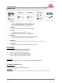
1. CERTIFICATIONS
“CE” Conformity
The round baler is a machine with "CE" marking in compliance with the
standards of the European Union described in 2006/42/CE Directive and
2004/108/CE Directive (Electromagnetic Compatibility), as shown in the “CE
Declaration of Conformity” provided with every machine.
FERABOLI S.p.A. declines all liability arising from use of the machine on products that do not
correspond to European standards.
If the machine should be sold to a third party, the declaration of conformity must be handed over together with
it.
Identification
The round baler is supplied with:
Operator's Manual
CE Declaration of conformity
Instruction handbook for the cardan shaft
Every machine is also provided with an identification plate showing:
Name and address of the manufacturer
“TIPO” = model of the machine
“N°” = serial number
“Massa kg” = weight of the machine
Machine Designation
Year of manufacture
"CE" marking
The information shown on the identification plate of the machine must always be quoted in any request for spare
parts and/or assistance.
Copy the machine information into the plate reproduced on the back of the cover for ease of
consultation. Keep this data in a safe place along with this manual’s code.
Certifications
1–1
MONDIALE Round Baler
1–2
Certifications
MONDIALE Round Baler
2. TECHNICAL DATA
MONDIALE Specifications
The technical data contained in the following tables are informative therefore we reserve the right to modify
them without obligation to give prior notice.
The symbol "÷" indicates a value lying between a minimum and a maximum.
DIMENSIONS
model
120 PRO
LU = Machine lenght
4050mm
LU esp = Lenght with ejector
4350mm
LA = Machine width
2520mm
LA est = External width
2760mm
H = Height
2435mm
WEIGHT
model
120 PRO
Weight
3450kg
Technical data
2–1
MONDIALE Round Baler
BALE CHARACTERISTICS
Diameter
1250mmm
Width.
1200mm
Weight (hay bale)
500kg
Weight (straw bale)
400kg
Weight (grass bale)
610÷950 kg
Hourly production
20÷45
TRACTOR REQUIREMENTS
PTO speed
540 g/1’
Required power minimum kw-cv
80 kw – 90 kw
Hydraulic system
n°.2 double-acting distributor
+ 1 single-acting distributor
25 liter/1’
Necessary oil flow rate
Electric system
12V = / negative mass
40km/h
Speed transport by road max.
(*) with tractor having a cabin
If a tractor without the cabin is used, ask the FERABOLI company for the special "ZMP2015 - Hydraulic Line Protection”.
CARDAN SHAFTS
model
120 PRO
series
3600167
TYRES
option
specifications
400/60-15.5 series
19.0/45-17
FLOTATION
500/50-17
Ply (P.R.)
14
14
14
Index radius (mm)
380
380
416
Speed (km/h)
40
40
40
2745
2800
3550
Pressure (bar)
3,5
3,9
3,8
External diameter (mm)
875
866
945
Wheel capacity (kg)
2–2
Technical data
MONDIALE Round Baler
PICK-UP
model
L
Max. collection width
2000mm
Width between tines
1869mm
Pitch between tines
69mm
Roll-holder diameter
250mm
N°. bars for roll-holder
4
N°. tines for bar
28
N°. of overall tines
112
Fixed
Support wheels
16.650 / 10
Dimensions of wheels /n° wrappers
Adjustment of working height
mechanical 13 positions
CONVEYING UNIT
model
120 PRO
25 *
N°. of knives
45
Pitch between knives
Knives control
hydraulic
Protection of knives
simple, spring-type
3-point star
Feeding rotor
(*) possibility to insert 13 or 12 knives, step 90
BINDING
type
NET
Reel diameter net
250÷300 mm
Yarn count of net
12÷16 g/m
Command
electronic
Max n. of conveyable reels
Technical data
1+1
FILM
1+1
2–3
MONDIALE Round Baler
FEATURES OF THE CONTROL SYSTEM
type
ICON
Power supply
11÷15 V Dc
Controls: membrane keyboard
16+1 keys
Display
Graphic LCD: 240x64 pixels
Back lighting
White LEDs
Microprocessor
16bit 24Mhz
Memories
Flash + Static RAM + Eeprom
Buzzer
Buzzer
Degree of protection
IP 65
Operating temperature
10°÷50°
Storage temperature
-10°÷70°
Relative humidity
90%
Container
ABS
Colour
Charcoal
Method of fastening
Magnet / Suction Cup
Overall size (max.)
102x 220x 40 mm
Weight
425g
Conforming to CE regulations
Yes
MODULES (sensors, motor controls, etc.)
Power supply
11÷15 V Dc
Degree of protection
IP 65
Operating temperature
-20°÷70°
Storage temperature
-30°÷80°
Relative humidity
100%
2–4
Technical data
MONDIALE Round Baler
3. GENERAL SAFETY REGULATIONS
In addition to the regulations contained in this operator's manual, observe the general regulations for safety and
accident prevention in force in your Country.
This machine has been designed and manufactured for the maximum safety at work. Maintenance of these
safety conditions is obligatory for the user.
Therefore, read this manual very carefully especially the safety regulations and with great attention to those
operations that are potentially very dangerous; if you do this while working it will be too late!
FERABOLI S.p.A. declines all and any liability for failure to observe the safety and accident prevention
regulations provided in this manual.
All and every liability for damage caused by the improper use of the round baler or modifications made
without authorisation is also declined.
Recognize safety information
This ALERT is a safety warning symbol.
When shown on the machine or in the manual, it alerts a potential for
personal injury.
Comply with precautions and follow all recommended safety operations.
This is the ALERT symbol for protecting mechanical parts, it indicates a
possible situation of danger.
This symbol is a WARNING reminder for the operator. It reminds the
operator to switch off the tractor and remove the key from the dashboard.
Whenever this symbol is found in the operator's manual, you must
switch off the tractor and remove the key from the dashboard before
carrying out the operations described.
Terminology adopted
Warning words are used with safety symbols: WARNING,
CAUTION (personal security) and IMPORTANT (mechanical parts
safeguard).
In this manual all the alert/warning safety points are shown by
those symbols and associated with a "signal word" which varies
depending on the immediacy or potential of the dangerous event.
WARNING!
The word WARNING indicates a potentially dangerous situation
that may result in death or serious injury if not avoided.
WARNING
CAUTION
IMPORTANT
CAUTION!
The word CAUTION indicates a potentially dangerous situation that may result in minor or moderate injuries if
not avoided.
IMPORTANT!
It warns that if the operations are not carried out correctly serious damage to the machine may result.
General safety regulation
3–1
MONDIALE Round Baler
Follow safety instructions
Before operating the machine:
• Learn how to properly use the machine and controls. Do not allow use by untrained persons and users that
haven’t read this operator’s manual.
• Periodically check the conditions of the machine as a whole, including all safety and protection devices.
Carefully read all safety messages contained in the manual and on safety signs applied to the machine.
Keep safety signs in good condition. Replace any missing or damaged safety signs.
Make sure that new equipment components and spare parts for repairs are complete with current safety
signs. Spare part safety signs are available from your FERABOLI dealer. (Spare parts and components
sourced from other suppliers may contain additional safety information not shown in this operator's manual).
• Keep your machine in proper operating condition
• All safety guards must be mounted and secured according to manufacturer instructions and must never be
tampered with. Any changes made without authorisation can compromise machine operation and/or safety
and shorten machine life.
If you do not understand any part of this manual and need assistance, contact your FERABOLI dealer.
WARNING!
Do not use the commands, pipes or other protruding parts of the machine as handholds.
Assemble, operate and disconnect the cardan shaft always according to information and safety
standards supplied for shaft use, contained in the manual provided by the shaft manufacturer and
delivered with the shaft itself.
The transport of persons or animals on the machine or on the tractor is strictly prohibited.
WARNING!
Use of the machine by any person who has not read and understood the information contained in this
manual is strictly prohibited.
Getting used to work in safe conditions
Learn maintenance procedures before starting work. Keep the area clean and dry.
Keep hands, feet and clothing far away from moving parts.
Never lubricate, service, or adjust the machine in motion.
Disengage all motion transmission components and operate controls to relieve pressure.
Lower equipment to the ground.
Stop the engine.
Remove the ignition key.
Let the machine cool down.
Securely support any machine components that must be raised for maintenance. Keep all parts in good
condition and properly installed.
Immediately repair any damage.
Replace any worn or broken parts (always use original FERABOLI spare parts and components).
Remove any build-up of grease, oil or debris.
On towed equipment, before servicing electrical system components or welding on the machine,
disconnect electrical wiring from the tractor
3–2
General safety regulation
MONDIALE Round Baler
Protecting persons and animals
Do not allow the passage or stopping of any person close to a machine in operation.
During operation, keep people, livestock and pets away from the working area of the machine.
Preparing for emergencies
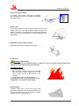
Be prepared in the event of a fire.
Keep an extinguisher and first aid kit on hand.
Keep emergency service numbers near the telephone:
doctors, ambulance service, hospital, and fire.
Individual protection devices (D.P.I.)
Wear suitable clothing during operations.
Wear close fitting clothing and safety equipment
appropriate to the type of work being performed. Never
wear loose clothing that could become hooked in the
mechanisms and the moving parts of the machine.
Long hair must be pulled back.
During maintenance and repair operations, use of the following protections is required:
safety gloves
safety shoes
visor and/or safety goggles
Safe operation requires the full attention of the operator. Do not wear headphones for the radio or music while
operating the machine.
Prolonged exposure to noise can cause impairment or loss of hearing. To guard against or uncomfortable loud
noises, wear a suitable hearing protective device such as headphones or earplugs.
In the case of work or maintenance operations which generate dust or substances harmful to your breathing,
use suitable D.P.I.
Sound Levels
CAUTION!
Observe the regulations in force in your Country
regarding the acoustic protection to be used
In some circumstances the noise level produced may
exceed 85dbA÷90dbA. In these cases it is advisable to
use suitable personal protection equipment.
General safety regulation
85dbA÷90dbA
3–3
MONDIALE Round Baler
Safe machine mainenance
Tie back long hair. Do not wear necktie, scarves, loose
clothing, or necklaces when operating the machine or
moving parts. Severe injury can be caused if these
items get caught in the machine.
Remove rings and other jewellery to prevent electrical
shorts and entanglement in moving
Keep away from rotating parts of the transmission
Entanglement in rotating shafts can cause serious
injury or death.
Make sure that tractor and drive shaft guards are
always mounted and that rotating guards can rotate
freely.
Wear close fitting clothing. Stop the engine and make
sure the PTO transmission shaft has come to a
complete stop before performing adjustments and
connections, and before cleaning PTO controlled
equipment.
Range of action of the machine
The range of action of the machine is to be considered
a hazardous area: before operating the machine, make
sure that there are no people or animals within the
borders of the work area. If any are present, stop the
machine and remove them.
The user of the baler is liable towards third parties
for damage caused by the machine within this
range.
Dangers associated with high pressure
Splashes of liquid under pressure can penetrate the
skin and cause serious injury.
To avoid personal injury, relieve pressure before
disconnecting hydraulic hoses or other lines. Tighten all
fittings before restoring pressure.
Use a piece of cardboard to identify leaks.
Protect hands and body from high pressure liquids. In
case of injury, contact a doctor immediately.
Any fluid injected into the skin must be surgically
removed within a few hours or gangrene may result.
Medical personnel unfamiliar with this type of injury
should consult appropriate medical documentation.
Hydraulic couplings must always be perfectly clean. Always cover them with the plastic protective caps
supplied after each use to avoid getting them dirty or damaging them.
Check and, if necessary, replace any damaged pipes or fittings. All flexible hoses should be replaced after 5
years from the date stamped on the hose.
3–4
General safety regulation
MONDIALE Round Baler
Complying with maximum transport speed
IMPORTANT!
Maximum transport speed is determined by the local highway code and the capabilities of this
machine.
When driving on public roads, always comply with road rules.
When towing this machine at transport speed, do not exceed its gross weight (GVW).
Some tractors are able to operate at higher speeds with respect to the maximum transport speed of this
machine. Regardless of the maximum speed that the tractor used to tow this machine can reach, do not
exceed the maximum machine transport speed.
.
IMPORTANT!
Exceeding the speed of transport of the machine can result in:
loss of control of the tractor/machine unit
reduction or total absence of braking
damage to machine tyres
damage to structure or components of the machine
When towing loads on surfaces in poor condition, around corners or on slopes, proceed with caution
and further reduce speed.
Ballast, wheel distance and tyre inflation check
Make sure that the ballast, the distance of wheels and tyre inflation are suitable to the type of tractor and that
they ensure proper machine stability in all conditions, especially for use on hilly terrain and in adverse
conditions. Consult the tractor operator's manual.
Use lights and safety devices
Prevent collisions with other road users, slow tractors with mounted or trailed equipment and self-propelled
machinery. Frequently check vehicles arriving from behind, especially before turning corners, and use turn
signals.
Use the headlights, turn signals and warning indicators both at night and during the day. Comply with road
rules regarding lighting vehicles and various signalling. Maintain lights and different signalling means visible
and in good condition.
Replace or repair lighting and damaged or lost signalling devices.
Electrical lines
Be very careful to keep a minimum safe distance when
operating near electric power lines. The machine is
mainly constructed of metal; therefore, if it should come
in contact with electrical lines or there is a discharge
between the line and the machine, the operator risks
fatal harm.
In the case of operation in the vicinity of electric power
lines, contact the authority responsible for power
distribution.
General safety regulation
3–5
MONDIALE Round Baler
Keep heat sources away from pressurised fluid tubes
The heating of tubes containing fluid under pressure
can cause a spray of flammable vapour, causing
severe burns to the person working and to people
around.
During welding or brazing operations or when using
open flames, do not heat the areas near the
pressurised fluid tubes or other flammable materials.
The heat in the area just beyond the tip of the flame
can cause the accidental explosion of pressurised
tubes.
Support the machine properly
Before performing any work on the machine, always
lower the component or equipment to the ground.
Provide adequate support if the servicing to be
performed requires machine or equipment lifting.
Hydraulically supported devices, if kept in the raised
position, may settle or drop because of leakage.
Do not use cinder blocks, bricks or other material that
could give out under a continuous load to support the
machine. Never work under a machine supported only
by a jack. Always follow the instructions in this manual.
When using equipment or accessories together with the
machine, always follow the safety precautions listed in
the accessory or equipment operator's manual.
Removal of paint before welding or heating
Avoid potentially toxic fumes and dust.
The heating of paint during welding operations or when
using a flame can generate hazardous fumes.
Before heating:
Remove paint over an area of at least 100mm in
diameter around the point that will be affected by
heating. If you cannot remove the paint before
heating or welding, wear an approved respirator.
Do not breathe in dust when you sand or grind paint.
Wear an approved respirator.
If using a solvent or paint stripper, remove residues
with soap and water before starting welding
operations. Keep solvent or paint stripper containers
away from other flammable material.
Allow fumes to disperse for at least 15 minutes
before welding or heating.
Do not use chlorinated solvents in welding areas.
Perform all work in a well-aerated area where toxic
fumes and dust can be vented.
Properly dispose of paint and solvent
3–6
General safety regulation
MONDIALE Round Baler
Avoid applying high pressure on safety labels
Pressurised water can damage or remove safety labels.
Avoid applying high pressure directly on safety labels
Immediately re-apply missing safety labels or replace
damaged ones. Spare safety labels are available from
your FERABOLI dealer.
Avoid applying high pressure on cylinders
.
Avoid applying high pressure directly on cylinders,
because pressurised water can damage cylinders.
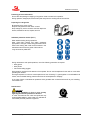
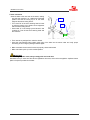
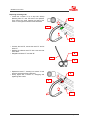
Cardan shaft safety
Each cardan shaft is equipped with a safety system to
protect mechanical parts against high starting torque
and maximum torque:
“LR” = with automatic torque limiter.
LR
Cardan safety chain
Prevents cardan shaft guard rotation during work.
Fasten to the steering head.
General safety regulation
3–7
MONDIALE Round Baler
Ecology and pollution
Respect the laws in your country concerning the use and disposal of products used for machine
operations, maintenance and clearing.
Improper disposal of waste can threaten the
environment and ecological system. The components
used for FERABOLI equipment which are potentially
hazardous waste include: oil, brake fluid and filters.
Use airtight containers for drained fluids. Do not use food or beverage containers that may mislead
and cause accidental drinking.
Do not drain onto the ground, into sewage systems or in watercourses.
Dispose of any remaining machine packaging in suitable sorted waste containers.
Consult the relevant authorities for disposal or recycling centres. If the machine is scrapped observe
the anti-pollution laws of your Country.
Residual risks
In spite of the fact that many risks have been examined and, where possible, the necessary precautions taken
to reduce the risks involved during the working phases of the machine, there still remains a series of residual
risks. These are listed below:
Risk of crushing, dragging, in the instance of contact with the moving parts of the machine during the
shearing, death
working phase:
IT IS PROHIBITED TO CROSS THE WORKING AREA DURING
OPERATION.
IT IS PROHIBITED TO CLIMB ABOARD THE MACHINE WHILE ITS
PARTS ARE IN MOTION..
Risk of collision
With the moving parts of the machine during work:
IT IS PROHIBITED TO CROSS THE WORKING AREA DURING
OPERATION.
IT IS PROHIBITED TO CLIMB ABOARD THE MACHINE WHILE ITS
PARTS ARE IN MOTION.
Risk of crushing, shearing, In the instance of contact with the moving parts of the hydraulic lifting
entanglement.
system with hydraulic operated rear sliding tailgate:
IT IS PROHIBITED TO STAND WITHIN THE WORKING AREA OF
THESE DEVICES.
3–8
General safety regulation
MONDIALE Round Baler
4. SPECIFIC SAFETY REGULATIONS
Safe baler use
WARNING!
Never leave the machine unattended during operations.
Never leave the tractor unattended with the engine running.
Do not allow the use of the machine by children or unqualified persons, or anyone not in good
health or not in possession of a valid driver's license.
Before use, always check road conditions and general safety conditions of the machine.
WARNING!
Always perform the following
operations before entering the
working area of the machine:
Disconnect the power take-off (PTO).
Stop the tractor engine.
Remove the main switch key.
Engage the parking brake.
Wait for all moving parts to come to a complete
stop.
Switch off the ICON Control system.
Relieve hydraulic pressure.
During machine operation, the presence of persons near moving parts is strictly prohibited, as is touching
moving parts or standing between them. Keep your face, hands and feet away from moving parts. Keep at a
safe distance.
WARNING!
To avoid serious injury or death caused by remaining caught in the machine, DO NOT attempt to
manually feed product, twine or net into the baler with hands or feet or with the aid of any other objects
and do not unclog the feeding zone WHILE THE BALER IS IN MOTION.
The machine feeds product faster than it can discharge it.
In the event of product flooding in the feeding zone:
Stop the tractor, remove the keys from the dashboard and wait for all moving parts
of the machine to come to a complete stop.
Switch off the ICON Control system.
Circulation on the road
IMPORTANT!
Never circulate on public and/or private roads with a bale in the baler chamber. Always empty the
chamber before leaving the field and make sure that the hatch is closed and locked.
Before towing the machine, withdraw the locking unit in the transport position.
Specific safety regulation
4–1
MONDIALE Round Baler
Bale expulsion/discharge danger
Do not stand behind the machine. The hatch may be
open and the bale may eject.
Discharge bales on flat ground or in a suitable position,
in the case of sloping ground.
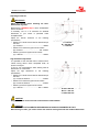
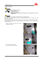
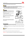
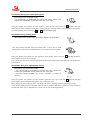
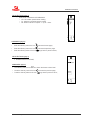
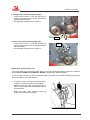
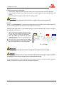
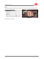
Tailgate safety lock device
There is a safety measure to lock the tailgate when it's open, to avoid its accidental closure when the operator
is inside the machine to perform maintenance and/or repairs.
When the tailgate is open, adjust the "L" lever placed on the block valve to the standstill position (closed
lock).
L
IMPORTANT!
Remember to disengage the tailgate safety device by turning the lever to its original position before
closing the tailgate.
4–2
Specific safety regulation
MONDIALE Round Baler
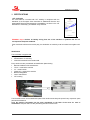
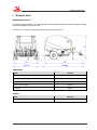
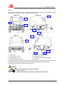
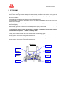
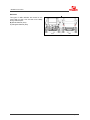
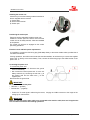
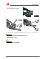
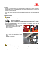
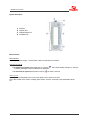
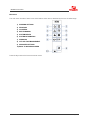
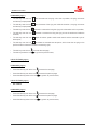
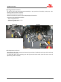
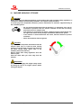
Covers
The machine is equipped with covers. These protect the operator from moving mechanical parts and shelter
these same mechanical parts from any accidental intrusion of debris.
FRONT view
RIGHT side
4
1
2
3
7
5
REAR view
LEFT side
4
8
7
5
1)
2)
3)
4)
Closing cover
Transmission box cover.
Cardan protection cover.
Side covers (right and left side).
5)
6)
7)
8)
6
Pick-up covers (right and left side).
Pick-up security cover.
Transmission covers (right and left side).
Rear cover.
The lateral gull-wing door protection guards are provided with a safety lock that ensures perfect closing of the
protection guard with the machine and thus prevents accidental opening during work or transport.
To open the protection guards a 13mm spanner is required.
WARNING!
Before removing any covers or protective shields:
• Stop the machine.
• Switch off the tractor and remove keys from the tractor dashboard.
Specific safety regulation
4–3
MONDIALE Round Baler
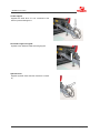
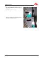
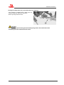
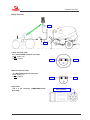
Cardan support
Supports the shaft when it is not connected to the
tractor to prevent damage to it.
Rod holder support and guide
Hydraulic hose, electrical cable and wiring support.
Hydraulic hose
Supports hydraulic hose when the machine is in standby.
4–4
Specific safety regulation
MONDIALE Round Baler
Pick-up transmission safety
The feeding device motion transmission is equipped
with a safety with two shear bolts against overloading
and foreign bodies.
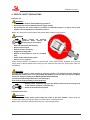
Blades safety
As protection against the entry of foreign bodies into the machine
(stones, sticks, etc.) that may cause the blades to break, each
blade is mounted on a retractable spring system that allows the
blade to lower automatically and then to return automatically to the
work position.
Managing the binder blades and knives
Wear safety gloves when managing binder blades
In case of fire
WARNING! RISK OF FIRE
Regularly remove the accumulated product to reduce the risk of fire and to prevent material from
twisting around mechanical machine components.
If the bale catches fire:
1. Immediately eject bale.
2. Move the tractor and baler as far away as possible
from flammable material, making sure the wind
does not blow the fire in the direction of the
machine.
3. Lift the hatch and insert the locking device.
To extinguish the fire, use a pressurised water fire
extinguisher or an alternative water supply.
Parking wedges
Positioned under tyres to block the machine and
prevent any accidental movement while parked and any
time the machine needs to be blocked for repair,
maintenance or cleaning operations.
Specific safety regulation
4–5
MONDIALE Round Baler
4–6
Specific safety regulation
MONDIALE Round Baler
5. PICTOGRAMS
Safety symbols / Pictograms
Adhesive signs containing important messages for personal safety are affixed on the machine. Their purpose is
to call the operator's attention to safety and health guidelines, as well as to possibly dangerous work and
maintenance situations.
These safety signs are black and red pictograms on a yellow background.
They should always be kept clean and legible and must be replaced immediately whenever they have been
removed and/or damaged.
When putting on new ones or painting areas where they were present, safety signs must be replaced as they
were found originally.
For this purpose, each adhesive contains a Spare Parts Service order code number. When requesting
adhesive safety signs from our Spare Parts Service department, specify relative codes.
To receive the full range of safety signs stickers for the baler, request the following code from our
Spare Parts Service department: “7Z00649 = CE Safety decal”
All safety signs decals on the baler are shown and described on the following pages.
Read and understand the meaning of the signs and disseminate this information to your staff and anyone else
who may approach the machine during work or maintenance.
Read and understand the meaning of the signs and disseminate this information to your staff and anyone else
who may approach the machine during work or maintenance.
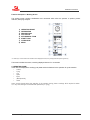
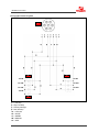
Pictograms position on the round baler.
FRONT view
7500726
7500185
7500186
7500187
7500208
7500207
7500187
Pictograms
7500781
7500210
7500207
7500221
5–1
MONDIALE Round Baler
RIGHT side
7500203
inside
7500724
7500198
7500203
inside
inside
7500221
7500203
LEFT side
7500203
inside
7500198
inside
7500221
7500203
BACK view
7500212
7500197
5–2
7500201
Pictograms
MONDIALE Round Baler
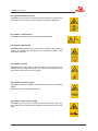
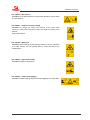
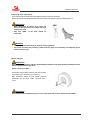
cod. 7500185 – Operator’s manual
Before operating the machine, at the beginning of each season and before
working on the machine, read and keep in mind the use and maintenance
instructions in the operator's manual.
cod. 7500186 – Repairs and maintenance
CAUTION! Before doing maintenance or repairs on the machine, switch off
the tractor engine, remove the keys from the dashboard and read the
operator's manual.
cod. 7500187-1 – PTO rpm
CAUTION! Machine suitable for tractors with PTO a 540rpm/1' and direction
of rotation.
cod. 7500197 – Lifted hatch
WARNING! Do not stand behind the machine to avoid being crushed by
sudden manoeuvres.
cod. 7500198 – Opening the hatch
WARNING! Do not move or stand under the hatch when it is lifted unless the
appropriate safety catches have been inserted, to avoid crushing.
Pictograms
5–3
MONDIALE Round Baler
cod. 7500199 – Maneuvering area
WARNING! Do not enter the manoeuvring area between the machine and
the tractor when the motor is running. This area is particularly dangerous.
cod. 7500201 – Electrical lines
WARNING! Take great care when working near electrical lines.
cod. 7500203 – Moving parts
WARNING! Before performing any work, wait for all parts of the machine to
come to a complete stop and prevent any unwanted movement using
appropriate equipment.
cod. 7500207 - Feeding
WARNING! Never hand feed or remove material in front of the pick-up
collector as long as parts are moving. This could cause entrapment of the
upper limbs or more severe injury to persons.
cod. 7500208 – Hydraulic system
WARNING! Consult the operator's manual before working on the hydraulic
system.
Pressurised oil can cause serious infections.
cod. 7500210 – Upper limbs crushing
WARNING! Do not remove the guards and do not touch parts, which may
also suddenly move under their own weight and cause crushing of the upper
limbs..
5–4
Pictograms
MONDIALE Round Baler
cod. 7500212 – Bale ejection
WARNING! Do not stand behind the machine when the bale is ejected. Keep
at a safe distance.
cod. 7500221 – Danger of crushing / cutting
WARNING! Do not get too close to the machine, as this could cause
crushing or cutting of the lower limbs, due to the weight or lowering of the
machine.
Keep a safe distance.
cod. 7500724 – Safety lock
WARNING! Before entering the bale forming chamber to do any operations
or for other reasons, lock the hydraulic jacks by turning the valve to the
closed position..
cod. 7500726 – Upper limbs cutting
WARNING! Danger of cutting hands.
cod. 7500781 – Cardan shaft dragging
WARNING! Danger of getting caught and being dragged by the cardan shaft.
Pictograms
5–5
MONDIALE Round Baler
Reflectors
Two types of reflex reflectors are located on the
round baler so that it can be seen more clearly
during road transport:
R) Round reflectors (front).
T) Triangular reflectors (rear).
T
R
R
Front
5–6
T
Rear
Pictograms
MONDIALE Round Baler
6. PREPARING THE TRACTOR
WARNING!
Take extra care as tractor connection operations can be dangerous.
Use a tractor with the appropriate characteristics for towing the machine in use.
Make sure that there are no objects resting on the machine and that there are no persons and/or animals in the
immediate vicinity.
The machine steering head is equipped with a pivoting towing eye.
IMPORTANT!
Before adjusting the steering head, make sure that:
• tyres are properly inflated
• the hatch is closed
Preparing the tractor
6–1
MONDIALE Round Baler
Adjusting the tow-bar
IMPORTANT!
Adjust the tow-bar before attaching the baler.
Reassemble all guards.
Machines exit FERABOLI S.p.A. with a "STANDARD"
tractor connection.
If necessary, use of a "P" extension for standard
attachment of your tractor is permitted within
acceptable limits.
Adjust the tow-bar extension to the following
specifications:
between PTO shaft end and tow-bar attachment pin
hole axis
(A) = distance .............................................. 300mm
between PTO shaft and upper tow-bar surface
(B) = distance ..................................... 160 - 290mm
between ground and upper tow-bar surface
(C) = distance .............................................. 450mm
A = 300 mm
B = 160÷290 mm
C = 450 mm
High attachment adjustment
It is possible to hook the baler also to tractors with a
"HIGH" towing device, within acceptable limits, as
shown in the figure.
To do so, you must adapt the baler steering head to
attachment "A" of the tractor.
Adjust the high attachment to the following
specifications:
between PTO shaft end and tow-bar attachment pin
hole axis
(A) = maximum distance ............................... 200mm
between PTO shaft and upper tow-bar surface
(B) = maximum distance ............................... 200mm
between ground and upper tow-bar surface
(C) = distance .................................... 800 - 1050mm
A max = 200 mm
B min. = 200 mm
C = 800÷1050 mm
CAUTION!
A high attachment can be used with a measurement of 800-1050mm.
CAUTION!
THE USE OF HIGH ATTACHMENTS WHEN DRIVING ON ROADS IS PROHIBITED IN ITALY!
When driving on roads, you need to restore the machine steering head with the standard attachment!
6–2
Preparing the tractor
MONDIALE Round Baler
Selecting the tractor PTO regime
To select the tractor PTO regime, refer to the label on the front of the baler.
The direction of rotation is that which is indicated by the adhesive safety sign
Baler with PTO regime at 540 rpm/min:
The size of the tractor PTO shaft must be 3.5 cm (13/8
in.).
Consult the tractor operator's manual to install an
appropriate PTO shaft and adjust PTO regime.
IMPORTANT!
Stop the PTO during reverse manoeuvres at the
end of a swath and when steering at a very narrow
angle.
Preparing the tractor
6–3
MONDIALE Round Baler
Installing the control unit
Check that you have the following material contained in
the box supplied with the machine:
1) Power cable
2) ICON control terminal
3) Suction pad
Positioning the suction pad
Fasten the suction pad stably inside the tractor cab.
Position the suction pad in the tractor cab so that the
control unit can be easily reached, visible and available
to the operator.
The control unit will then be engaged on the suction
pad during operations.
Electrical circuit and baler power requirements
It is possible to connect the field wiring plug (DIN 9680) directly to the tractor female socket, provided that it
can deliver 25÷30 AMP.
If during operations, the ICON control terminal shows abnormalities, we advise that you connect the supplied
power cord “1” directly to the tractor battery. Then, connect the field wiring plug to the COBO socket on the
power cord “1”.
Connecting the power cord
To connect the power cord:
with the tractor turned off, disconnect the ground
wire from the battery,
then connect the tractor's power cord “1” to the 12V
battery terminals, by connecting the red wire (+) to
the positive pole and the black wire (-) to the
negative pole.
Now reconnect the ground wire.
IMPORTANT!
Be careful not to invert the poles:
RED wire “+” (positive)
BLACK wire “-” (negative)
Fasten the "1" tractor power cable along the tractor, bringing the COBO connector to the height of the
towing eye or near the PTO..
IMPORTANT!
Make sure that the tractor power cable, once connected to the machine cable, does not hit against the
PTO and does not interfere with working operations.
6–4
Preparing the tractor
MONDIALE Round Baler
7. PREPARING THE BALER
NET binder
Selecting the net roll
The baler is equipped for use with standard type reels.
For best performance, use 14÷16 g/m net rolls.
The round baler can use spools from 2000 to 3000 metres.
The hole inside the cardboard tube of the roll of net must be 75÷78mm.
IMPORTANT!
Higher density net rolls can be used. In this case,
make sure that the net binding device is properly
adjusted and the blade is sharp.
Net roll diameter “D” must not exceed 30 cm.
D = diameter, max 30cm
L = length of the net holder tube 1260mm
Taking care of the net roll
IMPORTANT!
Protect the net roll from humidity and impact. Do not remove the protective cover before use.
Protrusions can cause erratic performance and affect bale weather resistance. Do not use tape directly
on the net.
Store the roll in a cool, dry place away from direct sunlight.
Preparation of the baler
7–1
MONDIALE Round Baler
Loading the net binder
WARNING!
Before installing the net binder, ,:
disconnect the PTO,
engage the parking brake,
stop the tractor engine and remove the key. Wait for all moving parts to come to a
complete stop
CAUTION!
Pay close attention to the blade of the binder during any nearby operations.
The ICON control system needs to be turned on to move the binder arm in order to perform some of the
operations described below.
More information for turning on the ICON control system can be found under the “ICON Control System / Main
functions” section; more information on moving the binder arm can be found under “ICON Control System / Main
menu / Motor manual”
Attach the net brake to the binder arm in order to
disengage the net brake.
Turn on the ICON control system.
Move the binder arm into the chambre.
7–2
Preparation of the baler
MONDIALE Round Baler
Extract plug "A", which fixes the net roll holder tube,
and extract the "T" tube in order to insert the roll.
A
T
Insert the net roll on the appropriate net holder tube
and reposition it.
Secure it again with the previously removed "A"
safety pin.
IMPORTANT!
Take great care to push the net roll onto the tube
correctly so that it rotates in the right direction as
shown on the decal.
Lift the front cover.
Braid the ends of the net and pass it onto the rollers
according to the position indicated on the sticker
applied to the machine.
Then, complete the insertion of the net in the lower
part of the path and let approximately 20cm of the
net hang.
Lower the front cover.
Preparation of the baler
7–3
MONDIALE Round Baler
After having positioned the net into the rolls, and
before starting to work, return the binder arm to a
resting position.
Switch off the ICON control system.
Detach the roll brake from the binder arm in order to
always keep the roll brake inserted.
7–4
Preparation of the baler
MONDIALE Round Baler
8. CONNECTION AND DISCONNECTION
CONNECTION
WARNING!
Take extra care as tractor connection operations can be dangerous.
Take heed of all basic safety regulations, as contained in chapters “General safety regulations” and
“Specific safety regulations”.
Use a tractor with the appropriate characteristics for towing the machine in use.
Make sure that there are no objects resting on the machine and that there are no persons and/or animals in the
immediate vicinity.
The machine steering head is equipped with a pivoting towing eye.
The baler steering head can be adapted to the tractor towing device, which can be "STANDARD" or "HIGH".
In any case, the towing eye must always be parallel to the ground.
Connection and disconnection
8–1
MONDIALE Round Baler
Steering head adjustment
The machine steering head can be adapted to the
tractor only vertically.
In high position it can be used with the “HIGH” tractor’s
towing attack.
WARNING!
THE USE OF HIGH ATTACHMENTS WHEN DRIVING ON ROADS IS PROHIBITED IN ITALY!
When driving on roads, you need to restore the machine steering head with the standard attachment!
WARNING!
Take extra care as steering head adjustment operations can be dangerous.
To avoid injury from unexpected movement, support the machine firmly on flat, horizontal ground.
Take heed of all basic safety regulations, as contained in chapters “General safety regulations” and
“Specific safety regulations”.
8–2
Connection and disconnection
MONDIALE Round Baler
Unscrew and remove the two V2 screws (one per
side)
Loosen the two V1 screws (one per side)
V2
V
V1
V2
V1
Then adjust the position of the draw bar by moving it and inserting the two previously removed V2 screws into
the hole (one screw per side).
Tighten the two V2 screws again (one screw per side).
Tighten the two V1 screws again (one per side).
IMPORTANT!:
Tighten both V2 screws to: 1150Nm
Tighten both V1 screws to: 1700NM
Connection and disconnection
8–3
MONDIALE Round Baler
Adjusting the tow-bar / towing eye
The towing eye can be adapted to the tractor
attachment and the cardan shaft position, adjusting it to
the height or else overturning it.
CAUTION!
Take extra care as towing bar / towing eye adjustment operations can be dangerous.
To avoid injury from unexpected movement, support the machine firmly on flat, horizontal ground.
Take heed of all basic safety regulations, as contained in chapters “General safety regulations” and
“Specific safety regulations”.
8–4
Connection and disconnection
MONDIALE Round Baler
Loosen the V1 screw
Unscrew and remove the two V2 screws
V2
V
V1
V1
V2
Then, adjust the position of the towing eye by inserting the two previously removed V2 screws into the holes.
IMPORTANT!
The towing bar / towing eye must always be parallel to the ground.
Tighten again the two V2 screws
Tighten again the two V1 screws
IMPORTANT!
Tighten both V1 and V2 screws to: 350Nm
Connection and disconnection
8–5
MONDIALE Round Baler
Tractor connection
• Hook the baler to the rear hook of the tractor, making
sure that the machine is in a stable and horizontal
position and that the towing eye is at the same
height as the tractor towing device.
• Turn crank "M" of the servo steering head to lower
or raise the towing eye to obtain correct alignment
with the tractor towing device.
• Insert cotter "S" in the towing eye and secure it with
a safety pin. Then lift the servo steering head with
the crank "M".
M
S
Then remove any wedges from under the wheels.
• Insert the road transport light system power plug of the baler into the tractor outlet and verify proper
functioning of all turn signal, parking and brake lights.
Make sure that the hatch and all covers are properly closed and hooked.
• Make sure that the pick-up is in the raised position.
IMPORTANT!
When driving on public roads, always comply with local road rules.
Remember that you must have the vehicle registration document, and must have applied a duplicate license
plate in the space provided on the baler.
8–6
Connection and disconnection
MONDIALE Round Baler
Hooking the safety chain (only in countries where it is expected)
If the machine is equipped with a safety chain (A),
hook and fasten the chain (A) to the tractor.
Allow only enough slack for turns.
CAUTION!
The chain must stop the steering head from hitting the ground in the event that the baler
accidentally becomes removed from the tractor.
Connection and disconnection
8–7
MONDIALE Round Baler
Connecting the telescopic shaft to the PTO shaft of the tractor
CAUTION!
The cardan shaft is a transmission component (machine), equipped with a "CE" certificate.
Each cardan shaft is equipped with a use and maintenance manual. Always carefully follow information
and safety standards supplied for shaft use as contained in the manual.
Never connect the telescopic shaft when the tractor is moving.
Never use an iron hammer to connect or disconnect the telescopic shaft from the PTO.
IMPORTANT!
The ribbed profiles of the telescopic shaft and of
the PTO must always be free of any paint, dirt, chaff
or burrs.
Be very careful when connecting the shaft. Check that
it is properly locked on the PTO.
The cardan shaft attachment, on the tractor side, is
highlighted by a decal on the cardan itself.
Check that the length never exceeds the minimum
distance between the machine and the tractor (risk of
jamming).
Minimum clearance must be 4cm.
When the cardan shaft is fully extended, the telescopic
shafts must overlap by at least 1/3 of their length in all
working conditions.
Before starting operations:
Verify that the safety buttons and screws are properly engaged in the PTO grooves and make sure that
the protection turns freely, otherwise it will need to be greased.
Verify that the appropriate safety chains are present on guards to prevent guards from rotating with the
cardan shaft.
Verify protective caps often and, if they are not completely in good condition, replace them immediately
with new protections.
WARNING!
After all maintenance operations performed on the cardan shaft, always reset protective caps on the
shaft itself.
During baler operations, replace the cardan shaft support along the steering head side.
FERABOLI S.p.A. declines any responsible for any consequences of failure to heed warnings.
8–8
Connection and disconnection
MONDIALE Round Baler
Cardan shaft decal
There is a sticker on the cardan shaft which requests
the operator complies with safety standards for shaft
use.
FERABOLI S.p.A. declines any responsible for any consequences of failure to heed warnings.
C Connecting the seven-contact outlet for towing
Connect the road driving light outlet to the sevencontact outlet of the tractor.
The electrical cable of the road driving lights of this
machine meets the requirements of ISO 1724
Connection and disconnection
8–9
MONDIALE Round Baler
Connection to the hydraulic system of the tractor
WARNING!
The maximum working pressure in baler flexible hydraulic hoses is approximately 20,000 kPa (200 bar;
2900 psi).
To prevent accidents due to the splashing of fluids under pressure, before connecting or
disconnecting hydraulic hoes or other fluid hoses, stop the engine and discharge pressure from the
hydraulic system.
Tighten all joints before restoring pressure.
IMPORTANT!: All hydraulic attachments must
be free of dirt, dust or sand. Protect openings with
plugs until connected. Debris can damage the
hydraulic system.
NOTE: The baler is equipped with ISO hydraulic
attachments.
If these are not suitable for tractor attachment joints,
contact your FERABOLI dealer for proper attachment
joints.
A = diameter
B = lenght
(A) = diameter .................................. 23,66 ÷ 23,74 mm
(B) = lenght ........................................................ 24 mm
Connecting flexible hydraulic hoses for lifting the collector and hatch
Using force, insert the ends of the hoses in the tractor
attachments.
To permit the hatch to function, connect the flexible
hydraulic hoses (A) of the hatch to a double acting
hydraulic distributor. When the tractor hydraulic
distributor lever is moved backward, the hatch should
open.
Connect the flexible hydraulic hose (B) for lifting the
collector to a single acting hydraulic distributor. When
the tractor hydraulic distributor lever is moved
backward, the collector should raise.
Connect the flexible hydraulic hose (C) to a double
acting hydraulic distributor to open and close the cut
group.
NOTE: To connect the flexible hydraulic hose to the
connector to the recommended outlet, refer to the
tractor Operator's Manual.
Before lifting the pick-up:
• Position the stop valve lever to the "OPEN" position
and then left it (transport position).
• Then turn the valve lever to the "CLOSED" position
to lock it.
8–10
CLOSED
OPEN
Connection and disconnection
MONDIALE Round Baler
Installing and connecting baler wiring to the ICON control terminal
IMPORTANT!
Make sure that no cables are a hindrance to driving maneuvers and are not near moving parts.
Make sure that the tractor power cable, once connected to the machine cable, does not hit against the
PTO and does not interfere with working operations.
Connect the signal cable "CS" (equipped with 24-pole rectangular connector) to the control unit plug and
tighten the ring nut.
Then insert the control unit in the dovetail that was previously installed in the cab.
Connect the machine power cable "CM" with the tractor power cable "CT."
Make sure that the tab of the COBO female connector cover of the machine power cable is engaged in
the COBO connector slot of the male COBO connector of the tractor power cable.
This will prevent accidental disconnections of the two cables which would result in a system black-out.
Now verify that the control unit switches on by pressing the relative button. If cables have been properly
connected, the system will switch on.
CS
CT
CM
Further information about how to turn on the ICON control system are described in chapter “ICON Control
System / Main functions”.
Connection and disconnection
8–11
MONDIALE Round Baler
DISCONNECTION
Disconnecting the cardan shaft from the PTO shaft of the tractor
Disengage the PTO, engage the parking brake, stop
the engine and remove the ignition key.
To disconnect the telescopic shaft properly from the
PTO shaft, refer to the telescopic shaft operator's
manual.
Replace all protections, if removed.
Repositioning the cardan shaft
When adjusting the baler steering head for use with
the tractor towing hook, position the support as shown
in the figure, so as to rest the telescopic shaft on itself.
Arranging the flexible hydraulic hoses
CAUTION!
Splashes of liquid under pressure can penetrate the skin and cause serious injury. To avoid personal
injury, relieve pressure before disconnecting hydraulic hoses or other lines.
Disconnect the flexible hydraulic hoses and install caps
on the attachment joints.
Arrange the flexible hydraulic hoses in their relative
support to keep them clean, preventing them from
coming into contact with the ground.
Disconnecting from the tractor
Before disconnecting the baler from the tractor:
Move crank "M" to lower the servo steering head to
the ground.
Remove cotter "S" from the towing eye and move
the tractor away from the machine.
8–12
M
S
Connection and disconnection
MONDIALE Round Baler
9. TRANSPORT AND PARKING
Towing the baler on public roads
WARNING!
When towing this machine on public roads, it is advisable to use signalling lights and turn signals.
•
•
•
Never use the machine as a means of transport for goods and/or people.
It is strictly forbidden to drive the baler with bales on board.
Do not operate the baler during towing.
CAUTION!
Use caution when moving the towed baler. Reduce speed if the weight of the baler exceeds the weight
of the tractor. The baler must be empty during road transport.
During road transportation, the round baler must be empty, all components in transportation mode and
all safety devices inserted.
IMPORTANT!
Avoid tight turns when towing the baler. Considerable damage can be caused if the steering head
should hit into tractor tyres.
IMPORTANT!
The maximum driving speed is determined by local road rules and by tyre size. Consult the "Tyre"
paragraph in the "Technical Data" chapter to determine the maximum permitted speed for each tyre
and for the baler.
Transport and parking
9–1
MONDIALE Round Baler
9–2
Transport and parking
MONDIALE Round Baler
10. BALER USE
IMPORTANT!
All operations should be performed by a single operator who must have read and understood all parts
of this manual, particularly the chapters regarding safety.
Before starting work, verify that the machine is all in order, that lubricating oils are at the right level and that all
parts subject to wear and tear are fully efficient..
CAUTION!
Unless otherwise specified in this operator's manual, adjustment and preparation for work must only
be carried out with:
•
•
The tractor switched off and keys removed from the dashboard.
The machine switched off and blocked stably on the ground.
After making the connections described in the chapter ”Connection and disconnection”:
Switch on the tractor without engaging PTO and verify proper functioning of the various baler
movements.
Verify functioning of the hydraulic system: the opening and closing of the hatch, raising and lowering of the
pick-up (remember to bring the stop valve lever to the "OPEN" position to raise the pick-up).
Verify functioning of electrical connections to the terminal: switch on the "ICON" control system.
Verify functioning of the electrical system, turn signal, parking and brake lights.
Engage PTO.
IMPORTANT!
Before you perform these verifications, make sure that no one is in the vicinity. Operate for the first
time with caution, verifying correct operation of all mechanical and transmission components.
Baler use
10–1
MONDIALE Round Baler
Running in
Consider the first fifty bales as a break-in period (that is, until the paint
of the bale chamber becomes smooth).
Before use, heavily lubricate the telescopic components of the connection to the PTO.
IMPORTANT!
If slippage occurs during operation, disengage PTO and re-start it at low speed until the joint engages,
then continue working with the PTO at rated speed.
Preparing the product
Swath size
Well-formed, uniform bales are obtained by feeding swatch widths that are the same size as the collector, or
else half or less of the width of the collector.
Avoid swaths of medium width. When the operator moves to the side on a swath of this size to direct the
product at the ends of the collector, the product is continuously fed towards the centre. As a result, more
material will be fed toward the centre of the bale than toward the end. The result of this is barrel-shaped bales
with a low density at the ends and a high density at the centre.
Preparing hay for baling
The product to be baled can be prepared in different ways, depending on preference and the equipment
available. The best bales are formed with product that is cut, conditioned and raked in appropriate sized
swaths. This allows the operator to follow the swath and direct the material into the press in an appropriate
manner to produce compact and uniform bales.
The bale forming technique allows a product moisture content up to 18%.
If humidity is too high, the product will deteriorate.
If humidity is too low, an excessive crushing and loss of leaves will occur.
Cut the product as long as possible. In many products, greater length facilitates baling and makes the bales
more smooth and weatherproof.
Do not excessively condition the product, especially legumes such as alfalfa and clover.
Excessive conditioning causes leaves to dry too fast and detachment where they were damaged (losses). If
bales must be stored outside, excessive crushing of their stems will promote the absorption of moisture.
Insufficient conditioning can also cause deterioration, especially when dealing with products from trees or other
robust stems.
NOTE: Products that are too dry and slippery, sometimes encountered in corn stalks, some herbs and a variety
of wheat straw, can be baled in a satisfactory manner if the product is long enough to hold the bale together.
Preparing silage for pressing
The product can be cut and prepared with the usual equipment such as a rotary mower or lawn mower and a
tedder rake.
Produce uniform swaths. Flat, complete swaths are preferable. The best store results are obtained when the
pressed product contains 40-50% dried product.
Preparing straw for baling
If possible, make sure that straw is not chopped excessively by combine harvester threshing at the time of
wheat harvest. If straw is already very dry and short, do not
remove the first baling swath. A full, correct size swath produced by a large combine harvester gives better
results than a small one.
10–2
Baler use
MONDIALE Round Baler
Adjusting pick-up wheels
IMPORTANT!
The pick-up collector teeth must never touch the ground. Therefore, adjust the working height of the
pick-up in such a way that collector teeth remain raised a minimum of 2-3cm from the ground.
The working position of the pick-up should be adjusted
by means of the side supporting wheels in one of the
foreseen positions and the same on both sides.
Adjusting pick-up working height:
Raise or lower the pick-up working height by changing
the position of the cotters "S" on the wheel arm,
inserting them into one of the holes located on the
support structure, according to your working needs.
To lower or raise the pick-up, use the tractor selector
lever, opening the stop valve located near the quick
coupling (position: “OPEN”)
S
OPEN
Pick-up suspension chain
Needed to support the pick-up lifted off the ground.
Baler use
10–3
MONDIALE Round Baler
Conveyor
The function of the conveyor belt is to convey and direct material to be baled in order to ensure a constant flow.
The height of the conveyor can be varied, according to the type and amount of material, by moving the two
buffers (one per side) into their holes.
With short products and/or small swaths, adjust the conveyor closer to the teeth of the pick-up, and with tall
products and/or massive swaths, the conveyor must be adjusted to a position further away from the teeth of the
pick-up.
Adjusting the conveyor
CAUTION!
Always adjust the height of the conveyor with:
Tractor engine off, extracted keys on the dashboard and all moving parts of the
machine at a complete stop.
Machine is switched off and secured firmly to the ground (parking brake or wedges).
The conveyor must be disassembled in order to adjust the position of the two buffers (one per side) it is
necessary to disassemble the conveyor:
Unhook and remove the two "S" safety pins (one per
side) and lift the "G" locking latch (one per side).
Remove the conveyor.
S
G
Unscrew the "V" screws that fix the buffer "T",
Then position the buffer in one of the appropriate
holes on the side of the pick-up based on working
needs;
Tighten the "V" screws again.
T
V
IMPORTANT!
Position the two "T" buffers (one per side) in the same position on the right and left side of the pick-up.
Remount the conveyor and secure it again with the two "G" hooks (one per side) and the two "S" safety pins
(one per side).
10–4
Baler use
MONDIALE Round Baler
Adjusting the conveyor belt
It is also possible to increase or decrease the position of the conveyor belt in relation to the pick-up teeth in
order to facilitate the introduction of the product into the chambers.
Unscrew and take out the two "V2" screws (one for
each side)
V2
Loosen the two "V1" screws (one for each side)
Insert the two "V2" screws into the designated
holes, to fit the conveyor belt position.
V1
Re-tighten the two "V2" screws (one for each side),
Re-tighten the two "V1" screws (one for each side).
Baler use
10–5
MONDIALE Round Baler
Cutting system
The round baler has a 25 knives cutting device (divided into two set of 13 and 12 knives) to cut the product
while gathering swath.
The knives can be inserted into the chamber in order to cut by using the ICON control system terminal.
More information relative to the engagement or disengagement of the knives can be found under “ICON
Control System / Main menu / Cut and tape management”.
The length of the cut varies based on the number of knives used:
90mm cut length = with 13 or 12 knives
45mm cut length = with 25 knives
More information on adjusting, replacing or maintaining the knives can be found under “Maintenance and
regulations”
Choosing the working pressure
The choice of the work pressure depends on the bale density desired, and it can be increased for dry products
or decreased for humid products.
The bale density measurer indicates the pressure exerted on the hatch screw jacks
When the hatch is closed and the chamber empty the pressure is set at chamber pre-load.
The pressure increases at the end of the bale forming process because, as the chamber is gradually filled with
the product, the oil in the circuit pushes the hatch screw jacks to expand outwards.
IMPORTANT!
The pressure must never exceed 180 bar.
Exceeding maximum pressing pressure damages the machine! In this case, contact your dealership.
More information relative to the work pressure settings can be found under “ICON Control System / Main menu
/ Working settings.
10–6
Baler use
MONDIALE Round Baler
Product feeding
Swath width equal to collector width
This is an ideal width swath.
The swath must be uniform, with little or no ridge.
Excessive ridge leads to the production of barrelshaped bales.
Swaths that have a width equal to that of the collector
are the best as they do not require a serpentine or
crossed passage.
A = period of advancement in line
Tight swath
Feed product on one side of the collector for 6÷8 seconds. Then, steer over the swath and feed the product on
the opposite side for the same interval. Reduce the period of advancement in line (A) for heavy swaths and
increase for light swaths.
Bales formed in this way will be more uniform than those formed with a continuous serpentine movement of the
tractor, as shown. Continuous shifting causes an excessive accumulation of material at the centre of the bale.
Medium sized swaths
If possible, avoid medium sized swaths.
When the operator drives in a zigzag over a swath of this type to direct the product at the ends of the collector,
the product is continuously fed towards the centre. As a result, the material may be more concentrated at the
centre of the bale than at the ends. The result is the formation of barrel-shaped bales.
Short, dry, smooth product bales
In case of obstruction, attempt one of the following:
Lift the collector to maximum.
Reduce tractor PTO regime.
Reduce the density of bales when necessary.
Make wider swaths (add as needed).
Replace broken collector teeth.
Use of the baler on corn stalks
To prolong the life of collector teeth, cut stalks before pressing.
To increase feeding opening, lower the collector (teeth must not touch the ground).
Increased productivity can be obtained by baling smaller swaths at a faster advancement speed.
Make sure that rated PTO regime is maintained.
Use of the baler with silage and wet products
Always start the bale with the collector centred on the swath.
Before entering onto a swath, reduce engine speed of the tractor to a minimum low. Choose a gear which
allows for advancement speed of 6 to 10 km/h with the PTO at rated regime.
To ensure regular feeding, make sure that the towing bar does not touch the swath.
Baler use
10–7
MONDIALE Round Baler
Automatic unclogging of the product
The automatic baler has a device to avoid clogging of the product during the product feeding phase.
If an excessive amount of product clogs the feeding channel, the PTO shaft overload clutch will automatically
disengage and make a clearly audible noise.
In this case, the tractor PTO must be immediately disengaged and the floor lowered by using the ICON control
system terminal and the tractor selector lever.
Restart the tractor PTO again at a low speed and slowly increase up to 540g/m (without ever exceeding
610g/m). In this way, the accumulation of product may be easily conveyed into the bale forming chamber.
After having solved the obstruction of the feed channel, the floor must be returned to start position by using the
ICON control system terminal and the tractor selector lever.
Remember that, if they are not being used, the knives must be returned to rest position after closing the floor.
More information relative to the moving of the floor and engagement or disengagement of the knives can be
found under “ICON / Main menu / Cut and tape management”.
Re-engage the tractor PTO and continue working.
WARNING! DO NOT RISK.
Never use any kind of tool or key on the shaft while the tractor engine is running.
Never approach the rotating parts of the pick-up and maintain a safe distance when the tractor is
on.
Never attempt to remove forage from the machine while it is moving.
Manual unclogging of the product
If the clogging of the feed channel is not solved with the procedure described above, proceed by manually
unclogging the product.
WARNING!
Before any manual declogging operations:
Disengage the PTO.
Stop the tractor, remove the keys from the dashboard and wait for all moving parts
of the machine to come to a complete stop.
Make sure that the machine is resting firmly on the ground and that it is blocked
from any sudden movements (parking brake or wedges).
CAUTION!
Be careful when performing these operations, the rotor area is very dangerous, due to the presence of
cutting knives.
Wear gloves and protective clothing, and with the help of suitable tools free the area blocked by the product.
Only after completing the steps described above, re-engage the tractor PTO and continue working.
10–8
Baler use
MONDIALE Round Baler
Net binder adjustment
The ICON control system allows you to set the number of revolutions to be used to wrap the bale.
Further information on net binder settings can be found under “ICON control system / Main menu / Work
preferences” and “ICON control system / Main menu / Program”.
WARNING!
Before carrying out any adjustments and/or maintenance on the net binder:
Disengage the PTO.
Stop the tractor, remove the keys from the dashboard and wait for all moving parts
of the machine to come to a complete stop.
Make sure that the machine is resting firmly on the ground and that it is blocked
from any sudden movements (parking brake or wedges).
CAUTION!
Be very careful when working near the net binder arm and the blades of the binder.
Net brake
During operations, leave the brake lever in the
"unhooked" position in order to leave the net brake
inserted on the net roll.
Hook the net brake lever to the binder arm (as
shown in the image) to disengage the net brake
from the net roll.
This operation is used when replacing and/or
loading the net roll.
Baler use
10–9
MONDIALE Round Baler
Forming a bale
WARNING!
DO NOT RISK. To avoid being dragged into the machine, resulting in serious injury or death:
Do not attempt to hand feed product or twine into the baler or to unclog the feeding area while the
baler is in movement. The machine feeds product faster than it can discharge it.
Before starting to work, turn on the ICON control system.
Before starting work, verify that the binder arm is in the resting position and that the respective cutting devices
are unloaded.
Position yourself on the swath, open the pick-up stop valve ("OPEN" position) and lower it.
IMPORTANT!
Make sure the hatch is closed as indicated on the ICON control system monitor (operation screen)
Set the pressure value and the net binding revolutions based on your working requirements.
IMPORTANT!
NEVER EXCEED a pressure of 180bar. Exceeding maximum pressing pressure damages the machine!
Engage the PTO, operate the tractor at rated PTO regime and then start to feed the round baler as described
in the "Product feeding" section”.
10–10
Baler use
MONDIALE Round Baler
Binding and unloading bales
When you have reached 90% of the bale pressure value, the ICON control system, by using an intermittent
acoustic signal, warns you that you are about to reach the bale rated pressure value set in the program.
Once this value is obtained, another continuous acoustic signal warns you that you must immediately stop the
movement of the tractor so that the binding machine can bind the bale.
The ICON control system can automatically or manually start and carry out the binding cycle at the end of each
bale.
At the end of each binding cycle, the net is cut and the ICON control system will prompt you to open the hatch
to unload the bale on the ground.
WARNING!
Before opening the hatch and unloading the bale:
Make sure you are on a flat terrain or in a suitable position in the case of sloping terrain, and not in
the vicinity of people.
Move away any people from near the machine, in particular from behind the hatch.
Then, operate the hydraulic selector lever, on the tractor, to open the hatch.
Wait for the bale to exit and close the hatch.
At this point the ICON control system will inform you that your machine is ready to complete a new work cycle.
If the hatch does not close as normal, the ICON control system will warn you of the problem.
IMPORTANT!
Never start gathering with the hatch opened or with only one hook opened.
It is also possible to manage the counting of the bales by using the ICON control system.
All detailed information on the various phases of the bale formation, binding and unloading phases can be
found under “ICON control system / Function description - Working screen”.
Baler use
10–11
MONDIALE Round Baler
10–12
Baler use
MONDIALE Round Baler
11. ICON CONTROL SYSTEM
General warnings
-
Read carefully this manual before using the weight indicator
•
Be sure that the electrical power supply is as per system requirements (12 V DC)
•
Do not push on the display as this may cause some afterimages
•
Do not rub or strike the display with anything hard as this may scratch, mar, or damage it perma- nently
•
Do not use scratching tools to push buttons
•
Do not use chemical dissolvent to clean the indicator
•
Do not apply any water jet, high or low pressure, on the system or on its parts
•
Use only accessories approved by the manufacturer
•
Only qualified personnel can do maintenance on the system
•
Do not try to open or misuse the system
•
Use the system only for the purpose and following the specifications in this user manual
•
Do not throw away the carton and packing materials. They make an ideal container in which to transport the unit. When shipping the unit to another location, repack it in its original material
•
Do not dispose of this product with general household waste
•
Disposal of this product must be carried out in accordance to the regulations of your local authority
ICON Control System
11–1
MONDIALE Round Baler
System description
1)
2)
3)
4)
DISPLAY
ON/OFF KEY
OPERATING KEYS
CONNECTOR
Main functions
Before starting
Check that the power supply - communication cable is connected to the Indicator.
Switching on and off
To switch on the system press shortly the On / Off Key
initializing messages and the presentation are displayed
To switch off the system press the ON / OFF key
. The Indicator display will light on, while the
for about 3 seconds.
Side keys use
Side keys work as described by the icons on the display near to each one of them.
Keys allow, based on the screen, to display other screens, execute commands, insert parameters values,
etc...
11–2
ICON Control System
MONDIALE Round Baler
Function description – Working Screen
The working screen contains visualizations and commands which allow the operator to perform product
collection, bale tying and eject.
1)
2)
3)
4)
5)
6)
7)
8)
OPERATING PHASE
INFORMATION
DESCRIPTIONS
CUT STATUS
AUTO/MANUAL TYING
START TYING
OTHER KEYS*
MENU
* If other keys or information are needed on the displayed screen, they will appear after pressing this key
The screen is divided into areas, containing displayed data and / or commands.
1) OPERATING PHASE
In this area are displayed the working cycle phase and the indications for the operation for cycle execution:
•
Collect;
•
Tying;
•
Cut;
•
Open;
•
Eject;
•
(Bale jammed);
•
Close
Some sound signals attract the attention of the operator during phase crossings which require his action
or, in any case, during the more delicate operations (i.e. tying)
.
ICON Control System
11–3
MONDIALE Round Baler
2) INFORMATION
In this area, even with graphic elements, some descriptions about the working cycle phases are displayed,
together with indications for the operation for cycle execution.
.
Visualizations during collecting phase:
-
FORMING BALE PRESSURE (87 BAR in example above).
PTO SPEED (520 RPM in example above).
Once reached 90% of the tying pressure value set in the program, an intermittent sound signal starts.
if the pressure exceeds the tying pressure value set in the program, both a
sound and a visual indication start, to show to the operator that he must to stop
the vehicle (and start tying).
In case of manual cycle, with tying that shall be started by the operator, the
“STOP” display remains on the area.
In case of automatic cycle, after displaying the message which asks to the
operator to stop the vehicle, the tying phase starts
if the door will be accidentally opened during collecting phase, both a sound and
a visual indication start, to show to the operator that he must close it
Visualizations during tying phase:
-
NUMBER OF NET TURNS BEING DONE.
METERS OF USED NET.
During this phase, the operator can also decide to stop the tying cycle, by pressing the key near to the icon
.
This will lead to a message of cycle interruption due to a tying error, with a few available choices
to proceed with the cycle:
-
Enter diagnostic mode, to check the status of the devices onboard, by
pressing the key near to the icon
-
Cut the net, by pressing the key near o the icon
-
Do a further tying phase, by pressing the key near to the icon
when in manual cycle);
(or
-
Move forward in the cycle, by pressing the key near to the icon
.
11–4
ICON Control System
MONDIALE Round Baler
Visualizations during open request phase (Open):
-
MACHINE STATUS (CLOSED GATE).
THE OPERATOR IS REQUIRED TO OPEN THE GATE, USING THE
HYDRAULIC COMMAND LEVER ONBOARD THE TRACTOR.
During this phase, the operator can also decide to press the key near to the icon
, avoiding the gate
sensor signal, which indicates that the gate is closed, and go to the next phase or even repeat the tying phase,
by pressing the key near to the icon
(or
when in manual cycle)
Visualizations during ejecting phase:
-
MACHINE STATUS (OPEN GATE WITH BALE INSIDE THE MACHINE);
if the bale remains jammed during this phase, both a sound and a visual
indication start, to show to the operator that he has to check the machine status.
During this phase, the operator can also decide to press the key near to the icon
sensor signal, and go to the next phase.
, avoiding the ejector
This can be also done in the case that the ejector sensor should not properly detect bale ejection, allowing the
cycle to go on.
Visualization during close request phase (Close):
-
MACHINE STATUS (OPENED GATE);
• THE OPERATOR IS REQUIRED TO CLOSE THE GATE, USING THE
HYDRAULIC COMMAND LEVER ONBOARD THE TRACTOR;
• UPDATED BALES NUMBER ON ACTIVE COUNTER (13 bales on
counter 1)
-
During this phase, the operator can also decide to press the key near to the icon
, avoiding the gate
sensor signal, which indicates that the gate is open, ending the cycle
When starting the next collecting phase, the display will show a message informing that the gate is open
In the Working Settings menu a parameter allow the user to avoid the gate sensor signal (it is recommended to
activate that option only for diagnostics or to end a job in case of damaged device).
ICON Control System
11–5
MONDIALE Round Baler
3) DESCRIPTIONS
Measures and counters regarding the actual work, displayed on different sections:
SECTION 1
SECTION 2
SECTION 3
SECTION 4
SECTION 5
SECTION 1
• ACTIVE PROGRAM NAME (PRIMO in example above)
• ACTIVE PROGRAM NUMBER (10 in example above)
• TYING PRESSURE (105 BAR in example above)
SECTION 2
• BALE NO. OF TURNS FOR THE ACTIVE PROGRAM
SECTION 3
• COUNTER NUMBER (#1 in example above)
• BALES DONE FOR COUNTER (4 in example above)
SECTION 4
• ACTUAL BATTERY VOLTAGE (15.8 VOLT in example above)
• ACTUAL PTO SPEED (567 RPM in example above)
SECTION 5
• ANY ACTIVE INPUT (ES, ejection unit, and PD, right door, in example above)
COMMANDS
• Keys near to the sections allow passing through the sections
4) CUT STATUS
VISUALIZATIONS
Nell’icona viene visualizzato lo stato dei gruppi coltelli:
•
The icon displays the status of the cut groups:
•
CUT OFF: cut groups outside the chamber;
•
CUT 12: 12 knives cut group inside the chamber;
•
CUT 13: 13 knives cut group inside the chamber;
•
CUT 25: both the cut groups inside the chamber.
COMMANDS
Press the side key near to this icon to access the Cut and Tape Management menu.
5) AUTOMATIC / MANUAL TYNG
VISUALIZATIONS
- Tying cycle starting mode (automatic or manual).
COMMANDS
- Pressing the side key near to this icon, the tying starting mode toggles between the two modes.
11–6
ICON Control System
MONDIALE Round Baler
6) START TYING
VISUALIZATIONS
-
Different START icon, based on tying starting mode, automatic
or manual
COMMANDS
- Press the side key near to this icon to start tying cycle.
When manual mode is selected, the operator uses this key to start tying.
When automatic mode is selected, tying cycle starts after the bale pressure has reached the tying pressure
set in the program.
Even in automatic mode, the key near to the icon starts the tying phase
7) OTHER KEYS
COMMANDS
- Press the key below this icon to access other keys or information needed on the displayed screen (if
present).
7) MENU
COMMANDS
- Press the key below this icon to access the main menu.
ICON Control System
11–7
MONDIALE Round Baler
Main menu
The main menu is made of some icons which leads to other menus, described by the icons in below image.
1) WORKING SETTINGS
2) PROGRAM
3) COUNTERS
4) MOTOR MANUAL
5) SYSTEM EVENTS
6) SYSTEM INFORMATION
7) GREASING
8) CUT AND TAPE MANAGEMENT
9) ADVANCED SETTINGS
10) BACK TO WORKING SCREEN
Press the keys near to the icons to access to menus
11–8
ICON Control System
MONDIALE Round Baler
WORKING SETTINGS
VISUALIZATIONS (page 1)
- START TYING: start tying mode, selectable between the options Key and
Automatic;
- EXCLUDE HOOKS: selection of the hatch’s closing hooks exclusion (Yes /
No); selezione dell’esclusione dei ganci di chiusura portello (Sì / No);
- SIMULATE PTO: selection of PTO speed simulation (Yes / No);
- ALARM VOLUME: serious alarms volume adjustment;
- AUX VOLUME: light alarms volume adjustment;
- PAGE NO. / TOTAL PAGES.
COMMANDS (page 1)
- Press the side keys near to the icons and , to select whether to activate or not a function.
The parameter value can be confirmed by pressing the key below the icon
or simply waiting: after 3
seconds, the system goes back to previous screen.
- Press the side keys near to the icons and , to access to a screen where the value of a parameter can
be edited:
In the case of the parameter ALARM VOLUME, for instance,
the side keys near to the icons and , the parameter value can be
in the range from 5 to 10.
The parameter value can be confirmed by pressing the key below
or simply waiting: after 3 seconds, the system goes back to
screen.
-
Press the side key near to the icon
-
Press the key below the icon
-
Press the key below the icon
pressing
modified
the icon
previous
to access the next page;
to go back to previous menu;
to directly access the working screen.
VISUALIZATIONS (page 2)
• NET START DELAY: delay on net tying start;
• T. START TYING UNIT: start time for tying unit;
• GREASING TIME: automatic greasing cycle duration, in seconds;
• BALES NO. FOR GREASING: after that the number of
bales in parameter has been done and the time in next
parameter has not elapsed, the automatic greasing
cycle starts;
• HOURS NO. FOR GREASING: after that the
number of hours in parameter has passed and the
bales in previous parameter has not been done yet, the
automatic greasing cycle starts;
• PAGE NO. / TOTAL PAGES.
ICON Control System
11–9
MONDIALE Round Baler
COMMANDS (page 2)
- Press the side keys near to the icons
be edited:
and
, to access to a screen where the value of a parameter can
In the case of the parameter NET START DELAY, for instance,
the side keys near to the icons and , the parameter value can be
in the range from 0 to 60 seconds.
The parameter value can be confirmed by pressing the key below
or simply waiting: after 3 seconds, the system goes back to
screen.
-
Press the side key near to the icon
to access the previous page;
-
Press the side key near to the icon
to access the next page;
-
Press the key below the icon
-
Press the key below the icon
pressing
modified
the icon
previous
to go back to previous menu;
to directly access the working screen.
VISUALIZATIONS (page 3)
- CUT PRESS STOP: threshold pressure value to recognize the position of
the cut / tape group;
- PAGE NO. / TOTAL PAGES.
COMMANDS (page 3)
- Press the side keys near to the icons
be edited:
and
, to access to a screen where the value of a parameter can
In the case of the parameter CUT PRESS. STOP, for instance, pressing the
side keys near to the icons and , the parameter value can be modified in
the range from 30 to 180 bar.
The parameter value can be confirmed by pressing the key below the
icon
or simply waiting: after 3 seconds, the system goes back to previous
screen.
-
Press the side key near to the icon
-
Press the key below the icon
-
Press the key below the icon
11–10
to access the previous page;
to go back to previous menu;
to directly access the working screen.
ICON Control System
MONDIALE Round Baler
PROGRAM
VISUALIZATIONS
• PROGRAM NUMBER;
• PROGRAM NAME;
• PROGRAM MAIN SETTINGS:
• TYING PRESSURE;
• USED NET LENGTH;
• PROGRAM MAIN STATISTICS:
• NUMBER OF BALES MADE (SINCE LAST ZEROING);
• USED NET (SINCE LAST ZEROING)
COMMANDS
- Press the side keys near to the icons
and , to select a different program; the main features of
that program will be displayed below (name, settings, statistics);
-
The key near to the icon
displayed;
activates a screen where the statistics referring to the selected program are
-
The key near to the icon
be set;
activates a screen where the features referring to the selected program can
-
Press the key below the icon
-
Press the key below the icon
to go back to previous menu;
to directly access the working screen.
PROGRAM STATISTICS
VISUALIZATIONS
- PROGRAM NO.;
BALE COUNTER: number of bales made with the selected program
- (since last statistics zeroing);
- NET USED: meters of net used with the selected program (since last
statistics zeroing);
COMMANDS
-
Press the key below the icon
to go back to previous menu;
-
Press the key below the icon
to zero the statistics referring to the selected program.
ICON Control System
11–11
MONDIALE Round Baler
PROGRAM SETTINGS
VISUALIZATIONS
- • PROGRAM NAME: name of the selected program;
- • NET: length of the net used to tie each bale, with the selected
program;
- • TYING PRESSURE: bale tying pressure, with the selected program.
COMMANDS
- Press the side key near to the icon
strings can be inserted:
to access a screen where character
In the case of the parameter PROGRAM NAME, for instance, pressing the
side keys near to the icons containing the letters, up to 13 characters can
be inserted.
The side key near the icon
numerical characters.
allow selection of upper case, lower case or
The side key near the icon
clears the last inserted character. When kept
pressed, the whole string is cleared.
The side key near the icon
.).
allows symbols insertion into the string (+ - % ,
Once inserted the characters string, exit from the menu confirming with the key below the icon
without confirm by pressing the key below the icon
.
-
Press the side keys near to the icons
be edited:
and
or quit
, to access to a screen where the value of a parameter can
In the case of the parameter NET, for instance, pressing the side keys near to the icons
and , , the
parameter value can be modified in the range from 1.6 to 5 meters.
The parameter value can be confirmed by pressing the key below the icon
or simply waiting: after 3
seconds, the system goes back to previous screen.
-
Press the key below the icon
-
Press the key below the icon
11–12
to go back to previous menu;
to directly access the working screen.
ICON Control System
MONDIALE Round Baler
COUNTERS
VISUALIZATIONS
•
COUNTER IN USE (from 1 to 10);
•
TOTALS : total number of bales made with selected counter;
•
NET: total number of bales made with the net tying
unit, in elected counter.
COMMANDS
- Press the side keys near to the icons and
counter will be displayed below (totals, net);
-
Press the key near to the icon
-
Press the key below the icon
-
Press the key below the icon
, to select a different counter; the main features of that
to zero the numbers referring to the selected counter;
to go back to previous menu;
to directly access the working screen.
MOTOR MANUAL
VISUALIZATIONS (page 1)
-
TYING UNIT MOTOR CONSUMPTION: current absorption, in A.
ICON Control System
11–13
MONDIALE Round Baler
COMMANDS (page 1)
-
The side key near the icon
until the key is kept pressed.
allow movement of the tying unit to the cut position; the tying unit moves
-
The side key near the icon
until the key is kept pressed.
allow movement of the tying unit inside the chamber ; the tying unit moves
-
The side key near the icon
activates a command to bring the tying unit at the stroke end in cut position;
-
The side key near the icon
chamber;
activates a command to bring the tying unit at the stroke end inside the
-
The side key near the icon
below point;
stops the above spoken stroke ends search and the automatic cycle of
-
The side key near the icon
, to activate an automatic test sequence, which forces the net tying unit to
perform all the movements involved in the working cycle;
-
The side key near the icon
-
The side key below the icon
to access the next page;
to go back to previous menu;
VISUALIZATIONS (page 2)
-
Not installed.
COMMANDS (page 2)
-
Press the side key near to the icon
to access the next page;
-
Press the side key near to the icon
to access the previous page;
-
Press the side key below to the icon
to go back to previous menu;
VISUALIZATIONS (page 3)
-
Not installed.
COMMANDS (page 3)
-
Press the side key near to the icon
to access the next page;
-
Press the side key near to the icon
to access the previous page;
-
Press the side key below to the icon
11–14
to go back to previous menu;
ICON Control System
MONDIALE Round Baler
VISUALIZATIONS (page 4)
•
STATUS OF THE INSTALLED SENSORS:
• PT: PTO rotation speed sensor reading;
• P1: pressure in chamber sensor reading
• ES: status of sensor on ejector: 1= up, 0 = down.
COMMANDS (page 4)
-
Press the side key near to the icon
to access the next page;
-
Press the side key near to the icon
to access the previous page;
-
Press the side key below to the icon
to go back to previous menu;
VISUALIZATIONS (page 5)
POWER SUPPLY VOLTAGE;
COMMANDS (page 5)
-
The side key near the icon
-
Press the side key near to the icon
-
Press the side key below to the icon
ICON Control System
is to check the buzzer volume level
to access the previous page;
to go back to previous menu;
11–15
MONDIALE Round Baler
SYSTEM EVENTS
VISUALIZATIONS (page 1)
-
DESCRIPTION OF LAST 5 EVENTS;
PAGE NO. / TOTAL PAGES;
COMMANDS (page 1)
-
Press the side key near to the icon
-
Press the side key below to the icon
-
Press the key below the icon
to access the next page;
to go back to previous menu;
to directly access the working screen.
VISUALIZATIONS (page 2 to 9)
-
DESCRIPTION OF LAST 5 EVENTS (5 EACH SCREEN);
PAGE NO. / TOTAL PAGES;
COMMANDS (page 2 to 9)
-
Press the side key near to the icon
to access the next page;
-
Press the side key near to the icon
to access the previous page;
-
Press the side key below to the icon
-
Press the key below the icon
11–16
to go back to previous menu;
to directly access the working screen.
ICON Control System
MONDIALE Round Baler
SYSTEM INFORMATION
VISUALIZATIONS (page 1): UI VERSION
Firmware version installed on the system
• NAME, CODE AND DATE;
• CHECKSUM: code linked to the installed firmware
• DEVICE SERIAL NUMBER
• PAGE NO. / TOTAL PAGES.
;
COMMANDS (page 1): UI VERSION
-
Press the side key near to the icon
-
Press the side key below to the icon
to access the next page;
to go back to previous menu;
VISUALIZATIONS (page 2): MODULE VERSION
Firmware version of the digital modules installed onboard the machine:
• MR: firmware onboard the net tying module;
• PD: firmware onboard the digital sensor of right gate module;
• ME: firmware onboard the cut/tape valves control module;
• PB: firmware onboard the power box module;
• PT: firmware onboard the PTO sensor module;
• P1: firmware onboard the formed bale sensor module;
• GR: firmware onboard the greaser actuator module;
• ES: firmware onboard the ejector sensor module;
• PAGE NO. / TOTAL PAGES.
COMMANDS (page 2): MODULE VERSION
-
Press the side key near to the icon
to access the next page;
-
Press the side key near to the icon
to access the previous page;
-
Press the side key below to the icon
ICON Control System
to go back to previous menu;
11–17
MONDIALE Round Baler
VISUALIZATIONS (page 3): MEMORY
Used / free memory status:
• FREE REC: free memory records;
• USED REC: used memory records;
• TOTAL REC: total memory records;
• PAGE NO. / TOTAL PAGES.
COMMANDS (page 3): MEMORY
-
Press the side key near to the icon
-
Press the side key below to the icon
to access the previous page;
to go back to previous menu;
GREASING
VISUALIZATIONS
•
•
•
BALES NUMBER: number of bales after which a
greasing cycle will automatically start (based on settings
in section 1);
HOURS NUMBER: number of hours after which a
greasing cycle will automatically start (based on settings
in section 1);
GREASING
TIME:
automatic
greasing
cycle
duration(based on settings in section 1).
COMMANDS
-
Press the side key near to the icon
become
-
, to allow to stop the cycle, without waiting the cycle end.
Press the side key below the icon
11–18
to start a greasing cycle. During cycle execution, the the icon will
to go back to previous menu;
ICON Control System
MONDIALE Round Baler
CUT AND TAPE MANAGEMENT
The Cut/Tape management menu allows selection of the hydraulic circuit that the operator uses to
position the cut/tape groups, through the hydraulic management lever onboard the tractor.
Useful information describe the status of the cut groups and tape.
VISUALIZATIONS
•
•
•
•
CUT GROUP STATUS:
• CUT Off: knives not in chamber;
• CUT 12: Group with 12 knives in chamber;
• CUT 13: Group with 13 knives in chamber;
• CUT 25: Group with 12 knives + group with 13 knives in
chamber;
TAPE STATUS:
• Tape Closed;
• Tape Opened;
PR1: hydraulic circuit pressure, indicator 1 (diagnostics);
PR2: hydraulic circuit pressure, indicator 2 (diagnostics);
COMMANDS
-
Press the side key near to the icon
, to activate the solenoid valve that drives the 12 knives group.
To move the 12 knives group, once selected the hydraulic circuit, manually move the hydraulic
command lever onboard the tractor, in the needed direction (inside or outside the chamber);
-
Press the side key near to the icon
, to activate the solenoid valve that drives the 13 knives group. To
move the 13 knives group, once selected the hydraulic circuit, manually move the hydraulic command lever
onboard the tractor, in the needed direction (inside or outside the chamber);
•
Press the side key near to the icon
, to activate both the solenoid valves which drive the 12 and 13
knives groups. To move the 25 knives group, once selected the hydraulic circuit, manually move the
hydraulic command lever onboard the tractor, in the needed direction (inside or outside the chamber);
-
Press the side key near to the icon
, to activate the solenoid valves needed to move the tape. To open
or close the tape, once selected the hydraulic circuit, manually move the hydraulic command lever onboard
the tractor, in the needed direction (inside or outside the chamber);;
-
Press the side key near to the icon
above commands;
-
Press the side key below the icon
, to remove the excitation to the solenoid valves activated by the
to go back to previous menu;
If you are working without the knives in the chamber, once the floor is closed, remember to return the
knives to the out of chamber position
ICON Control System
11–19
MONDIALE Round Baler
EXAMPLES
12 knives group insertion
-
Press the side key near to the icon
,
Move the hydraulic command lever onboard the tractor, in the way to move the knives into the chamber;
Once the 12 knives group is inside the chamber, the indicator will display “CUT 12”
-
Press the side key near to the icon
in chamber.
, to remove the excitation to the solenoid valve, leaving the knives
12 knives group removal
-
Press the side key near to the icon
,
Move the hydraulic command lever onboard the tractor, in the way to move the knives outside the
chamber;
Once the 12 knives group is outside the chamber, the indication on the display will change from “CUT 12” to
“CUT Off”.
-
Press the side key near to the icon
out of the chamber.
, to remove the excitation to the solenoid valve, leaving the knives
12 and 13 knives groups insertion (25 knives)
-
Press the side key near to the icon
,
Move the hydraulic command lever onboard the tractor, in the way to move the knives into the chamber;
Once the 12 knives and 13 knives groups are inside the chamber, the indicator will display “CUT 25”
-
Press the side key near to the icon
in chamber.
, to remove the excitation to the solenoid valves, leaving the knives
12 and 13 knives groups removal (25 knives)
-
Press the side key near to the icon
,
In the case that both the cut groups are in chamber (25 knives) and the operator wants to leave in chamber, for
instance, the 12 knives group, it is only needed to press the side key near to the icon
, in order to select
movement of the only 13 knives group and drive the group exit from chamber as described below.
-
Move the hydraulic command lever onboard the tractor, in the way to move the knives outside the
chamber;
Once the 12 and 13 knives groups are outside the chamber, the indication on the display will change from “CUT
25” to “CUT Off”. In the case that only the 13 knives group has been moved outside the chamber, the indication
on the display will change from “CUT25” to “CUT 12”.
-
Press the side key near to the icon
11–20
, to remove the excitation to the solenoid valves
ICON Control System
MONDIALE Round Baler
Tape opening
-
Press the side key near to the icon
,
Move the hydraulic command lever onboard the tractor, in the way to open the tape;
Once the tape is open, the indicator will display “Tape Opened”
-
Press the side key near to the icon
movement;.
, to remove the excitation to the solenoid valves involved in tape
Open the tape will cause both cut groups to move outside the chamber.
Tape closing
-
Press the side key near to the icon
,
Move the hydraulic command lever onboard the tractor, in the way to close the tape;
Once the tape is closed, the indication on the display will change from “Tape Opened” to “Tape Closed”.
-
Press the side key near to the icon
, to remove the excitation to the solenoid valves.
Open the tape will cause both cut groups to move outside the chamber.
After the tape has been closed, the indicator will also display “CUT 25”.
If necessary, position the cut groups as requested, using the above described commands.
ICON Control System
11–21
MONDIALE Round Baler
ADVANCED SETTINGS
1) Clock
2) Interface options
3) Alarms management
4) Reserved area
5) Back to main menu
Press the keys near to the icons to access to menus.
11–22
ICON Control System
MONDIALE Round Baler
Advanced Option - Clock
VISUALIZATIONS (page 1)
• HOURS;
• MINUTES;
• AUTOMATIC DAYLIGHT SAVING TIME UPDATE: automatic update to
Daylight Saving Time;
• PAGE NO. / TOTAL PAGES.
COMMANDS (page 1)
-
Press the side keys near to the icons
be edited:
and
, to access to a screen where the value of a parameter can
In the case of the parameter HOURS, for instance, press the side keys near to
the icons and , to adjust the hours between 0 and 23.
The parameter value can be confirmed by pressing the key below the icon
seconds, the system goes back to previous screen.
-
Press the side key near to the icon
to access the next page;
-
Press the side key below the icon
to go back to previous menu.
or simply waiting: after 3
VISUALIZATIONS (page 1)
•
•
•
•
•
DAY: day of the week;
DAY: day of the month;
MONTH;
YEAR;
PAGE NO. / TOTAL PAGES.
COMMANDS (page 2)
-
Press the side keys near to the icons
be edited:
and
, to access to a screen where the value of a parameter can
In the case of the parameter DAY, for instance, press the side keys near to the
icons and , to adjust the value between 1 and 31.
ICON Control System
11–23
MONDIALE Round Baler
The parameter value can be confirmed by pressing the key below the icon
seconds, the system goes back to previous screen.
-
Press the side key near to the icon
to access the next page;
-
Press the side key below the icon
to go back to previous menu.
or simply waiting: after 3
Advanced Option – Interface Options
VISUALIZATIONS
•
•
•
•
CONTRAST: display contrast level;
BRIGHTNESS: backlighted display brightness level;
KEYPAD TONES: beep on key pressed;
LANGUAGE: interface language.
COMMANDS
-
Press the side keys near to the icons
be edited:
and
, to access to a screen where the value of a parameter can
In the case of the parameter CONTRAST and BRIGHTNESS, for instance, press
the side keys near to the icons and , to modify the range between 1 and 10.
The parameter value can be confirmed by pressing the key below the icon
or simply waiting: after 3 seconds, the system goes back to previous
screen.
and , , to select whether to activate or not a function. In this
Press the side keys near to the icons
case, a beep on key pressed.
The parameter value can be confirmed by pressing the key below the icon
or simply waiting: after 3
seconds, the system goes back to previous screen.
-
• Press the side keys near to the icons
and , to select a different parameter value in a preset list. In this
case, the interface language.
The parameter value can be confirmed by pressing the key below the icon
or waiting after 3 seconds, the
system goes back to previous screen.
-
Press the side key below the icon
11–24
to go back to previous menu.
ICON Control System
MONDIALE Round Baler
Advanced Option – Alarm management
Not implemented yet.
Advanced Option – Reserved area
Section containing diagnostic data for the manufacturer
Advanced Option – Back to Main menu
Press the side key below the icon
to go back to Main menu.
Advanced Option – Back to Working screen
Press the side key below the icon
ICON Control System
to go back to Working screen.
11–25
MONDIALE Round Baler
11–26
ICON Control System
MONDIALE Round Baler
12. ATTACHMENTS
A series of accessories and kits, to be applied to the machine upon request, can be used to improve binder
performance and operations.
Consult your Dealer or our Spare Parts Service department to verify which accessories and/or kits are most
suitable for the baler model you have purchased.
Accessories
Includes all optional devices which, if requested upon purchase of the baler, are assembled on the machine by
the Manufacturer:
Automatic chain oiling.
Automatic or manual centralised lubrication with grease.
Hydraulic brakes
Kits
Includes all those optional devices that can be purchased and assembled later by the operator. Said kits come
with the necessary instructions for assembling and disassembling them from the machine any time necessary,
based on your working needs:
Bale chute. (facilitates moving bales away from the hatch closing range once ejected; not recommended on
sloping ground).
Cardan shafts.
Tyres.
Narrowing tension discs (used to help the bales exit)
Attachments
12–1
MONDIALE Round Baler
12–2
Attachments
MONDIALE Round Baler
13. LUBRICATION
Safety lubrication and maintenance of the machine
IMPORTANT!
A periodic and careful maintenance extends your machine's life and ensure your safety.
WARNING!
Before performing any maintenance operations on the machine, take heed of all basic safety
regulations, as contained in chapter “2_General safety standards”.
To avoid injury from unexpected movement, perform maintenance on machines supported firmly on
flat, horizontal ground.
Do not lubricate or perform maintenance while the machine is in movement. Carry
out all maintenance operations with the machine switched off and after all moving
parts have come to a complete stop.
If the machine is connected to the tractor, engage the tractor parking brake, stop
the engine and remove the key. Always switch off the ICON control system.
If the machine is disconnected from the tractor, block the wheels to prevent
movement.
Never lift the machine from the ground.
Hatch safety device
WARNING!
If you should need to perform maintenance with the
machine hatch open or inside the bale forming
chamber, block the hatch using the lever found on
the hatch closing safety device valve in the
standstill position (closed lock).
Always comply with safety regulations when the
hatch is open.
Close the hatch when you move away from the
machine.
IMPORTANT!
Remember to disengage the tailgate safety device
by turning the lever to its original position before
closing the tailgate.
Compliance with maintenance intervals
IMPORTANT!
Recommended maintenance intervals refer to normal operating conditions. Perform maintenance
MORE FREQUENTLY if the baler operates in adverse conditions.
Lubrication
13–1
MONDIALE Round Baler
Performing lubrication and maintenance
Clean grease fittings before using the grease gun. Immediately replace any broken or missing fittings. If a new
fitting is not able to receive grease, remove and check connected parts.
Grease
Preferably, use AGIP GR MU EP0 grease
IMPORTANT!
Some types of grease thickeners are not compatible with others. Before mixing other types of greases,
consult with your supplier.
Oil
Use a high-viscosity oil suitable for the temperatures expected between one oil change and another.
In the gear box, use oil: AGIP BLASIA EP 150
In the automatic chain oiling system tank, use oil: AGIP OSO 100
Alternative and synthetic lubricants
Conditions in certain geographical areas may require lubricants other than those specified in this manual.
Some types of coolants or lubricants may not be available in your area.
For advice or information, please consult your FERABOLI dealer.
Synthetic lubricants can be used as long as they meet performance requirements.
Re-refined products can be used if the lubricant meets performance requirements.
Lubrication storage
IMPORTANT!
Observe laws in your country concerning the use and disposal of oil and/or lubricants.
Your equipment can operate at top efficiency only if clean lubricants are used.
Use clean containers when transferring lubricants. Store lubricants and their containers if possible in an area
free from dust, humidity and other contaminants. Store containers on their side to avoid accumulating water
and dirt on caps.
Ensure that all containers are properly labelled to identify their contents.
Properly dispose of all old containers and any residual lubricant.
Lubrication mixing
In general, avoid mixing different brands or types of oil. Oil manufacturers blend additives in their oils to meet
certain specifications and performance.
The mixing of oils can interfere with the behaviour of these additives and degrade the characteristics of the
lubricant.
For advice or information, please consult your FERABOLI dealer.
13–2
Lubrification
MONDIALE Round Baler
Automatic chain oiling regulation
The baler is equipped with an automatic oiling system for chains.
This lubrication is directly managed by the round baler transmission.
The tank holds about 3 litres of oil, which are
enough for 30 hours of work at maximum capacity.
The amount of oil must always be kept between the
maximum and minimum level of the tank.
Use only oil recommended by the manufacturer or ask
your local dealership.
Refilling the tank with oil
To refill the tank with oil:
Open the left side cover panel.
Clean the cover of any dirt or processing residue to avoid them from entering the tank.
Unscrew and remove the top cover, and add the oil in the tank up to the maximum level.
Replace and tighten the tank cover.
Close the left side cover panel.
Filter (annually)
The oil filter is also found in the tank.
For an efficient operation and proper lubrication of the machine, periodically verify and check the state of the
filter.
Replace it each season and/or when there is a reduction in oil consumption.
Lubrication
13–3
MONDIALE Round Baler
Transmission box
You need to remove the protection's carter of the transmission box to reach the box itself and to perform
operations like oil level check, discharge and refill.
Unscrew and remove the four screws set on the front
side of the carter.
n.4
Loosen the two screws set on the back side of the box
and remove the carter.
At the end of regulations, mount and fix the carter in its original position.
13–4
Lubrification
MONDIALE Round Baler
Gear box oil level (30 working days)
IMPORTANT!
Periodically check the oil level in the gear box at the beginning of each season.
Do not overfill the gearbox so not to cause overheating or loss of oil.
Use recommended oils.
Periodically verify and check the oil level in the gear
box by means of the “TL” plug located on the back of
the box.
“GB” Box model (code 39P0001)
If oil leaks from the box, or if it is located at the same
level of the plug hole, this means that the oil level is
correct..
TL
After having checked the oil level inside the gear box, close the plug.
Draining and refilling the gear box (annually)
IMPORTANT!
Change gear box oil after the first 50 working hours and then at the beginning of each season.
Do not overfill the gear box so not to cause overheating or loss of oil.
Drain oil while it is still hot (for example, after machine use).
Draining and refilling the gear box (annually)
Get a container to collect the oil that has to be
dumped,
position yourself under the machine and unscrew
and remove the "TS" cap at the bottom of the box;
drain the oil from making it to collect in the container
you've prepared;
after draining the oil from the transmission box,
tighten the drain hole of the box with the "TS" cap.
“GB” Box model (code 39P0001)
TS
Lubrication
13–5
MONDIALE Round Baler
Topping up oil (annually)
IMPORTANT!
Top up oil at the beginning of each season.
If the quantity of oil contained in the gear box is insufficient, you will have to top it up.
Quantity of oil needed for the "GB" box model (code 39P0001) is 1,70 l
Unscrew and remove the "TR" cap on the top of the
box and refill oil within the box.
After refilling, clean the "TR" cap and put close the
hole.
“GB” Box model (code 39P0001)
TR
13–6
Lubrification
MONDIALE Round Baler
Adjusting the oil flow
It is possible to adjust the oil flow in each chain:
Clean the cover from any dirt or processing residue.
Remove the cover (C).
Identify the screw that allows you to adjust the brush
oil flow.
Turn the screw clockwise to increase and counterclockwise to reduce the oil flow.
The pump is very precise. To adjust the oil
flow, turn the screw 1/4 turn at a time.
The flow is at maximum when the screw is
completely tightened, and at minimum when
loosened one-quarter of a turn.
Replace the cover (C).
Adjusting the brushes
Adjust each of the brushes (A) until they are in contact
(B) with the chain (C).
This adjustment allows to properly clean and lubricate
the chain.
Adjustments different than this could cause premature
wear of the chain.
Lubrication
13–7
MONDIALE Round Baler
Flexible hydraulic hoses (annually)
IMPORTANT!
Check conditions of hydraulic hoses at the
beginning of each season.
If conditions are not optimum, check more frequently.
IMPORTANT!
Due to the ageing of rubber, it is advisable to replace the hydraulic hoses every 5 years.
Lubricating with grease
The round baler can have two different centralised systems to lubricate with grease:
Automatic centralised lubrication
Manual centralised lubrication
Automatic centralised lubrication
Lubrication with grease is directly managed by the ICON
control system.
The tank may contain 2kg of grease, enough for 2000
work cycles.
Verify the amount of grease in the tank on a daily basis;
there should be enough for the work to be carried out,
otherwise fill it if needed.
Use only grease recommended by the manufacturer or ask
your local dealership.
Further information relative to the automatic management
of the lubrication with grease can be found under “ICON /
Main menu / Greasing”.
Refilling the grease
To refill the tank with grease:
Open the left side cover panel.
Remove the cap, connect the pump to the appropriate
grease gun and inject the grease into the tank
Disconnect the pump and replace the cap on the grease
gun.
Close the left side cover panel
13–8
Lubrification
MONDIALE Round Baler
Manual centralised lubrication
The grease lubrication is performed by direct injection
of the grease, with the help of a pump, in the central
distributor of the system.
Injection must be made at low pressure.
Carry out manual lubrication according to the times indicated under “Tables and diagrams/ Summary of
maintenance and adjustment operations “ and/or based on your work needs.
Greasing points (30 working hours)
IMPORTANT!
Some parts of the gear box need to be manually greased.
All operations described below must be performed at the beginning and end of each season.
Perform lubrication operations following all safety regulations as described in the chapter
“Maintenance and regulations”.
Lubricate and grease all points indicated by the relative
stickers: “7500214”, on the machine.
Greasing cams (10 working hours)
Loosen the screws and remove the safety cover on
the right side of the pick-up
Insert the grease in the right hole to lubricate the
pick up cam track.
At the end of the operation, reassembly the safety
guard and lock it again.
Lubrication
13–9
MONDIALE Round Baler
I Greasing the transmission shaft (30 working hours)
Lubricate and grease the cardan shaft according to
instructions contained in the use and maintenance
manual supplied with the shaft itself.
13–10
Lubrification
MONDIALE Round Baler
14. TROUBLESHOOTING
These tables summarise the most probable and recurring problems that you may encounter while working.
However, if the solutions suggested do not resolve the problem please contact your Dealer or our
Assistance Service directly. They will be able to provide you with the technical advice necessary for
resolving the problem.
POWER FEED
PROBLEM
Tines of the pick-up throw up the
forage.
POSSIBLE CAUSE
SOLUTION
Pick-up speed too high compared to Increase the work speed.
the work speed.
Reduce the rpm of the tractor PTO.
The tines of the pick-up overtake the
forage arriving.
Pick-up speed too slow compared to
the work speed.
Reduce the work speed.
Increase the rpm of the tractor PTO.
The pick-up does not collect over the
entire swathe.
The swathe is too wide.
Reform the swathe by making it
narrower.
The pick-up does not collect on flat
swathes.
The pick-up is too high.
Lower the pick-up using the selector
of the tractor.
Adjust the position of the pick-up
support wheels.
The pick-up slips and stops.
Insufficient gathering of the product.
Too low pick-up: tines touch the Raise the pick-up by adjusting the
ground
position of the support wheels.
Too heavy windrow with humid tangles
Reduce the volume of the swathe by
half.
The safety bolt is broken.
Replace the safety bolt.
Tines of the pick-up ruined or missing.
Replace the tines.
Adjust the cam of the pick-up.
Troubleshooting
14–1
MONDIALE Round Baler
START AND FORMATION OF THE BALE
PROBLEM
Bale in the form of a barrel or
truncated cone.
POSSIBLE CAUSE
SOLUTION
The forage is collected and brought
only to the centre.
Feed the chamber uniformly on both
sides.
Swathe too narrow.
Reform the swathe making it wider,
fuller and more square.
Excessive loss of leaves.
Shredding or fragmentation of very dry
forage.
Increase the work speed and reduce
the PTO speed while baling.
Insufficient bale density.
Low pressure.
Increase the working pressure.
Irregular pick-up feed.
Feed the chamber uniformly on both
sides.
Feed speed too high.
Reduce the feed speed.
Poor hold of the seals on the bale
pressure jacks.
Replace the seals of the jacks and
tighten the hydraulic fittings.
The stretchers are loose.
Stretch the chains by adjusting the
stretchers.
The gears or chains are worn.
Replace the gears or the chains.
The chains jump over the teeth of the
gears.
CUTTER DEVICE
PROBLEM
The rotor does not turn.
The knives do not engage in the
cutter.
The product is not cut.
14–2
POSSIBLE CAUSE
SOLUTION
Rotor’s obstruction.
Clear the
products
zone
from
The chain transmission is broken.
Replace the chain
Presence of product obstructing the
gaps.
Clean the gaps before installing the
knives or false knives.
Defective electrical system.
Check the electrical system: cables,
actuators and terminal.
The knives are disengaged and not in
the work position.
Engage the
position.
The knives are not sharp.
Remove the knives and sharpen
them.
knives
in
obstructing
the
work
Troubleshooting
MONDIALE Round Baler
BINDING
PROBLEM
The net does not start to wrap the
bale.
The net is not correctly cut.
The net arm does not stop to release
the required metres of net.
The meters of net do not come down.
Troubleshooting
POSSIBLE CAUSE
SOLUTION
The end of the net does not protrude
enough.
Make the net dangle at least 20cm.
The adjusting retainers of the net arm
are not adjusted correctly.
Adjust the retainers so as to allow the
net arm to approach the roller.
The cutting edges of
sections are worn away.
Sharpen the blade sections.
the
blade
The net roll has insufficient braking.
Increase the braking by adjusting or
shimming the lateral spring tie-rods.
The sensor of the net arm is badly
adjusted.
Adjust the sensor.
The sensor is broken or defective.
Replace the sensor.
The net counter sensor is badly
adjusted.
Adjust the sensor.
The sensor is broken or defective.
Replace the sensor.
14–3
MONDIALE Round Baler
HYDRAULIC SYSTEM
PROBLEM
The tailgate does not close.
The hydraulic system does not work.
POSSIBLE CAUSE
SOLUTION
The valve is closed.
Open the valve.
Some forage is left in the closing area
of the tailgate.
Remove the forage.
The return quick-release coupling of
the hydraulic system has been
disconnected from the tractor.
Check and correctly insert the return
quick-release coupling of the hydraulic
system.
The hydraulic outlets have not been
activated.
Activate the auxiliary hydraulic outlets
from the tractor.
The hydraulic tubes are not connected
properly to the auxiliary connections of
the tractor.
Check and correctly insert the quickrelease couplings in the auxiliary
connections of the tractor.
Insufficient flow of hydraulic oil.
Check and if necessary top up the
hydraulic oil level in the tank on the
tractor.
Pump worn
pressure).
or
damaged
Dirt has accumulated
hydraulic circuit.
(low
Repair or replace the hydraulic pump
of the tractor.
the
Flush the system and if necessary
clean the hydraulic oil filters.
inside
The jacks leak oil.
Replace the seals of the jacks.
There are oil leaks in the hydraulic
system.
Check the tubes and if necessary
tighten the fittings.
CARDAN SHAFT
PROBLEM
Clutch slipping.
POSSIBLE CAUSE
SOLUTION
Bale too heavy or too big diameter.
Reduce bale weight or diameter.
Clutch disks worn out.
Replace disks ( Follow the instructions
provided on cardan shaft manual).
Safety bolt breaks down.
Bale too heavy or too big diameter.
Reduce bale weight or diameter.
Cam safety device continuously trips.
Bale too heavy or too big diameter.
Reduce bale weight or diameter.
14–4
Troubleshooting
MONDIALE Round Baler
ICON CONTROL SYSTEM
PROBLEM
After pressing the on/off Key the
display does not light up.
POSSIBLE CAUSE
SOLUTION
Feeder cable from the battery not
connected to the machine cable.
Connect the male COBO plug of the
machine cable to the female COBO
socket of the feeder cable connected
to the battery. Check that the clip of
the female connector is inserted in the
slot of the male connector to ensure a
secure connection.
Data
transmission
cable
connected to the terminal.
Insert the connector of the data
transmission cable in the female
socket of the terminal.
Secure it by screwing.
not
Inverted polarity.
Oxidised
battery.
A message appears on the display
"Battery insufficient".
contacts
Invert the cable connections on the
terminal blocks of the battery: the red
cable provided with a fuse should be
attached to the positive "+" clip, the
black cable to the negative "-" clip.
on
the
tractor
Carefully clean the clips. And check
the condition of the battery.
The voltage produced must be 12V
minimum.
Fuse burnt out or missing.
Check that the fuses in the POWER
BOX are intact.
Low voltage.
Check the battery or the recharging
system of the tractor.
A message appears on the display The net has not been taken by the
"Bale binding not correct".
bale.
Find and eliminate the cause, then
restart the binding by pressing the
"START-STOP" button.
The net breaks before finishing the
binding or wrapping.
The net has run out before finishing
binding/wrapping.
A message appears on the display The PTO of the tractor is not moving.
"PTO blocked during binding".
Troubleshooting
Engage the PTO.
The PTO sensor is badly adjusted.
Adjust the sensor.
The sensor is broken or defective.
Replace the sensor.
14–5
MONDIALE Round Baler
14–6
Troubleshooting
MONDIALE Round Baler
15. MAINTENANCE AND REGULATIONS
IMPORTANT!
All operations described below must be performed at the beginning and end of each season.
CAUTION!
Before performing any maintenance operations on the machine, take heed of all basic safety
regulations, as contained in chapter “General safety standards”.
To avoid injury from unexpected movement, perform maintenance on machines supported firmly on
flat, horizontal ground.
Do not perform maintenance while the machine is in movement. Carry out all
maintenance operations with the machine switched off and after all moving
parts have come to a complete stop.
If the machine is connected to the tractor, engage the tractor parking brake, stop
the engine and remove the key. Always switch off the ICON control system.
If the machine is disconnected from the tractor, block the wheels to prevent
movement.
Never lift the machine from the ground.
Hatch safety catch
WARNING!
If you should need to perform maintenance with the
machine hatch open or inside the bale forming
chamber, block the hatch using the lever found on
the hatch closing safety device valve in the
standstill position (closed lock).
Always comply with safety regulations when the
hatch is open.
Close the hatch when you move away from the
machine.
IMPORTANT!
Remember to disengage the tailgate safety device
by turning the leve to its original position before
closing the tailgate.
Maintenance and regulations
15–1
MONDIALE Round Baler
Compliance with maintenance intervals
IMPORTANT!
Recommended maintenance intervals refer to normal operating conditions. Perform maintenance
MORE FREQUENTLY if the baler operates in adverse conditions.
Original spare parts
IMPORTANT!
USE ORIGINAL SPARE PARTS ONLY.
Original FERABOLI spare parts are made taking into account the specific needs of FERABOLI
equipment.
Spare parts made by other manufacturers are neither controlled nor approved by FERABOLI. The use
of said components on John Deere machines may affect operations and compromise safety.
To prevent this risk, only use original FERABOLI spare parts.
Welding (annually)
WARNING!
RISK OF FIRE! Never perform welding work on your baler with a bale in the chamber.
Before performing any welding operations on your baler:
Stop the tractor, remove the keys from the dashboard and wait for all moving
parts of the machine to come to a complete stop.
Disconnect all electric and electronic functions.
Switch off the control system.
Replacing hydraulic components
WARNING!
Splashes of liquid under pressure can penetrate the skin and cause serious injury.
Relieve pressure before disconnecting hydraulic hoses or other lines. Tighten all joints before
restoring pressure.
Use a piece of cardboard to identify leaks.
Protect hands and body from high pressure liquids.
Always remove hydraulic pressure before intervening on hydraulic components.
IMPORTANT!
When removing or connecting hoses, use two wrenches to avoid twisting the hydraulic tubes.
Contact a doctor immediately if you are hit by a jet of fluid. Any fluid injected into the skin must be surgically
removed within a few hours or gangrene may result. Medical personnel not familiar with this type of injury
should consult a specialist.
15–2
Maintenance and regulations
MONDIALE Round Baler
Tightening bolts
IMPORTANT!
All assemblies with screws must be tightened according to the values in the section “Tightening
torque table” (chapter “Tables and schemes”), unless otherwise specified.
Verify bolt tightening after the first 3 hours of work or after the first 10 bales that the machine wraps.
FOR THIS MACHINE, THE VALUE “8.8” REPRESENTS THE STANDARD AND THE MINIMUM QUALITY
USED.
Diameter and tightening torques for material qualities according to DIN ISO 898.
Baler steering head
Annually retighten the screws holding the frame of the steering head to 1700Nm (M27x2) and 1150Nm
(M24x2)
Riserrate Annually retighten the screws holding the towing eye to 350Nm (M16x1,5)
Tensioning chains (30 working days)
IMPORTANT!
Regularly check transmission chain tension and, where present, the functioning of the automatic
tensioners.
The value "F" of chains tensioning must be equal to
5-10 mm.
F
Maintenance and regulations
15–3
MONDIALE Round Baler
Adjusting automatic tensioners
The machine roller chains are tensioned automatically by spring tensioners. Periodically check proper chain
tensioning and restore when necessary.
Check automatic tensioner functioning.
Automatic tensioners are placed on each sides (left/right) of the machine.
In order to verify and adjust chain tension:
Open the right side cover.
Use the nut to adjust chain tension.
Close the right side cover.
Right side
Left side
Adjusting manual tensioners
Some machine roller chains are tensioned manually by tensioners. Periodically check proper chain tensioning
and restore when necessary.
To check and adjust chain tensioning, open the right and left side covers (close the covers once the
adjustment(s) made is complete).
15–4
Maintenance and regulations
MONDIALE Round Baler
T Transport roller chain tensioning (left side):
Loosen the two screws "V" and, with the help of a
hammer, adjust chain tension, moving the tensioner
upward with small strokes.
Once adjusted, re-tighten the two screws "V".
V
Transport roller chain tensioning (right side):
Loosen the two screws "V" and, with the help of a
hammer, adjust chain tension, moving the tensioner
with small strokes.
Once adjusted, re-tighten the two screws "V".
V
Replacing the pick-up safety screw
If the bolt located on the mechanical safety device of the rotor should break replace it with one of identical
quality: Bolt “B” TE M8X 45-10.9 UNI5738 – DIN 960 (not galvanised, partially threaded).
In order to replace the bolt, you need to remove the safety cover panel on the left side. Replace the covers that
were removed at the end of the operation.
Loosen the screws and remove the safety guard
located on the left side of the rotor transmission.
Remove the bolt and make sure that there are no
pieces of the sheared bolt caught between parts of
the transmission.
B
Realign the safety holes, manually turning the
auger. Re-insert the bolt and tighten.
Maintenance and regulations
15–5
MONDIALE Round Baler
Replacing collecting teeth
Loosen the 4 screws "V" (2 on top and 2 below)
fastening band "F" near the tooth to be replaced.
Then remove the band, passing the head of the
screw "V" through the slot hole on the band itself.
V
F
V
Unscrew the bolt "B", remove the tooth "D" and its
dowel "T".
Replace the collector tooth "D" with a new one that
is the same.
Retighten with dowel "T" and bolt "B".
B
D
T
Replace the band "F", inserting it on screws "V" and
push the piece against the screw itself.
Finally, tighten the 4 screws "V", complying with
tightening value 15Nm.
V
F
V
15–6
Maintenance and regulations
MONDIALE Round Baler
Adjusting pick-up cams
Adjust the product release position of the collector tooth by intervening on cams located on the right side of the
pick-up
Loosen screws and remove the safety cover on the
right side of the pick-up.
Loosen the four screws "V" securing the cams.
Adjust cam position, turning it so as to move the collector teeth closer to or away from the transport unit.
Turning the cam toward position:
A = to move tooth closer to the collector unit.
B = to move tooth away from the collector unit..
A
•
•
B
A
B
Once adjusted, re-tighten the two screws "V".
Replace the safety cover and re-tighten
Maintenance and regulations
15–7
MONDIALE Round Baler
Replacing the blade of the net binder
CAUTION!
Take great care regarding the blade sections.
If the wrapper blade sections do not cut the net (the blades are worn or broken) they must be replaced:
Remove the rivets that originally fixed the blades.
Replace the worn or broken blades and secure
them again to the wrapper arm using M6X 20
screws (instead of rivets)..
Maintenance and adjustment of the cutter device
The knives or false knives must be removed or put back whenever you do the following:
Remove all or only some of the knives.
Remove some of the knives for sharpening.
Replace all or only some of the knives with false knives..
WARNING!
Before performing any removal and / or installation
of knives, block the hatch using the lever found on
the hatch closing safety device valve in the
standstill position (closed lock).
IMPORTANT!
Remember to disegnage the tailgate safety device
by turning the lever to its original position before
closing the tailgate.
If the machine is connected to the tractor, engage the tractor parking brake,
stop the engine and remove the key. Always switch off the ICON control
system.
If the machine is disconnected from the tractor, block the wheels to prevent
movement.
Never lift the machine from the ground
WARNING!
The knives are sharp and cut easily, it is advisable to use cut resistant gloves!
15–8
Maintenance and regulations
MONDIALE Round Baler
Knives removal
To remove the knives they must be disengaged, doing this directly from the terminal of the ICON control
system.
To facilitate removal of the knives, lower the floor through the ICON control system terminal and
tractor selector lever.
More information relative to the engagement or disengagement of the knives can be found under “ICON control
system / Main menu / Cut and tape management”.
Release the knives by moving the handle located on
the right side of the machine, to position “knives
off” (lever lowered).
Enter the bale formation chamber and take hold of
the knives to be removed at the tip then lift and pull
them out.
IMPORTANT!
It is necessary to put false knives in the place of the
knives removed so that the product does block up
the seats of the knives and make it difficult to
replace the knives later.
When you have finished this operation, anchor the
knives again moving the handle to position “knives
on” (lever raised).
Lift again the floor through the ICON control system
and the tractor selector lever.
Remove the hatch safety device and close the
hatch.
Maintenance and regulations
15–9
MONDIALE Round Baler
Assembly of the knives or false knives
To mount the knives or the false knives, the knives must be disengaged doing this directly from the terminal of
the ICON control system.
To facilitate removal of the knives, lower the floor through the ICON control system terminal and
tractor selector lever.
More information relative to the engagement or disengagement of the knives can be found under “ICON control
system / Main menu / Cut and tape management”.
Release the knives by moving the handle located on
the right side of the machine, to position “knives
off” (lever lowered).
Enter the bale formation chamber and insert the knives or false knives in the slots..
IMPORTANT!
Make sure that they are correctly inserted on the pin
If the knives or false knives are not correctly anchored there is the danger that they will enter the bale
formation chamber together with the product to be baled
Knives engaged correctly
When you have finished this operation, anchor the
knives again moving the handle to position “knives
on” (lever raised).
Lift the floor again through the ICON control system
and the tractor selector lever.
Remove the hatch safety device and close the
hatch.
15–10
False knives engaged correctly
Maintenance and regulations
MONDIALE Round Baler
Sharpening of the cutter knives
The knives should be sharpened with suitable equipment whenever necessary.
Bear in mind that knives sharpened well reduce the power requirement and give a better quality cut.
IMPORTANT!
When sharpening, be careful not to cause the
knives to heat up as this can compromise their
resistance to wear.
Only one “SIDE” of the knife should be
sharpened.
SIDE
WARNING!
Always work with care bearing in mind the safety regulations.
The knives are sharp and cut easily; handle them with great care and always use adequate gloves
and/or protective gear..
Wheels and tyres
IMPORTANT!
Repairs to wheels and tyres and their disassembly/assembly must be performed by qualified personnel
who are equipped with proper tools.
Please consult your dealer.
Periodically check inflation pressure and verify it based
on the type of tyre mounted on your machine.
More information relative to tyres inflation pressure
parameters can be found under “Technical data /
Tyres”.
IMPORTANT!
Periodically check the tightening value of nuts on the wheel hub columns, which must be 230Nm
Maintenance and regulations
15–11
MONDIALE Round Baler
Electrical and electronic components
Check that the cables of the electrical system and the control unit have not been crushed or damaged.
Check that all the sockets, plugs, cables and sensors are always cleaned of any deposits of earth or the
product.
Check and if necessary replace broken bulbs in the lighting system.
IMPORTANT!
After the first 200 bales produced check the machine in regard to the points described above.
Sensors
A series of “proximity switches” (sensors) have been placed on the round baler. These regulate and monitor
the various working phases of the machine through the ICON control system.
Adjust the distance "X" (about 1÷3 mm) between the sensor "S" and its abutment "R", as shown in the figure
(the example is only indicative):.
With the ICON control system switched on, turn
the nuts that fix the sensor to its support in order
to move it closer to or further from its abutment.
When the "LED" light located on the sensor
comes on this means that you have obtained the
right distance "X".
Then secure the nuts and check that the "LED" of
the sensor still comes on as the sensor may have
been moved again when the nuts were tightened.
R
D
S
LED
D = 1÷3 mm
IMPORTANT!
Adjust the sensors so that they never touch or collide with their abutments when working.
CAUTION!
Make all the adjustments on all the sensors located on the machine observing the safety regulations
and taking great care at the points where there could be particular danger
If it should be necessary, in order to gain access to the sensors, to open or remove the guards, remember
always to close them and reposition them after finishing the adjustments.
15–12
Maintenance and regulations
MONDIALE Round Baler
After the first 30 hours of work
IMPORTANT!
Every new machine must be inspected after the first 30 hours of work, with checks on the following:
Correct tightening of all the bolts and screws.
All the transmission chain tension values.
The absence of oil leaks from all the components of the hydraulic system.
The inflation pressure of the tyres.
The correct lubrication of the transmission parts.
Keep to the lubricants advised.
Spare parts must meet the requirements as defined by FERABOLI.
Daily checks
IMPORTANT!
Before a new use of the machine, make sure that there are no oil slicks on the ground. In such a
case, DO NOT ACTIVATE the machine.
Check where there are oil leaks, and only after ascertaining the extent of damage, please contact
the authorised service centre.
Check the general state of the machine daily: the conditions of wear of crown wheels, supports, bearings,
chains, pins, shafts and of all moving and rotating machine parts.
Special maintenance
IMPORTANT!
Contact your Dealer or FERABOLI Customer Service regarding any failure or malfunction.
Maintenance and regulations
15–13
MONDIALE Round Baler
15–14
Maintenance and regulations
MONDIALE Round Baler
16. MACHINE GARAGING / STORAGE
CAUTION!
Before performing any cleaning operations on the machine, take heed of all basic safety regulations, as
contained in chapters “General safety standards” and “Specific safety standards”.
To avoid injury from unexpected movement, perform maintenance on machines supported firmly on
flat, horizontal ground.
Do not perform maintenance while the machine is in movement. Carry out all
maintenance operations with the machine switched off and after all moving
parts have come to a complete stop.
If the machine is connected to the tractor, engage the tractor parking brake, stop
the engine and remove the key. Always switch off the ICON control system.
If the machine is disconnected from the tractor, block the wheels to prevent
movement.
Never lift the machine from the ground.
CAUTION!
If you should need to perform maintenance with the
machine hatch open or inside the bale forming
chamber, block the hatch using the lever found on
the hatch closing safety device valve in the
standstill position (closed lock).
Always comply with safety regulations when the
hatch is open.
Close the hatch when you move away from the
machine.
IMPORTANT!
Remember to disengage the tailgate safety device
by turning the lever to its original position before
closing the tailgate.
Machine garaging / storage
16–1
MONDIALE Round Baler
Preparing the baler for garaging / Cleaning
Follow the instructions below at the end of a working season, or in the event of a necessary long period of
storage:
Make sure that the machine is completely discharged.
Discharge pressure from the hydraulic circuit.
Store the machine is a closed and/or guarded place to prevent access by unauthorised personnel.
Store the machine in a dry place, protected from the weather and on a suitable and flat surface (to avoid
sudden, undesired machine movement, place wedges at wheels).
Make sure that all guards on the machine are in their correct positions.
Protect baler with a plastic tarp.
Remove the net roll. Keep them in their boxes in a cool, dry place.
Keep them in a box protected from rodents.
IMPORTANT!
Handle net rolls with care and without damaging them.
Thoroughly clean the outside and inside of the machine.
Keep the engine transmission clean of any twine, nets or product, in order to avoid damage to bearings and
seals.
Straw and dirt attract moisture, promoting rust.
IMPORTANT!
If you need to use a pressurised jet for cleaning, do not direct pressurised water toward bearings
and electrical components.
Do not use abrasive products, solvents or alcohol.
Never allow the cylinders to come in contact with corrosive chemicals to avoid altering the surface of the
piston.
Grease all exposed parts of cylinder rods and electric actuators to prevent rust.
Apply some drops of oil on all hinge and joint parts.
Properly lubricate at all required points. Spread rust protection or oil or grease on all unpainted or
unfinished metal parts to protect from rust.
Grease binder blades.
Lightly grease threading of all adjustment screws.
Paint or apply oil on components exhibiting paint wear.
All gears and chains must be kept clean. Clean chains by washing them with diesel fuel. Dry them
thoroughly and lubricate with high viscosity oil.
Check all outlets, plugs and wiring are clean from any accumulation of earth or product.
Protect electrical connectors from rust using a suitable fluid.
Clean the terminal with a damp cloth and using a mild detergent to avoid erasing writing on the panel.
Remove the ICON control terminal.
Store them in a place sheltered and protected from the weather, dust, moisture, insects and rodents.
Remove the cardan shaft from the machine and store in a dry, protected place.
For further information, read the use and maintenance manual supplied with the shaft itself.
Perform a thorough check and replace any damaged or worn parts.
16–2
Machine garaging / storage
MONDIALE Round Baler
Preparing the baler for the start of a season / Before returning to the field
Before re-starting field operations, thoroughly verify your machine's conditions and carry out all necessary
maintenance operations described in this manual.
Read this operator's manual again.
Always follow safety instructions contained in this manual.
Check and, if necessary, top up the gear box up to the plug level. See the "Lubrication" chapter.
Remove oil from chains.
Fully lubricate the machine to force the exit of moisture from bearings. See the "Lubrication" chapter
Check tyre pressure. See “Tyre” section in the “Technical Data” chapter.
Tighten all screws, nuts and retaining screws. See the "Maintenance and regulations" chapter.
Check baler adjustments as described in “Maintenance and regulations chapter..
Check that the ICON control system is functioning properly.
Check the areas that will be in contact with the net roll. These areas must be clean and smooth.
Machine garaging / storage
16–3
MONDIALE Round Baler
16–4
Machine garaging / storage
MONDIALE Round Baler
17. TABLES AND SCHEMES
Torque settings
Bolt Ø
Screw
Class 4.8
Lubricateda
Class 8.8 or 9.8
Dryb
Lubricateda
Class 10.9
Dryb
Lubricateda
Class 12.9
Dryb
Lubricateda
Dryb
Dimensions
Nm
lb-in
Nm
lb-in
Nm
lb-in
Nm
lb-in
Nm
lb-in
Nm
lb-in
Nm
lb-in
Nm
M6
4.7
42
6
53
8.9
79
11.3
100
13
115
16.5
146
15.5
137
19.5
172
Nm
lb-in
Nm
lb-in
Nm
lb-in
Nm
lb-in
32
23.5
40
29.5
37
27.5
47
35
63
46
80
59
75
55
95
70
M8
M10
11.5
102
14.5
128
22
194
27.5
243
Nm
lb-in
Nm
lb-in
Nm
lb-in
29
21
43
32
55
40
lb-in
23
204
Nm
lb-in
M12
40
29.5
50
37
75
55
95
70
110
80
140
105
130
95
165
120
M14
63
46
80
59
120
88
150
110
175
130
220
165
205
150
260
190
M16
100
74
125
92
190
140
240
175
275
200
350
255
320
235
400
300
M18
135
100
170
125
265
195
330
245
375
275
475
350
440
325
560
410
M20
190
140
245
180
375
275
475
350
530
390
675
500
625
460
790
580
M22
265
195
330
245
510
375
650
480
725
535
920
680
850
625
1080
800
M24
330
245
425
315
650
480
820
600
920
680
1150
850
1080
800
1350
1000
M27
490
360
625
460
950
700
1200
885
1350
1000
1700
1250
1580
1160
2000
1475
M30
660
490
850
625
1290
950
1630
1200
1850
1350
2300
1700
2140
1580
2700
2000
M33
900
665
1150
850
1750
1300
2200
1625
2500
1850
3150
2325
2900
2150
3700
2730
M36
1150
850
1450
1075
2250
1650
2850
2100
3200
2350
4050
3000
3750
2770
4750
3500
The values given above are only for general use and are based on screw or bolt strength. DO NOT use these values if a different torque
value or tightening procedure it’s prescribed for a specific application. For the stainless steel screws or nuts on the U-brackets, see
tightening instructions for the specific application. Tighten plastic insert or steel lock nuts tightening the nut to the dry torque shown in the
table, unless it has been given different instructions for the specific application.
The safety plugs are designed to fail under predetermined loads. Always replace with security screws with the same property class.
Replace screws with another of equal or greater class. If you use an upper class screw, it must be tightened to the original screws torque.
Make sure that bolts threads are clean and bolts are perfectly spoon fed. If possible, grease bolts naked or galvanized (with the exception
of locking nuts, bolts or wheel nuts), unless it has been given different instructions for the specific application
a
b
"Lubricated" means, coated with a lubricant such as engine oil, fixing devices as phosphate coating or oil, or fasteners M20 or greater.
"Dry" means zinc plated without any lubrication.
Tables and schemes
17–1
MONDIALE Round Baler
Types of oil and grease
IMPIEGO
Gear box oil
TIPO
AGIP BLASIA EP 150
Automatic chain lubrication oil tank.
AGIP OSO 100
Automatic or manual centralised lubrication grease
AGIP GR MU EP0
Grease for decal 7500214 lubricating points
AGIP GR MU EP0
Summary of maintenance and lubrication operations
This table summarises the maintenance and lubrication operations described in the operator's manual.
IMPORTANT!
All the operations described below must be done at the beginning and end of each season.
WARNING!
When lubricating always respect the regulations contained in the chapter “General safety standards”,
“Specific safety standards” e “Maintenance and regulations”.
OPERAZIONI DA EFFETTUARE
Grease all points provided for by decal 7500214.
30 working hours
Grease hinges of tailgate.
30 working hours
Grease pins of jacks.
30 working hours
Grease track of cams of pick-up unit.
10 working hours
Grease cardan shaft. *
* (see note)
Check the oil level in the transmission box.
30 working days /
1000 bales produced
Sostituite l'olio della scatola di deviazione.
annually
Check the welds.
annually
Check if bolts and screws are correctly tightened.
30 working days
Check that there are no oil leaks in the hydraulic system.
daily
Replace the hydraulic hoses.
5 years
Verify the general state of the machine: crowns, brackets, bearings, chains, pins, daily
shafts and all the moving and rotating parts.
Check the tension of the chains.
30 working days
Check the bearings of the roll-holder and the bushings of the spring bearing bar of
the reel-holder.
7 working days
Check the cams and the collection tines of the pick-up.
30 working days
Check the oil filter of the chains automatic oiling system
annually
Periodically check and remake knifes' sharpening.
17–2
Tables and schemes
MONDIALE Round Baler
Check that the electrical light system works for road transport.
Check the condition of the adhesive safety signs (pictograms).
Check the condition of all the protection guards and safety measures.
Periodically check the wiring and sensors (first check: after the first 200 bales produced)
Check the pressure of the tyres.
(*) For further information on the maintenance of the cardan shaft consult the instructions contained in the
booklet provided together with the cardan shaft
Tables and schemes
17–3
MONDIALE Round Baler
Driving lights electrical system
1
2
4
12V 5W
12V 5W
12V 21W
12V 21W
12V 21W
12V 21W
12V 5W
3
1)
2)
3)
4)
7 pole plug
Right rear lamp
Number plate light
Rear left lamp
“G” = YELLOW
“B” = WHITE
“V” = GREEN
“M” = BROWN
“R” = RED
17–4
Tables and schemes
MONDIALE Round Baler
Mating connectors
CS
C
Tractor side eeder cable
S1” = Female COBO connector (rear view):
+) Red: positive 12V
-) Black: negative
+
-
-
+
Machine side feeder cable
“C” = Male COBO connector (rear view):
+) Red: positive 12V
-) Black: negative
Signal cable
“CS” = 8 pin connector LTWBD-08BFFA-L180
(front side)
Tables and schemes
PIN 1 reference
17–5
MONDIALE Round Baler
Fuses
The fuses are of the type “RL MINI LAMA FASTON 2,8mm” in accordance with the standard DIN 72581/3F.
Fuses of the POWER BOX “PB”:
FUSE 1: colour yellow 20 AMPERE Fuse for twine
motor (MF) (*)
FUSE 2: colour white 25 AMPERE Fuse for CUT
motor (MC)
FUSE 3: colour green 30 AMPERE Fuse for net
motor (MR)
FUSE 4: colour red 10 AMPERE Fuse for
accessories, solenoid valves and lights (GV, PE, ...)
(*) Not included in this machine.
17–6
Tables and schemes
USATE SEMPRE RICAMBI ORIGINALI
ALWAYS USE ORIGINAL SPARE PARTS
IMMER DIE ORIGINAL-ERSATZTEILE VERWENDEN
EMPLOYEZ TOUJOURS LES PIECES DE RECHANGE ORIGINALES
UTILIZAR SIEMPRE REPUESTOS ORIGINALES
Servizio Assistenza Tecnica - After Sales Service
+39 0372 564650
Servizio Ricambi - Spare Parts Service
+39 0372 564690
DEALER:
B0D6P0031
Off. Mecc. Ing. A. FERABOLI S.p.A.
Via Bredina, 6 - 26100
Cremona - Italy
Tel. +39 0372 564610
Fax +39 0372 564625
[email protected]
www.feraboli.com
FERABOLI CIS Moscow Office
Ostapovsky proezd 5 of 104/107
109316 Moscow City
Russian Federation
Tel. +7 495 7818634
Fax +7 495 7812460
[email protected]
MASCHIO GASPARDO
Poland sp z.o.o.
Ul. Wapienna 6/8 - 87 – 100 Torun
Poland
Tel. +48 56 6506051
Fax +48 56 6506053
www.gaspardo.pl
MASCHIO FRANCE Sarl
1, Rue de Mérignan ZA
F - 45240 La Ferte St. Aubin
France
Tel. +33 (0) 2.38.64.12.12
Fax +33 (0) 2.38.64.66.79
[email protected]
MASCHIO-GASPARDO
ROMANIA S.R.L.
Strada Înfrátirii, F.N.
315100 Chisineu-Cris (Arad) - România
Tel. +40 257 307030
Fax +40 257 307040
[email protected]
MASCHIO GASPARDO
NORTH AMERICA, Inc.
112 3rd Avenue East
Dewitt IA 52742 - USA
Tel. +1 563 6596400
Fax +1 563 6596405
[email protected]
MASCHIO IBERICA S.L.
MASCHIO DEUTSCHLAND GMBH
MASCHIO-GASPARDO UCRAINA
GASPARDO-MASCHIO TURCHIA
MASCHIO-GASPARDO CINA
MASCHIO-GASPARDO INDIA
Research & Development FERABOLI S.p.A.