1
User’s
Manual
AQ1100 OLTS
Multi Field Tester
Communication Interface
IM AQ1100-17EN
1st Edition
Thank you for purchasing the AQ1100 OLTS Multi Field Tester. This Communication Interface User’s
Manual describes the functions and commands of the following communication interfaces.
• USB Interface
• Ethernet Interface (Optional)
To ensure correct use, please read this manual thoroughly before beginning operation.
After reading the manual, keep it in a convenient location for quick reference whenever a question
arises during operation.
The following manuals are provided for the AQ1100. Please read all of them.
Manual Name
AQ1100 OLTS Multi Field Tester User’s Manual
(CD-ROM)
Manual No.
IM AQ1100-01EN
AQ1100 OLTS Multi Field Tester Communication
Interface User’s Manual (CD-ROM)
IM AQ1100-17EN
AQ1100 OLTS Multi Field Tester Operation Guide IM AQ1100-02EN
Description
Explains all functions except for the
communications functions and operation
procedures of the instrument.
Describes the communications functions
of the USB/Ethernet interfaces.
This manual.
Describes safety precautions and the
basic operations.
Notes
• The contents of this manual are subject to change without prior notice as a result of improvements
in instrument’s performance and functions.
• Every effort has been made in the preparation of this manual to ensure the accuracy of its
contents. However, should you have any questions or find any errors, please contact your nearest
YOKOGAWA representative.
• Copying or reproduction of all or any part of the contents of this manual without YOKOGAWA’s
permission is strictly prohibited.
Trademarks
• Microsoft, Windows, Windows XP and Windows Vista are either registered trademarks or
trademarks of Microsoft Corporation in the United States and/or other countries.
• Adobe, Acrobat, and PostScript are trademarks of Adobe Systems Incorporated.
• In this manual, the TM and ® symbols do not accompany their respective registered trademark or
trademark names.
• Other company and product names are registered trademarks or trademarks of their respective
holders.
Revisions
November 2009: 1st Edition
1st Edition : November 2009 (YK)
All Rights Reserved, Copyright © 2009 Yokogawa Electric Corporation
IM AQ1100-17EN
How to Use this Manual
Structure of the Manual
This User’s Manual consists of the following sections:
Chapter 1
USB Interface
Describes the functions and specifications of the USB interface used to control the AQ1100
OLTS Multi Field Tester from a PC.
Chapter 2
Ethernet Interface (Option)
Describes the functions and specifications of the Ethernet interface.
Chapter 3
Before Programming
Describes the syntax used to transmit commands.
Chapter 4
Commands
Describes each command that is available.
Chapter 5
Condition Register / Output Queue and Error Queue
Describes the register and queues.
Appendix
Explains the support for AQ1100 error cord.
ii
IM AQ1100-17EN
Conventions Used in This Manual
Notations Used in the Procedural Explanations
On pages that describe the operating procedures in each chapter, the following notations are used to
distinguish the procedure from their explanations.
Procedure
This subsection contains the operating procedure used to carry out the function
described in the current section. The procedures are written with inexperienced
users in mind; experienced users may not need to carry out all the steps.
Explanation
This subsection describes the setup parameters and the limitations on the
procedures.
Note Calls attention to information that is important for proper operation of the
instrument.
Terms Used in Explanations of Procedures
Panel Keys and Soft Keys
Bold characters used in the procedural explanations indicate characters that are marked on the panel keys or the
characters of the soft keys displayed on the screen menu.
Units
k: Denotes “1000.” Example: 400km
K: Denotes “1024.” Example: 459 KB (file data size)
IM AQ1100-17EN
iii
Conventions Used in This Manual
Symbols Used in Syntax Descriptions
Symbols which are used in the syntax descriptions in Chapter 5 are shown below.
These symbols are referred to as BNF notation (Backus-Naur Form).
For detailed information, see section 3.4, “Data.”
Symbol
<>
{}
|
iv
Description
Defined value
One of the options in {} is selected.
Exclusive OR
Example
SET:M<x> <x> = 1,2,3
LMTechnique {LSA|TPA}
Example of Input
-> SET:M2
-> LMTechnique TPA
IM AQ1100-17EN
Contents
1
How to Use this Manual..................................................................................................................... ii
Conventions Used in This Manual.................................................................................................... iii
2
Chapter 1 USB Interface
1.1
1.2
1.3
1.4
Names and Functions of Parts.......................................................................................... 1-1
USB Interface Functions and Specifications..................................................................... 1-2
Connecting via the USB Interface..................................................................................... 1-3
Setting the AQ1100 (USB)................................................................................................. 1-4
4
Chapter 2 Ethernet Interface (Option)
2.1
2.2
2.3
2.4
Names and Functions of Parts.......................................................................................... 2-1
Ethernet Interface Functions and Specifications................................................................... 2-2
Connecting the Ethernet Interface..................................................................................... 2-3
Setting the AQ1100 (Network)........................................................................................... 2-4
Chapter 3 Before Programming
3.1
3.2
3.3
3.4
Messages.......................................................................................................................... 3-1
Commands........................................................................................................................ 3-3
Response.......................................................................................................................... 3-5
Data................................................................................................................................... 3-6
Chapter 4 Commands
4.1
4.2
4.3
4.4
4.5
4.6
4.7
4.8
4.9
4.10
4.11
4.12
4.13
4.14
List of Commands............................................................................................................. 4-1
COMMunicate Group........................................................................................................ 4-4
LIGHtsource Group........................................................................................................... 4-5
MENU Group..................................................................................................................... 4-6
MISC Group...................................................................................................................... 4-7
NETWork Group................................................................................................................ 4-9
PMETer Group..................................................................................................................4-11
PON Group...................................................................................................................... 4-13
PRINt Group.................................................................................................................... 4-15
SETup Group................................................................................................................... 4-16
STATus Group................................................................................................................. 4-17
SYSTem Group............................................................................................................... 4-18
VLS Group....................................................................................................................... 4-19
Common Commands...................................................................................................... 4-20
Chapter 5 Condition Register / Output and Error Queue
5.1
5.2
Condition Register............................................................................................................. 5-1
Output and Error Queue.................................................................................................... 5-2
Appendix
Index
IM AQ1100-17EN
3
5
App
Index
Chapter 1 1.1
USB Interface
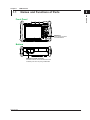
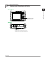
Names and Functions of Parts
1
USB Interface
2
Front Panel
3
4
SETUP key
Press this key to select
the USB interface.
5
Bottom
App
Index
USB type B (mini B) connector
Connector used to connect the AQ1100 to the
controller (such as a PC) using a USB cable.
IM AQ1100-17EN
1-1
1.2
USB Interface Functions and Specifications
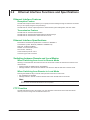
USB Interface Functions and Specifications
Reception Function
You can specify the same settings as those specified by front panel key operations.
Receives output requests for measured data, setup data of the panel, and error codes.
Transmission Function
Outputs measured and computed data.
Outputs panel setup data and the status byte.
Outputs error codes that have occurred.
USB Interface Specifications
Electrical and mechanical specifications:
Connector:
Number of ports:
Power supply:
Compatible PC systems:
Conforms to USB Rev.1.1
Type B (mini B) connector (receptacle)
1
Self-powered
PC running Windows 2000, Windows XP, or Windows Vista with a standard USB port (a separate device driver is needed to connect to a PC).
Switching between Remote and Local Modes
When Switching from Local to Remote Mode
Sending a command when the instrument is in the local mode causes the instrument to switch to the
remote mode.
• All keys except the Local soft key are disabled.
• Settings entered in local mode are retained even when the AQ1100 switches to remote mode.
When Switching from Remote to Local Mode
Pressing the Local soft key in remote mode puts the instrument in local mode.
• Key operations are enabled.
• Settings entered in remote mode are retained even when the AQ1100 switches to local mode.
Note
The AQ1100 cannot be remotely controlled via the USB interface while the storage function is in operation.
Remote control via the Ethernet interface is also not possible.
1-2
IM AQ1100-17EN
1.3
Connecting via the USB Interface
1
USB Interface
2
Connection Procedure
1.Open the bottom cover of the left side.
2.Connect a USB cable to the type B (mini B) connector.
3
4
5
Bottom
Precautions to Be Taken When Connecting the Cable
• Connect the USB cable by inserting the connector firmly into the USB connector.
• Do not connect or disconnect the USB cable after the power is turned ON until the AQ1100 series is
ready for operation (approximately 20 s).
IM AQ1100-17EN
1-3
App
Index
1.4
Setting the AQ1100 (USB)
Procedure
Selecting the USB Interface Function
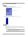
1.Press SETUP and then the System Setup soft key to display the following screen.
Set the mode to Control I/O.
Releasing the Remote Control
1.Press the Local soft key that appears on the screen after communication starts.
Explanation
USB Interface
To control the AQ1100 remotely using communication commands through the USB port, install
YOKOGAWA’s TMC (Text and Measurement Class) driver into your PC. To obtain YOKOGAWA’s USB
TMC driver, contact your nearest YOKOGAWA dealer or access the following USB driver page at our
Web site and download it.
http://www.yokogawa.com/tm/tm-softdownload.htm
Note
• You cannot change the display while the AQ1100 is being remotely controlled.
• Only use the USB TMC driver (or software) provided by YOKOGAWA.
1-4
IM AQ1100-17EN
Chapter 2 2.1
Ethernet Interface (Option)
Names and Functions of Parts
1
2
Front Panel
Ethernet Interface (Option)
3
4
SETUP key
Press this key to select
the ethernet interface.
5
Bottom
App
Index
Ethernet Port
Connector used to connect the AQ1100 to the
controller (such as a PC) using a ethernet cable.
IM AQ1100-17EN
2-1
2.2
Ethernet Interface Functions and Specifications
Ethernet Interface Features
Reception Feature
The AQ1100 reception feature allows you to specify the same settings through an Ethernet connection
that you can specify using the front panel keys.
The AQ1100 can receive output requests for measured data, panel setting data, and error codes.
Transmission Feature
The AQ1100 can transmit measured data.
The AQ1100 can transmit panel setting data and the status byte.
The AQ1100 can transmit error codes when errors occur.
Ethernet Interface Specifications
Electrical and mechanical specifications: Conforms to IEEE802.3
Transmission system: Ethernet (10BASE-T/100BASE-TX)
Data rate: 10 Mbps/100 Mbps
Number of communication ports: 1
Port number: 10001/tcp
Communication protocol: VXI-11
Connector type: RJ45 connector
Switching between Remote and Local Modes
When Switching from Local to Remote Mode
Sending a command when the instrument is in the local mode causes the instrument to switch to the
remote mode.
• All keys except the Local soft key are disabled.
• Settings entered in local mode are retained even when the AQ1100 switches to remote mode.
When Switching from Remote to Local Mode
Pressing the Local soft key in remote mode puts the instrument in local mode.
• Key operations are enabled.
• Settings entered in remote mode are retained even when the AQ1100 to local mode.
Note
The AQ1100 cannot be remotely controlled via the USB interface while the storage function is in operation.
Remote control via the Ethernet interface is also not possible.
FTP Function
The AQ1100 series has an FTP function. You can transfer the data stored in the AQ1100 internal
memory to the PC using FTP commands from the PC.
2-2
IM AQ1100-17EN
2.3
Connecting the Ethernet Interface
1
2
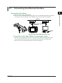
Connection Procedure
Ethernet Interface (Option)
1.Open the bottom cover of the right side.
2.Connect a UTP (Unshielded Twisted-Pair) cable or an STP (Shielded Twisted-Pair) cable that is
connected to a hub, for example, to the 100BASE-TX port on the bottom of the AQ1100.
3
Ethernet
*
Hub or router supporting
100BASE-TX
4
*
5
Bottom
AQ1100
PC
Network
NIC
App
* UTP cable or STP cable (straight cable in either case)
Precautions to Be Taken When Connecting the Cable
Index
• Be sure to use a straight cable via a hub for the connection between the AQ1100 and the PC.
• Use a network cable that conforms to your network environment (such as the data rate).
• When using a UTP cable (straight cable), use a cable of category 5.
IM AQ1100-17EN
2-3
2.4
Setting the AQ1100 (Network)
The settings for remotely controlling the AQ1100 via the Ethernet interface are explained below.
Procedure
Selecting the Ethernet Interface Function
1.Press SETUP and then the System Setup soft key to display the following screen.
Set the Ethernet Interface.
Releasing the Remote Control
1.Press the Local soft key that appears on the screen after communication starts.
2-4
IM AQ1100-17EN
2.4 Setting the AQ1100 (Network)
1
Explanation
Setting the Ethernet Interface
You must set the following parameters to use the Ethernet interface function.
2
• Enabling or Disabling the Network Setup
Ethernet Interface (Option)
After you have set the user name, password, timeout value, and TCP/IP parameters, select Valid
and then restart the AQ1100 to use the network connection.
3
• User Name
• Password
• Setting the Timeout Value
The connection to the network is automatically disconnected if there is no access to the AQ1100
for the specified time.
• Setting the TCP/IP
IP Address
Subnet Mask
Default Gateway
4
5
For details on how to configure the settings, see section 10.4, “Configuring Network Settings (Option),”
in the AQ1100 Multi Field Tester OLTS User's Manual, IM AQ1100-01EN.
App
Note
• You must restart the AQ1100 if you change the Ethernet settings. Before you restart the AQ1100, the
settings from before you changed the settings are used.
• The AQ1100 cannot be remotely controlled via the ethernet interface while the USB storage function is in
operation.
IM AQ1100-17EN
2-5
Index
Chapter 3 3.1
Before Programming
Messages
1
Messages
Program Messages
Program Message Unit
A program message consists of zero or more
program message units; each unit corresponds to
one command. The instrument executes the received
commands in order.
Each program message unit is separated by a
semicolon (;).
Example 1.&5FS.0%VMBUJPO.0%@$86/*5%#1.5
Unit
Unit
<PMT>
PMT is a program message terminator. The following
three types are available.
• NL (New Line)
Same as LF (Line Feed). ASCII code"0AH" is used.
• ^END
END message defined in IEEE488.1. (EOI signal)
(The data byte sent with an END message will be
the final item of the program message unit.)
• NL^END
NL with an END message added (NL is not included
in the program message unit.)
Program Header
A program header is used to indicate the command
type. For details, see section 3.2, “Commands.”
IM AQ1100-17EN
Program Data
If certain conditions are required in executing a
command, program data is added. A space (ASCII
code “20H”) separates the program data from the
header. If there are multiple sets of program data, they
are separated by commas (,). For details, see section
3.4, “Data.”
Example 1.&5FS.0%VMBUJPO.0%@$81.5
Header
2
3
Before Programming
Messages are used to exchange information between
the controller and the instrument. Messages that are
sent from the controller to the instrument are called
program messages and messages that are sent
back from the instrument to the controller are called
response messages.
If a program message contains a message unit that
requests a response (a query), the instrument returns
a response message upon receiving the program
message. A single response message is always
returned in response to a single program message.
4
Data
Response Messages
Response Message Units
A response message consists of one or more
response message units: each response message unit
corresponds to one response. Response message
units are delimited by a ";" (semicolon).
5
App
Example 1.&5FS.0%VMBUJPO.0%@$86/*5%#1.5
Unit
Unit
Index
<RMT>
RMT stands for “response message terminator.” The
response message terminator is NL^EOM.
Response Header
A response header sometimes precedes the response
data. A space separates the data from the header. For
details, see section 3.3, “Response.”
Response Data
Response data contains the content of the response.
If there are multiple sets of response data, they are
separated by commas (,). For details, see section 3.4,
“Data.”
Example &3.5 1.&5FS.0%VMBUJPO.0%@$81.5
Data
Header
Data
If there are multiple queries in a program message,
responses are returned in the same order that the
queries were received in. The AQ1100 returns a single
response message unit to most queries, but there
are queries that the AQ1100 returns multiple units to.
The first response message unit always corresponds
to the first query, but the nth response unit may not
necessarily correspond to the nth query. If you want to
make sure that every response is retrieved, divide the
program messages into individual messages.
3-1
3.1 Messages
Note
• It is always possible to send a program message if the
previous message which was sent did not contain any
queries.
• If the previous message contained a query, it is not
possible to send another program message until a
response message has been received. An error will
occur if a program message is sent before a response
message has been received in its entirety. A response
message which has not been receivedwill be discarded.
• If an attempt is made by the controller to receive
a response message, even if there it no response
message, an error will occur. An error will also occur if
the controller makes an attempt to receive a response
message before transmission of a program message has
been completed.
• If a program message of more than one unit is sent
and some of the units are incomplete, this instrument
receives program message units which the instrument
thinks complete and attempts to execute them. However,
these attempts may not always be successful and
a response may not always be returned, even if the
program message contains queries.
3-2
IM AQ1100-17EN
3.2
Commands
Command
There are three types of commands (program headers)
that a controller may send to the DLM2000. The
commands differ in their program header formats.
Common Command Header
Common command example *CLS
Compound Header
Other commands that are specific to the AQ1100 are
classified and arranged in a hierarchy according to
their functions. Be sure to use a colon to specify a
lower hierarchical level.
Compound header example :PMETer:LINK:STATe
When Concatenating Commands
Command Groups
A command group is a group of commands that have
common compound headers arranged in a hierarchy. A
command group may contain sub-groups.
Example
Commands relating to acquisition settings
:PMETer:DREF
:PMETer:LINK:STATe
:PMETer:MAXMin:STATe
:PMETer:MODulation
:PMETer:OFFSet
:PMETer:REFerence
:PMETer:WAVelength:DETail
When Concatenating Commands of the Same
Group
The AQ1100 stores the hierarchical level of the
command that is currently being executed and
processes the next command on the assumption that
it belongs to the same level. Therefore, the common
header section can be omitted for commands that
belong to the same group.
Example
:PMETer:MODulation MOD_CW;UNIT DB<PMT>
When Concatenating Common Commands
Common commands that are defined in the IEEE
488.2-1987 are independent of hierarchy. There is no
need to use a colon.
Example
:PMETer:MODulation MOD_CW;*CLS;UNIT
DB<PMT>
When Separating Commands with <PMT>
If a terminator is used to separate two commands,each
command is a separate message. Therefore,
the common header must be typed in for each
commandeven when commands of the same command
groupare being concatenated.
Example
:PMETer:MODulation MOD_CW<PMT>:PMETer
UNIT DB<PMT>
3
4
5
App
Upper-level Query
An upper-level query is a query that is made by
appending a question mark to the highest level
command of a group. The controller can receive all
of the settings in a group collectively by executing
an upper-level query. Some upper-level queries of a
group, which may be comprised of more than three
hierarchical levels, can cause the AQ1100 to transmit
all the lower level settings.
Example
:NETWork:CONTrol?<PMT> -> :NETW:CONT:
PASS "ABC";TIM 30;USER "anonyumous"
Note
• The response to an upper-level query can be sent back
to the AQ1100 as a program message. This enables the
settings that were present when the upper-level query
was made to be reproduced later on.
• Some upper-level queries do not return setup data that is
not currently in use. Exercise caution because not all of a
group’s information is necessarily returned in a response.
When Concatenating Commands of Different
Groups
If the subsequent command does not belong to the same
group, place a colon in front of the header (cannot be omitted).
Example
:PMETer:MODulation MOD_CW;:MENU:
FUNCtion TOP<PMT>
IM AQ1100-17EN
2
Before Programming
Commands that are defined in IEEE 488.2-1987 are
called common commands. Be sure to include an
asterisk (*) at the beginning of a common command.
1
3-3
Index
3.2 Commands
Header Interpretation Rules
The AQ1100 interprets the header that it receives
according to the rules below.
Example
"DRANge" can be written as "drange" or "Drange."
• The lower-case characters can be omitted.
Example
"DRANge" can be written as "DRANG" or "DRAN."
• The question mark at the end of a header indicates
that it is a query. You cannot omit the question mark.
Example
The shortest abbreviation for "DRANge?" is "DRAN?."
• If the <x> (value) at the end of a mnemonic is
omitted, it is interpreted as a 1.
Example
If you write "M" for "M<x>, " "M1." is specified.
Note
A mnemonic is a character string made up of
alphanumeric characters.)
3-4
IM AQ1100-17EN
3.3
Response
1
Form
2
When the controller sends a query with a question
mark, the AQ1100 returns a response message to the
query.
3
Response Consisting of a Header and Data
Before Programming
Responses that can be used as program messages
without any changes are returned with command
headers attached.
Example
:PMETer:MODulation?<PMT> -> :PMETer:MODulation MOD_270HZ<RMT>
4
5
If You Want the AQ1100 to Return Responses
without Headers
You can configure the AQ1100 so that even responses
that have both headers and data are returned without
headers. Use the COMMunicate:HEADer command for
this purpose.
App
Abbreviated Form
Index
The AQ1100 normally returns response headers with
the lower-case section removed. You can configure
the AQ1100 so that full headers are returned. Use the
COMMunicate:VERBose command for this purpose.
IM AQ1100-17EN
3-5
3.4
Data
Data contains conditions and values that are written
after the header. A space separates the data from the
header. Data is grouped as follows:
Data
<Decimal>
<Distance><Time>
<Wavelength><Loss>
<Character data>
<Boolean>
<String data>
Description
A value expressed in decimal notation
(Example: Western calendar year
->MISC:DATE:YEAR 2009)
A physical value
(Example: Timeout value ->NETWork: CONTrol:TIMeout 30))
Predefined character string (mnemonic). Select from the available strings in braces.
(Example: Select the function mode
->MENU:FUNCtion {TOP|LSPM|LOSStest
|PONPm|MLOSstest|IPTest})
Indicates ON and OFF. Specify ON or OFF.
(Example: Turn on the DHCP ->NETWork:
DHCP ON))
User-defined string
(Example: Set the Network password
->NETWork:CONTrol:PASSword "ABC")
<Distance>, <Time>, <Wavelength>, and
<Loss>
<Distance>, <Time>, <Wavelength>, and <Loss>
indicate decimal values that have physical significance.
A <Multiplier> or <Unit> can be attached to the <NRf>
form that was described earlier. The following types of
expressions are possible.
Form
<NRf><Multiplier><Unit>
<NRf><Unit>
<NRf><Multiplier>
<NRf>
<Multiplier>
<Multipliers> that you can use are indicated in the
following table.
Symbol
EX
PE
T
G
MA
K
M
U
N
P
F
A
<Decimal>
<Decimal> indicates a value expressed as a decimal
number, as shown in the table below. Decimal values are
written in the NR form as specified in ANSI X3.42-1975.
Symbol
<NR1>
<NR2>
<NR3>
<NRf>
Description
Example
Integer
125 –1
Fixed point number
125.0
–.90
Floating point number 125.0E+0 –9E–1
Any of the forms <NR1> to <NR3> is allowed.
+1000
+001.
+.1E4
• The AQ1100 can receive decimal values that are
sent from the controller in any form, from <NR1> to
<NR3>. This is expressed as <NRf>.
• The AQ1100 returns a response to the controller in
one of the forms from <NR1> to <NR3> depending
on the query. The same form is used regardless of
the size of the value.
• For the <NR3> form, the plus sign after the “E” can
be omitted. You cannot omit the minus sign.
• If a value outside the setting range is entered, the
value is adjusted to the closest value within the
range.
• If a value has more significant digits than are
available, the value will be rounded.
3-6
Example
0.85UM
500m
5M
5E -3
Word
Exa
Peta
Tera
Giga
Mega
Kilo
Milli
Micro
Nano
Pico
Femto
Atto
Description
1018
1015
1012
109
106
103
10–3
10–6
10–9
10–12
10–15
10–18
<Unit>
<Units> that you can use are indicated in the following
table.
Symbol
M
S
dB
UM
•
•
•
•
Word
Meter
Second
Decibel
Micro meter
Description
Distance
Time
Level
Wavelength
<Multiplier> and <Unit> are not case sensitive.
“U” is used to indicate micro (“μ”).
“MA” is used for Mega to distinguish it from Milli.
If both <Multiplier> and <Unit> are omitted, the
default unit is used.
IM AQ1100-17EN
3.4 Data
1
<Character Data>
<Character data> is a predefined character string
(mnemonics). It is mainly used to indicate that an
option listed as a character string in braces must be
selected and entered. The data interpretation rules are
the same as those described in “Header Interpretation
Rules” on page 3-4.
Form
{SIMPLE|DETAIL|WIZARD|MULTI}
2
3
Example
DETAIL
Before Programming
• As with the header, the COMMunicate:VERBose
command can be used to select whether to return
the response in the full form or in the abbreviated
form.
• The COMMunicate:HEADer setting does not affect
<character data>.
4
5
<Boolean>
<Boolean> is data that indicates ON or OFF. The
following types of expressions are possible.
Form
{ON|OFF|<NRf>}
Example
ON
OFF
1
App
0
• When <Boolean> is expressed in the <NRf> form,
“OFF” is selected if the rounded integer value is 0,
and ON is selected for all other cases.
• A response message is always returned with a 1 if
the value is ON and with a 0 if the value is OFF.
Index
<String Data>
<String data> is not a predefined character string like
<character data>. It can be any character string. The
character string must be enclosed in single quotation
marks (') or double quotation marks (").
Form
Example
<Character string data> 'ABC' "IEEE488.2-1987"
• If a character string contains a double quotation
mark ("), the double quotation mark is expressed as
two consecutive quotation marks (""). This rule also
applies to single quotation marks.
• A response message is always enclosed in double
quotation marks (").
• <String data> is any character string. Therefore,
the AQ1100 assumes that the remaining program
message units are part of the character string
if no single (') or double quotation mark (") is
encountered. As a result, no error is detected if a
quotation mark is omitted.
IM AQ1100-17EN
3-7
Chapter 4
4.1
Commands
List of Commands
Command
COMMunicate Group
:COMMunicate?
:COMMunicate:HEADer
:COMMunicate:VERBose
:LIGHtsource:ABORt
:LIGHtsource:EXECute
:LIGHtsource:MODulation
:LIGHtsource:WAVelength
MENU Group
:MENU:ERRor:CLEar
:MENU:FUNCtion
MISC Group
:MISC:ALARmsound
:MISC:BRIGhtness:AC
:MISC:BRIGhtness:BATTery
:MISC:BACKlightoff
:MISC:DATE:DAY
:MISC:DATE:GET?
:MISC:DATE:HOUR
:MISC:DATE:MINute
:MISC:DATE:MODE
:MISC:DATE:MONTh
:MISC:DATE:SECond
:MISC:DATE:SET
:MISC:DATE:YEAR
:MISC:LANGuage
:MISC:POWersave:AC
:MISC:POWersave:BATTery
NETWork Group
:NETWork:CONTrol:PASSword
:NETWork:CONTrol:TIMeout
:NETWork:CONTrol:USERname
:NETWork:DHCP
:NETWork:GATeway
:NETWork:IPADdress
:NETWork:NETMask
:NETWork:STATe
IM AQ1100-17EN
Function
Page
Queries all communication settings.
Sets or queries whether or not a header is added to the response to a query.
(Example with header: PMETer:REFerence 5.00. Example without header:
5.00.)
Sets or queries whether the response to a query is returned fully spelled out
(example: PMETer:REFerence 5.00) or using abbreviation (example: PMET:
REF 5.00).
4-4
4-4
Turns the measurement light off.
Turns the measurement light on.
Sets or queries the light source modulation frequency.
Sets or queries the light source wavelength.
4-5
4-5
4-5
4-5
Clears the error dialog box.
Sets or queries the function mode.
4-6
4-6
Sets or queries the alarm sound.
Sets or queries the LCD brightness when the AC adapter is connected.
Sets or queries the LCD brightness when the AQ1100 is running on battery
power.
Sets or queries the backlight off setting when the AQ1100 is running on battery
power.
Sets or queries the day.
Queries the date and time.
Sets or queries the hour.
Sets or queries the minute.
Sets or queries the date display type.
Sets or queries the month.
Sets or queries the second.
Applies the date and time change.
Sets or queries the year.
Sets or queries the language.
Sets or queries the power-save setting when the AC adapter is connected.
Sets or queries the power-save setting when the AQ1100 is running on battery
power.
4-7
4-7
4-7
Sets or queries the password.
Sets or queries the timeout value.
Sets or queries the user name.
Sets or queries the DHCP on/off state.
Sets or queries the gateway.
Sets or queries the IP address.
Sets or queries the subnet mask.
Sets or queries the Ethernet on/off state.
4-9
4-9
4-9
4-9
4-9
4-9
4-10
4-10
2
3
4-4
4
Commands
LIGHtsource Group
1
5
付
索
4-7
4-7
4-7
4-7
4-7
4-7
4-7
4-8
4-8
4-8
4-8
4-8
4-8
4-1
4.1 A List of Commands
Command
PMETer Group
:PMETer:AVERage:TIMes
:PMETer:DREF
:PMETer:LINK:STATe
:PMETer:MAXMin:STATe
:PMETer:MAXMin:MAX?
:PMETer:MAXMin:MIN?
:PMETer:MEASurement:DATA?
:PMETer:MODulation
:PMETer:OFFSet
:PMETer:REFerence
:PMETer:THReshold:LOWer
:PMETer:THReshold:UPPer
:PMETer:UNIT
:PMETer:WAVelength:DETail
:PMETer:ZERoset
PON Group
:PON:AVERage:TIMes
:PON:DIRection
:PON:M1310:MEASurement:DATA?
:PON:M1310:OFFSet
:PON:M1310:THReshold:JUDGe?
:PON:M1310:THReshold:LOWer
:PON:M1310:THReshold:UPPer
:PON:M1490:MEASurement:DATA?
:PON:M1490:OFFSet
:PON:M1490:THReshold:JUDGe?
:PON:M1490:THReshold:LOWer
:PON:M1490:THReshold:UPPer
:PON:M1550:MEASurement:DATA?
:PON:M1550:OFFSet
:PON:M1550:THReshold:JUDGe?
:PON:M1550:THReshold:LOWer
:PON:M1550:THReshold:UPPer
:PON:UNIT
:PON:ZERoset
PRINt Group
:PRINt:COLor
:PRINt:EXECute
:PRINt:MAKer
SETup Group
:SETup:INITialize
STATus Group
:STATus?
:STATus:CONDition?
:STATus:ERRor?
:STATus:QENable
:STATus:QMESsage
SYSTem Group
:SYSTem:REBoot
:SYSTem:SHUTdown
4-2
Function
Page
Sets or queries the power meter average count.
Executes Dref on the power meter.
Sets or queries the light source power meter setting interlock.
Sets or queries the MAX and MIN display on/off state.
Sets or queries the maximum value.
Sets or queries the minimum value.
Queries the power meter’s measured results.
Sets or queries the power meter modulation.
Sets or queries the power meter offset.
Sets or queries the power meter reference value.
Sets or queries the power meter lower threshold value.
Sets or queries the power meter upper threshold value.
Sets or queries the power meter display unit.
Sets or queries the wavelength when the wavelength mode is set to Detail.
Executes zero set on the power meter.
4-11
4-11
4-11
4-11
4-11
4-11
4-11
4-11
4-11
4-11
4-11
4-12
4-12
4-12
4-12
Sets or queries the PON power meter average count.
Sets or queries the PON power meter wavelength.
Queries the measured results of the 1310 nm PON power meter.
Sets or queries the 1310 nm PON power meter offset.
Queries the threshold judgment results of the 1310 nm PON power meter.
Sets or queries the lower threshold value of the 1310 nm PON power meter.
Sets or queries the upper threshold value of the 1310 nm PON power meter.
Queries the measured results of the 1490 nm PON power meter.
Sets or queries the 1490 nm PON power meter offset.
Queries the threshold judgment results of the 1490 nm PON power meter.
Sets or queries the lower threshold value of the 1490 nm PON power meter.
Sets or queries the upper threshold value of the 1490 nm PON power meter.
Queries the measured results of the 1550 nm PON power meter.
Sets or queries the 1550 nm PON power meter offset.
Queries the threshold judgment results of the 1550 nm PON power meter.
Sets or queries the lower threshold value of the 1550 nm PON power meter.
Sets or queries the upper threshold value of the 1550 nm PON power meter.
Sets or queries the PON power meter display unit.
Executes zero set on the PON power meter.
4-13
4-13
4-13
4-13
4-13
4-13
4-13
4-13
4-13
4-13
4-13
4-14
4-14
4-14
4-14
4-14
4-14
4-14
4-14
Sets or queries the print colors.
Executes printing.
Sets or queries the printer manufacturer.
4-15
4-15
4-15
Returns all settings to their factory defaults.
4-16
Queries all the settings for the communication status feature.
Queries the contents of the condition register.
Queries the error code and message information (top of the error queue).
Sets or queries whether or not messages other than errors will be stored to the
error queue (on/off).
Sets or queries whether or not message information will be attached to the
response to the STATus:ERRor? query (on/off).
4-17
4-17
4-17
4-17
Restarts the AQ1100.
Shuts down the AQ1100.
4-18
4-18
4-17
IM AQ1100-17EN
4.1 A List of Commands
Command
VLS Group
:VLS:ABORt
:VLS:EXECute
Common Commands
*CLS (Clear Status)
*SRE (Service Request Enable)
*STB? (Read Status Byte)
*TST? (Self Test)
Page
Turns the visible light source off.
Turns the visible light source on.
4-19
4-19
Clears all event status registers that are displayed in the status byte register
summary.
Sets or queries the standard event enable register.
4-20
Queries and clears the standard event status register.
4-20
Queries the instrument type and firmware version.
Queries the option information.
Returns all the settings except the communication settings to their factory
default values.
Sets or queries the service request enable register.
Queries the current status byte register value.
Executes a self-test.
4-20
4-20
4-20
4-20
4-21
4-21
4-21
1
2
3
4
Commands
*ESE (Standard Event Status
Enable)
*ESR? (Standard Event Status
Register)
*IDN? (Identification)
*OPT? (Option)
*RST (Reset)
Function
5
付
索
IM AQ1100-17EN
4-3
4.2
COMMunicate Group
The commands in this group deal with communications. There are no front panel keys that correspond to the
commands in this group.
:COMMunicate?
Function Queries all communication settings.
:COMMunicate?
Syntax
Example :COMMUNICATE? -> :COMMUNICATE:HEADER
1;VERBOSE 0
:COMMunicate:HEADer
Function
Sets or queries whether or not a header is added
to the response to a query. (Example with header:
PMETer:REFerence 5.00. Example without header:
5.00.)
:COMMunicate:HEADer {<Boolean>}
Syntax
:COMMunicate:HEADer?
Example :COMMUNICATE:HEADER ON
:COMMUNICATE:HEADER? ->:COMMUNICATE:
HEADER 1
:COMMunicate:VERBose
Function
Sets or queries whether the response to a query
is returned fully spelled out (example: PMETer:
REFerence 5.00) or using abbreviation (example:
PMET:REF 5.00).
:COMMunicate:VERBose {<Boolean>}
Syntax
:COMMunicate:VERBose?
Example :COMMUNICATE:VERBOSE ON
:COMMUNICATE:VERBOSE?
->:COMMUNICATE:VERBOSE 0
4-4
IM AQ1100-17EN
4.3
LIGHtsource Group
1
The commands in this group deal with the light source. You can perform the same operations and make the same
settings and queries that you can by using the front panel.
2
:LIGHtsource:ABORt
Function
Syntax
Example
Turns the measurement light off.
:LIGHtsource:ABORt
:LIGHTSOURCE:ABORT
3
:LIGHtsource:EXECute
4
Turns the measurement light on.
:LIGHtsource:EXECute
:LIGHTSOURCE:EXECUTE
Commands
Function
Syntax
Example
Description Measurement light and visible light cannot be on at
the same time.
5
:LIGHtsource:MODulation
Function
Syntax
Example
Sets or queries the light source modulation
frequency.
:LIGHtsource:MODulation {MOD_CW|
MOD_270HZ|MOD_1KHZ|MODE_2KHZ}
:LIGHtsource:MODulation?
付
索
:LIGHTSOURCE:MODULATION MOD_CW
:LIGHTSOURCE:MODULATION?
-> :LIGHTSOURCE:MODULATION MOD_CW
Description When :LIGHtsource:WAVelength is set to 0.850 um
or 1.300 um, the modulation frequency can only be
set to CW or 270 Hz.
:LIGHtsource:WAVelength
Function
Syntax
Example
Sets or queries the light source wavelength.
:LIGHtsource:WAVelength {<NRf>}
:LIGHtsource:WAVelength?
<NRf> = 0.850um to 1.650um
(850E-9 to 1650E-9)
:LIGHTSOURCE:WAVELENGTH 0.85um
:LIGHTSOURCE:WAVELENGTH 1650E-9
:LIGHTSOURCE:WAVELENGTH 1.650E-6
:LIGHTSOURCE:WAVELENGTH?
-> :LIGHTSOURCE:WAVELENGTH 1550E-09
Description The wavelengths that can be specified vary
depending on the model.
IM AQ1100-17EN
4-5
4.4
MENU Group
The commands in this group are used to set the function or marker mode or query the settings.
:MENU:ERRor:CLEar
Function
Syntax
Example
Clears the error dialog box.
:MENU:ERRor:CLEar
:MENU:ERROR:CLEAR
:MENU:FUNCtion
Function
Syntax
Example
Sets or queries the function mode.
:MENU:FUNCtion {TOP|LSPM|LOSStest|
PONPm|MLOSstest|IPTest}
:MENU:FUNCtion?
:MENU:FUNCTION TOP
:MENU:FUNCTION? -> :MENU:FUNCTION LSPM
Description Top menu:
TOP
Light source power meter: LSPM
Auto loss test:1
LOSStest
PON power meter:2
PONPm
4-6
Multi-core loss test:1
MLOSstest
IPtest:3
IPTest
1 Can only be selected on products whose power
meter suffix code is SPM or HPM.
2 Can only be selected on products whose power
meter suffix code is PON.
3 Can only be selected on products with the LAN
option.
IM AQ1100-17EN
4.5
MISC Group
1
The commands in this group deal with the date, language, and power management. You can make the same settings
and queries that you can by using the front panel.
:MISC:ALARmsound
Function
Syntax
Example
Sets or queries the alarm sound.
:MISC:ALARmsound {<Boolean>}
:MISC:ALARmsound?
:MISC:ALARMSOUND OFF
:MISC:ALARMSOUND?
-> :MISC:ALARMSOUND 1
Function
Syntax
Example
Sets or queries the LCD brightness when the AC
adapter is connected.
:MISC:BRIGhtness:AC {BRIGHT|NORMAL
|DARK}
:MISC:BRIGhtness:AC?
:MISC:BRIGHTNESS:AC NORMAL
:MISC:BRIGHTNESS:AC?
-> :MISC:BRIGHTNESS:AC NORMAL
Description Bright:
Normal:
Power save:
BRIGHT
NORMAL
DARK
:MISC:BRIGhtness:BATTery
Function
Syntax
Example
Sets or queries the LCD brightness when the
AQ1100 is running on battery power.
:MISC:BRIGhtness:BATTery {BRIGHT|
NORMAL|DARK}
:MISC:BRIGhtness:BATTery?
:MISC:BRIGHTNESS:BATTERY NORMAL
:MISC:BRIGHTNESS:BATTERY?
-> :MISC:BRIGHTNESS:BATTERY NORMAL
Description The parameters are the same as those for :MISC:
BRIGhtness:AC.
:MISC:BACKlightoff
Function
Syntax
Example
Sets or queries the backlight off setting when the
AQ1100 is running on battery power.
:MISC:BACKlightoff {<Boolean>}
:MISC:BACKLIGHTOFF ON
:MISC:BACKLIGHTOFF?
-> :MISC:BACKLIGHTOFF 1
:MISC:DATE:DAY
Function
Syntax
Example
Sets or queries the day.
:MISC:DATE:DAY {<NRf>}
<NRf> = 1 to 31 (in steps of 1)
:MISC:DATE:DAY?
:MISC:DATE:DAY 1
:MISC:DATE:DAY? -> :MISC:DATE:DAY 1
Description This setting takes effect when :MISC:DATE:SET is
executed.
IM AQ1100-17EN
:MISC:DATE:GET?
Function
Syntax
Example
Queries the date and time.
:MISC:DATE:GET?
:MISC:DATE:GET?
-> :MISC:DATE:GET 2009/01/31 23:59:59
4
:MISC:DATE:HOUR
Function
Syntax
Example
Sets or queries the hour.
:MISC:DATE:HOUR {<NRf>}
<NRf> = 0 to 23 (in steps of 1)
5
:MISC:DATE:HOUR?
:MISC:DATE:HOUR 17
:MISC:DATE:HOUR?
-> :MISC:DATE:HOUR 12
Description This setting takes effect when :MISC:DATE:SET is
executed.
:MISC:DATE:MINute
Function
Syntax
Example
:MISC:DATE:MINute?
:MISC:DATE:MINUTE 5
:MISC:DATE:MINUTE?
-> :MISC:DATE:MINUTE 59
executed.
:MISC:DATE:MODE
Sets or queries the date display type.
:MISC:DATE:MODE {TYPE1|TYPE2|TYPE3}
:MISC:DATE:MODE?
:MISC:DATE:MODE TYPE1
:MISC:DATE:MODE?
-> :MISC:DATE:MODE TYPE2
Description Date display types
2009/08/29 12:16 TYPE1
08/29/2006 12:16 TYPE2
2009/AUG/29 12:16 TYPE3
:MISC:DATE:MONTh
Function
Syntax
Example
付
索
Sets or queries the minute.
:MISC:DATE:MINute {<NRf>}
<NRf> = 0 to 59 (in steps of 1)
Description This setting takes effect when :MISC:DATE:SET is
Function
Syntax
Example
3
Commands
:MISC:BRIGhtness:AC
2
Sets or queries the month.
:MISC:DATE:MONTh {<NRf>}
<NRf> = 1 to 12
:MISC:DATE:MONTh?
:MISC:DATE:MONTh 8
:MISC:DATE:MONTH? -> MISC:DATE:MONTH 8
Description This setting takes effect when :MISC:DATE:SET is
executed.
4-7
4.5 MISC Group
:MISC:DATE:SECond
Function
Syntax
Example
:MISC:POWersave:BATTery
Sets or queries the second.
:MISC:DATE:SECond {<NRf>}
<NRf> = 0 to 59 (in steps of 1)
Function
Syntax
:MISC:DATE:SECOND 0
:MISC:DATE:SECOND?
-> :MISC:DATE:SECOND 0
Description This setting takes effect when :MISC:DATE:SET is
executed.
Description The parameters are the same as those for :MISC:
:MISC:DATE:SET
Function
Syntax
Example
Example
Sets or queries the power-save setting when the
AQ1100 is running on battery power.
:MISC:POWersave:BATTery {OFF|A1MIN|
A5MIN|A10MIN|A30MIN}
:MISC:POWersave:BATTery?
:MISC:POWERSAVE:BATTERY A1MIN
:MISC:POWERSAVE:BATTERY? -> :MISC:
POWERSAVE:BATTERY OFF
POWersave:AC.
Applies the date and time change.
:MISC:DATE:SET
:MISC:DATE:SET
:MISC:DATE:YEAR
Function
Syntax
Example
Sets or queries the year.
:MISC:DATE:YEAR {<NRf>}
<NRf> = 2009 to 2035 (in steps of 1)
:MISC:DATE:YEAR?
:MISC:DATE:YEAR 2009
:MISC:DATE:YEAR? -> :MISC:DATE:YEAR
2009
Description This setting takes effect when :MISC:DATE:SET is
executed.
:MISC:LANGuage
Function
Syntax
Example
Sets or queries the language.
:MISC:LANGuage {JAPANESE|ENGLISH}
:MISC:LANGuage?
:MISC:LANGUAGE ENGLISH
:MISC:LANGUAGE? -> :MISC:LANGUAGE
ENGLISH
:MISC:POWersave:AC
Function
Syntax
Example
Sets or queries the power-save setting when the AC
adapter is connected.
:MISC:POWersave:AC {OFF|A1MIN|A5MIN|A10
MIN|A30MIN}
:MISC:POWersave:AC?
:MISC:POWERSAVE:AC A1MIN
:MISC:POWERSAVE:AC? -> :MISC:POWERSAVE:
AC OFF
Description Disable:
Power save after 1 minute:
Power save after 5 minutes:
Power save after 10 minutes:
Power save after 30 minutes:
4-8
OFF
A1MIN
A5MIN
A10MIN
A30MIN
IM AQ1100-17EN
4.6
NETWork Group
1
The commands in this group can only be used on models with the /LAN option.
:NETWork:CONTrol:PASSword
Function
Syntax
Example
Sets or queries the password.
:NETWork:CONTrol:PASSword <character string>
:NETWORK:CONTROLl:PASSWORD "ABC"
:NETWORK:CONTROLl:PASSWORD?
-> :NETWORK:CONTROLl:PASSWORD "ABC"
Description You cannot use this command if NETWork:STATe is
:NETWork:CONTrol:TIMeout
Function
Syntax
Example
IM AQ1100-17EN
set to OFF.
The setting specified by this command takes effect
when the AQ1100 is restarted. You can restart the
AQ1100 by using :SYSTem:REBoot.
set to OFF.
You cannot use this command if NETWork:DHCP is
set to OFF.
The setting specified by this command takes effect
when the AQ1100 is restarted. You can restart the
AQ1100 by using :SYSTem:REBoot.
Sets or queries the IP address.
:NETWork:IPADdress <character string>
:NETWork:IPADdress?
:NETWORK:IPADDRESS "192.168.0.1"
:NETWORK:IPADDRESS? -> :NETWORK:
IPADDRESS "192.168.0.1"
Description You cannot use this command if NETWork:STATe is
5
索
:NETWork:IPADdress
Function
Syntax
Example
4
付
Sets or queries the gateway.
:NETWork:GATeway <character string>
:NETWork:GATeway?
:NETWORK:GATEWAY "255.255.255.0"
:NETWORK:GATEWAY? -> :NETWORK:
GATEWAY "255.255.255.0"
Description You cannot use this command if NETWork:STATe is
Description You cannot use this command if NETWork:STATe is
set to OFF.
The setting specified by this command takes effect
when the AQ1100 is restarted. You can restart the
AQ1100 by using :SYSTem:REBoot.
3
:NETWork:GATeway
set to OFF.
The setting specified by this command takes effect
when the AQ1100 is restarted. You can restart the
AQ1100 by using :SYSTem:REBoot.
Sets or queries the user name.
:NETWork:CONTrol:USERname <character string>
:NETWORK:CONTROL:USERNAME "anonymous"
:NETWORK:CONTROL:USERNAME?
-> :NETWORK:CONTROL:USERNAME
"anonyumous"
Sets or queries the DHCP on/off state.
:NETWork:DHCP <Boolean>
:NETWork:DHCP?
:NETWORK:DHCP ON
:NETWORK:DHCP? -> :NETWORK:DHCP 1
Description Invalid:OFF or 0
Valid: ON or 1
You cannot use this command if NETWork:STATe is
Function
Syntax
Example
:NETWork:CONTrol:USERname
Function
Syntax
Example
Example
Sets or queries the timeout value.
:NETWork:CONTrol:TIMeout
{<NRf>|INFinite}
:NETWork:CONTrol:TIMeout?
<NRf>: 1 to 3600
:NETWORK:CONTROL:TIMEOUT 30
:NETWORK:CONTROL:TIMEOUT?
-> :NETWORK:CONTROL:TIMEOUT 30
Description The unit is seconds.
You cannot use this command if NETWork:STATe is
Function
Syntax
Commands
set to OFF.
The setting specified by this command takes effect
when the AQ1100 is restarted. You can restart the
AQ1100 by using :SYSTem:REBoot.
You do not have to set the password when the user
name is “anonymous.”
2
:NETWork:DHCP
set to OFF.
You cannot use this command if NETWork:DHCP is
set to OFF.
The setting specified by this command takes effect
when the AQ1100 is restarted. You can restart the
AQ1100 by using :SYSTem:REBoot.
4-9
4.6 NETWork Group
:NETWork:NETMask
Function
Syntax
Example
Sets or queries the subnet mask.
:NETWork:NETMask <character string>
:NETWork:NETMask?
:NETWORK:NETMASK "255.255.255.0"
:NETWORK:NETMASK? -> :NETWORK:
NETMASK "255.255.255.0"
Description You cannot use this command if NETWork:STATe is
set to OFF.
You cannot use this command if NETWork:DHCP is
set to OFF.
The setting specified by this command takes effect
when the AQ1100 is restarted. You can restart the
AQ1100 by using :SYSTem:REBoot.
:NETWork:STATe
Function
Syntax
Example
Sets or queries the Ethernet on/off state.
:NETWork:STATe <Boolean>
:NETWork:STATe?
:NETWORK:STATE ON
:NETWORK:STATE? -> :NETWORK:STATE 1
Description Invalid:OFF or 0
Valid: ON or 1
The setting specified by this command takes effect
when the AQ1100 is restarted. You can restart the
AQ1100 by using :SYSTem:REBoot.
4-10
IM AQ1100-17EN
4.7
PMETer Group
1
The commands in this group deal with the power meter. You can make the same settings and queries that you can by
using the front panel.
:PMETer:AVERage:TIMes
Function
Syntax
Example
Sets or queries the power meter average count.
:PMETer:AVERage:TIMes <T1|T10|T50|T100>
:PMETer:AVERage:TIMes?
:PMETER:AVERAGE:TIMES T1
:PMETER:AVERAGE:TIMES? -> :PMETER:
AVERAGE:TIMES T1
1
T10: 10
T50: 50
T100: 100
:PMETer:DREF
Function
Syntax
Example
Executes Dref on the power meter.
:PMETer:DREF
:PMETer:DREF
:PMETer:LINK:STATe
Function
Syntax
Example
Sets or queries the light source power meter setting
interlock.
:PMETer:LINK:STATe {<Boolean>}
:PMETER:LINK:STATE ON
:PMETER:LINK:STATE?
-> :PMETER:LINK:STATE 1
:PMETer:MAXMin:STATe
Function
Syntax
Example
Sets or queries the MAX and MIN display on/off
state.
:PMETer:MAXMin:STATe {<Boolean>}
:PMETER:MAXMIN:STATE ON
:PMETER:MAXMIN:STATE?
-> :PMETER:MAXMIN:STATE 1
:PMETer:MAXMin:MAX?
Function
Syntax
Example
Sets or queries the maximum value.
:PMETer:MAXMin:MAX?
Function
Syntax
Example
Function
Syntax
Example
3
Sets or queries the power meter modulation.
:PMETer:MODulation {MOD_270HZ|MOD_CW
|MOD_1KHZ|MOD_2KHZ}
:PMETER:MODULATION MOD_270HZ
:PMETER:MODULATION?
-> :PMETER:MODULATION MOD_270HZ
Description You cannot use this command on products whose
power meter suffix code is "PPM".
Function
Syntax
Example
Sets or queries the power meter offset.
:PMETer:OFFSet {<NRf>}
:PMETer:OFFSet?
<NRf> = -9.900 to 9.900 (in steps of 0.001)
5
付
索
:PMETER:OFFSET -5.000
:PMETER:OFFSET?
-> :PMETER:OFFSET -3.000
:PMETer:REFerence
Function
Syntax
Example
Sets or queries the power meter reference value.
:PMETer:REFerence {<NRf>}
:PMETer:REFerence?
<NRf> = -70.00 to 5.00 (in steps of 0.001) [dBm]
:PMETER:REFERENCE 0.00
:PMETER:REFERENCE?
-> :PMETER:REFERENCE 0.00
:PMETer:THReshold:LOWer
Function
MAXMin:STATe is set to ON.
Example
Sets or queries the power meter lower threshold
value.
:PMETer:THReshold:LOWer {<NRf>}
<NRf> = -70.00 to 5.00 (in steps of 0.001) [dBm]
:PMETER:THRESHOLD:LOWER -70.00
:PMETER:THRESHOLD:LOWER?
-> :PMETER:THRESHOLD:LOWER -70.00
Sets or queries the minimum value.
:PMETer:MAXMin:MIN?
:PMETER:MAXMIN:MIN? -> :PMETER:MAXMIN:
MIN? -5.00
Description You can only make this query when :PMETer:
MAXMin:STATe is set to ON.
IM AQ1100-17EN
4
:PMETer:OFFSet
Syntax
:PMETer:MAXMin:MIN?
Queries the power meter’s measured results.
:PMETer:MEASurement:DATA?
:PMETER:MEASUREMENT:DATA?
-> :PMETER:MEASUREMENT:DATA 26.56
:PMETer:MODulation
:PMETER:MAXMIN:MAX? -> :PMETER:MAXMIN:
MAX? 5.00
Description You can only make this query when :PMETer:
Function
Syntax
Example
:PMETer:MEASurement:DATA?
Commands
Description T1:
2
4-11
4.7 PMETer Group
:PMETer:THReshold:UPPer
Function
Syntax
Example
Sets or queries the power meter upper threshold
value.
:PMETer:THReshold:UPPer {<NRf>}
<NRf> = -70.00 to 5.00 (in steps of 0.001) [dBm]
:PMETER:THRESHOLD:UPPER -70
:PMETER:THRESHOLD:UPPER?
-> :PMETER:THRESHOLD:UPPER -70
:PMETer:UNIT
Function
Syntax
Example
Sets or queries the power meter display unit.
:PMETer:UNIT {DB|DBM|W}
:PMETer:UNIT ?
:PMETER:UNIT DBM
:PMETER:UNIT ? -> :PMETER:UNIT DB
:PMETer:WAVelength:DETail
Function
Syntax
Example
Sets or queries the wavelength when the wavelength
mode is set to Detail.
:PMETer:WAVelength:DETail {<NRf>}
:PMETer:WAVelength:DETail?
<NRf> = 0.850um to 1.650um
(850E-9 to 1650E-9)
:PMETer:WAVELENGTH:DETAIL 0.85um
:PMETer:WAVELENGTH:DETAIL 1650E-9
:PMETer:WAVELENGTH:DETAIL 1.650E-6
:PMETer:WAVELENGTH:DETAIL?
-> PMETER:WAVELENGTH:DETAIL 1550E-09
Description If the wavelength mode is set to Simple or CWDM,
executing this command sets the mode to Detail.
:PMETer:ZERoset
Function
Syntax
Example
4-12
Executes zero set on the power meter.
:PMETer:ZERoset
:PMETER:ZEROSET
IM AQ1100-17EN
4.8
PON Group
1
The commands in this group deal with the power meter. These commands are valid when the PON option is selected.
You can make the same settings and queries that you can by using the front panel.
:PON:AVERage:TIMes
:PON:M1310:THReshold:UPPer
Syntax
Syntax
Function
Example
Sets or queries the PON power meter average
count.
:PON:AVERage:TIMes <T1|T10|T50|T100>
:PON:AVERage:TIMes?
:PON:DIRection
Function
Syntax
Example
Sets or queries the PON power meter wavelength.
:PON:DIRection {ONT2OLT|OLT2ONU}
:PON:DIRECTION ONT2OLT
:PON:DIRECTION?
-> :PON:DIRECTION ONT2OLT
Example
Sets or queries the upper threshold value of the
1310 nm PON power meter.
:PON:M1310:THReshold:UPPer {<NRf>}
<NRf> = -70.00 to 5.00 (in steps of 0.001) [dBm]
:PON:M1310:THRESHOLD:UPPER -70.00
:PON:M1310:THRESHOLD:UPPER?
-> :PON:M1310:THRESHOLD:UPPER -70.00
:PON:M1490:MEASurement:DATA?
Function
Syntax
Example
Queries the measured results of the 1490 nm PON
power meter.
:PON:MEASurement:DATA?
:PON:MEASUREMENT:DATA?
-> :PON:MEASUREMENT:DATA -26.5
:PON:M1310:MEASurement:DATA?
:PON:M1490:OFFSet
Syntax
Example
Syntax
Function
Queries the measured results of the 1310 nm PON
power meter.
:PON:M1310:MEASurement:DATA?
:PON:M1310:MEASUREMENT:DATA?
-> :PON:M1310:MEASUREMENT:DATA
:PON:M1310:OFFSet
Function
Syntax
Example
Sets or queries the 1310 nm PON power meter
offset.
:PON:M1310:OFFSet {<NRf>}
<NRf> = -9.900 to 9.900 (in steps of
0.001)
:PON:M1310:OFFSET -9.900
:PON:M1310:OFFSET?
-> :PON:M1310:OFFSET -9.900
:PON:M1310:THReshold:JUDGe?
Function
Syntax
Example
Queries the threshold judgment results of the 1310
nm PON power meter.
:PON:M1310:THReshold:JUDGe?
:PON:M1310:THRESHOLD:JUDGE?
-> :PON:M1310:THRESHOLD:JUDGE FAIL
Description A result of PASS or FAIL is returned.
:PON:M1310:THReshold:LOWer
Function
Syntax
Example
Sets or queries the lower threshold value of the 1310
nm PON power meter.
:PON:M1310:THReshold:LOWer {<NRf>}
<NRf> = -70.00 to 5.00 (in steps of 0.001) [dBm]
Function
Example
Sets or queries the 1490 nm PON power meter
offset.
:PON:M1490:OFFSet {<NRf>}
<NRf> = -9.900 to 9.900 (in steps of
0.001)
:PON:M1490:OFFSET -9.900
:PON:M1490:OFFSET?
-> :PON:M1490:OFFSET -9.900
:PON:M1490:THReshold:JUDGe?
Function
Syntax
Example
Queries the threshold judgment results of the 1490
nm PON power meter.
:PON:M1490:THReshold:JUDGe?
:PON:M1490:THRESHOLD:JUDGE?
-> :PON:M1490:THRESHOLD:JUDGE FAIL
Description A result of PASS or FAIL is returned.
:PON:M1490:THReshold:LOWer
Function
Syntax
Example
Sets or queries the lower threshold value of the 1490
nm PON power meter.
:PON:M1490:THReshold:LOWer {<NRf>}
<NRf> = -70.00 to 5.00 (in steps of 0.001) [dBm]
:PON:M1490:THRESHOLD:LOWER -70.00
:PON:M1490:THRESHOLD:LOWER?
-> :PON:M1490:THRESHOLD:LOWER -70.00
:PON:M1310:THRESHOLD:LOWER -70.00
:PON:M1310:THRESHOLD:LOWER?
-> :PON:M1310:THRESHOLD:LOWER -70.00
IM AQ1100-17EN
4-13
3
4
Commands
:PON:AVERAGE:TIMES
:PON:AVERAGE:TIMES? -> :PON:AVERAGE:
TIMES T1
Function
2
5
付
索
4.8 PON Group
:PON:M1490:THReshold:UPPer
Function
Syntax
Example
Sets or queries the upper threshold value of the
1490 nm PON power meter.
:PON:M1490:THReshold:UPPer {<NRf>}
<NRf> = -70.00 to 5.00 (in steps of 0.001) [dBm]
:PON:M1490:THRESHOLD:UPPER -70.00
:PON:M1490:THRESHOLD:UPPER?
-> :PON:M1490:THRESHOLD:UPPER -70.00
:PON:M1550:MEASurement:DATA?
Function
Syntax
Example
Queries the measured results of the 1550 nm PON
power meter.
:PON:M1550:MEASurement:DATA?
:PON:M1550:MEASUREMENT:DATA?
-> :PON:M1550:MEASUREMENT:DATA
:PON:UNIT
Function
Syntax
Example
Sets or queries the PON power meter display unit.
:PON:UNIT {DBM|W}
:PON:UNIT DBM
:PON:UNIT ? -> :PON:UNIT DBM
:PON:ZERoset
Function
Syntax
Example
Executes zero set on the PON power meter.
:PON:ZERoset
:PON:ZEROSET
:PON:M1550:OFFSet
Function
Syntax
Example
Sets or queries the 1550 nm PON power meter
offset.
:PON:M1550:OFFSet {<NRf>}
<NRf> = -9.900 to 9.900 (in steps of
0.001)
:PON:M1550:OFFSET -9.900
:PON:M1550:OFFSET?
-> :PON:M1550:OFFSET -9.900
:PON:M1550:THReshold:JUDGe?
Function
Syntax
Example
Queries the threshold judgment results of the 1550
nm PON power meter.
:PON:M1550:THReshold:JUDGe?
:PON:M1550:THRESHOLD:JUDGE?
-> :PON:M1550:THRESHOLD:JUDGE FAIL
Description A result of PASS or FAIL is returned.
:PON:M1550:THReshold:LOWer
Function
Syntax
Example
Sets or queries the lower threshold value of the 1550
nm PON power meter.
:PON:M1550:THReshold:LOWer {<NRf>}
<NRf> = -70.00 to 5.00 (in steps of
0.001) [dBm]
:PON:M1550:THRESHOLD:LOWER -70.00
:PON:M1550:THRESHOLD:LOWER?
-> :PON:M1550:THRESHOLD:LOWER -70.00
:PON:M1550:THReshold:UPPer
Function
Syntax
Example
4-14
Sets or queries the upper threshold value of the
1550 nm PON power meter.
:PON:M1550:THReshold:UPPer {<NRf>}
<NRf> = -70.00 to 5.00 (in steps of
0.001) [dBm]
:PON:M1550:THRESHOLD:UPPER -70.00
:PON:M1550:THRESHOLD:UPPER?
-> :PON:M1550:THRESHOLD:UPPER -70.00
IM AQ1100-17EN
4.9
PRINt Group
1
The commands in this group deal with printing. You can make the same settings and queries that you can by using the
front panel.
2
:PRINt:COLor
Function
Syntax
Example
Sets or queries the print colors.
:PRINt:COLor {COLOR | BW}
:PRINt:COLor?
3
:PRINT:COLOR COLOR
:PRINT:COLOR? -> :PRINT:COLOR BW
Description Screen colors:
4
COLOR
Black and white: BW
Commands
:PRINt:EXECute
Function
Syntax
Example
5
Executes printing.
:PRINt:EXECute
:PRINT:EXECUTE
:PRINt:MAKer
付
Example
索
Function
Syntax
Sets or queries the printer manufacturer.
:PRINt:MAKer {HP|EPSON|SEIKO}
:PRINt:MAKer?
:PRINT:MAKER HP
:PRINT:MAKER?
-> :PRINT:MAKER EPSON
Description HP inkjet printer:
EPSON inkjet printer:
Seiko Instruments MPU-L465:
IM AQ1100-17EN
HP
EPSON
SEIKO
4-15
4.10 SETup Group
The commands in this group deal with the initialization of the settings. The AQ1100 settings can be returned to their
factory defaults.
:SETup:INITialize
Function
Syntax
Example
4-16
Returns all settings to their factory defaults.
:SETup:INITialize
:SETUP:INITIALIZE
IM AQ1100-17EN
4.11 STATus Group
1
The commands in this group are used to make settings and queries related to the communication status feature. There
are no front panel keys that correspond to the commands in this group.
2
:STATus?
Function
Syntax
Example
Queries all the settings for the communication status
feature.
:STATus?
:STATUS? -> :STATUS:QENABLE1;
QMESSAGE 1
3
4
Function
Syntax
Example
Commands
:STATus:CONDition?
Queries the contents of the condition register.
:STATus:CONDition?
:STATUS:CONDITION? -> 16
5
Description For information about the condition register, see
section 5.1, “Condition Register.”
:STATus:ERRor?
付
Syntax
Example
索
Function
Queries the error code and message information (top
of the error queue).
:STATus:ERRor?
:STATUS:ERROR? ->113,"Undefined header"
:STATus:QENable
Function
Syntax
Example
Sets or queries whether or not messages other than
errors will be stored to the error queue (on/off).
:STATus:QENable {<Boolean>}:STATus:
QENable?
:STATUS:QENABLE ON
:STATUS:QENABLE? -> :STATUS:QENABLE 1
:STATus:QMESsage
Function
Syntax
Example
Sets or queries whether or not message information
will be attached to the response to the STATus:
ERRor? query (on/off).
:STATus:QMESsage {<Boolean>}
:STATus:QMESsage?
:STATUS:QMESSAGE OFF
:STATUS:QMESSAGE? -> :STATUS:QMESSAGE 1
IM AQ1100-17EN
4-17
4.12 SYSTem Group
The commands in this group deal with startup. There are no front panel keys that correspond to the commands in this
group.
:SYSTem:REBoot
Function
Syntax
Example
Restarts the AQ1100.
:SYSTem:REBoot
:SYSTEM:REBOOT
:SYSTem:SHUTdown
Function
Syntax
Example
4-18
Shuts down the AQ1100.
:SYSTem:SHUTdown
:SYSTEM:SHUTDOWN
IM AQ1100-17EN
4.13 VLS Group
1
The commands in this group deal with the visible light source. These commands are valid when the VLS option is
selected. You can perform the same operations and make the same settings and queries that you can by using the
front panel.
2
:VLS:ABORt
Function
Syntax
Example
3
Turns the visible light source off.
:VLS:ABORt
:VLS:ABORT
4
:VLS:EXECute
Turns the visible light source on.
:VLS:EXECute
:VLS:EXECUTE
Commands
Function
Syntax
Example
5
付
索
IM AQ1100-17EN
4-19
4.14 Common Commands
*CLS (Clear Status)
Function
Clears all event status registers that are displayed in
the status byte register summary.
*CLS
*CLS
Syntax
Example
Description • Clears all queues except the output queue and
all event registers except the MAV summary
message.
• After this command is executed, the AQ1100 is
set to OCIS (Operation Complete Command Idle
State) and OQIS (Operation Complete Query Idle
State).
*ESE (Standard Event Status Enable)
Function
Syntax
Example
Sets or queries the standard event enable register.
*ESE<wsp><integer>
*ESE?
<integer> = 0 to 255
*ESE 251
*ESE? -> 251
Description •
•
•
•
Each item whose bit is set is enabled.
The ESE is set to its default value when:
The power is turned on.
Zero is set.
The ESE does not change its value when the
following commands are executed:
*RST
*CLS
Device clear (DCL, SDC)
The default value is zero.
*ESR? (Standard Event Status Register)
Function
Queries and clears the standard event status
register.
*ESR?
*ESR? -> 251
Syntax
Example
Description The returned value of this query is not affected by
the ESE (Event Status Enable Register).
4-20
*IDN? (Identification)
Function
Syntax
Example
Queries the instrument type and firmware version.
*IDN?
*IDN? -> YOKOGAWA,AQ1100,SN123456789,
F1.00
Description Four data fields delimited by commas are returned.
Field 1: Manufacturer
“YOKOGAWA”
Field 2: Model
“AQ1100”
Field 3: Instrument serial number
“SN123456789”
Field 4: Firmware version “F1.00”
*OPT? (Option)
Function Queries the option information.
*OPT?
Syntax
Example *OPT? -> PM,LS,LAN
Description The installed options are returned delimited by
commas.
Power meter:
Light source:
Visible light source:
LAN:
PM
LS
VLS
LAN
*RST (Reset)
Function
Returns all the settings except the communication
settings to their factory default values.
*RST
*RST
Syntax
Example
Description • This command stops the operation in progress
and resets the AQ1100 to its factory defaults.
• The following items do not change:
Output queue
SRE
ESE
Calibration data that affects the AQ1100
specifications
IM AQ1100-17EN
4.14 Common Commands
*SRE (Service Request Enable)
Function
Syntax
Example
1
Sets or queries the service request enable register.
*SRE <wsp><integer>
*SRE?
<integer> = 0 to 255
*SRE 250
*SRE? -> 250
Description •
•
•
Each item whose bit is set is enabled.
The SRE is set to its default value when:
The power is turned on.
Zero is set.
The SRE does not change its value when the
following commands are executed:
*RST
*CLS
Device clear (DCL, SDC)
The default value is zero.
3
4
Commands
•
2
5
*STB? (Read Status Byte)
Function
Syntax
Example
Queries the current status byte register value.
*STB?
*STB? -> 251
付
Description The STB is not cleared even if it is read.
*TST? (Self Test)
Function
Syntax
Example
索
Executes a self-test.
*TST?
*TST? -> 0
Description The AQ1100 returns 0 if the self-test is successful
and 1 if it is not.
IM AQ1100-17EN
4-21
Chapter 5
Condition Register / Output and Error Queue
5.1
Condition Register
1
2
The condition register indicates the internal condition of the instrument.
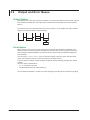
Condition Register
45"5VT$0/%JUJPO
15
14
13
12
0
0
0
0
11
10
9
8
LS PME PMZ PMM
7
6
5
4
3
2
1
0
0
AR
0
FIA
0
FILE
0
0
3
The meaning of each bit of the condition register is as follows:
Bit 2
Bit 4
Bit 6
Bit 8
Bit 9
Bit 10
Bit 11
FILE
FIA
AR
PMM
PMZ
PME
LS
Set to 1 while a file is being accessed.
Set to 1 while checking whether the fiber is in use.
Set to 1 while the auto range measurement is in progress.
Set to 1 while the power meter measurement is in progress.
Set to 1 while the power meter is being reset to zero.
Set to 1 while a measurement error is occurring in the power meter.
Set to 1 while the light source is ON.
4
5
Condition Register / Output and Error Queue
App
Index
IM AQ1300-17EN
5-1
5.2
Output and Error Queue
Output Queue
The output queue stores query response messages. As shown below, data is stored in order and read
from the oldest message first. The output queue is cleared when the AQ1100 is turned off and then
back on.
The output queue cannot be emptied using the *CLS command. To see whether the output queue is
emptyor not, check bit 4 (MAV) of the status byte.
D1
D2
D1
D2
D1
Error Queue
When an error occurs, the error queue stores the error number and message. For example, if the
AQ1100 receives an incorrect program message from the controller, the error number (113) and the
error message (“Undefined header”) are stored in the error queue when the DLM2000 displays the
error message.
You can use the :STATus:ERRor? query to read the contents of the error queue. Like the output
queue, the messages in the error queue are read from the oldest one first.
If the error queue overflows, the last message is replaced with the following message: 350, “Queue
overflow”
The error queue is cleared when:
• A *CLS command is received.
• The DLM2000 is turned off and then back on.
You can determine whether or not the error queue is empty by checking bit 2 in the status byte (EAV).
5-2
IM AQ1300-17EN
Appendix
Appendix
Error Messages
1
This section explains communication error messages.
• Messages can be displayed in English or in another language on the AQ1100. However, when they
are read from a PC or other similar device, messages are displayed in English.
• If servicing is necessary to solve the problem indicated by a message, contact your nearest
YOKOGAWA dealer.
• Only communication error messages are listed here. For other error messages, see the User’s
Manual IM AQ1100-01EN.
Message
*OPC/? exists in message.
Syntax error.
Invalid separator.
Data type error.
Parameter not allowed.
Missing parameter.
Header separator error.
Program mnemonic too long.
Undefined header.
Header suffix out of range.
Numeric data error.
Exponent too large.
Too many digits.
Numeric data not allowed.
Invalid suffix.
Suffix too long.
Suffix not allowed.
Invalid character data.
Character data too long.
Character data not allowed.
String data error.
Invalid string data.
String data not allowed.
Invalid block data.
Block data not allowed.
Invalid expression.
Expression data not allowed.
Invalid outside macro definition.
Setting conflict.
Data out of range.
Data invalid
Illegal parameter value.
Hardware missing.
Expression error.
Macro error.
Macro execution error.
Improper macro label.
Macro definition too long.
Macro recursion error.
Macro redefinition not allowed
Macro header not found.
Queue overflow.
Query INTERRUPTED.
Query UNTERMINATED.
Query DEADLOCKED.
Query UNTERMINATED after indefinite response.
5
App
Appendix
IM AQ1300-17EN
3
4
Error in Execution
Code
50
102
103
104
108
109
111
112
113
114
120
123
124
128
131
134
138
141
144
148
150
151
158
161
168
171
178
181
221
222
223
224
241
260
270
272
273
275
276
277
278
350
410
420
430
440
2
Index
App-1
Index
Index
1
Symbols
<Boolean>.............................................................................
<Character Data>..................................................................
<Decimal>.............................................................................
<Distance>............................................................................
<Loss>...................................................................................
<Multiplier>............................................................................
<PMT>...................................................................................
<Program Message Unit>.....................................................
<RMT>..................................................................................
<String Data>........................................................................
<Time>..................................................................................
<Unit>....................................................................................
<Wavelength>.......................................................................
L
3-7
3-7
3-6
3-6
3-6
3-6
3-1
3-1
3-1
3-7
3-6
3-6
3-6
A
Abbreviated Form.................................................................. 3-5
average count...................................................................... 4-13
C
D
Data................................................................................ 3-1, 3-6
DHCP.................................................................................... 4-9
display unit (pon power meter’s)......................................... 4-14
display unit (power meter’s)................................................ 4-12
Dref....................................................................................... 4-11
M
MAX...................................................................................... 4-11
measured results (pon power meter’s)................................ 4-13
measured results (power meter’s)........................................ 4-11
measurement light................................................................. 4-5
MENU Group......................................................................... 4-6
Messages.............................................................................. 3-1
Message Unit........................................................................ 3-1
MIN....................................................................................... 4-11
mini B.................................................................................... 1-3
MISC Group.......................................................................... 4-7
modulation............................................................................ 4-11
modulation frequency............................................................ 4-5
N
NETWork Group.................................................................... 4-9
O
offset (pon power meter’s)................................................... 4-13
offset (power meter’s)........................................................... 4-11
option information................................................................ 4-20
Output Queue........................................................................ 5-2
P
error code and message information................................... 4-17
error dialog box..................................................................... 4-6
Error Messages................................................................. App-1
Error Queue.................................................................. 4-17, 5-2
Ethernet Interface.................................................................. 2-2
Ethernet on/off state............................................................ 4-10
Executes printing................................................................. 4-15
password............................................................................... 4-9
PMETer Group...................................................................... 4-11
PMT....................................................................................... 3-1
PON Group.......................................................................... 4-13
Port number........................................................................... 2-2
print colors........................................................................... 4-15
printer manufacturer setting................................................ 4-15
PRINt Group........................................................................ 4-15
Program Messages............................................................... 3-1
F
Q
factory default............................................................. 4-16, 4-20
firmware version.................................................................. 4-20
function mode........................................................................ 4-6
query..................................................................................... 3-1
G
reference value..................................................................... 4-11
Releasing the Remote Control (Ethernet)............................. 2-4
Releasing the Remote Control (USB)................................... 1-4
Response Data...................................................................... 3-1
Restart................................................................................. 4-18
RMT....................................................................................... 3-1
E
gateway................................................................................. 4-9
H
Header............................................................................ 3-1, 4-4
R
I
IP address............................................................................. 4-9
IM AQ1300-17EN
Index-1
2
3
4
5
App
Index
Index
Command.............................................................................. 3-3
Command Groups................................................................. 3-3
Common Command..................................................... 3-3, 4-20
COMMunicate Group............................................................ 4-4
communication status feature............................................. 4-17
Compound Header................................................................ 3-3
Condition Register........................................................ 4-17, 5-1
light off................................................................................... 4-5
light off (visible light source)................................................ 4-19
light on................................................................................... 4-5
light on (visible light source)................................................ 4-19
LIGHtsource Group............................................................... 4-5
light source power meter setting interlock............................ 4-11
lower threshold value (pon power meter’s)......................... 4-13
lower threshold value (power meter’s)................................. 4-11
Index
S
self-test................................................................................ 4-21
service request enable register........................................... 4-21
SETup Group....................................................................... 4-16
shortest abbreviation............................................................. 3-4
Shuts down.......................................................................... 4-18
standard event enable register............................................ 4-20
standard event status register............................................. 4-20
status byte register..................................................... 4-20, 4-21
STATus Group..................................................................... 4-17
STP cable.............................................................................. 2-3
subnet mask........................................................................ 4-10
Switching from Local to Remote Mode (Ethernet)................. 2-2
Switching from Local to Remote Mode (USB)....................... 1-2
Switching from Remote to Local Mode (Ethernet)................. 2-2
Switching from Remote to Local Mode (USB)....................... 1-2
SYSTem Group................................................................... 4-18
T
TCP/IP................................................................................... 2-5
threshold judgment results.................................................. 4-13
Timeout Value................................................................. 2-5, 4-9
type B.................................................................................... 1-3
U
Upper-level Query................................................................. 3-3
upper threshold value (pon power meter’s)......................... 4-13
upper threshold value (power meter’s)................................ 4-12
USB connector type B (mini B).............................................. 1-3
USB Interface........................................................................ 1-2
user name............................................................................. 4-9
UTP cable.............................................................................. 2-3
V
VLS Group........................................................................... 4-19
W
wavelength (pon power meter’s)......................................... 4-13
wavelength (power meter’s).................................................. 4-5
wavelength mode (power meter’s)...................................... 4-12
Z
zero set (pon power meter’s)............................................... 4-14
zero set (power meter’s)...................................................... 4-12
Index-2
IM AQ1300-17EN