1
User Manual
PTC10
Programmable Temperature Controller
Version 1.1 (12/01/2008)
Certification
Stanford Research Systems certifies that this product met its published specifications at the time
of shipment.
Warranty
This Stanford Research Systems product is warranted against defects in materials and
workmanship for a period of one (1) year from the date of shipment.
Service
For warranty service or repair, this product must be returned to a Stanford Research Systems
authorized service facility. Contact Stanford Research Systems or an authorized representative
before returning this product for repair.
Information in this document is subject to change without notice.
Copyright © Stanford Research Systems, Inc., 2008. All rights reserved.
Stanford Research Systems, Inc.
1290-C Reamwood Avenue
Sunnyvale, California 94089
Phone: (408) 744-9040
Fax: (408) 744-9049
www.thinkSRS.com
Printed in the U.S.A.
PTC10 Programmable Temperature Controller
Contents
i
Contents
Contents
i
Safety and Preparation for Use
v
Specifications
vii
Quick Start Instructions
ix
Introduction
1
Hardware
PTC321 RTD Reader
PTC330 Thermocouple Reader
PTC420 AC Output Card
PTC430 DC Output Card
PTC510 Analog I/O Card
PTC520 Digital I/O Card
Data Storage
ADC Sampling and Logged Data
Log File Structure
System Fan
1
1
3
4
5
5
5
7
7
8
9
PID Feedback
Automatic PID Tuning
Relay Tuner
Step Response Tuner
Suggestions for Best Tuning Results
Filter Interactions
10
12
13
14
15
15
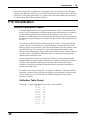
PTC10 Calibration
Custom Calibration Tables
Calibration Table Format
Calibration Table Units
Calibration Table Errors
16
16
16
17
18
Operation
19
Front-Panel User Interface
“Help” key
“Output Enable” key
“Select” screen
“Numeric” screen
“Plot” screen
“Program” screen
“Channel” screen
Alarm menu
Cal menu
PID menu
Tune menu
“System” screen
19
19
19
20
21
21
26
31
34
35
36
38
39
PTC10 Programmable Temperature Controller
Contents
Macros menu
Log menu
COM menu
IP menu
Display menu
Other menu
ii
39
40
40
41
41
43
Remote Programming
45
Introduction
45
Connecting to the RS-232 Interface
46
Connecting to the USB Device Interface
46
Connecting to the GPIB Interface
47
Connecting to the Ethernet Interface
47
Communication, Assembly, and Run-Time Errors
48
Concurrent Macros
48
Command Syntax
49
Instruction List
General Instructions
IEEE 488.2 Instructions
Program Submenu
System Submenu
System.Log submenu
System.COM submenu
System.IP submenu
System.Display submenu
System.Other submenu
<channel> Submenu
<channel>.alarm submenu
<channel>.cal submenu
<channel>.PID submenu
<channel>.Tune submenu
Error Codes
52
52
54
58
60
60
61
61
62
63
64
68
69
70
73
73
Startup Macro
74
Sample Macros
74
PC Applications
77
PTCFileConverter
77
FileGrapher
File menu
Edit menu
Process menu
Special menu
Command line and macro instructions
79
79
79
80
82
82
PTC10 Programmable Temperature Controller
Contents
Circuit Description
iii
85
Core Sysytem Cards
PTC210 CPU Board
PTC220 Backplane
PTC230 Front panel
PTC240 GPIB Card
I/O Cards
PTC321 RTD Reader
PTC330 Thermocouple Reader
PTC420 AC Output Card
PTC430 DC Output Card
PTC510 Analog I/O Card
PTC520 Digital I/O Card
Parts List
85
85
85
88
89
89
90
91
92
92
93
94
95
PTC210 CPU Board Parts List
95
PTC220 Backplane Parts List
99
PTC230 Front Panel Parts List
101
PTC240 GPIB Option Parts List
PTC321 RTD Reader Parts List
103
104
PTC330 Thermocouple Reader Parts List
107
PTC420 AC Output Card Parts List
111
PTC430 DC Output Card Parts List
PTC510 Analog I/O Card Parts List
113
115
PTC520 Digital I/O Parts List
117
Schematics
121
PTC10 Schematic Diagram List
121
PTC10 Programmable Temperature Controller
Safety and Preparation for Use
v
Safety and Preparation for Use
Line Voltage
The PTC10 operates from a 88 to 264 VAC power source having a line frequency
between 47 and 63 Hz.
Power Entry Module
A power entry module, labeled AC POWER on the back panel of the PTC10, provides
connection to the power source and to a protective ground.
Power Cord
The PTC10 package includes a detachable, three-wire power cord for connection to the
power source and protective ground.
The exposed metal parts of the box are connected to the power ground to protect against
electrical shock. Always use an outlet which has a properly connected protective ground.
Consult with an electrician if necessary.
Grounding
A chassis grounding lug is available on the back panel of the PTC10. Connect a heavy
duty ground wire, #12AWG or larger, from the chassis ground lug directly to a facility
earth ground to provide additional protection against electrical shock.
Line Fuse
Use a 10 A/250 V 3AB Slo-Blo fuse.
Operate Only with Covers in Place
To avoid personal injury, do not remove the product covers or panels. Do not operate the
product without all covers and panels in place.
Serviceable Parts
The PTC10 does not include any user serviceable parts inside. Refer service to a qualified
technician.
PTC10 Programmable Temperature Controller
Safety and Preparation for Use
vi
Symbols you may Find on SRS Products
Symbol
Description
Alternating current
Caution - risk of electric shock
Frame or chassis terminal
Caution - refer to accompanying documents
Earth (ground) terminal
Battery
Fuse
On (supply)
Off (supply)
PTC10 Programmable Temperature Controller
Specifications
vii
Specifications
PTC10 Temperature Controller
Data acquisition rate
Temperature resolution
PID feedback
Data display
Alarms
Analog ports
# of ports
Range
Resolution
Update rate
Connector
Computer interface
Power
Dimensions
Weight
Warranty
1 to 50 Hz
<0.001 °C
Both manual and auto-tuning
modes are available.
320 × 240 pixel touchscreen.
Both numeric and graphical
data displays.
Upper and lower temperature
limits, and rate-of-change limits
can be set on each channel. If
exceeded, an audio alarm and a
relay closure will occur.
4 configurable DAC or ADC ports
±10 VDC
24-bit input, 16-bit output
50 Hz
BNC
USB, Ethernet, and RS-232.
GPIB (IEEE488.2) is optional.
10 A
88 to 132 VAC or 176 to 264 VAC,
47 to 63 Hz or DC
17"× 5" × 18" (WHL)
25 lbs.
One years parts and labor on defects in material and
workmanship.
PTC321 Pt RTD Card
Temperature range
Inputs
Excitation
Accuracy
Noise
Temp. coefficient
Signal conditioning
Signal detection
−200 °C to 550 °C
Four 100 W Pt RTD 4-wire inputs
1 mA
±30 mK
2 mKrms (10 samples/s)
1.4 mK/°C
Selectable 1 and 10 second time
constant digital LPFs are provided.
Card detects open and short circuit
conditions.
PTC330 Thermocouple Card
Thermocouple types
E, J, K, or T
PTC10 Programmable Temperature Controller
Specifications
Temperature range
E-type
J-type
K-type
T-type
Inputs
Input capacitance
Connector type
Accuracy
Noise
Temp. coefficient
CMRR
Common mode isolation
viii
−270 °C to 1000 °C
210 °C to 1200 °C
−270 °C to 1370 °C
−270 °C to 400 °C
Four thermocouple inputs
<1 pF
Omega mini thermocouple jacks
±500 mK (over 12 months)
20 mKrms (10 samples/s)
20 mK/°C
(type K thermocouple at 164.0 K)
100 dB
250 VAC
PTC420 AC Output Card
Output voltage
Max. output current
Cycle time
Max. line voltage
Surge current
Output resolution
Heater resistance (min.)
120/240 VAC
5A
Adjustable between 1 and 240 s
250 VAC
100 A max. (non-repetitive)
0.1 % at 10 s cycle time
24 Ω (110 VAC), 46 Ω (230 VAC)
PTC430 DC Output Card
Max. output voltage
Voltage ranges
Max. output current
Current ranges
Output resolution
Accuracy
Noise (rms), 25 Ω load
50 VDC
20 V and 50 V
1A
0.1 A, 0.5 A, 1 A (50 V) or 2 A (20 V)
16-bit (24-bit with dithering)
±1 mA (1 A range)
±0.1 mA (0.5 A range)
±0.01 mA (0.1 A range)
200 µV (2 A range)
15 µV (0.5 A range)
5 µV (0.1 A range)
PTC10 Programmable Temperature Controller
Quick Start Instructions
ix
Quick Start Instructions
This tutorial explains how to get the PTC10’s PID feedback loop running.
Plug a heater and a temperature sensor (thermocouple or RTD) into the PTC10’s back panel. The
temperature sensor should be closely connected to the heater.
Turn the instrument on. The Select screen appears. Touch the heater output and the temperature sensor
input channels, making sure that they and no other channels are highlighted.
Press the “Channel” key. At the top of the screen are two tabs, one for each of the two channels you
selected. Touch the tab for the temperature sensor.
Touch the “Lopass” button. This brings up a menu of available lowpass filter time constants. To get more
information about the Lopass setting, press the “Help” key. The “Help” key displays a pop-up window
PTC10 Programmable Temperature Controller
Quick Start Instructions
x
with a brief description of whichever menu is currently showing on the screen. Touch the “OK” button or
press the Help key again to dismiss the help window.
In the Lopass menu, touch the “10 s” option. This step applies a lowpass filter to the temperature sensor,
which greatly improves both the accuracy of the PID tuning process and the performance of the tuned
PID feedback loop. If your heater takes much longer than 10 seconds to heat up, select a larger lowpass
filter.
Still on the “Channel” screen, touch the tab for the heater output channel. In first “PID” column, touch the
“Input” button. This brings up a window showing the available input channels. Touch the temperature
input channel. This tells the PID feedback loop which temperature to control.
Next, touch the “Setpoint” button and enter the temperature you’d like the heater to heat the temperature
sensor to. Touch “OK” once you’ve entered the setpoint.
PTC10 Programmable Temperature Controller
Quick Start Instructions
xi
Touch “D” and set the derivative gain to 1. Any nonzero value tells the tuner that we want it to use
derivative gain. This makes the feedback more responsive. If D is set to 0, the tuner will leave it at 0. This
is sometimes necessary to avoid excessive noise in the feedback output.
In the “Tune” column, look at the “Step Y” and “Lag” controls. If the output is increased to the value
shown in “Step Y”, would you expect to see a noticeable rise in temperature within the time shown in
“Lag”? Would the amount of power shown in “Step Y” damage your system? Change these values if
necessary.
Turn the outputs on by pressing the “Output Enable” key twice. The Output Enable light turns on and a
tone sounds.
In the PID menu, touch “Mode” and select “auto”. This starts the autotuner.
Press the “Plot” button to see a graph of heater output and temperature. Press the “Plot” button several
times, until the two traces appear on two separate graphs. The heater output should increase to the value
that was set with the “Step Y” control, and the temperature should begin to increase.
Press the “Channel” key, and under “Tune”, touch the “Status” button. This brings up a tuning status
window that will tell you how close the autotuner is to finishing.
When tuning is finished, the PID feedback is enabled. Assuming that the input temperature is below the
setpoint, starts increasing power to the heater. The temperature may overshoot the setpoint, but it should
eventually settle down to the setpoint.
PTC10 Programmable Temperature Controller
Quick Start Instructions
xii
PTC10 Programmable Temperature Controller
Introduction
1
Introduction
The PTC10 is a high-performance laboratory temperature controller with autotuning, datalogging, and
graphical display. When connected to a temperature sensor and a heater, it tries to keep the temperature at
a user-specified value by varying the amount of power supplied to the heater. With up to 16 temperature
inputs and the ability to log to high-capacity flash memory sticks, the PTC10 can also be used as a
temperature logger. I/O cards are available to support various types of temperature sensors and heaters.
Hardware
The PTC10 has four wide and two narrow slots for I/O cards. Cards can be added, removed, or
rearranged without any changes to the PTC10’s firmware. For most purposes, the six slots are
identical and cards do not have to be arranged in any particular order. However, the lowernumbered slots are preferred for DC output cards because they get the most cooling from the fan.
In addition, alarms can only be used to activate relays on a digital I/O card when the card is
installed in slot 6.
Some settings (particularly PID feedback parameters, alarm settings, custom calibrations, and
lowpass filter settings) may be lost when I/O cards are rearranged.
Always unplug the PTC10 from the wall before opening the case. Any time the instrument is
plugged in, live line voltage could be present inside the system even if the instrument is
apparently not receiving power. Furthermore, removing and installing I/O cards while the power
is turned on may permanantly damage the instrument.
PTC321 RTD Reader
A resistance temperature detector (RTD) is a conductor whose resistance varies predictably with
temperature. RTDs are often made of platinum. Since platinum is very non-reactive it produces
sensors with exceptional long-term stability. However, platinum RTDs are also expensive and
have a limited range.
Typically, the resistance is measured by passing an excitation current through the RTD and
measuring the voltage across the resistor. A four -wire RTD has two wires to carry the current
and two to measure the voltage. Negligible current flows through the voltage-measuring wires,
ensuring that the resistance of the wires does not affect the measured voltage.
RTDs usually have either the “European” temperature coefficient of 0.00385 Ω/Ω/°C (IEC751
standard) or the much less common “American” coefficient of 0.00392 Ω/Ω/°C.
The PTC321 RTD reader reads up to four 100 ohm platinum RTDs with a 1 mA excitation
current. For maximum accuracy, the PTC321 uses 4-wire inputs. The current through the RTD
can be reversed with each reading to null out parasitic thermocouple voltages as well as 60 Hz
interference.
PTC10 Programmable Temperature Controller
Introduction
2
The standard PTC321 can read European-calibration RTDs in the temperature range −200 to
550°C and American-calibration RTDs in the range −200 to 540°C.
The PTC321 is calibrated at 25 and 35°C. An on-board temperature sensor continuously
interpolates between these two calibrations to account for thermal drift of the electronic
components. Since the PTC10 enclosure is usually elevated 2 to 3 degrees above ambient
temperature, the accuracy of the PTC321 is compromised whenever the ambient temperature
rises above about 32°C.
To further improve measurement stability, the PTC321 can control the main enclosure fan to
keep the card at a constant temperature (see the manual entry for the “PCB” control in the
“Channel” menu).
Connecting the RTDs
RTDs are connected to the PTC321 using removable 5-pin, 3.5 mm Weidmuller terminal plugs
(Weidmuller part number 169045). The plugs use a tension clamp to hold the RTD wires. To
install the RTD wires:
1. Hold the plug in front of you with the five small holes on top and the five larger holes on
the bottom.
2. In each hole is a metal clip. Place a small screwdriver into one of the small holes and
firmly push it in to the small gap above the clip. The screwdriver should go in about half
an inch. The thickness of the screwdriver shaft pushes the clip down toward the larger
hole.
3. The larger hole should open up. Place a stripped wire into the hole and remove the
screwdriver.
Plugs with screw clamps (Weidmuller 161409) can also be used. It’s easier to connect the RTD
wires to these plugs, but the wires often come loose, resulting in noisy temperature
measurements. The tension clamps are a little more difficult to install but produce a more reliable
connection.
On each connector, the top two pins receive the resistance signal, the middle pin is a ground that
can be connected to a shield or left unconnected, and the lower two pins provide the excitation
current.
Commercial 4-wire RTDs normally have two wires of the same color that are connected to one
end of the resisive sensor and two wires of a different color that are connected to the other end.
There is normally no shield. In this case, the RTD plug should be wired up in one of the
following two ways (assuming black and white wires):
Option 1
Option 2
Pin 1
White
Black
Pin 2
Black
White
Pin 3
Unconnected
Unconnected
Pin 4
White
Black
Pin 5
Black
White
If the plug is wired up any other way, no reading appears when the sensor is plugged into the
RTD reader.
PTC10 Programmable Temperature Controller
Introduction
3
PTC330 Thermocouple Reader
Any piece of metal develops a voltage between its two ends if the ends are at different
temperatures. The exact voltage depends on the temperature differential and the composition of
the metal. A thermocouple is made up of two metal wires that develop different voltages in
response to a given temperature differential. The two wires are connected together at one end,
and the difference in their voltages is measured at the other. The result is a sensor that measures
the difference in temperature between the “hot” junction (the point where the two thermocouple
wires are joined together) and the “cold” junction (the point where the thermocouple attaches to
the thermocouple reader). If the temperature of the cold junction is known, the temperature of the
hot junction can be calculated. Normally the cold junction temperature is measured with another
temperature sensor.
Thermocouples are inexpensive and can sense a wide range of temperatures, but they are accurate
to no more than 1°C, partly because they tend to oxidize or otherwise react with gases in their
environment.
Type E thermocouples have one chromel wire (“chromel” is a trade name for an alloy of 90%
nickel and 10% chromium) and one contstantan (60% copper, 40% nickel) wire. It has a large
voltage change per degree (68 µV/°C), resulting in excellent signal-to-noise ratio. However, its
long-term stability is not very good. Type E thermocouples are resistant to oxidation, but corrode
if used in a vacuum or other reduced-oxygen environment.
Type J thermocouples have one iron and one constantan wire. Above 500°C, oxidation of the
iron results in poor stability. This thermocouple is mainly used in legacy applications.
Type K thermocouples have one chromel and one alumel (95% nickel, 2% manganese, 2%
aluminum, 1% silicon) wire. With a wide temperature range and good stability, it is the most
popular type of thermocouple. Type K thermocouples are resistant to oxidation, but corrode if
used in a vacuum or other reduced-oxygen environment.
Type T thermocouples have one copper and one constantan wire. They are very accurate and can
be used in reducing atmospheres, but their temperature range is limited.
The following table summarizes some properties of thermocouples. The temperature range is the
range that the thermocouple itself can withstand without losing its calibration. The “standard
calibration” accuracy is the IEC 584-2 standard for thermocouple-to-thermocouple material
variation. Not all commercial thermocouples may follow this standard; for example, Omega
specifies an accuracy of 2.2°C for its type J and K thermocouples. This is the accuracy that a
standard calibration curve for type E, J, K, or T thermocouples are used. Greater accuracy is
possible if your thermocouple is custom calibrated. The values in this table only reflect the
accuracy of the thermocouple itself, and do not account for the accuracy of the PTC330.
Temperature range
E
J
K
T
Temperature
range
Sensitivity,
µV/°C at 25°C
−200 to 870
0 to 760
−200 to1260
−200 to 350
60.9
51.7
40.6
40.6
Accuracy
Standard
Custom
calibration, calibration,
°C, at 0°C °C, <300°C
1
1.7
1.5
0.1
0.1
1.5
0.1
0.5
PTC10 Programmable Temperature Controller
Introduction
4
The PTC330 thermocouple reader is factory-configured to read either type E, J, K, or T
thermocouples. The card has an internal cold junction block equipped with a Pt100 RTD
temperature sensor. To connect a thermocouple, the thermocouple must be equipped with a
miniature jack such as Omega part number SMPW-K-M for type K, SMPW-J-M for type J, etc.
The cold junction temperature is normally added to the thermocouple readings. It is also recorded
separately so that, if unexpected drift or other artifacts appear in the thermocouple readings, it
can be determined whether the artifacts are due to erratic behavior of the cold junction. If native
units are selected (System screen -> Other -> Units = “”), the thermocouple EMFs are displayed
in millivolts; the cold junction temperature is displayed in ohms and is not added to the
thermocouple data.
Because the PTC330 has optically-isolated inputs, the thermocouples can be directly contacted to
electrically live metal.
The measurement range that the PTC supports for each type of thermocouple (before the cold
junction temperature is added) is as follows:
E
J
K
T
−270 to 1000 °C
−210 to 1200 °C
−270 to 1372 °C
−270 to 400 °C
Outside this range, no reading will appear on the display and any feedback loops for which the
thermocouple is an input will not function.
To improve measurement stability, the PTC330 can control the main enclosure fan to keep the
card at a constant temperature (see the manual entry for the “PCB” control in the “Channel”
menu).
PTC420 AC Output Card
The PTC420 AC output card has a solid-state relay that can deliver up to 600 W of power (1200 W
when used with 240V line voltage) and is intended for control of large heaters including heating
mantles, heating tape, and heating blankets. The relay is either on or off; when on, the full 120 or
240 V of AC line voltage appears on the output. To vary the output power, the PTC430
repeatedly switches the relay on and off.
The card should be used with heaters having a resistance of 24 Ω or more if the line voltage is
120V, or 48 Ω or more if the line voltage is 240 Ω. If the heater has a smaller resistance, the card
will deliver more than its rated current and may be shut down by its internal protection circuitry.
In some cases the card may be damaged.
The maximum power that the PTC420 can deliver decreases with increasing heater resistance.
The total AC current delivered at any one time by the all the PTC420 cards in a single PTC10
cannot exceed 10 A. If it does, the PTC10’s main fuse will blow.
PTC10 Programmable Temperature Controller
Introduction
5
PTC430 DC Output Card
The PTC430 DC output card can deliver up to 50 W of power and is intended for precise control
of small heaters. The card offers two voltage ranges (50 V and 20 V) and three current ranges
(1A, 0.5A, and 0.1A). An auto-range feature continuously adjusts the current and voltage ranges
to the smallest values needed to achieve the power specified in the Hi Lmt setting.
The card can only achieve 50 W of output power when used with a 50 Ω heater. Heaters with
under 10 ohms of resistance may cause the card’s thermal protection circuitry to shut down the
output.
PTC510 Analog I/O Card
This card is included as standard equipment and fits in either of the two narrow I/O card slots.
Each of its four channels can be either an input (±10V, 24-bit ADC) or an output (±10V, 16-bit
DAC). Each channel has a red back-panel LED that lights up when the channel is an output.
The analog I/O channels can be used as PID inputs or outputs. Since each channel can only
supply up to 10 mA of current, the analog I/O can’t be used to drive a heater directly, but can be
connected to an external amplifier.
PTC520 Digital I/O Card
This card is included as standard equipment and fits in either of the two narrow I/O card slots. It
offers four relays, each capable of passing up to 5A of current. It also has eight isolated TTL I/O
lines on a 25-pin connector compatible with the pinout of the standard PC parallel port. The TTL
lines can be used as inputs or outputs, but all eight must have the same direction.
The relays are hosted on a single 12-pin pluggable terminal block. The four relays are labeled
“A” through “D”, and each relay has three connections labeled “NC” (normally open), “COM”
(common), and “NO” (normally open). When the PTC is turned off, or when outputs are not
enabled, or when the relay is set to 0, the “NC” pin is connected to the “COM” pin and the “NO”
pin is unconnected. When the relay is set to 1 and the outputs are enabled, the “NO” pin is
connected to the “COM” pin and the “NC” pin is unconnected.
The relays appear on the PTC10 display as a single 4-bit integer value between 0 and 15, with
relay A being the least significant bit.
PTC10 Programmable Temperature Controller
Introduction
6
The pinout of the digital I/O lines follows:
1
2
3
4
5
6
7
8
9
10
11
12
13
Unconnected
D0
D1
D2
D3
D4
D5
D6
D7
+5V
+5V
Gnd
Unconnected
14
15
16
17
18
19
20
21
22
23
24
25
Unconnected
Unconnected
Unconnected
Unconnected
Unconnected
Gnd
Gnd
Gnd
Gnd
Gnd
Gnd
Gnd
Since the digital I/O lines are floating, at least one “gnd” pin must be connected to the signal
ground of whatever system the digital I/O is interfaced with. Alternatively, if the digital I/O lines
are configured as inputs, a +5V pin can be shorted to any of the inputs D0 to D7 to pull them
high, or a “gnd” pin shorted to the inputs to pull them low. The +5V pins are current-limited with
4.7 kΩ resistors and are not intended to power a remote system.
The status of the eight digital I/O lines is reported on the PTC10 display as a single eight-bit
integer value. Each I/O line is assigned an integer value as shown in the following table:
Bit
D0
D1
D2
D3
D4
D5
D6
D7
D8
Value
1
2
4
8
16
32
64
128
256
The “DIO” value shown on the PTC10’s display is the sum of the values of all set bits. For
example, if bits D1 and D3 are set, a DIO value of 2 + 8 = 10 is displayed.
Using the remote interface, macros can be defined that associate the digital I/O lines with most
functions of the PTC10. The remote interface provides bitwise operators to set and query the
relays and digital I/O lines.
The DIO lines do not have to be used as independent I/Os and can instead be used to pass a
single, 8-bit value into or out of the PTC. The PTC treats the DIO like any other channel; for
example, its value can be plotted or used in a PID feedback loop.
PTC10 Programmable Temperature Controller
Introduction
7
Data Storage
The PTC10 logs data to removable USB memory devices. USB hard drives are recommended for
this purpose. Flash memory keys can also be used but often produce long delays during which the
PTC10 is nonresponsive, particularly when the memory key is first plugged in.
If the instrument is used without a USB memory device, the most recent 2048 data points from
each channel can be stored in internal RAM. This corresponds to the last 11 minutes of data at
the default logging rate of 3 points per second. Data older than 11 minutes disappears from the
graph. All other features of the PTC continue to work normally when no USB memory device is
plugged in.
The back panel of the PTC has two plugs for USB devices. The PTC logs data to the last USB
device to be plugged in. Thus, if one USB memory stick is plugged in, you can plug in a second
one and then unplug the first one without losing any data.
When a USB device is plugged in, it takes the PTC10 several seconds (normally about 5 seconds,
but sometimes up to 30) to recognize the device and begin logging to it. Look at the “Log to”
button (in the Log column of the “System” menu) to determine whether or not the PTC is logging
to a USB device.
The last USB memory device that was plugged in should not be unplugged without first turning
logging off. Also, the PTC should not be switched off while USB logging is enabled. In either of
these cases, recent data will be lost and the directory structure of the device can be corrupted.
ADC Sampling and Logged Data
The PTC10 has two different types of sampling rate, one which controls how often data is
acquired, and another that controls how often it’s stored.
The A/D Rate (analog-to-digital conversion rate) controls how often a data point is acquired
from each channel. All channels are read at the same A/D rate, which by default is 100 ms or 10
samples per second. The faster the A/D rate is, the more quickly the PID loops can respond to
changing temperatures.
By default, the A/D conversion process is synchronized with the AC line voltage. If the A/D rate
is set to 100 ms, A/D conversions occur every six cycles of the AC voltage if the PTC10 is
plugged into a 60 Hz AC wall socket, or every five cycles for 50 Hz AC. When the AC line
trigger is in use, the A/D rate can only be set to multiples of the AC line period. This prevents 60
Hz noise from aliasing into temperature readings, which would cause a slow sinusoidal variation
in the readings. 60 Hz noise still creates a constant offset in temperature readings, but the offset is
usually too small to be of concern with thermocouple readings and can be removed from RTD
readings using current reversal.
The Log Rate controls how often a data point is saved to each channel’s log. The log rate can be
set independently for each channel; the default is 300 ms or about 3 points per second. Normally
the time between log points should be longer than the time between A/D samples. In this case,
multiple A/D readings are averaged together to create each logged value. If the time between log
points is shorter than the time between A/D samples, each A/D reading is recorded more than
once in the log.
PTC10 Programmable Temperature Controller
Introduction
8
Since the graph shows logged data, a slow log rate reduces the noise visible in the graphs and
may produce a stairstep appearance, while a fast log rate produces graphs with more detail.
Log File Structure
The PTC10 uses a proprietary binary data format. A utility program provided by SRS can be used
to convert the files to text format readable by other programs.
Each log file stores data for one channel and consists of a file header followed by one or more
records. Each record contains a record header followed by zero or more floating-point data
values. The floating-point values within a record are evenly spaced in time and are expressed in
the same units as on the PTC’s front-panel display. Not-a-number values (0x7fc00000 if read as
an integer) are recorded if the sensor or heater is unplugged for less than 100 log points. If the
sensor or heater is unplugged for more than 100 data points, no values are recorded and a new
record is created when the sensor or heater is plugged in.
A new record is created:
•
•
•
•
•
When the instrument is rebooted
When logging is turned off and back on again
When the logging interval is changed
When the system time is set
When a sensor or heater is plugged in after being unplugged for more than 100 log points
(in which case, no data points are logged while the sensor is unplugged)
By default, log files are given the name of the channel followed by the extension ".ptc", i.e.
"ChannelName.ptc". Each file can have a maximum of 256 records. Once this number of records
is reached, the file is closed and a new log file with a numeric extension ("ChannelName.000",
"ChannelName.001", etc.) is created. The highest allowed numeric extension is 256.
A description of the file format follows. All values are little endian.
File header:
Bytes 0–3: Format identifier. 4 ASCII bytes: ‘PTC0’ (or a 32-bit integer: 0x50544330).
Bytes 4–7: File format version number. The current version number is 1. Any other number
indicates that the format differs from this description. 4-byte unsigned integer.
Bytes 8–11: Location of first interval header, in bytes from the beginning of the file. 4-byte
unsigned integer. Must be at least 12.
An ASCII header may follow byte 11.
Record:
Bytes 0–3: number of data points in this record; if -1, this is the last record, and the number
of data points is equal to the number of bytes following this record header divided by four. 4byte signed integer.
PTC10 Programmable Temperature Controller
Introduction
9
Bytes 4–11: the time that the first data point in the record was acquired, expressed in
milliseconds since January 1, 1970. 8-byte unsigned integer.
Bytes 12–19: number of milliseconds between data points. 8-byte unsigned integer.
Bytes 20–23: checksum. The sum of all data points. 4-byte signed integer.
This is the end of the record header. The data values begin immediately after:
Bytes 24–27: data point 0. 4-byte IEEE floating-point value.
Bytes 28–31: data point 1. 4-byte IEEE floating-point value.
etc.
The size of a log file cannot exceed 4 GB, or about one billion data points per channel. At the
default 1 second log rate, this limit is reached in about 30 years.
System Fan
The PTC10’s fan prevents output cards from overheating and regulates the temperature of input
cards.
At every A/D conversion, each I/O card determines how much cooling it needs based on readings
of internal temperature sensors. The I/O card requests that amount of cooling from the system.
When the fan speed is set to “Auto”, the PTC10 continuously calculates the fan speed based on
the requirements of whichever card needs the most cooling at the moment.
For output cards, the amount of cooling needed depends on the temperature of certain internal
components and the amount of current being delivered.
The PTC321 RTD reader and the PTC330 thermocouple reader have an onboard temperature
sensor. Using an internal feedback loop, they attempt to maintain their internal temperature at a
certain value by requesting cooling from the system. The target temperature is specified with the
“PCB” setting in the “Channel” menu. In general, as long as the temperature of an input card is
below its PCB setting, it doesn’t request any cooling and its temperature is unregulated. Since the
normal temperature of these cards is a few degrees below the default PCB setting of 30°C, their
temperature is only regulated when the PTC10 gets unusually warm.
The input cards request are sensitive to variations in ambient temperature (the RTD reader
compensates for ambient temperature variations using its on-board temperature sensor, but its
performance is still improved if its temperature is stable). To improve the stability of the input
cards, the PCB setting of one card can be reduced to a value just below its normal temperature,
such that the fan is always running and the card’s temperature is continuously being regulated.
However, if the PTC10 has to output a large heater current, the fan speed will increase to keep
the output card cool and the temperature of the input cards may fall out of regulation.
PTC10 Programmable Temperature Controller
Introduction
10
PID Feedback
The PTC10 uses a Proportional, Integral, and Derivative (PID) feedback loop to control
temperature. This feedback loop combines three algorithms to calculate the optimal heater power
at any given moment.
The proportional feedback algorithm determines the error, (i.e. the difference between the desired
temperature (the setpoint) and the actual temperature), T. The output Yp of the proportional
feedback algorithm is just the error multiplied by a constant, P:
E(t) = (setpoint – T(t))
Yp(t) = P · E(t)
As the actual temperature approaches the setpoint, the proportional output P decreases to zero.
Therefore proportional feedback cannot, in general, keep the temperature at the setpoint.
The integral feedback algorithm multiplies the error by a constant (Ki) and adds the result to the
previous integral output:
Yi(t) = Ki · E(t) + I(t–1)
As the actual temperature approaches the setpoint, the rate of change of the integral output I
drops to zero. In effect, integral feedback sets the steady-state heater power.
Derivative feedback attempts to predict what the actual temperature will be in the future by
multiplying the rate of change of the actual temperature by another constant:
Yd(t) = D * (T(t–1) – T(t))
When the temperature is increasing, derivative feedback reduces power to the heater; when the
temperature is decreasing, derivative feedback increases power to the heater.
The heater power is the sum of the three feedback algorithms:
Heater power = Yp(t) + Yi(t) + Yd(t)
In general, as the proportional and integral gains are increased, the feedback loop responds more
quickly and the actual temperature more closely tracks the setpoint. If P and I are increased too
much, though, the heater power and temperature begin to oscillate.
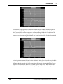
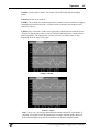
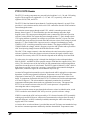
The figure below shows the effect of changing the proportional gain. The top graph shows the
power being delivered to two identical heaters by separate PID feedback loops, while the bottom
graph shows the temperature of each heater. Each feedback loop uses the proportional, integral,
and derivative algorithms, but the feedback loop plotted in grey has a higher proportional gain.
At 30 seconds, the setpoint is increased from 30 to 35°C. The white feedback loop, with a low
proportional gain, immediately increases the heater power to 10 W. The grey feedback loop, with
a proportional gain twice as high, immediately increases heater power to 20 W. As a result the
temperature increases more quickly, but then overshoots the set point.
PTC10 Programmable Temperature Controller
Introduction
11
Increasing the integral gain has a similar effect, but the integral feedback does not respond as
quickly. The ability of integral feedback to remember its past state effectively adds a delay,
which in turn is likely to cause temperature oscillations. Integral feedback is needed to set the
overall level of the heater output, while proportional feedback is needed to provide an immediate
response to perturbations. As a rule of thumb, the integral gain should be an order of magnitude
smaller than the proportional gain.
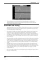
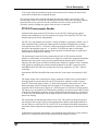
Derivative gain prevents oscillations, but also adds noise. In the figure below, the grey feedback
loop has more derivative gain, which prevents the temperature from overshooting the setpoint.
This means that the loop can use higher proportional and integral gains, producing faster, more
responsive feedback control. However, the output signal is much noisier. When the derivative
gain is nonzero, the feedback input should always be low pass-filtered to reduce output noise.
PTC10 Programmable Temperature Controller
Introduction
12
The key challenge to using a PID feedback loop is identifying the best feedback gains.
Autotuning algorithms can help by measuring how quickly and how much the temperature
changes when the output power is changed.
Automatic PID Tuning
When the PID mode is set to “Auto”, the PTC10 starts either a step response or a relay autotuner.
Both tuners require that the temperature be stable before they begin. Either tuner can be started
even if the PID feedback is already running.
If the derivative feedback gain is initially zero, the autotuner calculates P and I feedback gains
and leaves D set to zero. If the derivative feedback gain is initially nonzero, the autotuner
calculates P, I, and D feedback gains. Setting D to a nonzero value before autotuning produces
more aggressive, faster-acting feedback. However, derivative feedback is sensitive to noise and
requires a lowpass filter. If your temperature sensor is noisy or you’re not using a lowpass filter,
leave D set to zero.
If the tuner finishes successfully, a high-pitched tone plays and the feedback mode automatically
changes to manual, turning the feedback loop on. If the tuner was unsuccessful (Output Enable
was off, the heater was unplugged, the temperature sensor was unplugged, or the heater was out
of range), a low-pitched tone plays and the feedback mode changes to off, disabling feedback
control.
When PID tuning is started, a tuning status window appears that shows information about the
autotuner’s progress. This window can be dismissed by touching the “OK” button or any menu
key. Dismissing the window does not cancel the PID tuning process; to cancel PID tuning, either
set the tuning Mode control to “Off”, touch the output channel’s “Off” button, or press the
“Output Enable” key.
If the status window is dismissed, it can be made shown again by touching the “Status” button in
the output’s “Channel” menu.
PTC10 Programmable Temperature Controller
Introduction
13
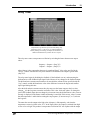
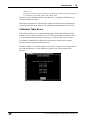
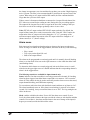
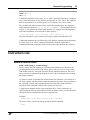
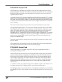
Relay Tuner
Temperature (top) and heater power (bottom) during relay
autotuning. Step Y is 1 W, Lag is 10 s, and the feedback is
initially running. Once tuning is complete, the feedback is reenabled and stabilizes the system at the 50°C setpoint.
The relay tuner creates a temperature oscillation by switching the heater between two output
values.
Outputhigh = OutputI + (Step Y)/2
Outputlow = OutputI – (Step Y)/2
where OutputI is the output when the tuner is started and Step Y is the value specified in the
“Step Y” control. Note that the relay tuner cannot be started unless the output is greater than
(Step Y)/2.
The relay tuner begins by disabling the feedback (if the feedback was on), and measuring the
drift and noise of the feedback input signal in the absence of any changes to the feedback output.
The drift-and-noise measurement continues for one-third the amount of time specified with the
“Lag” control, and the drift-and-noise value is the difference between the largest and smallest
input signal during this time.
After the drift and noise measurement, the relay tuner sets the heater output to the low value
(Outputlow) for the Lag time to start the oscillation. This is the “kick start” phase. If, during this
period, the feedback input does not change by at least ten times the drift-and-noise value, an error
message is displayed in the Status window and tuning is cancelled. If this occurs, either 1) ensure
that the temperature is stable before starting the step response; 2) increase step Y; or 3) increase
the Lag time.
The tuner then sets the output to the high value (Outputhigh). Subsequently, each time the
temperature crosses its initial value, 50 °C in the figure above, the output is switched from high
to low or low to high. This produces a temperature oscillation 180° out of phase with the output
PTC10 Programmable Temperature Controller
Introduction
14
oscillation. The tuner performs two oscillation cycles, not including the kick start, and measures
the period and amplitude of the second oscillation.
The relay tuner has to wait four times for the temperature to cross its initial value. If the
temperature measurement is disturbed during this time (for example, if the temperature sensor is
moved, or if the sensor is in an oven and the oven door is opened), the temperature may never
cross its initial value and the tuner may run indefinitely without finishing.
The feedback parameters calculated by the relay tuner are intended to produce about 25%
overshoot.
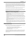
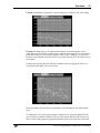
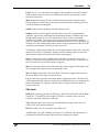
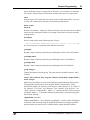
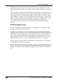
Step Response Tuner
Temperature (top) and heater power (bottom) during step resonse
autotuning. Step Y is 0.9 W, Lag is 10 s, feedback is initially off,
and the system starts at room temperature. After the step response
is complete, the feedback turns on and stabilizes the system at the
60°C setpoint.
The step response tuner changes the feedback output and estimates PID parameters by measuring
the slope and magnitude of the feedback input’s response.
The step response tuner begins by disabling the feedback (if the feedback was on), and measuring
the drift and noise of the feedback input signal in the absence of any changes to the feedback
output. The drift-and-noise measurement takes one-third the period specified with the “Lag”
control, and the drift-and-noise value is the difference between the largest and smallest input
signal during this time.
Next, the step response tuner increases the output by the value specified with the “Step Y”
control. The tuner then waits for the amount of time specified with the “Lag” control. If during
this period the feedback input does not change by at least ten times the drift-and-noise value, an
error message is displayed in the “Status” window and tuning is cancelled. If this occurs, either
1) ensure that the temperature is stable before starting the step response; or 2) increase step Y; or
3) increase the Lag time.
PTC10 Programmable Temperature Controller
Introduction
15
The tuner continuously measures how quickly the feedback input changes, (i.e., the slope of a
feedback input vs. time plot). Tuning ends once the lag period has passed and the most recent
slope is less than half the maximum slope. The tuner then calculates the maximum slope, the lag
time, and the total response, and uses these values to calculate the PID gains. Because the slope
calculation is sensitive to noise, it’s important to enable the “lopass” filter on the feedback input
channel to achieve accurate tuning results.
The step response tuner uses a slope calculation, while the relay tuner does not. Since the relay
tuner does not require a slope measurement, it’s usually the more accurate of the two.
If the tuning mode is set to “Auto”, the PTC10 selects the step response tuner if the relay tuner
would cause the output to drop below its lower limit. For example, if the output is off (and can’t
go negative) when autotuning is started, the step response tuner runs.
Suggestions for Best Tuning Results
•
•
•
•
•
•
While tuning, use the “Plot” display to graph the heater output and the temperature on
separate graphs. Make sure that you can see the temperature begin to rise or fall after the
heater output changes.
If tuning fails, let the temperature stabilize and try increasing the step Y or lag before
attempting to tune again. You may also need to increase the lowpass filter time constant.
The temperature must be stable when tuning is started. Either the feedback must be running
and stabilized at the setpoint, or the heater must be off and the temperature stabilized at room
temperature.
Set the lowpass filter on the input (temperature) channel to a value just below the expected
response time of the system. The step response tuner in particular requires adequate lowpass
filtering to produce accurate results.
Make sure the system doesn’t experience any temperature disturbances during the tuning
process.
Since the ideal feedback parameters usually vary with temperature, run the tuning algorithm
at about the temperature at which the feedback will be used. You may need to tune at room
temperature, then let the feedback bring the system to its working temperature, and re-tune at
the working temperature.
Filter Interactions
The PTC offers several filters that modify the raw sensor readings. These filters can sometimes
interact with each other. In the order in which they are applied, the filters are:
1. Sensor calibration (converts raw sensor output to temperature)
2. Offset/gain calibration (multiplies a channel by a gain and adds an offset)
3. Difference (takes the difference between two channels)
4. Lowpass (filters out noise)
The filters must be applied in this order so that difference readings can be accurately calculated
(incorporating the offset/gain calibration) and properly lowpass-filtered (lowpass-filtering two
signals before taking the difference between them causes artifacts if the filters don’t have the
same time constant).
PTC10 Programmable Temperature Controller
Introduction
16
Because the lowpass filter is applied last, any changes to the sensor calibration, the offset/gain
settings, or the difference filter are low pass filtered and may take some time to achieve their full
effect. Also, if the gain is increased by, say, a factor of two, the sensor reading may not increase
by a factor of two if the difference filter is enabled.
PTC10 Calibration
Custom Calibration Tables
A custom calibration table can be applied to any channel. To use a custom calibration,
create a text file containing the calibration information as described below. The name of
the file should be the name of the channel plus the extension “.txt”. Create a /cal/
directory on a USB storage device and put one file into the directory for each channel to
be calibrated. Plug the storage device into the PTC, and the PTC will automatically load
the files.
To verify that a particular file has loaded, bring up the “Select” screen by pressing the
“Select” menu key. If a channel uses a custom calibration, the upper-left corner of its
button is clipped. For more details, select the relevant channel, press the “channel” menu
key, and look in the “Cal” column. The “Type” button should read “custom”, and a
“Details” button should appear at the bottom of the column. Press the “Details” button to
view the first three and last three calibration points, or a message describing why the
calibration data could not be read.
Once the calibration files have been loaded, the USB device can be removed and the
custom calibrations remain in effect. The only way to change a calibration is to plug in a
USB drive with a different calibration file. The only way to return to the default
calibration is to turn the instrument off and then restart it without the calibration file
present on the USB device.
It can take several seconds for the PTC to recognize a USB device. Therefore, when an
instrument is turned on with a USB device plugged in, the instrument may acquire data
or drive outputs for a few seconds with the default calibration before the custom
calibration is loaded.
Calibration Table Format
Following is a sample calibration file for a 100 Ω platinum RTD:
100.00,
0,
103.90, 10,
107.79, 20,
111.67, 30,
115.54, 40,
119.40, 50,
123.24, 60,
127.08, 70,
130.90, 80,
134.71, 90,
138.51, 100
PTC10 Programmable Temperature Controller
Introduction
17
The calibration file must be an ASCII text file containing comma-separated sensor
readings and corresponding temperatures in the format “X, Y, X, Y” where X is a raw
I/O channel reading and Y is the value (normally a temperature) that X should be
converted to for display. The X values must be expressed in the native units of the
channel: for example, ohms for resistive sensors, millivolts for thermocouples, or volts if
the channel is a general-purpose analog input. The Y values are normally expressed in
°C, but different units can be specified by adding a “units” declaration as described
below. The calibration data must cover the entire expected range of sensor
measurements, which in this case is 0 to 100°C. If sensor readings fall outside the range
of the calibration data, the PTC behaves as if the sensor were disconnected: no data
appears on the graph or other data displays, and if a PID feedback loops uses the sensor
as an input, it freezes its output.
Newlines, spaces, or other non-numeric characters can appear between the values in
addition to the commas, but cannot replace the commas. For example, as shown above
each XY pair can be placed on its own line. The file cannot contain more than 4095
characters (about 200 XY pairs) and must have at least two XY pairs. Commas should
not be used within numeric values.
The data points don’t have to be consistently spaced, but consistent Y spacing produces
the most accurate results. For RTDs, the interval between data points should be 10°C or
less to ensure the best possible (0.1 mK) interpolation accuracy. Interpolation is less
accurate between the first and second X,Y points and between the last and next-to-last
points in the table. The sample table above, for example, is most accurate between 10°C
and 90°C.
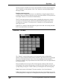
Calibration Table Units
The X values of the calibration table are always expressed in the native units of the
channel: ohms for resistive sensors, millivolts for thermocouples, volts for analog I/O
channels. For heater driver channels, the native units are by default watts, but can be
changed to percent, volts, or amps with the “Units” control in the Channel menu.
The Y values are normally expressed in °C. While it’s acquiring data, the PTC
automatically converts the Y-values from °C to the units specified in the System menu.
Optionally, the calibration file can begin with a units declaration in the form “units = °C”
(on Windows computers, hold down the alt key and type “0176” on the number pad to
get the degree sign). A units declaration overrides the System menu’s units setting and
can even be used to convert data to non-temperature units.
The units can be any string of 4 or fewer characters and must not contain any spaces.
Because anything following the units on the first line of the file is ignored, the XY data
should begin on the second line. If the units are declared, all temperature data in the
calibration file must be expressed in the declared units. While the PTC is running,
readings for this channel always appear in the declared units, regardless of whether the
PTC10 is configured to display temperatures in °C, °F, or K.
For example, the sample calibration table above could also be written as:
PTC10 Programmable Temperature Controller
Introduction
18
units = °C
100.00,0,103.90,10,107.79,20,111.67,30,115.54,40,119.40,50,123.24,6
0,127.08,70,130.90,80,134.71,90,138.51,100
In this case, sensor readings would always appear in °C, regardless of which units are
selected on the System menu.
If the units are declared for a thermocouple channel, the cold junction reading must be
expressed in the same units, otherwise the cold junction compensation will not work.
Calibration Table Errors
If the calibration file can’t be read, no readings appear for the affected channel. This
condition occurs if the file contains an X or Y value with no numeric characters, if X or
Y is not monotonically increasing or decreasing, or if the file ends with an X value.
If a channel is renamed, the calibration file also has to be renamed, or the custom
calibration will no longer be read on power-up.
Press the Channel->Cal->Details button to see the first 3 and last 3 (X, Y) data points in
the custom calibration, or, if the calibration couldn’t be read, a description of the
problem.
PTC10 Programmable Temperature Controller
Operation
19
Operation
Front-Panel User Interface
The front panel has six menu buttons to the left of the display. These buttons can be
pressed at any time to display one of the six main screens. The front panel also has a
“Help” button that displays help text for whatever is currently on-screen, and an “Output
Enable” button that turns all the PTC10’s outputs on and off.
“Help” key
The “Help” key displays a popup screen that provides more information about whichever
window is currently visible. For example, to get a description of the “Value” setting in
the “Channel” menu, first touch the “Channel” key to bring up the Channel screen, then
touch the “Value” button to bring up the Value input window, and then press the “Help”
key. The “Help” key does not work with pop-up windows that just display text and don’t
provide any opportunity for changing a value, like the “Output Enable” window that
appears when you press the “Output Enable” key.
“Output Enable” key
When the PTC is turned on, all outputs are disabled (however, inputs function normally).
This safety feature gives you a chance to adjust the PTC’s settings before it begins to
provide power to the heaters. To turn on the outputs, press the “Output Enable” key
twice. A red light next to the “Output Enable” key turns on to indicate that the outputs
are active, and any PID feedback loops that were previously running begin to provide
power to the heaters.
If the outputs are enabled, pressing the “Output Enable” key once disables all outputs,
setting them to zero. Inputs continue to function normally. In an emergency situation, the
Output Enable key is the quickest way to turn off the PTC’s outputs. Re-enabling the
outputs immediately returns all outputs to their previous values.
In certain cases it may be desirable to have the PTC power up with the outputs enabled
to ensure that feedback loops automatically resume after a power failure. This can be
accomplished with a startup macro (see the “Startup macros” section).
The Output Enable key is not intended to prevent electric shocks. When handling
exposed heater wires, always disconnect the wires from the PTC10 or unplug the PTC10
from the wall.
Press and hold the "Output Enable" key for 3 seconds to put the PTC10 into standby
mode. In standby mode, the outputs are turned off, data acquisition and macros are
paused, the front panel display and system fan are shut off, and the system does not
respond to remote commands. RTD excitation currents are still on, and an internal
PTC10 Programmable Temperature Controller
Operation
20
cooling fan may switch on occasionally. Press the "Output Enable" key again to leave
standby mode.
“Select” screen
This screen has six columns of buttons. Each column represents one I/O card, and each
button shows the name and the current value of an I/O channel. The value may not
appear if no sensor or heater is connected to the channel.
A small dot appears in the upper-right corner of a button whenever the corresponding
channel’s alarm is triggered. The upper-left corner of the button is clipped if the channel
uses a custom calibration.
Touch one or more buttons to select which channels you’d like to view on the Numeric,
Plot, and Channel screens. The top of the Select screen has four Group tabs that let you
save and recall up to four groups of selected channels. Touch one of the tabs or
repeatedly press the “Select” button to change the selection group.
PTC10 Programmable Temperature Controller
Operation
21
“Numeric” screen
This screen displays the current values of the selected channels as numbers. The more
channels that are selected, the smaller the displays are. If enough space is available, the
type of sensor or output may be displayed, and an annunciator may appear that indicates
whether the sensor or heater is disconnected (“N/A”), over range (“Hi”), under range
(“Lo”), if Output Enable is off (“Off”), or if an internal error has occurred (“Err”).
Repeatedly press the “Numeric” button to cycle through the four selection groups.
“Plot” screen
This screen shows logged data from the selected channels on a graph. Touch the tabs at
the top of the screen to change the selection group.
PTC10 Programmable Temperature Controller
Operation
22
Four different types of graph are available:
Single: up to eight selected channels are shown together on one graph with a single Y
axis. If more than eight channels are selected, only the first eight are shown.
Multi: each channel is shown in its own graph with an independent Y axis. If more than
eight channels are selected, only the first eight are shown.
PTC10 Programmable Temperature Controller
Operation
23
Custom: each channel is assigned to a plot according to its Channel->I/O->Plot setting.
Ponytail: like Single plot, up to eight selected channels are shown together on one
graph. Each trace is offset by its initial value so that the trace begins at zero. The offset is
recalculated whenever you touch the graph to zoom or pan, or whenever you switch to
another screen and back to the Plot screen. If you don’t touch the PTC, the offset is never
recalculated.
Using the ponytail plot does not affect how channel values are logged; the offsets are
only applied to the plots, not to the log files.
In any plot mode, press the Plot key repeatedly to cycle through the four different plot
types.
To change the X axis scale, touch anywhere inside the plot. Touch the right half of the
plot to zoom in; touch the left half to zoom out; drag to pan. Whenever the most recent
data is visible on the graph, the graph automatically scrolls to keep the most recent data
PTC10 Programmable Temperature Controller
Operation
24
visible. If the most recent data is not visible, the words “X lock” appear in the bottomleft corner of the screen to indicate that scrolling is disabled.To show current data and
resume scrolling, touch the words “X lock”, or touch and hold anywhere inside the graph
for 2 seconds without moving your finger.
Graphs that appear together on a screen always have the same X axis range. However,
each selection group has its own, independent X axis range.
Changing the X axis scale
Horizontal panning
To change the Y axis scale, touch the area to the left of the Y axis. Touch the top half of
the Y axis to zoom out; touch the bottom half to zoom in; drag to pan. Touch and hold
for two seconds to restore auto-scaling. Each graph has its own, independent Y axis
scale.
PTC10 Programmable Temperature Controller
Operation
25
Changing the Y axis scale of the bottom graph
Vertical panning of the bottom graph
The Plot screen always shows logged data. If, for example, the log interval is set to 10 s,
the graph will have a “stairstep” appearance with a step every 10 seconds.
Each of the four selection groups has its own graph type (single, multi, etc.), X range, and
Y range. Therefore, when you change the selection group, the graph’s range may also
change.
PTC10 Programmable Temperature Controller
Operation
26
“Program” screen
A program is a set of one or more instructions that can be used to generate temperature
ramps or customize the behavior of the instrument. Programs can be entered from the
RS-232 or GPIB interface or from the program screen. In either case, their progress can
be monitored from this screen.
The Program screen has an Input window, which shows text received over RS-232 or
GPIB; a Messages window, which shows responses and error messages from the PTC10;
and a Progress window, which shows the list of instructions that make up the current
program.
There are also six buttons:
Play: if a program is displayed but not running, pressing this button starts the program. If
a program is running in the currently-selected tab, this button is highlighted and pressing
it stops the program.
Pause: temporarily pauses the program running in the currently-selected tab.
Clear: erases the Input, Messages, and Progress windows. This button cannot be pressed
while a program is running in the current tab.
Load: touch this button and a list of programs stored in memory is displayed. Programs
can be stored in memory with the “Save” button, by sending a “define” instruction to a
remote interface, by attaching a USB device with text files contained in a “Macros”
folder. Select a program from the list and its component instructions are displayed in the
Progress window, replacing whatever was previously in the window.
The “Load” button can be used to edit a previously-saved program. To call a previouslysaved program as a subroutine from a program that you’re composing, don’t use the
“Load” button, since it would erase the rest of the program. Instead, touch the “Progress”
PTC10 Programmable Temperature Controller
Operation
27
window and select the saved program from the list of commands. The “Load” button
cannot be pressed while a program is running in the current tab.
Save: saves the current program, as shown in the Input window, to memory. You’ll be
asked to supply a name for the program. Up to 15 programs can be saved. If 15 programs
are already saved, the Save button will have no effect.
Saved programs can be run using the “Load” button or called as subroutines by touching
a line in the “Progress” window. Saved programs can also be called by sending their
name (like any other instruction) over one of the remote interfaces.
Delete: touch this button to display a list of programs stored in memory. Select a
program from the list and it will be deleted from memory. The Delete button does not
affect the status of currently-running macros.
If a program is not running, you can compose or modify a program by touching a line in
the Progress window. Touching a blank line brings up a list of possible commands.
Touching a line that already contains an instruction brings up a list of three options: you
can add a new instruction on the line above the one that was touched; delete the
instruction that was touched; or replace the instruction that was touched.
Sending programs over RS-232, USB, GPIB, or Telnet
Programs can be entered from a remote interface such as RS-232, USB, Telnet, or the
optional GPIB port. Each line of text sent to the PTC10 is run as a separate program (the
entire program must be on a single line). If two or more lines are sent to the PTC10 in
quick succession, the programs may run concurrently; that is, the PTC10 does not finish
running the first program before beginning the second. However, the first program sent
will always begin running before the second program. If it’s preferable to run programs
sequentially, begin each line with the *PHO instruction..
See the “remote interface” section of this manual for more details.
Preparing programs as files on USB memory devices
The PTC10 can also read programs that are stored as text files a USB memory device.
This is the best way to enter longer programs.
Create a “Programs” folder in the root directory of the memory device. Type the
program in a word processing or text eding program, and save it as a .txt file in the
“Programs” folder. Plug the memory device into the PTC10. On the Program menu,
touch the Load button and the name of the program should appear along with any
programs that have been saved in the PTC10’s internal memory. The program can be run
just as if it were saved in the PTC10’s memory; however, after the USB device is
unplugged, the program is no longer available.
While the PTC10 is running you can unplug the USB device, use a PC to edit a program
stored on the device, plug the USB device back into the PTC10, and run the new version
of the program. To ensure that the PTC10 runs the new version of the program, use the
Program screen’s Load button to re-load the program.
Programs that are prepared as files can contain up to 4096 characters, and may include
multiple lines and comments (“#” indicates that the remainder of the line is a comment).
PTC10 Programmable Temperature Controller
Operation
28
Except for the first newline after a comment, all whitespace is ignored; each line can be
empty or can contain one or more instructions.
Preparing programs from the front panel
To enter a program from the front panel, press the “program” button and then touch the
Progress window. A list of available top-level commands appears.
Any button with a name ending in a dot brings up a sub-menu when pressed. For
example, the commands to change the feedback setpoint or alarm limits for a channel are
accessed by first touching the “channel” button.
Touch the left square bracket (the button in the upper-left corner). Square brackets
surround blocks of code to be repeated. You’re returned to the “Program” screen, where
the first line in the “Progress” window is now a left square bracket.
Touch the Progress window again, anywhere beneath the first line. The list of possible
instructions appears. Select “program.” from the list. Touching this button brings up a
PTC10 Programmable Temperature Controller
Operation
29
list of instructions that affect the program. For example, “cls” clears the Messages
window; “name” assigns a name to the program; and “kill” ends a named program.
Select “print”. An alphanumeric input screen appears where you can enter an argument
for the “program.print” instruction. Type “hello”.
Touch the OK button. You are returned to the Program screen and the instruction
“program.print “hello”” appears in the second line of the Progress window.
PTC10 Programmable Temperature Controller
Operation
30
Now enter the instruction: “program.pause 1 s”. The pause instruction has two
arguments that must be entered separately. First you’ll be shown a numeric input screen
where you can type “1”. Touch “OK” and you’ll get a second menu where you can enter
the units (“s”). The completed instruction will pause the program for one second.
Next, enter the instruction “program.print world” followed by “program.pause 1 s”.
Finally, enter the instruction “] 3”. This makes the program repeat everything between
the square brackets three times.
Press the start button. While the program is running, the current instruction is highlighted
and the total number of repetitions as well as the number of repetitions remaining
appears next to the right square bracket. In addition, while the program is running a new
tab (labeled “New program”) appears at the top of the screen. By touching this tab, you
can enter and start a second program while the first program is still running.
When the program is done, the messages “hello” and “world” should appear three times
in the Messages window.
PTC10 Programmable Temperature Controller
Operation
31
Once the program is finished you can press the start button to run the program again, the
“Save” button to save the program, or the “Clear” button to erase the program and the
Messages window.
Running concurrent macros
A macro can run a long period of time or even indefinitely. Using the program tabs it’s
possible to start a new macro before the previous macro has finished. It’s also possible to
run multiple instances of a saved macro simultaneously.
The PTC can run at most ten concurrent macros (including the startup macro, macros
received over all of the I/O ports, and macros started from the Program screen). If an
eleventh macro is started, a “Too many macros” assembly error is generated and the
macro does not run.
If the PTC10 is turned off and turned back on again, macros that were running when the
PTC10 was turned off are not restarted.
“Channel” screen
The “Channel” screen includes controls for all settings that affect individual data
channels. Sensor calibration, PID feedback parameters, and alarms are all set up through
this screen. Note that the layout of the screen varies depending on which channel is
selected; for example, only output channels have PID controls, while only input channels
have alarm controls.
Only one channel can be set up at a time. One tab appears at the top of the screen for
each channel in the current selection group; select the tab for the channel you want to set
up. Repeatedly pressing the “Channel” button cycles through the four selection groups.
Name: Sets the name of the channel. The name must have 10 or fewer characters.
Value: If the channel is an input, this button shows the most recent reading but is greyed
out, indicating that the reading can’t be changed from the front panel. If the channel is an
PTC10 Programmable Temperature Controller
Operation
32
output, the reading is not greyed out and pressing this button allows you to enter a new
output value. However, if PID feedback is turned on or Output Enable is off, changing
the value will have no effect.
Off: Pressing this button immediately sets the PID feedback mode to Off, cancels any
PID tuning processes currently operating on the channel, and sets the channel’s output to
zero or the “Low lmt” value, whichever is higher. This button is only available for output
channels.
Low lmt: This control, which is only available for output channels, sets the minimum
limit on the output. However, if the minimum is greater than zero, the output is still set
to zero whenever outputs are disabled with the “Output Enable” key. Limits are always
expressed in the same units as the value. The limits should normally be changed when
the output units are changed, since the limits are not automatically converted to the new
units.
Hi lmt: This control, which is only available for output channels, sets a maximum limit
on the output. It’s typically used to prevent the PID feedback loop from delivering
excessive power to a heater. If the high limit is less than the low limit, the low limit takes
precedence.
Range: if the I/O card offers multiple input or output ranges, pressing this button
displays a menu of available ranges. If the card only offers a single range, this button is
greyed out.
IO type: Each output channel has an ADC that can measure the actual output. The “IO
type” button determines whether the output that you see on the screen is the value
measured by the ADC (“Meas out”) or the value requested by the user or the PID
feedback loop (“Set out”).
The PTC’s general-purpose analog and digital I/O channels are bidirectional, (i.e. they
can be used to monitor external signals, or to produce signals). In these cases, the IO
type button has three settings: “Set out” means that the channel outputs a voltage and the
value you see on-screen is the value you asked for. “Meas out” means that the channel
outputs a voltage and the value you see on-screen is the value measured by the ADC.
“Input” means that you can drive the channel with an external voltage, and the channel
will measure that voltage.
Plot: Indicates which plot the channel will appear in when the “Plot” screen is showing,
the plot type is Custom (see the “Plot Screen” section above), and the channel is selected
on the “Select” screen. Choose one of eight plots for the channel to appear in, where plot
1 is the uppermost plot. If no channels are assigned to a given plot, the plot won’t appear
on the “Plot” screen. For example, if all selected channels are assigned to plot 4, only
one plot appears on the Custom plot screen.
Logging: By default, data is logged every 300 milliseconds. This global log rate can be
changed on the “System” screen (System -> Log). The Logging button makes it possible
to override the global log rate for individual channels.
Cycle (AC output card only): The PTC420 has a solid-state relay that can either deliver
full power or no power to the heater. To more precisely control the power delivered to
PTC10 Programmable Temperature Controller
Operation
33
the heater, power is switched on for some fraction of a preset cycle time, then switched
off for the remainder of the cycle. For example, if the cycle time is 10 seconds, the relay
might switch on at time t = 0 s, off at t = 1 s, on at 10 s, off at 11 s, on at 20 s, and so on.
This would produce 10% of the maximum output.
The Cycle instruction sets the on/off cycle time. Shortening the cycle period will reduce
temperature swings associated with switching the current on and off, but will also reduce
the lifetime of the relay. The cycle time must be between 1 and 240 seconds inclusive.
Dither (DC output card only): The DC output card has a 16 bit DAC. For greater
resolution, the least significant bit can be dithered. Dithering is enabled by default.
Current (RTD reader only): Controls the direction of the RTD excitation current.
Reverse the current to detect offsets due to parasitic thermocouple EMFs or 60 Hz noise.
In AC mode, these offsets are automatically removed by reversing the current at each
ADC reading. Each reported temperature is based on the average of two ADC readings,
effectively cutting measurement bandwidth in half.
PCB (RTD and thermocouple readers only): Sets the maximum printed circuit board
(PCB) temperature for all channels on the selected card. This option only appears for I/O
cards that have internal temperature sensors. If the card’s temperature exceeds the
maximum and the fan speed is set to “Auto” (in the System menu), the system will
increase the fan speed to reduce the card’s temperature.
The default maximum temperature setting is 30°C. Thermal drift of the RTD or
thermocouple inputs can be reduced by setting the PCB temperature of one card to a
lower value. This value should be a few degrees above room temperature, (i.e., 25°C).
Reducing the maximum PCB temperature results in tighter regulation of the PTC10’s
internal temperature, particularly of the selected card, at the expense of more fan noise.
However, if a DC output card is being used the system might sometimes turn up the fan
speed to prevent thermal damage to the output card, causing larger internal temperature
variations.
Diff (input channels only): The value of the channel selected with the “Diff” button is
continuously subtracted from whichever channel is selected in the tab bar at the top of
the “Channel” menu. To turn the difference feature off, touch “Diff”, then touch
whatever channel is currently selected. The “Diff” button then shows an empty value.
Channels with a difference filter can be used as the input for PID feedback loops, in
which case the feedback maintains a constant temperature differential between two
locations, rather than a constant absolute temperature.
Lopass (input channels only): If a non-zero value is selected, a 6th-order RC lowpass
filter is applied to the selected channel. The lowpass filter removes noise with a period
shorter than the indicated time constant but also increases the effective response time of
a sensor.
The lowpass filter should always be enabled on the temperature inputs of all PID control
loops. This is especially true when using step response PID tuning or when derivative
feedback is enabled (i.e., the derivative gain is nonzero), since these algorithms calculate
PTC10 Programmable Temperature Controller
Operation
34
the change in temperature over time and therefore produce poor results if high-frequency
noise is present. The filter’s time constant should be just below the response time of the
system. When using an AC output card for PID control, the filter constant should be
longer than the cycle time of the output.
When a sensor is disconnected and then reconnected to a lowpass-filtered channel, the
PTC allows one second for the reading to settle. During this time, no reading appears.
The output of the lowpass filter is then set equal to the next ADC reading so that you
don’t have to wait for the reading to gradually settle to its new value.
Units (PTC420 AC output card and PTC430 DC output card only): By default, the
output of these heater driver cards is measured in watts. Using the “Units” button, the
output units of the AC output card can be changed to “%” (i.e., percentage of the
maximum output) and the output units of the DC output card can be changed to “A”
(heater current) or “V” (heater voltage).
Alarm menu
Each input can be assigned an alarm that triggers whenever the input exceeds preset
limits. As long as it remains in the triggered state, the alarm can do any of the following:
• Play a sound
• Trip a relay on the digital I/O card
• Shut off an output channel
The alarm can be programmed to remain triggered until it is manually shut off (latching
alarm), or to shut itself off as soon as the input returns to a value within the alarm limits
(non-latching alarm).
To determine which alarms are currently triggered, look at the Select screen. A small
white dot in the upper-right corner of a button indicates that the corresponding channel’s
alarm is in the triggered state.
The following controls are available for input channels only:
Status: indicates if an alarm condition is currently present on this channel. If a latching
alarm has been triggered, touch the Status control and set its status to “Off” to turn the
alarm off. This control can also be used to artificially turn the alarm on to test the sound,
output channel disabling, and GPIB status reporting.
To test an alarm, enable the alarm with the Mode control and then set its Status to “On”.
The alarm immediately turns on. If the alarm is non-latching, it turns off in less than a
second; if it is latching, it stays on until the Status is set to “Off”. The Lag setting has no
effect on this test.
Mode: enables or disables the alarm. If set to Off, the alarm never sounds. If set to
Level, the alarm sounds whenever the input exceeds the values set with the Min and Max
controls. If set to Rate /s, the alarm sounds whenever the rate of change of the input (in
degrees per second) exceeds the Min or Max values.
PTC10 Programmable Temperature Controller
Operation
35
Latch: if set to “Yes”, the alarm, once triggered, stays on until it is turned off with the
Status or Mode control. If set to No, the alarm turns itself off once the input is again
within the alarm limits.
Mute: temporarily silences the alarm sound but does not otherwise affect the alarm.
Once this button is touched, the alarm stays muted until the alarm condition goes away
or until the button is touched again.
Sound: controls which sound plays when the alarm goes off.
Output: the alarm, when triggered, can shut off one of the PTC’s output channels,
setting the output to zero and temporarily disabling that channel’s feedback loop. Once
the alarm status returns to “Off”, the output returns to its previous value and the
feedback is re-enabled. This feature can be used to guard against runaway feedback
loops or to otherwise protect equipment from damage due to excessive temperatures. For
example, one or more backup temperature sensors can be programmed to shut off a PID
output to prevent damage in case the primary sensor fails.
Touching the “output” button brings up a list of output channels; from this list, select the
channel to be shut off. If a channel is already selected, touching it again de-selects the
channel and no channel will be shut off when the alarm triggers.
Relay: if a digital I/O card is installed in slot 6, the alarm can switch one of its four
relays on. It’s possible to assign more than one alarm to a given relay, in which case the
relay will turn on if any one of the alarms is triggered.
Min: the lowest permissible value of the input. The alarm is triggered if the input (or the
rate of change of the input) becomes lower than this value.
Max the highest permissible value of the input. The alarm is triggered if the input (or
the rate of change of the input) exceeds this value.
Lag: prevents noise or glitches from inadvertantly triggering the alarm. The alarm will
not be triggered until the input has continuously exceeded the min or max setting for this
number of seconds. The lag applies when the alarm is being switched and when it is
being switched off.
Cal menu
RTD (RTD reader only): Selects the RTD type. Choose ITS-90 for RTDs with an alpha
of 0.00385 °; US for RTDs with an alpha of 0.00392; or custom to enter your own
Callendar–van Dusen calibration coefficients.
Type (Thermocouple reader only): indicates which thermocouple type the I/O card
expects. This value cannot be changed.
R0 (RTD reader only): The resistance of the RTD at 0°C.
A (RTD reader only): The Callendar–van Dusen “A” coefficient. The temperature t is
calculated from the RTD resistance Rt based on the following calculation:
PTC10 Programmable Temperature Controller
Operation
36
Rt = R0(1 + At + Bt² + (t −100)Ct³) below 0°C
Rt = R0 (1 + At + Bt²) above 0°C
where R0 is the resistance of the RTD at 0°C, and A, B, and C are the Callendar-van
Dusen coefficients.
B (RTD reader only): The Callendar–van Dusen “B” coefficient.
C (RTD reader only): The Callendar–van Dusen “C” coefficient.
Offset (input channels only): This value is added to the channel’s reading. Changing this
value is a simple way to correct a sensor’s calibration.
Gain (input channels only): The channel’s reading is multiplied by this value. Changing
the gain is a simple way to correct a sensor’s calibration. The offset and gain affect the
raw input as follows:
Calibrated input = (raw input · gain) + offset
PID menu
This menu is only available for output channels. Until an Input channel is selected, all of
the other PID buttons are greyed out
Input: the temperature sensor whose temperature the PID feedback loop regulates. It’s
possible to use one temperature sensor as the input for more than one PID loop.
Mode: the default mode is Off, which means that PID feedback is inactive. Set the mode
to “Manual” to start PID feedback using the P, I, and D gain factors shown on-screen.
Set the mode to “Auto” to start auto-tuning. Once the auto-tuning algorithm is complete,
a high-pitched “ding” sounds, the PID mode switches to manual, and the feedback loop
starts operating. At this point you can manually adjust the PID parameters, if necessary.
If something goes wrong during tuning (for example, if you try to start tuning when the
outputs are not enabled), a low-pitched tone plays and the PID mode switches to Off. See
the “Automatic PID tuning” section for more information on the PTC10’s PID tuning
algorithms.
In “Follow” mode, the output follows the input with a gain and offset applied. There is
no PID feedback in follow mode.
Setpoint: the temperature at which the PID feedback loop tries to keep the input.
Zero pt (Follow mode only): In “Follow” mode, this value is subtracted from the input.
Thus, when the input is equal to this value, the output is zero. Follow mode uses the
following equation:
Output = (Input – Zero pt)Gain
Ramp: when the setpoint is changed, the system gradually ramps the temperature at this
number of degrees per second until the new setpoint is reached. If set to zero, ramping is
disabled and the temperature changes at the fastest possible rate.
PTC10 Programmable Temperature Controller
Operation
37
Sq root: if set to On, the square root of the PID output is taken before being sent to the
output. This feature is useful if the heater is being driven via one of the ±10V analog
outputs. In this case, the feedback output is likely to be proportional to the voltage across
or current flowing through the heater. Since the temperature rise of a heater is
proportional to the square of the voltage or current, the square root filter linearizes the
output, significantly improving PID performance. The square root filter should not
generally be used with the AC or DC output cards, which have outputs expressed in
watts.
P: Sets the proportional gain factor. The PID equation is:
Outputt = Pet + 0.5IT( (e0 + e1) + (e1 + e2) + … (et–2 + et–1) + (et–1 + et) ) + (D/T)(et – et–1)
where P, I, and D are the derivative gains, et is the error (the difference between the
setpoint and the PID input signal) at time t, and T is the ADC sampling time. Thus,
larger values of P, I, or D produce a faster feedback response. Increasing P or I tends to
create oscillations, while increasing D reduces oscillations but adds noise. Negative
values of P, I, and D should be used if the output drives a fan or other device that cools
the sample.
Gain (Follow mode only): in follow mode, the input is multiplied by this value before
being sent to the output. See Zero pt.
I: Sets the integral gain factor. Integral gain should normally be about one-tenth of
proportional gain.
D: Sets the derivative gain factor.
Memory: This control saves up to eight sets of P, I, and D parameters. Set ‘memory’ to
a value between 1 and 8 to recall the PID parameters previously saved in that location, if
any (if the memory location is empty, the PID parameters are not changed). Subsequent
changes to the PID parameters are automatically saved to the memory location.
Touch the ‘Memory’ button and then select ‘Edit’ to see a table of PID parameters for all
eight memory locations. Touch the individual PID parameters to modify them. If a
particular set of PID parameters is no longer needed, touch its memory location number
in the ‘Delete’ column to clear the entries for that location.
PTC10 Programmable Temperature Controller
Operation
38
The PID memory editor
The “Min” column of the table can be used to assign each memory location a minimum
temperature for zoned feedback. When the ‘Memory’ control is set to one of the numeric
values (1–8), the minimum temperature has no effect. However, if Memory is set to
‘Auto’, PID parameters are automatically recalled from memory once every second
based on the temperature measured by the feedback loop. For example, given the settings
shown in the PID memory editor above, the PID parameters from memory location 1 are
used whenever the temperature is below 32.5°C; memory location 2, between 32.5 and
37.5°C; and memory location 3 above 37.5°C. Memory locations without min
temperature values are never recalled in ‘auto’ mode. The PID parameters are
continuously updated, even if the feedback is off.
The memory locations do not have to be stored in order of increasing or decreasing
temperature.
Any changes to the PID parameters are automatically saved to the current memory
location, regardless of whether the location was manually or automatically selected. If an
auto-tuning loop is run, the auto-tuning results are saved to whatever location happens to
be selected when the tuning process ends.
Tune menu
This menu is only available for output channels. It contains controls that are used to
configure the PID autotuner. See the “Automatic PID Tuning” section for more details.
Step Y: the size of the disturbance that the autotuner applies to the output. It should be
large enough to increase the temperature by several degrees, or significantly more than
any noise or other temperature variations that would normally occur over several
minutes. If Step Y is too small, the autotuner will produce inaccurate PID feedback
parameters. If Step Y is too large, the tuning process will increase the temperature of
your experiment to unacceptably high levels.
Changes to the Step Y setting doen’t affect any autotuning algorithms that are currently
in progress.
PTC10 Programmable Temperature Controller
Operation
39
Lag: controls how long the autotuner waits before it first checks the response of the
system to the output disturbance. This time should be long enough for the temperature to
rise noticably after the output is increased by Step Y. If Lag is too small, the autotuner
will mistake small noise spikes for the system’s response to the output disturbance. If
Lag is much larger than it needs to be, the autotuner will produce inaccurate results.
Changes to the Lag setting doen’t affect any autotuning algorithms that are currently in
progress.
Status: touch this button to display a text box with information on the progress of the
autotuner.
“System” screen
The System screen includes controls for all settings that affect the entire instrument.
Time and date, Ethernet and GPIB parameters, and data logging are set up through this
screen.
Repeatedly presing the System button has no effect.
Macros menu
The first six macros listed on the Program screen’s Load menu appear in this column.
Pressing a button runs the corresponding macro. This is the easiest way to run a saved
macro. However, if the macro contains syntax errors, the macro won’t run and no error
messages will appear. Therefore, before running a macro by pressing one of these
buttons, it’s a good idea to run it from the Program menu first (on the Program screen,
press the Load button, touch the name of the macro, then press the Play button) to ensure
that in runs as expected.
PTC10 Programmable Temperature Controller
Operation
40
Log menu
Interval: sets the default time between log points. Each channel also has its own log
interval setting that can override this default. If the interval is set, for example, to 1 s, the
PTC saves a data point once per second, and each point represents the average reading
over one second period.
Clear: press this button and select ‘yes’ to erase all data from the current log folder on
the USB device. The PTC10’s RAM is also cleared.
Folder: sets the folder on the USB device into which the PTC10 logs data. If the folder
does not exist, it is created. If the folder does exist and contains PTC10 log files, the
PTC10 appends data to the existing log files. Only data from the current folder can
appear on the plot screen.
Log to: if set to “USB”, the PTC10 logs data from its I/O channels to the USB device. If
set to “RAM”, newly-acquired data points are saved for several minutes (depending on
the log rate) in the PTC10’s internal memory and then erased. In this case, the “Plot”
screen only shows at most several minutes’ worth of data. If set to “none”, the PTC10
does not store data at all, and all plots on the “Plot” screen are always empty.
If the USB device is unplugged, the “Log To” button automatically changes to “RAM”
to indicate that data is no longer being written to USB.
USB: this setting determines whether or not the PTC automatically logs to USB memory
devices. If set to “Auto” (the default mode), the PTC immediately starts writing log data
to any USB storage device that’s plugged into the instrument. The Log To button
automatically switches to “RAM” when a USB device is unplugged, and to “USB” when
a USB device is plugged in. As long as there’s a USB flash key or hard drive with
available memory plugged into the PTC, data will be logged to it.
In “Manual” mode, each time a USB device is plugged in, the user must touch the Log
To button and select the “USB” option before any data is saved to the USB device. The
Log To button automatically switches to “RAM” when the USB storage device is
unplugged, and it stays on “RAM” when a USB device is plugged in. If you unplug a
device and plug it back in, the PTC stops logging data to the device and newly-acquired
data is not permanently saved.
COM menu
RS-232: sets the RS-232 baud rate. The RS-232 interface always has 8 bits, 1 stop bit,
and no parity.
GPIB: sets the primary GPIB address. The address must be a value between 0 and 31,
inclusive, but in most GPIB systems 0 is reserved for the controller-in-charge and should
not be used.
Verbose: Determines how the PTC10 responds to RS-232, GPIB, and USB messages. In
“low” mode, the PTC10 only sends messages in response to queries. This mode should
be selected for IEEE488.2 compatibility. In “medium” mode, the PTC10 also sends an
error message if an instruction could not be processed (error messages always begin with
PTC10 Programmable Temperature Controller
Operation
41
“Error”). In “high” mode, the PTC10 also sends a message in response to each
instruction that sets or gets a parameter, and the message includes the parameter name.
Example responses are shown in the table below.
Response to instruction…
Verbose level
Low
Medium
High
2A.value?
xyz
2A.value = 37.47
37.4722
37.4722
2A.value = 37.4722
(none)
Error: “xyz” is not a valid instruction
Error: “xyz” is not a valid instruction
(none)
(none)
2A.value = 37.47
History: Pressing this button brings up a window that that shows the contents of the last
twelve messages sent or received over the COM ports. The window is helpful for
debugging communications issues.
Errors: Pressing this button produces a window that shows the last six errors caused by
COM port communications.
IP menu
DHCP
Enables or disables the Dynamic Host Configuration Protocol. If DHCP is set to “on”
and a DHCP server is present on the network, the other IP settings are automatically
configured and are greyed out.
Address
Sets the IP address.
Subnet
Sets the subnet mask.
Gateway
Sets the gateway for communications outside of the local network. In general, this
setting is not needed since the PTC does not initiate communications outside the local
network.
Telnet
Sets the telnet port for ethernet communications. Remote commands can be sent to the
PTC through a telnet connection on the selected port. The port must be a value between
0 and 65535, inclusive, and should normally be either 23 (the default) or a value greater
than 1024.
Display menu
Units: sets the temperature units for the entire instrument. Temperature measurements
are always logged in the specified units. If the units are changed in the middle of an
experiment, there will appear to be a large jump in all of the temperature records. PID
setpoint values are not adjusted to compensate for the new units.
Four units options are available: °C, K, °F, and none.
PTC10 Programmable Temperature Controller
Operation
42
Volume: sets the speaker volume. The volume affects all sounds played, including
alarms.
Contrast: sets the screen contrast.
T(PCB): if set to Show, the internal temperature of each I/O card (if available) is logged
and displayed on the Select screen. A system restart is required before changes to this
control are effective.
X labels: Set to “Absolute” to label vertical grid lines with the full time and date. Set to
“Elapsed” to display more concise, easy-to-read labels that indicate the amount of time
between grid lines. The elapsed time is reset to zero once per minute, hour, or day,
depending on the X range of the graph.
X labels = absolute
X labels = relative
Stats: if set to “on”, the average and standard deviation statistics for each channel, if
collected, will appear next to the channel name on single and multi graphs. However,
before the stats appear they must be enabled for each channel using the remote
PTC10 Programmable Temperature Controller
Operation
43
interface’s “<channel>.Stats on” instruction, and the number of A/D conversions over
which the statistics are calculated must be specified with the “<channel>.Points”
instruction.
Other menu
Fan: controls the speed of the front-panel fan. If a PTC430 DC output card is in use, the
fan should always be set to Max or Auto, otherwise the card may overheat and be
permanently damaged. The accuracy of temperature measurements may be reduced if the
fan is disabled.
A/D rate: determines how often ADC readings are taken. The A/D rate must be between
16 and 2000 ms. If the A/D rate is not a multiple of the line frequency, it is changed to
the nearest multiple of the line frequency.
Time: the system time. Changing the time can affect the display of previously-acquired
data.
Date: the system date.
About: displays a text box with information about the firmware version and installed I/O
cards.
Reset: resets one of the following:
Running macros: stops all running macros. Has no effect on saved macros.
Saved macros: deletes all saved macros from local memory. Does not delete macros
from USB memory devices. Has no effect on running macros.
Display: Resets all settings in the System screen’s Display column to their factory
defaults. Returns the front panel to the Select menu, de-selects all channels in all
groups, and erases locally-stored log data (data on USB drives is not affected).
Returns all plots to autoscaled X and Y with a 1 minute X range and changes the
plot location of all channels to 1. If a *TRG remote command was previously
received, re-enables automatic A/D conversions. Hides the internal temperature
display, T(PCB).
Ports: Closes all I/O ports and re-opens them. USB and Telnet connections will be
lost. The port settings (baud rate, IP address, etc.) remain unchanged.
Port settings: Resets all I/O port settings to their factory defaults.
Channels: Resets the settings on the Channel menu for all channels to their factory
defaults. Also sets the A/D rate to 100 ms.
Log: Resets the default log rate to 1 second, sets the log rate for each channel to the
default, and enables automatic logging to USB. If a USB storage device is attached,
erases log files in the root directory and begins logging to USB.
All: resets all of the above items.
PTC10 Programmable Temperature Controller
Operation
44
PTC10 Programmable Temperature Controller
Remote Programming
45
Remote Programming
Introduction
The PTC offers up to four I/O ports: RS-232, USB, Ethernet, and the optional GPIB port.
Each line of text sent to the PTC’s I/O ports should be terminated in one of the following ways:
•
•
a linefeed (decimal 10 = hex 0x0a = ‘\n’), or
a carriage return (decimal 13 = hex 0x0d = ‘\r’) followed by a linefeed (decimal 10 =
hex 0x0a = ‘\n’).
Each line of text that the PTC transmits is terminated with a carriage return followed by a
newline.
The PTC converts each line of text that it receives into a macro that may consist of one or more
instructions. The macro starts running immediately and, if it takes long enough to complete, its
progress can be monitored on the Program screen. Meanwhile, as the macro is running, it’s
possible to send additional macros to the PTC. Up to 10 macros can run concurrently, although
only the first four are visible on the Program screen.
A macro consists of a series of instructions, each of which may take one or more arguments. A
macro has to be written on a single line, otherwise it will be interpreted as several macros to be
run cuncurrently. Each macro can have a maximum of 1024 characters, while each argument can
have a maximum of 256 characters. Instructions and arguments are case insensitive and can be
separated by one or more whitespace characters as well as by special characters such as
parentheses, brackets, equals signs, etc. Most macro instruction names correspond to the names
of buttons on screen.
Macros can be saved under a name, and a macro can call other, saved macros by name (macros
must not, however, call themselves recursively). If a macro is saved under a name that is the
same as an instruction, the saved macro takes precedence if the command is issued with a capital
first letter; the instruction takes precedence if the command has a lower-case first letter.
Macros can also be stored as text files on a USB memory device. When the USB device is
plugged into the PTC10, the macro can be run from the Program window or called from other
macros, just like a saved macro. It’s easier to edit long macros when they are saved as text files,
since they can then include multiple lines and comments.
Most macro instructions correspond directly to buttons on the Channel and System screens. The
instruction names are usually the same as the button names. For example, to change the PID
setpoint, the instruction is “Out 4.PID.Setpoint”, corresponding to the Setpoint button in the PID
column of the Out 4 Channel setup screen.
PTC10 Programmable Temperature Controller
Remote Programming
46
Connecting to the RS-232 Interface
The PTC10’s RS-232 connector is a 9-pin female D-sub connector. The PTC10 is a
DCE device and should be connected to a PC with a straight-through, DB9 male to DB9
female RS-232 cable (sometimes called a “modem cable”, as opposed to a “null modem
cable”). Depending on the capacitance of the cable, the maximum cable length is about
50 feet at 9600 baud and 4 feet at 115200 baud. The pin assignments are:
Pin
1
2
3
4
5
6
7
8
9
Description
Not connected
PTC10 data out
PTC10 data in
Not connected
Signal ground
Not connected
RTS (Request to Send; PTC flow control in)
CTS (Clear to Send; PTC flow control out)
Not connected
The RS-232 outputs (pins 2 and 8) are not active unless a voltage greater than +2.7 V or
less than –2.7 V is present at the receive pin (pin 3). The outputs are ±5V instead of the
more standard ±10V, and may therefore not work with some older computers. However,
the PTC10 can still receive ±10V signals. The RS-232 interface does not echo
characters back as they are received.
The RS-232 interface uses an RTS/CTS hardware flow control protocol in which the
PTC10 pulls pin 8 high to indicate that the PC can send data, and low to indicate that
the PC should not send data. Similarly, the PTC10 stops sending data whenever pin 7 is
pulled low.
Of the PC serial ports tested by SRS, only about half actually supported RTS/CTS flow
control. If your serial port doesn’t support RTS/CTS, the computer may never transmit
data to the PTC10, or the computer may fail to stop transmitting data (or stop
transmitting data after several characters), in which case the PTC10 will drop characters
from some received RS-232 messages. The Aten Technology UC232A USB-to-Serial
converter cable has been tested and is compatible with the PTC10. USB-to-serial
converters based on the Prolific PL-2303 chip are also compatible.
If the RS-232 interface does not respond at all, make sure the baud rate is set correctly
and also make sure that each line of text sent to the PTC10 ends with a linefeed
character (decimal 10 = hex 0x0a = ‘\n’).
Connecting to the USB Device Interface
The PTC10 has a single USB 1.1 Device interface that can be connected to a PC with a
standard USB A-to-B cable. The PTC10 appears on the PC as a COM port. Any
application software that can communicate with a standard RS-232 port can then be
used to send remote commands to the PTC10. The USB interface is about as fast as the
RS-232 interface at its fastest baud rate (250000 baud).
PTC10 Programmable Temperature Controller
Remote Programming
47
The PTC10 also has two USB 1.1 host ports. These ports are for connecting the PTC to
mass storage devices and cannot be used to send remote commands from a PC.
When a Windows PC is first connected to the PTC10’s USB interface, the PC displays a
“New Hardware Found” dialog.
If the PC does not recognize the presence of the PTC10 when the USB connection is
first made, unplug the USB cable and plug it back in.
If you are using LabView to communicate with the PTC10 over USB, ensure that you
have at least version 4.0 of the National Instruments VISA driver. If you are using an
older version of the driver, LabView may not be able to communicate with the PTC10.
The latest version can be downloaded for free from the National Instruments website.
Connecting to the GPIB Interface
PTC10 units equipped with the GPIB option can be connected to GPIB interface
devices. Any standard GPIB cable can be used to connect the PTC10, but due to space
restrictions a single-ended cable, such as a National Instruments X5 cable, is
recommended. A right-angle X4 cable can also be used.
No more than three GPIB cables should be stacked on a single GPIB connector, and no
more than 14 devices can be connected to a single GPIB interface. The total length of
all GPIB cables must not exceed 2 meters per instrument or 20 meters, whichever is
less.
Connecting to the Ethernet Interface
You can send remote commands to the PTC10’s Ethernet interface via telnet port 23.
The IP address and subnet mask have to be set before the Ethernet interface can be used.
If your PC application doesn’t support telnet, various serial port redirectors are available
that map a telnet connection to a COM port. We have successfully tested the following
on Windows XP:
Serial Port Redirector (FabulaTech; www.fabulatech.com): Set the Protocol to “Raw Data” and
flow control to “None”; disable all other options.
TCP-Com (TAL Technologies; www.taltech.com): select “Create Virtual COM port”, make
sure flow control is set to “None”, select the “Connector” (COM1, COM2, etc.) and click the
Activate button.
Windows XP computers introduce a 150 ms delay after receiving the first character of
each message from the PTC, limiting the speed of the Ethernet connection. Windows
Vista and Linux computers do not have this issue.
PTC10 Programmable Temperature Controller
Remote Programming
48
Communication, Assembly, and Run-Time Errors
If the PTC is unable to receive a macro due to an I/O port (RS-232, USB, GPIB, or
ethernet) problem, a communication error is generated and the macro does not run.
Once the macro is received, the PTC assembles the macro. During this process, the PTC
analyzes the text to ensure the following:
• Each instruction is valid.
• The arguments for each instruction are valid; for example, if the instruction takes
an integer value, the argument must be an integer; if the instruction has a list of
acceptable values, the argument must be one of those values. Numeric values are
not tested to see if they fall within acceptable limits, since those limits may
change as the macro runs.
If the macro fails these tests, an assembly error is reported and none of the macro’s
instructions are executed. If the System->COM->Verbose setting is Medium or High,
the error is reported by sending an I/O port message that begins with the word “Error”.
If the Verbose setting is “Low”, a message is placed on the error queue and can be
retrieved with the “geterror” instruction.
During assembly, calls to other macros are replaced with the text of the macros. The
called macros are also analyzed for syntax errors.
No instructions are executed until the macro is successfully assembled. At this point, the
assembled macro is displayed on the Program screen and the macro starts to run. As
each instruction is executed, several different kinds of run-time errors can occur:
• The instruction tries to change a value that can’t be changed; for example, it tries
to set the value of an input channel.
• The instruction existed at assembly time but not at run time; for example, the
name of a channel was changed after assembly, and the instruction uses the old
channel name.
• The instruction tries to set a parameter to a value outside the allowed limits.
If a run-time error occurs, the instruction in question is not executed but the macro
continues to run. If Verbose is set to Medium or High, an error message is sent to the
I/O port; if Verbose is set to Low, a message is placed on the error queue.
Concurrent Macros
A macro can run a long period of time or even indefinitely. When the PTC10 receives a
macro over an I/O port, the new macro may start running before the previous macro has
finished. It’s also possible to run multiple instances of a saved macro simultaneously.
The PTC can run at most ten concurrent macros (including the startup macro, macros
received over all of the I/O ports, and macros started from the Program screen). If an
PTC10 Programmable Temperature Controller
Remote Programming
49
eleventh macro is received, a “Too many macros” assembly error is generated and the
macro does not run.
If the PTC is turned off and turned back on again, macros that were running when the
PTC10 was turned off are not restarted.
When a macro is sent to the PTC over an I/O port, at least one instruction is executed
before any other macros received from the same port begin to run. Therefore, if each
message sent to an I/O port contains only one instruction, the instructions always run
sequentially in the order that they were sent. If some messages contain two or more
instructions, the PTC may execute them concurrently and replies may not be received
in the expected order.
Command Syntax
<instruction> = <value>
<instruction> += <value>
<instruction>?
Most instructions must be followed by a numeric or text argument separated from the
instruction by whitespace and/or an optional equals sign. Numeric values can be
incremented using the + operator. There is no - operator, but the + operator can be used
with negative arguments.
Values that are selected from a list of possible arguments can also be incremented using
the + operator, in which case an integer argument must be supplied that indicates how
many places to advance in the list of possible arguments. If the value is incremented
past the end (or beginning) of the list, it wraps back to the beginning (or end) of the list.
A question mark after the instruction queries the current value of a variable. The result
is sent to the remote interface and also appears on the Program screen (if the program in
question is selected on the tab bar).
Examples:
"Out 1.value" = 5
Sets the value of channel “Out 1” to 5 watts. The equals sign, and the whitespace before
and after the equals sign, is optional. Everything is case-insensitive. Since the channel
name “Out 1” has a space, the entire instruction has to be enclosed in quotes (to
simplify instructions like this, the channel could be assigned a new name that doesn’t
include a space, like “Out1”). Note that the argument is outside the quotes.
The command:
"Out 1.value" += 1
increases the value of channel “Out 1” by 1 watt. Whitespace before and after both the +
and = signs is optional.
"Out 1.value" += -1
PTC10 Programmable Temperature Controller
Remote Programming
50
Decreases the value of channel “Out 1” by 1 watt. The query:
"Out 1.value?"
is a request for the value of channel “Out 1”.
2A.lopass += 1
Since the lowpass filter setting must be chosen from a list of possible values (“1 s”, “3
s”, “10 s”, etc.), this instruction sets the filter to the next setting on the list, rather than
incrementing the lowpass time constant by one second. For example, if the filter setting
was “3 s”, it is now “10 s”.
Spaces are optional in all instructions that include a space. Omitting the spaces
eliminates the need for quotation marks around instructions. However, spaces are still
required in arguments. For example:
"Out 1.IO type" = "meas out"
is equivalent to...
Out1.IOtype = "meas out"
However, the argument "meas out" cannot be shortened to "measout".
(…)
“…“
Instructions and arguments are normally separated from each other by spaces. If an
instruction or argument contains spaces, it must be enclosed in parentheses or quotation
marks, otherwise it will be interpreted as multiple instructions and arguments. In
general, this type of mistake is caught before execution of the command line begins, and
an error is generated.
Paretheses can be nested; quotation marks cannot. Using two quotation marks in a row
before an instruction results in an “empty instruction” assembly error.
These two instructions are equivalent:
print "Hello world!"
print(Hello world!)
If the argument doesn’t contain any spaces, it’s not necessary to enclose it in quotes or
parentheses.
print Hello!
Whitespace before or after parentheses or quotes is optional.
[ … ]n
A group of instructions can be repeated by enclosing it in square brackets and placing
the number of repetitions after the right bracket.
[print Hello
pause 1 s
print world!
pause 1 s]3
PTC10 Programmable Temperature Controller
Remote Programming
51
Whitespace is not necessary before or after square brackets.
list
<submenu>.list
<instruction>.list
Prints the available instructions for the top-level menu or a submenu, or the arguments
required for an instruction. A question mark after the “.list” query is optional. The .list
suffix is only available for instructions that set some sort of variable and is not available
for program flow instructions such as if, while, abort, and kill.
Examples (the first line in each example is the remote command; the second line is the
reply):
"Out 1.list"
pid., Name, Value, Off, Low lmt, Hi lmt, Units, IO type, Plot,
Logging, Stats, Points, Average, SD, Selected, Debug, Cycle, Reset
The reply is a list of instructions that can be appended to “Out 1”. The dot at the end of
the “pid.” instruction indicates that “pid” is a submenu; that is, “Out 1.pid.” is not a
complete instruction.
"Out 1.pid.list"
Input, P, I, D, Setpoint, Mode, Step Y, Lag, Sq root, Ramp,
Memory, T min
“Out 1.pid” is a submenu, and the reply lists the instructions available in the submenu.
"Out 1.pid.setpoint.list"
pid.Setpoint: float
“Out 1.pid.setpoint” is an instruction, and the reply indicates that it takes a single
floating-point argument.
"Out 1.value.list"
Out 1.Value: float (0.000 - 1200)
If an argument has minimum and maximum values, these are shown in the reply. In this
case, “Out 1.value” takes a single floating-point instruction in the range 0 – 1200. In
general, however, most arguments do not have minimum or maximum values.
"pause.list"
pause: float, { ms, s, min, hr }
The “pause” instruction requires two arguments: 1) a floating-point argument with no
bounds, and 2) one of “ms”, “s”, “min”, or “hr”.
<instruction>.help
Prints the help text for any instruction that sets some sort of variable. The help suffix is
not available for program flow instructions such as if, while, abort, and kill.
PTC10 Programmable Temperature Controller
Remote Programming
52
if (…) { … }
while (…) { … }
else { … }
Conditional statements consist of the “if” or “while” statement followed by a condition,
one or more instructions in curly brackets, and possibly an “else” clause. The condition
must be in parentheses if it contains spaces or if it compares two or more values.
The condition can contain numeric values, queries that do not require any arguments,
and comparison operators (“!=”, “=” “<”, “<=”, “>”, and “>=”). The condition can also
include ‘||’ (or) operators and ‘&&’ (and) operators. For example, the following macro
waits until temperature 4A is between 39 and 41 degrees:
while (4A.value? > 39 || 4A.value? < 40) { pause 2 s }
The pause instruction is not necessary, but it helps to reduce the load on the CPU.
Conditional statements must be followed by curly brackets, otherwise the statement has
no effect. There is no “else if” statement. Parentheses cannot be used within a
conditional statement to affect the order in which parts of the statement are evaluated.
Instruction List
General Instructions
define <name (string)> <content (string)>
Saves a macro. The first argument is a file name under which to save the macro; the
second argument is the content of the macro. Once a macro is saved, it can be called
from another macro by issuing the file name like any standard instruction. The saved
macro can also be started from the Program screen via the Load button or by touching
the Progress window.
If a macro is already saved under the indicated name, the old macro is overwritten. If a
file name conflicts with the name of a built-in instruction, the macro takes precedence if
the command is issued with a capitalized first letter; the built-in instruction takes
precedence if the command is issued with a lower-case first letter.
A single macro cannot be define a macro and then call it. Calls to submacros are
replaced with the full text of the submacro before the macro starts to run, but the define
instruction doesn’t actually define the macro until run time.
Example:
define Hello([print "Hello world!" pause 1 second]3)
The macro “Hello” can now be run by issuing the remote command:
Hello
PTC10 Programmable Temperature Controller
Remote Programming
53
Errors: If the macro name is longer than 32 characters, it is truncated to 32 characters.
The “define” instruction does not check the contents of the macro for syntax errors.
abort
Stops the macro. This instruction can only be used to end the macro that it’s a part of.
Use the “kill” instruction to stop other, concurrently-running macros.
delete <name>
delete.all
Deletes a saved macro. “Delete.all” deletes all locally-saved macros but does not delete
macros stored on attached USB devices. Deleting a macro has no effect on currentlyrunning macros.
description
Writes a string similar to the following to the I/O port:
PTC10 Programmable Temperature Controller, version: 0.135, S/N 92001
It’s not necessary to use a question mark with this instruction.
getOutput
Returns a single comma-separated string containing the current value of all channels.
getOutput.names
Returns a single comma-separated string containing the names of all channels.
getOutput.units
Returns a single comma-separated string containing the units of all channels.
group <integer>
Changes the channel selection group. The group must be a number between 1 and 4,
inclusive.
menu { Select, Numeric, Plot, Program, Channel, System, Help, Output Enable }
menu <integer>
Makes the system behave as if one of the eight front-panel buttons has been pressed.
The argument can be the name of a front-panel button (“Output enable” can be
abbreviated “Output”) or a numeric value between 1 and 8, inclusive: 1 for “Select”, 2
for “Numeric”, 3 for “Plot”, 4 for “Program”, 5 for “Channel”, 6 for “System”, 7 for
“Help”, and 8 for “Output Enable”. “Menu += 1” advances the PTC to the next menu;
issuing the “Menu += 1” instruction while the System menu is showing brings up the
Select menu, not Help.
outputEnable { on, off }
Enables (outputEnable = on) or disables (outputEnable = off) the outputs. Issuing this
instruction is the same as pressing the Output Enable button, but no pop-up window
appears and the user doesn’t have to confirm that the outputs should be enabled.
PTC10 Programmable Temperature Controller
Remote Programming
54
systemtime <text>
systemtime.dmy <day>/<month>/<year>
systemtime.hms <hours>:<minutes>:<seconds>
systemtime.mdy <month>/<day>/<year>
systemtime.ms <integer>
systemtime.smh <seconds> <minutes> <hours> <day of month> <month> <year>
The "systemtime" instruction is similar to the System.Other.Time and
System.Other.Date instructions, but 1) allows both time and date to be set or queried
with a single instruction; 2) provides the time to the second instead of the minute; and
3) supports several different formats:
•
"Systemtime" sets or reports the time and date in the same format as
System.Other.Time and System.Other.Date, i.e. "Apr 7 2008 11:48 am".
•
"Systemtime.dmy" sets the date in the format day/month/year or daymonth-year.
•
"Systemtime.hms" sets the time in the format hours:minutes:seconds, where
hours is a value between 1 and 23.
•
"Systemtime.mdy" sets the date in the format month/day/year or monthday-year.
•
"Systemtime.ms" reports the time as the number of milliseconds since
midnight on January 1, 1970 UTC.
•
"Systemtime.smh" provides the time as six integers indicating the seconds,
minutes, and hours since midnight, the day of the month, the number of the
month, and the year.
waitForRamp
Pauses the macro until all PID setpoint ramps are complete. You can also use a “while”
loop to wait for a particular channel’s setpoint ramp to finish; for example:
while((Out 1.PID.setpoint?)!=(Out 1.PID.actual?)){ pause 1 s }
waitForTune
Pauses the macro until all PID tuning processes are complete. You can also use a
“while” loop to wait for a particular channel’s tuning process to finish; for example:
while ( (Out 1.Tune.Mode?) != Off) { pause 1 s }
IEEE 488.2 Instructions
The following instructions are intended for use with the GPIB interface, but can be
issued through any of the PTC’s I/O ports. These instructions ignore the Verbose
setting: a query instruction always returns the value only, while a set instruction always
returns nothing. They also do not take the “.list” or “.help” suffixes.
PTC10 Programmable Temperature Controller
Remote Programming
55
Integer arguments can be supplied as hexadecimal values with the prefix “0x” (the number
zero followed by a lower-case letter x); for example:
*ASE 0x10
sets the Alarm Status Register to hex 10 (decimal 16). Queries always return values in
decimal format.
*ASE <integer>
*ASE?
Sets (or gets) the value of the Alarm Status Enable (ASE) register. If a bit of the ASR is set
and the same bit of the ASE is also set, bit 0 of the Status Byte register is set.
*ASR?
Returns the current value of the Alarm Status Register (ASR), and then clears the register.
The ASR is a 32-bit integer that indicates which alarms were triggered since the last time
the *ASR? command was issued. Each of the PTC’s input channels is assigned a bit in the
Alarm Status Register. When an alarm is tripped, the channel’s bit in the Alarm Status
Register is set. The bit is not cleared when the alarm turns off. Use the
<channel>.alarm.mask instruction to determine which bit a particular channel is associated
with.
*CLS
Clear Status. Sets all status registers to zero, disabling all standard events.
*ESE <integer>
*ESE?
Sets (or gets) the value of the Standard Event Status Enable (ESE) register. If a bit in the
ESR register is set and the corresponding bit in the ESE register is also set, bit 5 of the
Status Byte register is set.
*ESR?
Returns the value of the Event Status Register (ESR), and then clears the register. The eight
bits of the Event Status Register are assigned as follows:
Bit
Value
7
6
5
4
3
2
1
0
128
64
32
16
8
4
2
1
Description
Power On: set when the instrument is turned on.
User Request: set when the user touches the front panel or presses a menu key.
Command Error: set when an assembly error occurs in a GPIB macro.
Execution Error: set when a runtime error occurs in a GPIB macro.
Device Dependant Error: always 0.
Query Error: always 0.
Request Control: not used. always 0.
Operation Complete: set by the *OPC command.
*IDN?
Returns the following identification string:
Stanford Research Systems, PTC10, <serial number>, <version>
PTC10 Programmable Temperature Controller
Remote Programming
56
where <serial number> is the instrument’s serial number and <version> is the firmware
version number.
*OPC
Operation Complete.
The *OPC instruction waits until all ongoing PTC operations have finished, then sets the
Operation Complete bit in the Event Status register. The *OPC instruction is intended to
indicate that all previous instructions in the macro have been completed.
Most PTC10 instructions are non-overlapping; that is, each instruction is fully
processed before the next instruction is begun. The exceptions are PID autotuning (i.e.,
<channel>.PID.tune.mode) and ramp-to-setpoint (the <channel>.setpoint, if
<channel>.ramp is nonzero). It’s also possible to overlap instructions by sending a
macro before the previous macro has finished.
The *OPC instruction waits for all autotuning processes to finish, regardless of whether
they were started by the GPIB port, another I/O port, or the front panel. It also waits for
all setpoint ramps to finish, regardless of how those ramps were started. Finally, if two
or more macros are running at the same time, the *OPC instruction waits until all other
macros started by the source port have finished running before setting the Operation
Complete bit. If the GPIB port starts two or more macros that contain *WAI?, *OPC?,
or *OPC instructions, the result is a deadlock and all of the macros pause indefinitely.
Macros started by the front panel or another port are ignored.
While the *OPC instruction is waiting, new commands received over the source port are
held in the input buffer. The commands are not processed until the *OPC instruction is
finished waiting.
*OPC?
Identical to the *OPC command, except that instead of setting the Operation Complete
bit, *OPC? writes “1” to the I/O port once all tuning processes, setpoint ramps, and
GPIB macros have finished.
*PHO
Port holdoff. Prevents the I/O port that received this instruction from processing any
incoming messages until the current macro (the macro that contains the *PHO instruction)
has finished running. Once the current macro is finished, the I/O port returns to its normal
state and the *PHO instruction has no further effect. Not a standard IEEE488.2 instruction.
*RST
The *RST instruction is equivalent to turning the instrument off and back on again, except
the Power On bit of the Event Status Register is not set. *RST has the following effects:
PTC10 Programmable Temperature Controller
Remote Programming
•
•
•
•
•
•
•
•
•
57
Outputs are disabled (as if the “Output enable” button were pressed).
All currently-running macros are stopped, regardless of whether the macros were started
by the GPIB interface, another I/O port, or the Program screen.
The instrument returns to the Select screen.
Partially-received instructions on all I/O ports are cleared.
All pending transmissions on all I/O ports are cancelled.
The error queues for all I/O ports are cleared.
The plot screen returns to showing the most recent data on autoscaled Y axes.
The instrument automatically triggers at the rate set with the “A/D rate” control.
Clears all locally-stored log data. Logs on USB devices are not affected. If data is not
being logged to a USB storage device, the Plot screen shows no accumulated data
immediately after a *RST command.
*SRE <integer>
*SRE?
Sets (or gets) the value of the Service Request Enable (SRE) register. If a bit of the Status
Byte register is set and the same bit of SRE is also set, a GPIB Service Request is generated.
*STB?
Returns the value of the Status Byte (STB) register. The 8 bits of the Status Byte are
assigned as follows:
Bit
7
6
5
4
3
2
Value
128
64
32
16
8
4
1
0
2
1
Description
Unassigned. Always 0.
Requested Service: set when the PTC10 issues a GPIB service request.
Event Summary Bit: set when a bit is set in both the ESE and ESR registers.
Message Available: set when data is waiting to be read on the GPIB port.
Unassigned. Always 0.
Error Available: set when errors are waiting in the error queue. This bit will
never be set unless System.COM.Verbose is set to Low.
Unassigned. Always 0.
Alarm: set when an alarm is triggered, if the bit that’s set in the alarm’s mask
(see the <channel>.alarm.mask instruction) is also set in the ASE register.
*TRG
Trigger command. Identical to the Group Execute Trigger (GET) bus message. Causes all
channels to read their outputs. The amount of time that it takes to process this command is
twice the value of the “A/D rate” setting.
After receiving a trigger command, the PTC10 stops automatically acquiring data. The
inputs are only read, and PID feedback loops only update their outputs, when a *TRG or
GET message is received. PID feedback outputs will not function properly unless the PTC
receives *TRG commands or GET bus messages at the rate specified with the
“System.Other.A/D rate” instruction.
To resume automatic sampling, set the A/D rate using the “System.other.A/D rate”
instruction. For example,
"System.other.A/D rate" = 100
sets the PTC to automatically sample every 100 milliseconds.
PTC10 Programmable Temperature Controller
Remote Programming
58
*TST?
Self-test. Not implemented. Always writes “0” to the I/O port.
*WAI
Wait to Continue. Identical to the *OPC command, but doesn’t provide any explicit
indication to the I/O port when the wait is complete.
Program Submenu
The “program.” prefix can be used but is not necessary for these instructions.
clearerrors
Erases all error messages for the port over which the instruction was transmitted. Also
clears all messages from the System->Com->Errors window, regardless of which port
generated them.
cls
Clears the “messages” window on the program screen, if the program is selected on the
program screen’s tab bar.
There is no “cls?” query
geterror
If verbose mode is set to “Low”, error messages generated by remote commands are not
transmitted over the remote interface. Instead, they are stored in an error buffer that can
hold up to 20 messages. Each I/O port (USB, RS-232, etc) has its own error buffer. The
“geterror” instruction returns the oldest message stored in the buffer, and then removes
the message from the buffer. If the buffer is empty, “no errors” is returned.
Only errors generated by the port over which which the “geterror” instruction was
received are reported. If, for example, a “geterror” instruction is transmitted over the
USB port, it only reports errors caused by messages that were received by the USB port.
“Geterror” does not remove messages from the System->Com->Errors window.
kill <string>
kill.all
Stops all currently-running macros with the given runtime name. The runtime name is
assigned with the “name” instruction and is not necessarily the same as the file name
that a macro may be saved under.
The kill.all instruction stops all currently-running macros regardless of name or which
port started the macro.
There is no “kill?” query.
PTC10 Programmable Temperature Controller
Remote Programming
59
name <string>
Assigns a runtime name to the currently-running macro. A remote command or another
macro can then use the “kill” instruction to stop the named macro. In addition, the name
appears on the macro’s tab in the Program screen. The name can be any alphanumeric
string up to 32 characters long, and more than one macro can have the same name.
Macros are assigned a default runtime name in the form “ProgramN”, where N is an
integer that increments each time a new macro is started. A macro’s runtime name has
no relationship to its file name (see the “define” command). The “name” command does
not change the file name that a macro is defined under, and defined macros are not
automatically assigned their file name as their runtime name.
Errors: If the runtime name is more than 32 characters long, it is truncated to 32
characters.
pause <time> { ms, s, min, hr }
Pauses the program for the indicated amount of time. Example:
print hello
pause 1.5 s
print world
prints the word “hello” on the program screen and also transmits “hello” to the serial
port that the command was received from, waits one and a half seconds, and then prints
and sends “world”. The pause instruction only affects the macro that it’s a part of. All
other macros continue to run normally.
There is no “pause?” query.
popup <string>
popup.close
Produces a popup window on the PTC10’s screen with the supplied message. The
message can be any alphanumeric string up to 128 characters long. If a help window or
another popup is already showing, it is closed and replaced with the new popup. The
user has to press a menu button or the popup window’s “ok” button to dismiss the
window.
The popup.close instruction closes any popup or help window currently visible,
regardless of how the window was created.
There is no “popup?” query.
print <string>
Prints the indicated message. The message can be any alphanumeric string up to 128
characters long. If the program is selected on the program screen, the message appears
in the “Messages” area of the program screen. If the program was initiated from the
remote interface, the message is also sent through the same remote interface that was
used to transmit the program to the PTC.
There is no “print?” query.
PTC10 Programmable Temperature Controller
Remote Programming
60
Redraw
Redraws the current top-level menu. This instruction closes all pop-up windows that
may have been showing, including input windows, the Help window, windows produced
with the “popup” instruction, the PID status window, COM port error and history
windows, and warning message windows.
There is no “redraw?” query.
standby
Puts the PTC10 into standby mode, in which the outputs are turned off, data acquisition
is paused, macros are paused, the front panel display and system fan are shut off, and
the system does not respond to remote commands. RTD excitation currents remain on,
and an internal cooling fan may switch on occasionally. Press the "Output Enable" key
to exit standby. There is no remote command to leave standby mode.
System Submenu
System.Log submenu
system.log.clear { yes, no }
“system.log.clear yes” erases all log files from the current folder on the USB device.
“system.log.clear no” has no effect. “system.log.clear?” always returns “no”.
system.log.folder <folder name>
Determines which folder on the USB memory device receives log data. If the folder
does not exist, it is created. If the folder does exist and it already contains PTC10
logfiles, new data points are appended to the existing files.
system.log.interval { off, 0.1 s, 0.3 s, 1 s, 3 s, 10 s, 30 s, 1 min, 3 min, 10 min, 30 min,
1 hr }
Sets the default log interval, which determines how often each channel’s value is
written to the log. Individual channels can override this value using the
<channel>.logging instruction.
system.log.Log to { RAM, USB, None }
Set this parameter to USB to begin logging data to a USB memory device, if one is
present. Set it to “RAM” to stop logging data to the USB device and store data in local
memory, and to “None” to disable logging altogether. If set to “None”, no data appears
on the Plot screen.
Errors: if “USB” is selected and no USB storage device is present, this parameter
automatically switches to “None”.
PTC10 Programmable Temperature Controller
Remote Programming
61
system.log.USB { Auto, Manual }
If set to Auto, any time a memory device is plugged into one of the PTC10’s USB ports,
the PTC automatically begins logging to it. If set to Manual, each time a USB device is
plugged in, a “system.log.log to” instruction must be issued to begin logging data to it.
System.COM submenu
system.com.RS-232 { 2400, 4800, 9600, 14400, 19200, 28800, 38400, 57600, 115200,
250000 }
Sets the baud rate for the RS-232 interface. The interface always has no parity, 8 bits,
and 1 stop bit.
system.com.verbose { Low, Medium, High }
Affects how the system replies when a remote instruction is processed. When verbose
mode is “Low”, only successfully-executed queries generate a reply. When verbose
mode is “Medium”, a message is also sent whenever an error occurs. When verbose
mode is “High”, a message is also sent in response to instructions that set a parameter.
Verbose mode “high” also echoes back the name of the parameter that was set or
queried.
Response to instruction…
Verbose level
Low
Medium
High
2A.value?
xyz
37.4722
(none)
37.4722
Error: “xyz” is not a valid instruction
2A.value = 37.4722 Error: “xyz” is not a valid instruction
2A.value = 37.47
(none)
(none)
2A.value = 37.47
System.IP submenu
system.IP.Address <string>
Sets the PTC10's IP address. The IP address should be in dotted-decimal notation, i.e.
"172.16.0.0".
Errors: If part of the specified IP address is not in the correct format (i.e. contains a nonnumeric character or a value that is not between 0 and 255), that portion of the IP
address is set to zero. The IP address cannot be changed if system.IP.DHCP is set to
"on".
system.IP.DHCP { On, Off }
Enables or disables the Dynamic Host Configuration Protocol. If DHCP is enabled and
a DHCP server is available on your network, the IP address, subnet, and gateway are
automatically set and cannot be changed manually.
system.IP.Gateway <string>
Sets the address of the Ethernet gateway. This value does not need to be set to carry out
Telnet communications and is only included to support Internet features that may be
added to future versions of the PTC10 firmware.
PTC10 Programmable Temperature Controller
Remote Programming
62
Errors: The gateway cannot be changed if system.IP.DHCP is set to "on".
system.IP.MAC <string>
Sets or queries the media access controll address. This value is set at the factory and
should not generally be changed unless the PTC10's nonvolatile memory has been
erased. The address should be specified in six groups of two hexadecimal digits
separated by colons, ie., "00:19:b3:06:00:00"
The default MAC address is 00:19:b3:06:ab:cd, where abcd is the hexadecimal
representation of the last four digits of the instrument's serial number.
system.IP.Subnet <string>
Sets the subnet mask. The subnet mask should be in dotted-decimal notation, i.e.
"255.255.0.0".
Errors: If part of the specified subnet mask is not in the correct format (i.e. contains a
non-numeric character or a value that is not between 0 and 255), that portion of the
mask is set to zero. The subnet cannot be changed if system.IP.DHCP is set to "on".
Telnet <integer>
Sets the telnet port for ethernet communications. Remote commands can be sent to the
PTC through a telnet connection on the selected port. The port must be a value between
0 and 65535, inclusive, and should normally be either 23 (the default) or a value greater
than 1024.
System.Display submenu
system.display.Contrast { low, 2, normal, 4, high }
Sets the contrast of the front-panel LCD display.
system.display.Stats { Off, On }
Controls whether statistics are visible in the plot. If.Stats is set to On and the plot type is
single or multiple, the average and standard deviation for each channel for which
statistics collection has been enabled (with the <channel>.stats instruction) is shown
next to the channel name. Ponytail plots instead show the offset of each channel.
system.display.T(PCB) { Hide, Show }
If set to Show, the temperature of each I/O card that has a printed circuit board (PCB)
temperature sensor is collected, stored, and shown on the Select screen. The system
must be restarted before any changes are effective.
system.display.Type { Single, Multiple, Custom, Ponytail }
Controls the type of plot. On a Single plot, all selected channels appear on a single Y
axis. “Multiple” generates a separate plot for each selected channel. “Custom” assigns
each selected channel to a plot based on the channel’s Plot setting. “Ponytail” produces
PTC10 Programmable Temperature Controller
Remote Programming
63
a single plot with all selected channels, but each channel’s trace is offset by its initial
value. The offset is recalculated whenever the user scrolls or zooms the graph.
system.display.Units { °C, K, °F, “” }
Sets the system units. Setting the units does not change previously-acquired data; that
is, if a value of 22°C is recorded in the log and the units are then changed to °F, it will
appear that a value of 22°F was recorded. If the units are set to an empty string,
thermocouple readings are shown in millivolts and RTD and thermistor readings are
shown in ohms, even if the sensors have a custom calibration curve with declared units
(see the “Custom calibration” section).
system.display.Volume { off, 1, 2, 3, 4, 5, 6, 7, max }
Controls the volume of all tones and alarm sounds played through the front-panel
speaker.
system.display.X labels { None, Absolute, Elapsed }
Controls the type of label shown at the bottom of the plot. Absolute shows the time and
date, while Elapsed shows the relative time in seconds, minutes, hours, or days.
system.display.X range <milliseconds>
Sets the X range of the plot. Only the plot for the currently-selected group is affected.
Errors: a run-time error occurs if the argument is less than 10000 (10 seconds) or
greater than 2592000000 (30 days).
System.Other submenu
system.other.Fan { off, low, medium, high, max, auto }
Controls the system fan speed. If a DC output card is in use the fan should be set to max
or auto, otherwise the system could be permanently damaged. Turning the fan off can
reduce the accuracy of temperature measurements.
system.other.A/D rate <milliseconds>
Sets the A/D conversion time. The conversion time must be between 16 and 1000 ms
inclusive. If the conversion time is not an integer multiple of the 50 Hz or 60 Hz line
period, it is rounded off to the nearest integer multiple.
system.other.time <time string>
system.other.date <date string>
Sets the time and date. Note that setting the time and date can adversely affect the
display of previously-acquired data. The time string should be in the form “10:57 am”,
while the date string should include the month, day, and year in that order, i.e. “Apr 7
2008” or “4/7/08”.
PTC10 Programmable Temperature Controller
Remote Programming
64
system.other.reset { Running macros, Saved macros, Front panel, ports, Port
settings, User settings, All }
Resets a portion of the PTC. The options have the following effects:
Running macros: stops all running macros. Has no effect on saved macros.
Saved macros: deletes all saved macros from local memory. Does not delete macros from
USB memory devices. Has no effect on running macros.
Display: Resets all System.Display settings to their factory defaults. Returns the front panel
to the Select menu, de-selects all channels in all groups, and erases locally-stored log data
(data on USB drives is not affected). Returns all plots to autoscaled X and Y with a 1 minute
X range and changes the plot location of all channels to 1. If a *TRG remote command was
previously received, re-enables automatic A/D conversions. Hides the internal temperature
display, T(PCB).
Ports: Closes all I/O ports and re-opens them. USB and Telnet connections will be lost. The
port settings (baud rate, IP address, etc.) remain unchanged.
Port settings: Resets all I/O port settings to their factory defaults.
Channels: Resets the settings on the Channel menu for all channels to their factory defaults.
Also sets the A/D rate to 100 ms.
Log: Resets the default log rate to 1 second, sets the log rate for each channel to the default,
and enables automatic logging to USB. If a USB storage device is attached, erases log files
in the root directory and begins logging to USB.
All: resets all of the above items.
<channel> Submenu
<channel>.Name <new name>
Changes the name of this channel. A macro cannot change a channel’s name and then
use the new name to set or get the channel’s parameters. This is because the PTC10
checks the syntax of a macro before the macro runs. Since the channel’s name hasn’t
been changed at this point, the PTC10 will produce an “unrecognized instruction” error
if it sees any instructions beginning with the new channel name.
<channel>.Value <new value>
If the indicated channel is an output, <channel>.value changes the channel’s output
value If the channel is an input or an output, <channel>.value? returns the current value
of the channel. Attempting to set its value of an input channel produces an run-time
error. Attempting to set the value of an output channel when outputs are disabled also
produces a run-time error. Setting the value of an output channel under feedback control
has no effect, but no error is generated.
Examples:
"Out 1.value" = 1.0
PTC10 Programmable Temperature Controller
Remote Programming
65
Sets channel Out 1 to output 1 watt of power. Note that the instruction has to be
enclosed in quotes because the channel name has a space in it. The argument is not
included in the quotes.
2A.value?
Queries the output of channel 2A. The response is:
37.4722
if System->Com->Verbose is set to Low or Medium, or
2A.value = 37.4722
if System->Com->Verbose is set to High. If sensor 2A is not connected or is out of the
range of its calibration data, the reported value is “NaN” (not a number).
For input channels and measured output channels, the current value reported by the
PTC10 is the most recent ADC reading (after being calibrated and filtered). This value
may be different than the most recently-logged point, which is the value that appears on
the plot and in general corresponds to an average of several ADC readings.
If a channel is an input, attempting to set its value generates a “locked parameter” error
channel>.Logging { Off, 0.1 s, 0.3 s, 3 s, 10 s, 30 s, 1 min, 3 min, 10 min, 30 min, 1
hr, Default }
Sets the log interval for this channel. “Default” makes this channel’s log interval the
same as the global default interval (see the System.Log.Interval instruction). “Off”
disables logging for this channel.
<channel>.selected { On, Off }
Controls whether or not a channel is selected. Selected channels are added to the current
selection group and appear on the Numeric, Plot, and Channel screens. Examples:
2A.selected(on)
adds channel 2A to the current selection group, if it hasn’t already been added.
2A.selected = off
removes channel 2A from the current selection group.
<channel A>.Diff <channel B>
Enables or disables the difference filter. When a valid Channel B is selected, the value
of channel A is replaced with the difference between channel A and channel B. If
channel B does not exist, the difference feature is disabled and channel A’s output
reverts to its normal value. Channel A must be an input.
Examples:
2A.diff(2B)
Replaces the output of channel 2A with the value (2A – 2B). Channel 2B is unaffected.
2A.diff()
Removes the differencing function from channel 2A.
PTC10 Programmable Temperature Controller
Remote Programming
66
Channels with a difference filter can be used as the input for PID feedback loops, in
which case the feedback maintains a constant temperature differential between two
locations, rather than a constant absolute temperature.
Errors: if channel A is not an input, a “Instruction not recognized” error is produced at
assembly time.
<channel>.Lopass { Off, 1 s, 3 s, 10 s, 30 s, 100 s, 300 s }
Sets the time constant for a 6th-order lowpass RC filter. This instruction is only
available for input channels.
<channel>.Low lmt <float>
<channel>.Hi lmt <float>
These instructions are available for output channels only. They determine the minimum
and maximum output and can be used to prevent the PID loop from delivering excessive
power to a heater. The limits must be specified in the same units that the output is
expressed in. The limits must normally be reset when the output units are changed,
since the limits are not converted to the new units.
<channel>.IO type { Input, Set out, Meas out }
This instruction is only available for output channels. It determines the channel’s
direction. Not all options are available for every output channel. If set to “Input”, the
channel does not output anything, but just measures whatever value is present. If the IO
type is “Set out”, the channel outputs voltage, current, or power, and the channel
reading reflects the most recently requested output, regardless of what value actually
appears on the output. If the IO type is “Meas out”, an ADC is used to measure the
output and the channel value reflects the ADC reading. The difference between “Set
out” and “Meas out” is especially noticable with an AC output card.
Errors: If a channel’s direction cannot be changed due to hardware limitations,
attempting to set its IO type generates a run-time “locked parameter” error.
<channel>.Plot { 1, 2, 3, 4, 5, 6, 7, 8 }
Indicates which plot the channel should appear in when the Plot screen is showing and
Custom plot order is selected. Plot 1 is the topmost plot. If no channels are assigned to a
plot, that plot will not appear.
<channel>.Range { … }
This instruction sets the input or output range. It is only available if the I/O card has
more than one input or output range. The list of possible options depends on the I/O
card.
Errors: If the hardware only offers a single range, attempting to change the range
generates an error. Currently, all I/O cards only offer a single range.
<channel>.Dither { On, Off }
This instruction is only available on the PTC430 DC output card. The PTC430 uses a
16-bit DAC to generate its output. If dither is set to On, the card dithers its least
significant bit to obtain greater resolution.
PTC10 Programmable Temperature Controller
Remote Programming
67
Errors: Attempting to set the dither value for any channel other than the output of a
PTC430 DC output card produces a compile-time “unrecognized instruction” error.
<channel>.Cycle <int (seconds)>
This instruction is only available on the PTC420 AC output card. The PTC420 has a
solid-state relay that can either deliver full power or no power to the heater. To more
precisely control the power delivered to the heater, power is switched on for some
fraction of a preset cycle period, then switched off for the remainder of the period. The
Cycle instruction sets the length of that period. Shortening the cycle period will reduce
temperature swings associated with switching the current on and off, but will also
reduce the lifetime of the relay. The cycle time must be between 1 and 240 seconds
inclusive.
Errors: Attempting to set the cycle time for any channel other than the output of a
PTC420 AC output card produces a compile-time “unrecognized instruction” error.
<channel>.Units { W, % } (PTC420 AC heater driver only)
<channel>.Units { W, A, V } (PTC430 DC heater driver only)
By default, the outputs of the AC and DC heater driver cards are measured in watts.
Using the “Units” instruction, the output units of the AC output card can be changed to
“%” (i.e., percentage of the maximum output) and the output units of the DC output
card can be changed to “A” (heater current) or “V” (heater voltage). Note that the “low
lmt” and “hi lmt” settings are not automatically converted to the new units.
<channel>.Off
This instruction is only available for output channels. It cancels any active autotuning
process, turns PID feedback off, and sets the channel’s output to zero or the channel’s
lower limit (see the “<channel>.Low lmt” instruction), whichever is higher.
<channel>.Stats { on, off }
Using the remote interface, the average and standard deviation of the most recent n
ADC readings can be continuously calculated, where n is defined using the
<channel>.Points instruction. The values can be displayed on the graph screen using the
System.Display.Stats instruction or queried with the <channel>.Average and
<channel>.SD instructions.
<channel>.Stats Turns sliding-window statistics collection on or off for a channel.
When statistics collection is turned on, the average and standard deviation over the most
recent n ADC readings are calculated at each ADC conversion and can be displayed on
the single or multiple plot screens or queried via the Average and SD instructions. n is
the smaller of 1) the number of ADC readings acquired since statistics collection was
enabled; 2) the number defined with the <channel>.Points instruction; or 3) the number
of ADC readings acquired since the Points instruction was last issued.
This command is only available through the remote interface.
<channel>.Points <integer>
Controls the maximum number of ADC readings used to calculate the average and
standard deviation. Note that this refers to the number of ADC readings, not the number
PTC10 Programmable Temperature Controller
Remote Programming
68
of log points. Each time the number of points is changed, the accumulated statistics are
cleared.
Errors: if the number of points is not between 2 and 6000 inclusive, a run-time
“parameter out of bounds” error occurs.
<channel>.Average
If statistics collection is enabled for this channel (using the <channel>.Stats instruction),
this instruction prints the average over the most recent n A/D samples, where n is set
with the <channel>.Points instruction.
<channel>.SD
If statistics collection is enabled for this channel (using the <channel>.Stats instruction),
this instruction prints the standard deviation over the most recent <points> A/D
samples.
<channel>.alarm submenu
All <channel>.alarm instructions can only be applied to input channels. Attempting to
issue a <channel>.alarm instruction for an output channel will produce an assemblytime “unrecognized instruction” error.
<channel>.alarm.status { Off, On }
This instruction can be used to determine whether an alarm is currently sounding.
Setting the status can be used to un-latch latching alarms, but setting the state of a nonlatching or disabled alarm has no effect.
<channel>.alarm.mode { Off, Level, Rate /s }
Enables the alarm. The alarm can be programmed to trigger when the level of the signal
exceeds the preset limits, or when the rate of change per second exceeds the limits. The
rate of change is calculated over two successive A/D conversions and is therefore
susceptible to noise.
<channel>.alarm.latch { No, Yes }
A latching alarm, once triggered, continues to sound until the status or mode is set to
off.
<channel>.alarm.mute { True, False }
Turns off the alarm sound. Has no effect on the alarm relay. The alarm stays muted until
the alarm condition disappears.
<channel>.alarm.output { channel name }
Associates an output channel with the alarm. This output is shut off whenever the alarm
is triggered: the output is set to zero and its feedback loop (if any) is disabled. Once the
alarm status returns to “Off”, the output returns to its previous value and the feedback
loop resumes if (it was running to begin with). This feature can protect equipment from
the excessive temperatures that can occur if a PID feedback loop is poorly tuned.
PTC10 Programmable Temperature Controller
Remote Programming
69
To turn this feature off, issue the alarm.output command with an empty argument, i.e.:
4A.alarm.output()
<channel>.alarm.sound { None, 1 beep, 2 beeps, 3 beeps, 4 beeps }
Controls which sound plays if the alarm goes off.
<channel>.alarm.relay { None, A, B, C, D }
If a digital I/O card is installed in slot 6, an alarm can trigger one of its relays. The
alarm.relay instruction determines which of the card’s four relays is triggered.
<channel>.alarm.min <float>
<channel>.alarm.max <float>
These instructions set the alarm limits. The alarm is triggered whenever the signal
exceeds these limits. The limits are specified in the same units in which the channel
value is displayed. If the channel’s units are changed, the limits are not automatically
updated.
<channel>.alarm.lag <int (seconds)>
The alarm lag adds glitch tolerance by preventing the alarm from triggering until the
signal has continuously exceeded the alarm limits for the preset number of seconds.
<channel>.alarm.mask?
Returns a 32-bit integer with one bit set, indicating which bit in the Alarm Status
Register this alarm sets whenever the alarm is tripped. The Alarm Status Register is part
of the GPIB status reporting system; see the IEEE488 commands section for more
information.
Errors: attempting to change the value of the mask produces a run-time “locked
parameter” error.
<channel>.cal submenu
<channel>.cal.RTD { ITS-90, US, Custom }
<channel>.cal.R0 <float>
<channel>.cal.A
<channel>.cal.B
<channel>.cal.C
These instructions are only available when <channel> is an RTD input. The cal.RTD
instruction determines whether preset or custom A/B/C calibration coefficients are used.
<channel>.cal.R0 defines the expected resistance of the RTD, in ohms, at 0°C. The
cal.A, cal.B, and cal.C instructions are only available if RTD is set to Custom and can
be used to input custom Callendar–van Dusen calibration coefficients.
Errors: Attempting to set cal.A, cal.B, or cal.C if cal.RTD is not set to Custom
produces a run-time “locked parameter” error. Attempting to use any of these
instructions on a channel that is not an RTD input produces an assembly-time
“unrecognized instruction” error.
PTC10 Programmable Temperature Controller
Remote Programming
70
<channel>.cal.Type?
This instruction is only available when <channel> is a thermocouple input. It indicates
the type of thermocouple (J, K, etc.) that the input channel supports. The thermocouple
type is determined by hardware and cannot be changed.
Errors: Attempting to change the thermocouple type produces a run-time “locked
parameter” error. Attempting to use the cal.Type? instruction on a channel that is not a
thermocouple input produces an assembly-time “unrecognized instruction” error.
<channel>.cal.Offset <float>
<channel>.cal.Gain <float>
Sets an offset and gain for the channel. These instructions provide an easy way to make
adjustments to a sensor’s calibration.
Errors: Attempting to set cal.Offset or cal.Gain on a channel that is not an input
produces an assembly-time “unrecognized instruction” error.
<channel>.PID submenu
All <channel>.PID instructions only exist for output channels. Attempting to apply a
.PID instruction to an input channel results in a “not a valid instruction” error.
By default, each PID loop has no assigned input channel. In this state, the only .PID
instruction that can be issued is the .PID.input instruction. If a macro attempts to change
the setpoint, the feedback gains, etc., a “locked setting” error is generated and the macro
continues to run. An error message is only printed if Verbose is set to High.
<channel>.PID.input <channel name>
Sets the PID input channel, which is the temperature that the PID feedback loop
controls. If the channel name does not exist, any previously-selected input is deselected,
leaving no PID input selected, and the PID feedback is disabled.
<channel>.PID.P <proportional>
<channel>.PID.I <integral>
<channel>.PID.D <derivative>
These instructions set the PID gain factors. The PID equation is:
Outputt = Pet + 0.5IT( (e0 + e1) + (e1 + e2) + … (et–2 + et–1) + (et–1 + et) ) + (D/T)(et – et–1)
where P, I, and D are the derivative gains, et is the error (the difference between the
setpoint and the PID input signal) at time t, and T is the ADC sampling time. Thus,
larger values of P, I, or D produce a faster feedback response. Increasing P or I tends to
create oscillations, while increasing D reduces oscillations but adds noise. Negative
values of P, I, and D should be used if the output drives a fan or other device that cools
the sample.
Errors: Attempting to set P, I, or D when no PID input channel is selected produces a
run-time “locked parameter” error. Attempting to set I or D when the PID mode is set to
PTC10 Programmable Temperature Controller
Remote Programming
71
Follow also produces a run-time “locked parameter” error. Issuing a “P” instruction
when the PID mode is set to Follow produces an assembly-time “Unrecognized
instruction” error.
<channel>.PID.setpoint <setpoint>
Sets the PID setpoint. The PID loop attempts to keep the input at this value by changing
the output.
Errors: Attempting to set the setpoint when no PID input channel is selected produces a
run-time “locked parameter” error. Issuing a setpoint instruction when the PID mode is
set to Follow produces an assembly-time “Unrecognized instruction” error.
<channel>.PID.Zero pt <zero point>
<channel>.PID.Gain <gain>
These instructions are only available when the PID mode is set to Follow. They are used
to adjust the offset and gain applied to the input. In follow mode, the output is
determined as follows:
Output = ( Input – Zero pt ) × Gain
Therefore, when the input is equal to the zero point, the output is zero.
Errors: Issuing a zero point or gain instruction when the PID mode is set to On or Off
produces an assembly-time “Unrecognized instruction” error.
<channel>.PID.mode { Off, On, Follow }
Enables and disables PID feedback. Turning feedback off freezes the output at its
current value but does not set the output to zero. Setting the mode to “On” starts PID
feedback using the current PID gains. In “Follow” mode, the output is continuously set
to the same value as the channel selected with the “input” instruction. An offset and
gain can be applied using the “Zero pt” and “Gain” instructions.
The input must be stable before either Step or Relay tuning is started. Furthermore, the
output must be greater than half the step height before relay tuning is started. The best
time to start a step response is when the system is first turned on at the beginning of the
day, i.e. the heater is cold and its temperature stable. After the step response finishes,
the feedback mode changes to manual and the heater ramps up to the setpoint. Once the
temperature is stabilized at the setpoint, relay tuning can be used to produce more
accurate PID parameters. When relay tuning is complete, the PID mode changes to
manual.
Errors: Attempting to set the PID mode when no PID input channel is selected produces
a run-time “locked parameter” error.
<channel>.PID.sq root { Off, On }
Enables a square root filter. Since the temperature rise produced by a heater is
proportional to the square of the heater voltage or current, the square root filter helps to
linearize the PID feedback loop. This filter is not needed when using a heater driver
with an output value expressed in watts. It should only be used when using the analog
outputs to drive an external amplifier.
PTC10 Programmable Temperature Controller
Remote Programming
72
Errors: Attempting turn the square root filter on or off when no PID input channel is
selected produces a run-time “locked parameter” error.
<channel>.PID.ramp <float>
Sets the ramp rate in degrees per second. If the ramp rate is nonzero, whenever the
feedback setpoint is changed the feedback will gradually ramp the temperature to the
new setpoint. If the ramp rate is set to zero, setpoint ramping is disabled and new
setpoints are immediately effective.
Errors: Attempting to set the ramp rate when no PID input channel is selected produces
a run-time “locked parameter” error.
<channel>.PID.actual <float>
If the PID ramp rate is nonzero and the PID loop is currently ramping to a new setpoint
value, the “PID.actual” value shows the actual setpoint that the PID loop is attempting
to maintain at this moment. If the “PID.actual?” instruction is repeatedly issued during
a ramp (and the PID feedback is turned on), the returned value should automatically
increase at the ramp rate until the value of the “setpoint” setting is reached. The
“PID.actual?” query can be used to determine when a setpoint ramp is complete, while
the command “PID.actual = <value>” can be used to terminate a setpoint ramp. For
example, the following line pauses the macro until the setpoint ramp is complete:
while ((Out 1.PID.actual?) != (Out 1.PID.setpoint?)){ pause 1 s }
The the “waitForRamp” instruction provides a simpler way to accomplish the same
thing, but it waits for setpoint ramps to be completed completed on all channels.
If the PID mode is set to Off, ramping is disabled and the actual setpoint is always equal
to the target setpoint.
Errors: Attempting to set the actual setpoint when no PID input channel is selected
produces a run-time “locked parameter” error.
<channel>.PID.memory { 1, 2, 3, 4, 5, 6, 7, 8, Auto }
Sets the PID memory location. A set of PID gains and a minimum temperature can be
assigned te each of the eight locations. If the location is set to Auto, the various PID
gains are automatically recalled based on the PID’s input temperature and the minimum
temperature settings.
Errors: Attempting to change the memory location when no PID input channel is
selected produces a run-time “locked parameter” error.
<channel>.PID.T min <t min>
Sets the minimum temperature of the current PID memory location. This instruction has
no effect until the PID memory location is set to Auto.
Errors: Attempting to set the minimum zone temperature when no PID input channel is
selected produces a run-time “locked parameter” error.
PTC10 Programmable Temperature Controller
Remote Programming
73
<channel>.Tune submenu
See the “Automatic PID Tuning” section of this manual for more information on using
these instructions.
<channel>.Tune.Mode { Off, Auto, Step, Relay }
Starts or stops PID autotuning. “Step” starts the step response tuning algorithm; “Relay”
starts the relay tuning algorithm. In “Auto” mode, the PTC begins a step response if the
PID output is less than half of the “Step Y” value, or relay tuning if the output is greater
than half of the “Step Y” value. “Off” cancels any PID autotuning that’s currently in
progress.
<channel>.Tune.step Y <height>
<channel>.Tune.Lag <seconds>
These parameters provide the PID autotuners with initial guesses of the system’s
response magnitude and time. “Step Y” controls the height of the step response or relay
disturbance, while “Lag” determines how long the tuner waits before it first evaluates
the effect of the disturbance. If either Lag or step Y is too small, the autotuning
algorithm will be susceptible to noise. Step Y should be high enough to produce a
temperature rise of several degrees, and Lag should be long enough for the temperature
to rise noticably.
Errors: Attempting to set step Y or Lag when no PID input channel is selected
Error Codes
-100 – -199: assembly errors. Produced before the macro starts to run and prevent the
macro from starting.
-102: Empty instruction. The instruction consisted of two quotes or parentheses in a
row, with no text in between.
-113: Invalid instruction. The instruction was not recognized.
-109: Multiple argument error. Two or more arguments were expected, and the
arguments provided did not conform to the types of arguments expected.
-121: Numeric argument error. A numeric value was expected, but a non-numeric
argument, or no argument, was provided.
-158: List argument error. The argument must be chosen from a list of possible values,
but the argument provided is not on the list.
-180: Too many macros. The maximum number (10) of macros is already running,
including the startup macro, macros received from all I/O ports, and macros started
from the Program screen. At least one macro must finish before any new macros can be
started.
PTC10 Programmable Temperature Controller
Remote Programming
74
-185: Excessive recursion. A macro may call another macro, which can call another
macro, and so on, but only 6 levels of recursion are allowed. This error is always
generated if a macro calls itself.
-186: Assembled macro exceeds 1024 lines. When a macro is assembled, all of its
subroutine calls are expanded into their component instructions (thus, the assembled
macro only contains native instructions). The assembled macro cannot be longer than
1024 lines.
-200 – -299: runtime errors. Produced after the macro starts running. After a runtime
error occurs, the macro continues to run.
-221: Locked parameter. The parameter is locked (on the front panel, the control is
greyed out) and cannot be changed.
-222: Argument out of range. The argument was a numeric value and was too large or
too small.
-224: Bad argument. The argument must be chosen from a list of possible values, and
the argument provided is not on the list.
-225: Out of memory. At attempt was made to define a macro, but ten macros are
already defined in RAM.
Startup Macro
Each time the PTC boots up, it looks for a macro called “Startup”. If the macro has been
saved in the internal RAM or in a “Macros” folder on an attached USB storage device,
it is automatically run.
For example, the following remote command defines a startup macro that displays a
message each time the PTC boots up:
define Startup(popup "Power has cycled")
Sample Macros
The following sample macros are formatted for entry as text files on a USB device. To
transmit these macros over a serial port instead, the comments would have to be
removed and the macro formatted as a single line of text.
Change the setpoint on channel Out 1 to 100°C, then wait for the temperature of channel 2A
to reach 100 ± 0.5°C:
"Out 1.setpoint" = 100 # change the setpoint
while (2A.value? < 99.5 && 2A.value? > 100.5) { pause 1 s }
PTC10 Programmable Temperature Controller
Remote Programming
75
The “pause 1 s” is not strictly necessary but reduces the load on the CPU.
Enable the feedback on channel “Out 1” whenever DIO bit 0 is high, and disable the
feedback whenever the bit is low. This program runs until the PTC10 is switched off or
until the PTC10 receives a “kill FBenable” command.
name = FBenable # assign a name to this macro so
while (1) {
while (DIO.value? & 0x01 = 0) { pause 0.25 s } #
(Out 1.PID.mode) = manual
#
while (DIO.value? & 0x01 = 1) { pause 0.25 s } #
(Out 1.PID.mode) = off
#
}
that we can stop it later
wait
turn
wait
turn
for
the
for
the
line 0 to go high
feedback on
line 0 to go low
feedback off
PTC10 Programmable Temperature Controller
Remote Programming
76
PTC10 Programmable Temperature Controller
PC Applications
77
PC Applications
PTCFileConverter
PTCFileConverter is a Windows utility that converts one or more binary PTC log files into a
single text file that can be imported by popular application software. It can also downsample log
files to make large files more manageable.
Double-click the program icon to open the setup window, which has six input fields and two
buttons. Once the fields have been filled in, files can be converted by clicking the “Start” button.
Or, click the “Close” button and then drag one or more files onto the PTCFileConverter icon. In
this drag-and-drop mode, the setup window is not displayed and the files are immediately
converted using the most recently-saved settings (the “Input folder or file” setting is ignored).
Input folder or file: Select the PTC log file or files that you’d like to convert. If you select a
directory, when the “Start” button is pressed PTCFileConverter will convert all PTC log files in
the directory (but not in its subdirectories) and combine them into a single output file.
Files that do not contain any data (empty PTC log files or files that are not PTC log files) are
ignored and do not appear in the output file.
Output file: If a Text or HTML output format is selected, this field determines the name of the
output file. If you do not specify a directory, the output file will be saved in the same folder as
the input file. If you do not specify an extension, “.txt” or “.html” will be appended to the file
name when the file is saved.
If Binary output format is selected, this field determines the output folder. The output files are
saved to this folder and have the same name as the input files. The output folder must be
different from the input folder.
Output format: The converted data can be saved as a text file, an HTML file, or a binary file.
In either case, the output is a table with a timestamp column plus one column per channel, and
one line per sampling period. Text files can be saved with a tab, comma, or space between the
entries on each line.
HTML files are useful because they are easily viewed and are also easily imported into many
application programs; however, this format should only be used for short datasets (less than a
thousand points) because HTML browsers are very slow when displaying large tables. Within an
HTML table, the first cell of each record (see “Log File Structure”, above) is highlighted in
yellow, indicating that either 1) the logging rate was changed; 2) the sensor was disconnected
for at least 100 log points and then reconnected; or 3) logging was stopped and restarted.
If the “Binary” output format is selected, the output files are written in the PTC log format (the
same format as the input files). Use this format if you’d like to open resampled files in
FileGrapher. One output file is produced for each input file, and the output files have the same
names as the input files. Use the “Output file” field to specify the directory in which the output
PTC10 Programmable Temperature Controller
PC Applications
78
files should be saved (since they have the same names, the output files must be saved in a
different directory than the input files). The Timestamp setting is ignored when binary output
files are produced.
Timestamp: When converting data to a text or HTML file, this setting determines how the time
of each data point is recorded:
•
•
•
“Date and Time” records the time to the nearest second in the format “March 26, 2000
6:43:11 PM”.
“Milliseconds since 1970” is a single 64-bit decimal value that indicates how many
milliseconds have elapsed since midnight on January 1, 1970.
“Elapsed seconds”, “Elapsed minutes”, “Elapsed hours”, and “Elapsed days” record the
time as a single floating-point value that indicates how much time has elapsed since the
first point in the log.
Resample: Check the “Resample” box to allow PTCFileConverter to downsample or upsample
log files. If “Resample” is checked, PTCFileConverter either averages points together or
duplicates points so that the log rate of the output file is the value set in the “Resample period”
field. For example, if the input log has one point per second and the “Resample Period” is set to
10 seconds, checking the “Resample” box produces an output file in which each point is the
average of 10 input points.
Gaps between logfile records (see “Log File Structure”, above) are not resampled. Therefore, if
the instrument was turned off in the middle of a log, or a sensor was unplugged for more than
100 data points, the gap in the log file remains even after resampling.
PTC log files with a large number of data points can be cumbersome to display and often cannot
be imported into application programs. The resample feature is useful for reducing the number
of data points in the output file. In addition, different PTC channels can be logged at different
time intervals and it’s often useful to resample the data so that data points appear at the same
interval for all channels.
Resample period (seconds): If the “Resample” control is checked, the “Resample period” field
controls how many seconds each line of data in the output file represents. If the “Resample”
control is not checked, the “Resample period” field has no effect.
Start: Press the Start button to begin the conversion.
Close: Press the Close button to save all settings and close PTCFileConverter.
Clicking the “X” button in the upper-right corner of the window closes the program without
saving any settings.
PTC10 Programmable Temperature Controller
PC Applications
79
FileGrapher
FileGrapher is a Windows utility that plots PTC log files.
To plot a file, either drag a PTC log file onto the File Grapher icon or double-click the
FileGrapher icon and then select “Open” from the “File” menu. Once the file has been plotted, a
file selection window appears that shows all of the PTC files in the same directory as the plotted
file.
Click on a file in the file selection window to plot it. Shift-click or Control-click to plot two or
more files at the same time. The first file listed in the selection window always appears as a
black trace; the second file is always red, the third blue, the fourth orange.
To zoom in on a graph, draw a rectangle around the area that you’d like to zoom in on. To zoom
out to the previous zoom area, double-click on the graph. Triple-click on the graph to show all
data.
When FileGrapher opens a file, it reads the entire file into a buffer in RAM. Very large files may
not fit in the program’s memory or may take a long time to load and display. If this occurs, use
PTC File Converter to downsample the file before opening it with FileGrapher.
File menu
Open: opens a directory for plotting. All PTC files in the directory are shown in the selection
window and the selected file is plotted. All unsaved changes to data in the old directory are lost.
Close: closes the selected directory. All unsaved changes to data are lost and the selection
window closes.
Save GIF: saves the graph as a GIF file.
Save data: saves a trace as a text file or a binary (.ptc) file. See the PTC File Converter
documentation for more information on data saving options.
Exit: quits the program.
Edit menu
Items in the Edit menu may affect how data buffers are graphed, but do not affect the contents of
the buffers.
Plot options: opens a window that controls the appearance of the graph.
Show statistics: shows information such as the average, minimum, and maximum values for all
data within the graph’s X range. Only information for the buffer plotted in black is shown.
Linear regression: The Linear Regression feature can be used to determine how much one
temperature sensor is miscalibrated compared to another. You are asked to choose an X and a Y
buffer (the log files for two different temperature sensors). The software then determines the
PTC10 Programmable Temperature Controller
PC Applications
80
offset and gain of the X buffer relative to the Y buffer. Check the "Apply equation to X buffer"
box to apply the offset and gain factors to the X buffer.
Command line: Opens a File Grapher command line window. The commands described in the
table below can be typed into the command line. Sequences of commands can be stored as
macros and then recalled either from the command line or the Special menu.
Align X axes: sets the X axis range of all graphs to be equal to the X axis range of the selected
graph.
Add graph: adds another graph to the display. When more than one graph is displayed, you can
select a graph by clicking on it. Most operations only apply to the selected graph.
Overall plot size: changes the size of the entire plot window and all the graphs in the window.
Set as baseline: when this option is selected, the channel that is currently displayed becomes the
baseline and is subtracted from all displayed data. Selecting this option does not modify the data
in any way, just the way the data is displayed.
Clear baseline: Disables the baseline feature. This option is grayed out if no baseline is
currently set.
Subtract average: when selected, each file’s data is displayed with its average subtracted.
Selecting this option does not modify the data in any way, just the way the data is displayed.
Process menu
The process menu lets you modify data. The operations are applied to an internal copy of the
data (i.e., a buffer) and do not affect log files on disk. When you select an item from the process
menu, a dialog may appear asking which of the currently-plotted buffers you’d like to apply the
operation to.
Add buffer: adds two buffers together. You’re asked to select two buffers from among the
buffers that are currently plotted: the buffer to be modified (buffer 1) and the buffer to add
(buffer 2). When you click “Apply” or “OK”, each point in buffer 1 is added to the first point in
buffer 2 that has a time equal to or greater than the time of the point in buffer 1.
Subtract buffer: subtracts one buffer from another.
Multiply by buffer: multiplies two buffers together.
Divide by buffer: divides one buffer by another.
Add constant: adds a constant to each point in a buffer. You’re asked to select one of the
currently-plotted buffers and to provide a numeric value. When you click “Apply” or “OK”, the
value is added to each point in the selected buffer.
Subtract constant: subtracts a constant from each point in a buffer.
Multiply by constant: multiplies each point in a buffer by a constant.
Divide by constant: divides each point in a buffer by a constant.
PTC10 Programmable Temperature Controller
PC Applications
81
Kelvin to Celsius: assuming the contents of a buffer are expressed in Kelvins, converts the data
to °C.
Celsius to Kelvin: assuming the contents of a buffer are expressed in °C, converts the data to
Kelvins.
Celsius to Fahrenheit: assuming the contents of a buffer are expressed in °C, converts the data
to °F.
Fahrenheit to Celsius: assuming the contents of a buffer are expressed in °F, converts the data
to °C.
Align start time: shifts one buffer in time so that its earliest time matches the earliest time of
another buffer. Useful for comparing results from two different experiments.
Average plotted buffers: Replaces the contents of whichever buffer is plotted in black with the
average of all plotted buffers.
Copy: creates a new buffer that contains a copy of all data from an existing buffer.
Crop: creates a new buffer that contains a copy of data from an existing buffer. Only points that
falls within the graph’s X range are copied.
Derivative: replaces each data point with the difference between it and the succeeding point.
Downsample: reduces the number of points in a buffer by averaging two or more neighboring
points together and storing the result in a single point. You’re asked to provide a “downsampling
constant”, which is the number of neighboring points to average together. A downsampling
constant of 3, for example, reduces the number of points in the buffer to one-third of its previous
value.
Lowpass: Removes noise by replacing each data point with a weighted average of all data
acquired before the point. This filter emulates an analog RC lowpass filter and is similar to the
PTC’s lowpass filter except that it’s first-order rather than sixth-order.
Median filter: Removes single-point noise spikes with a sliding-window median filter. The
filter replaces each data point with the median value of itself, the previous point, and the next
point.
Normalize: subtracts a constant from a buffer, then multiplies the buffer by another constant,
such that the minimum value in the buffer is zero and the maximum value is one.
Revert to saved: re-loads a buffer from disk, discarding the effects of all operations performed
with the Process menu.
Smooth: Removes noise using a sliding-window Gaussian filter. Smoothing replaces each data
point with a weighted average of data acquired before, during, and after the point.
Subtract average: subtracts the average value of a buffer from all data points in the buffer.
Subtract initial: subtracts the value of the first point in a buffer from all data points in the
buffer.
PTC10 Programmable Temperature Controller
PC Applications
82
Subtract slope: subtracts the overall slope from a buffer.
Undo: undoes the last operation performed with the Process menu.
Special menu
This menu contains macros that each consist of some combination of operations from the other
menus.
Small plot size: displays a single graph in a 200 x 375-pixel window.
Medium plot size: restores the default single graph in a 294 x 486-pixel window.
Large plot size: displays a single graph in a 600 x 1000-pixel window.
Add small header: adds a 50-pixel-tall graph with no X axis labels above the current graph.
Add large header: adds a 100-pixel-tall graph with no X axis labels above the current graph.
Remove headers: removes all graphs above the bottom graph.
Command line and macro instructions
Instruction
Description
add "buffer1", "buffer2"
add two buffers: buffer1 = buffer1 + buffer2
addGraph[b] 350
add a new graph to the display; specify height; option b=put new graph
below current graph
addx "buffer", 0.0
add constant: buffer = buffer + constant
alignAll
align the start times of all buffers
annotation "annotation"
draws an annotation in the corner of the graph specified with
annotationPosition
annotationPosition "position"
sets the position of the annotation to "top left", "bottom center", etc.
antialias on/off
set antialiasing on or off; off by default
autoscale[XY] on/off
sets automatic X and Y axis scaling on or off; on by default
axisDivisions 4,4
set the number of X and Y grid lines
break[Pos][Neg] "sourceBuffer",
"resultBase"
break buffer at marks [positive/negative marks only]
cp[n] "buffer" [, "buffer2",...]
clear the plot, then plot the indicated n buffers
clearMark 1
clears the indicated mark (use drawMarks to see mark numbers)
clearMarks
clears all stored marks
clearPlot
remove all buffers from the plot
PTC10 Programmable Temperature Controller
PC Applications
83
copy "sourceBuffer", "destinationBuffer"
make a copy of a buffer
crop "sourceBuffer", "destinationBuffer"
crop sourceBuffer to the time segment currently visible on the plot
directory "directoryName"
set the current directory
div "buffer1", "buffer2"
divide one buffer by another: buffer1 = buffer1 / buffer2
diva "buffer1"
divide a buffer by its average
divx "buffer", 1.0
divide by constant: buffer = buffer / constant
drawMarks
draws a vertical red line on the plot at the location of each stored mark
fontSize 10
set the size of the font used to label the graph axes
hideMarks
hide tick marks
level "buffer"
subtract the average slope from a buffer
linewidth[pga] 1
set the width of the plot (option p), grid (g), and/or axis (a) lines in pixels
load "buffer", "fileName"
load a file into a new buffer; specify a name for the buffer and the name
of the file to load
lowpass "buffer", 1.0
lowpass-filter a buffer; specify the time constant in seconds
markLevel "buffer", 1.0, 1.0
stores marks that indicate when the specified buffer enters a level plus or
minus a tolerance
median "buffer"
median filter a buffer
moveMark 1, 0.0
moves the indicated mark (use drawMarks to see mark numbers)
forward 0.0 seconds
mpy "buffer1", "buffer2"
multiply two buffers: buffer1 = buffer1 * buffer2
mpyx "buffer", 0.0
multiply by constant: buffer = buffer * constant
norm "buffer"
normalizes a buffer, i.e. performs linear scaling such that all y values are
between 0 and 1
normAll
normalizes all buffers
plot[n] "buffer" [, "buffer2",...]
add the current contents of n buffers to the plot
plotAll
clear plot, then plot all currently-existing buffers
remove "buffer"
delete a buffer
removeAll
delete all buffers
removeGraph
remove the currently-selected graph
removeTrace traceColor
remove a trace from the plot, by plot color (black, red, blue, orange,
green, or cyan)
rep
replot the currently-plotted buffers, reflecting all changes made since the
PTC10 Programmable Temperature Controller
PC Applications
84
last plot
rev "buffer"
revert to last-saved version
riseStats[column] "buffer"
display rise statistics for a buffer; “column” option defines columns
roundYAxis on/off
if set to on, automatically-scaled y axes will be set to a round number of
units; off by default
saveData "buffer", "fileName"
save a buffer as a text file
savePlot "fileName"
save the current plot as a GIF in the current directory
selectGraph 0
selects the indicated graph; 0=first graph to be added, 1=second graph,
etc.
selectionWindow[add/remove] "buffer" add or remove a graph from the graph selection window
setDefaultBounds
sets the current size and position of the FileGrapher window as the
default
setMarks[Pos][Neg] "buffer"
store [positive/negative] marks from the specified buffer (for use with
break and riseStats)
setSize 500,350
set the x and y size of the plot in pixels; -1 = no change
showBuffers
list names of all currently-existing buffers
showMarks
show tick marks on all plotted buffers
smooth "buffer", 0
apply a Gaussian smoothing filter; specify radius in data points
sub "buffer1", "buffer2"
subtract two buffers: buffer1 = buffer1 - buffer2
subx "buffer", 0.0
subtract constant: buffer = buffer - constant
suba "buffer"
subtract average: buffer = buffer - ave(buffer)
subi "buffer"
subtract initial: buffer = buffer - buffer[0]
undo "buffer"
undoes the last operation that modified the indicated buffer
wave "buffer1", "buffer2", 1.0
weighted average: buffer1 = (buffer1 + buffer2*weighting factor) / (1 +
weighting factor)
xLabel "state"
Sets the X-axis label to "dateTime" (date and time), "elapsedTime"
(elapsed time), or "off" (none),
yLabel "text"
Label the Y axis of the graph with the indicated text
PTC10 Programmable Temperature Controller
Circuit Description
85
Circuit Description
PTC circuit boards are assigned a 4-digit number, i.e. “PTC2104”. The first number indicates the general
type of board (2=core system board, 3=input card, 4=output card, 5 = input and output). The last number
indicates the minor revision level and is often omitted.
Core Sysytem Cards
PTC210 CPU Board
The CPU (U102) is a Motorola ColdFire running at 90 MHz. The ColdFire’s 32-bit data bus is
directly connected to 16 MB of SDRAM (U201) and to an expansion connector (J202) used
for the GPIB option. All remaining bus components only use the upper 16 data bits and are
connected to the CPU through a set of transceivers (U520, U530, U540) to avoid overloading
the ColdFire’s bus drivers, which can drive a maximum of 50 pF.
A 4 MB flash chip (U202) stores the PTC10’s software. When the instrument is first switched
on, a bootloader program copies the firmware from flash into SDRAM, after which the flash is
no longer used. 512 kB of SRAM (U204) with battery backup holds all user settings; if the
battery fails, all user settings revert to their default value.
A jumper, J201, can be installed to prevent the part of flash memory that contains the
bootloader from being overwritten. As long as the bootloader is present, the flash can be
reprogrammed through the serial port. If the bootloader is somehow erased, the card must be
reprogrammed at the factory.
The LCD controller (U401) contains the PTC’s video memory and generates drive waveforms
for the LCD display. Because the LCD display must be driven with +5V signals, while the
LCD controller produces +3.3V signals, a 3.3-to-5 V level translator is provided. Also on the
ColdFire’s data bus are the Ethernet and USB host/decive controllers (U440 and U600).
Voltage supervisor U101 resets the ColdFire if the +3.3V supply voltage drops below 3.1V or
if the reset button (S101) is pressed. The supervisor also provides battery power to the SRAM
and prevents the SRAM chip select from going low when power to the rest of the card is shut
off.
Other components on the CPU card include a real-time clock (which runs off of battery power
when the PTC is switched off) and transceivers that interface the ColdFire to the backplane
bus. The EEPROM and battery monitor circuits are not used. The CPU card has an RS-232
transceiver which is only used for updating the firmware and for debugging; the RS-232
transceiver for user communications is on the backplane board.
PTC220 Backplane
PTC10 Programmable Temperature Controller
Circuit Description
86
The backplane contains a proprietary parallel bus that connects the CPU card to the six I/O
cards and the front panel. The bus has four wide and two narrow I/O card slots. Except for
their width, all six slots are equivalent.
The backplane also includes +5V and +3.5V switching power supplies for the PTC’s digital
components. A 1.8V digital supply is available but not used. +8, +20, and -20V switching
supplies provide power for most of the PTC’s low-noise analog circuitry. Jumper J203
connects the analog supply ground to the system ground; if removed, the analog supplies
operate with a floating ground.
A circuit is available (U201, U202) to synchronize the switching frequency of the various
switching supplies with each other, potentially reducing noise. The circuit is normally not used
since it doesn’t have a noticable effect on noise levels.
An AC power bus (J100–J104) distributes 120 or 220VAC power to any PTC420 AC output
cards that are installed. The AC power connectors have a lifetime of 25 mate/unmate cycles.
Connected to the AC bus is a line trigger circuit that synchronizes the A/D sampling (actually
the CONV* signal; see the description of pin C18 below) with the 50 or 60 Hz line frequency.
If this circuit fails, the PTC may become unresponsive. Jumper J160 can be used to
synchronize the CONV* signal to a 1 MHz clock instead of the line frequency; in this case,
the A/D sampling period can be set to any integer multiple of 1 µs rather than being limited to
an integer multiple of the line period, but 60 Hz interference is inevitable. Jumper J160 should
not be moved while the PTC is turned on.
The pinout of the I/O card connectors on the backplane bus is described below. The pin
numbers and some pin names are printed next to each I/O card’s backplane connector.
POWER
A31–A32: 8V. An analog supply used to generate +5V.
B31–B32: +20V. An analog supply used to generate +15V.
C31–C32: -20V. An analog supply used to generate -15V.
A29–A30, B29–B30, C29–C30: AGND. Ground for the analog supplies. May be floating
relative to digital ground.
A27–A28: +3.3V. Powers the ColdFire CPU and other components on the CPU card.
B27–B28, B12–B22, A3, A12, A14, A18, B3, C3, C19: DGND. Ground for the +3.3V and
+5V supplies.
C27–C28: +5V. Powers the Atmel microcontrollers and all other digital components on the
I/O cards.
A25–A26, B25–B26, C25–C26: +24V. Connects directly to the PTC10’s 24V “brick” power
supply. Used for all high-current outputs.
A23–A24, B23–B24, C23–C24: 24VR. Ground return for the +24V supply.
PTC10 Programmable Temperature Controller
Circuit Description
87
A1, A2, B1, B2, C1, C2: 24VGND. Ground for +24V.
PARALLEL BUS
This proprietary 8-bit data bus is used for communication between the CPU card and I/O
cards.
A4–A11: ADD[0:7]. The address lines. ADD0–ADD3 are used to select a specific card.
ADD4–ADD7 are not used.
A13. CLK (Clock). A 16 MHz clock signal used for the Atmel microcontrollers.
A15: RESET*. When pulled low, the Atmel microcontrollers on all I/O cards are reset,
regardless of whether or not CS* is active. Used to upload firmware onto the microcontrollers.
B4–B11, C4–C11: D[0:15]. The data lines. Only D0–D7 are currently used.
C13. CS* (Card Select). Each I/O card has its own active-low select line. An address decoder
on the backplane decodes a 4-bit address provided by the CPU and pulls the appropriate select
line low. Addresses 0–5 select the I/O cards; 6 selects the front panel; 7 is not used; and
addresses 8 and above select none. When low, the I/O card can send and receive messages
from the CPU, during which time the card stops all other activity.
C14: SRDY* (Slave Ready). The I/O card inverts the state of this line after reading data or
placing data on the bus. Each bus transaction starts with SRDY* in a high state.
C15: MRDY* (Master Ready). The CPU inverts the state of this line when it places data on
the bus (in write mode) or after it has read data (in read mode). Each bus transaction starts
with MRDY* in a high state.
C16: R/W* (Read/Write). If high, the selected I/O card takes control of the data lines. If the
CPU holds the R/W* line high when CS* is pulled low, the I/O card immediately sends its
most recent reading from each channel. Otherwise, the I/O card waits to receive data from the
CPU.
C17: SIZ16* (Transfer size 16). Can be used to enable 16-bit data transfers. Currently not
used.
C18: CONV* (Convert). A rising or falling edge on this line puts the I/O card into a
“standby” state for 5 ms, during which the I/O card is inactive. The CPU card normally
requests the I/O card’s ADC readings during this period. 5 ms after the falling edge, the I/O
card exits the standby state and begins an ADC conversion. If it does not receive the CONV*
signal, the I/O card never performs any ADC conversions.
PTC10 Programmable Temperature Controller
Circuit Description
88
Parallel bus timing diagram. For
simplicity only a 1-byte write and
2-byte read are shown, but reads
and writes generally transfer at
least 3 bytes each.
SPI BUS
The SPI bus is used to reprogram the Atmel microcontrollers on the I/O cards. The card’s
Card Select (CS*) line must be pulled low for its SPI bus to be active.
C20. SCK (SPI Clock).
C21. MOSI (Master out, slave in).
C22. MISO (Master in, slave out).
UART
Connected to the PTC10’s back-panel RS-232 port. The I/O cards do not use and are not
connected to the backplane UART.
A19: CTS (Clear to Send).
A20: RTS (Request to Send).
A21: RXD (Receive Data).
A22: TXD (Transmit Data).
PTC230 Front panel
The PTC230 connects to the same backplane bus as the I/O cards. An Atmel ATmega162
microcontroller detects touchscreen touches and button presses, controls the system fan,
generates sounds, and manages the LCD power supplies.
PTC10 Programmable Temperature Controller
Circuit Description
89
All sounds are generated by the Atmel microcontroller and output as an 8-bit, 60 kHz PWM
signal. The speaker driver amplifies this signal, providing 250 mW of power to drive the
speaker.
Touchscreen and button presses are detected by touchscreen controller U201, which is
connected to the microcontroller with an SPI interface. The Atmel microcontroller
automatically plays “click” sounds and illuminates the front-panel LEDs (except for the
Output Enable LED) when the buttons or touchscreen are pressed.
The LCD backlight supply produces a high voltage output that illuminates a fluorescent light
inside the display. The bias supply produces a voltage that is generally about -18V, without
which the front panel always appears to be blank. The exact value output by the bias supply
depends on the front panel contrast setting and a calibration value stored in the
microcontroller. The microcontroller can mesaure the bias voltage as well as the values of the
+3.3V and +5V power supplies, but these measurements are not currently used.
The fan driver converts a PWM signal from the Atmel microcontroller into a constant-current
output. The microcontroller can vary the fan speed by changing its PWM output. The front
panel has provisions for a fan tachometer that are currently not used.
The RS-232 port is provided for debugging and is not used.
PTC240 GPIB Card
The GPIB interface is based on a National Instruments TNT4882 GPIB chip. Since the GPIB
chip uses a +5V supply, while the other CPU bus components use a +3.3V supply, 5V-tolerant
transceivers are needed to interface the chip with the CPU bus. A glue logic chip, U160,
resolves incompatibilities between the GPIB’s data bus and the CPU bus.
I/O Cards
All I/O cards include an Atmel ATmega microcontroller (U110). The microcontroller has
onboard flash and SRAM, and is configured to use an external 16 MHz oscillator located on
the PTC’s backplane. The microcontroller controls the ADCs or DACs on each I/O card.
Each card has a status LED that mirrors the state of the backplane CONV* signal, toggling
each time an ADC conversion occurs. If the status LED does not blink while the PTC is
running, or does not blink at the same rate as the status LEDs on other I/O cards, the card has
a hardware or software problem.
Each card is calibrated at the factory, and the microcontroller’s built-in EEPROM holds the
card’s calibration data. Input cards produce calibrated readings in the “native units” of the
sensor; for example, the RTD card provides calibrated resistance readings, while the
thermocouple provides calibrated voltage readings. The CPU card converts these readings to
temperatures using calibration data for the particular sensor. Output cards provide calibrated
outputs in watts.
The microcontroller is interfaced to the backplane bus with a transceiver (U120). An RS-232
port is available but only used for debugging. The backplane bus uses a proprietary
synchronous communication protocol.
PTC10 Programmable Temperature Controller
Circuit Description
90
PTC321 RTD Reader
The PTC321’s analog components are powered by the backplane’s +8, +20, and -20V analog
supplies. These supplies are regulated to +5, +15, and -15V, respectively, with on-card
regulators U650, U660, and U670.
The PTC321 has four identical input channels. Considering only channel 0, op amp U230A
provides a 1 mA excitation current, while swich U251 controls the direction of the excitation
current through the sensor.
The excitation current passes through switch U251, which is somewhat prone to static
damage, then a lowpass “T” filter intended to prevent static damage and reduce highfrequency noise. The current passes through the sensor (connected to J200) and a precision
reference resistor, R200. The current then passes through another “T” filter, through switch
U251 again, and then to ground. Four voltages are provided to the ADC’s inputs, one from
each end of the sensor and one from each end of the reference resistor. Each voltage is passed
through a “T” filter. Diodes D201-4 prevent excessive voltages from damaging op amps
U260A-D (U251 is similarly protected by built-in diodes). The chopper-stabilized op amps
U260A-D buffer the voltages, which is necessary to prevent ADC glitches and to prevent the
ADC from injecting change between the RTD and reference resistor.
The ADC, U290, outputs a numeric value that indicates the ratio between the signal and
reference resistances. Since the reference resistance is known, the signal resistance can be
calculated. The accuracy of the PTC321 therefore depends on the stability of resistor R200.
To reduce noise, the analog section is isolated from the digital section with optoisolators
ISO610, IOS611, and ISO630. SPI-to-parallel converter U640 has four outputs (ANA_CS0*–
ANA_CS3*) that select one of the four ADCs for SPI communication, and four outputs that
control the current direction of each channel. The BUSY signal of channel 0’s ADC, which is
high whenever an ADC conversion is occuring, is passed to the microcontroller through an
optoisolator; without this signal, the microcontroller may freeze up.
An Atmel ATmega64 microcontroller receives data from the ADCs and applies a temperaturedependant, 4-coefficient polynomial calibration. Temperature sensor U720 monitors the
temperature of transistor Q721, which indicates the approximate temperature of the circuit
board. To compensate for thermal drift, the PTC321 is calibrated at circuit board temperatures
of 25 and 35 degrees C. The microcontroller continuously monitors the circuit board
temperature and interpolates between the two calibrations as necessary. The output of the
PTC321 is an accurate resistance value; the PTC’s main processor is responsible for
converting that value to a temperature.
Since the excitation current can pass through the reference resistor in either direction, switch
U252 is needed to ensure that the ADC always receives a positive reference voltage.
If R292 is removed, the ADC can be powered by a 5V reference located at U270, potentially
reducing noise and drift. However, under most circumstances the reference does not make a
noticable difference, so R292 is normally installed (connecting the ADC to the analog +5V
supply) and U270 is omitted
A circuit to drive an on-board heater is provided but not used. The heater was intended to keep
the card at a constant temperature and thereby minimize thermal drift. Temperature sensor
PTC10 Programmable Temperature Controller
Circuit Description
91
U730 is part of the on-board heater system and is also not used. Currently, the speed of the
system fan is modulated to accomplish this goal.
The card can usually detect disconnected inputs because they produce “out-of-range” ADC
measurements. However, no pull-up or pull-down resistors are connected to the sensor inputs to
ensure that this occurs, since such resistors would decrease the accuracy of the PTC321.
Therefore, spurious readings may appear when no sensor is connected.
PTC330 Thermocouple Reader
Unlike the other input cards, the PTC330 does not use the PTC’s analog power supplies.
Instead, each channel has its own 8V isolated power supply. This allows the PTC330’s four
thermocouple inputs to float independently.
The PTC330’s four channels are identical. Looking at channel 0, spark gaps GAP201-2, the T
filter, and diodes D201-2 protect the inputs against electrostatic discharge and overvoltage.
U210 produces the ADC’s 1V reference voltage and, through resistor R201, sets the voltage of
the positive thermocouple input to 1 V. Capacitor C203 filters the input to reduce highfrequency noise. R202 pulls the negative input to ground if no thermocouple is connected so
that disconnected inputs can be detected.
The thermocouple cannot be directly connected to the ADC (U220) because the ADC
produces a small amount of current between its input pins. If allowed to propagate through the
thermocouple, this current creates an error proportional to the thermocouple’s resistance.
Therefore, the ADC inputs are buffered with op amps U200A-B. Capacitors C206-7 eliminate
ADC glitches by absorbing the current transients produced by the ADC’s internal switches,
while RN205 and C205 allow the op amp to drive the large capacitance of C206-7 without
oscillating.
Optoisolators ISO230A-B and ISO240 connect the ADC to the Atmel microcontroller’s SPI
bus.
The output voltage of the isolated power supply (measured at TP262 relative to the channel’s
floating ground) is proportional to the ratio of resistors R611 and R613, but R613 must be
about 3k. The desired output is about 8 V, which linear regulator U260 reduces to 5V. Since
the thermocouple ground is floating and is the output of a switching power supply, when
inspected with an oscilloscope it appears as a 285 kHz square wave relative to system ground.
The square wave on ground can be eliminated by installing a zero ohm resistor at R263, which
connects the thermocouple ground to system ground and sets the thermocouple’s potential to 1
V. In this case, the thermocouple can no longer be put into electrical contact with any objects
that are not floating.
The card includes an ambient temperature sensor, U630. The system can adjust the speed of
the front-panel fan to keep U630 at a constant temperature, thereby reducing thermal drift of
the card. However, unlike the PTC321, the PTC330 is not calibrated at multiple temperatures
and cannot cannot compensate for changing temperatures by adjusting its on-board calibration
data.
Cold junction temperature measurement is accomplished with an RTD and a circuit similar to
the PTC321, except the direction of the excitation current cannot be reversed.
PTC10 Programmable Temperature Controller
Circuit Description
92
PTC420 AC Output Card
The PTC420 uses a solid-state relay, LS200, to switch AC line voltage to the user’s heater
(connected to J200) on and off. The solid-state relay only switches the “hot” line. Components
RV200 and L200 are provided to prevent damage to the solid-state relay when inductive or
capacitive loads are driven.
A mechanical relay, K260, disconnects both the hot and neutral lines when the PTC’s “Output
Enable” is off. The mechanical relay ensures that power can be shut off if the solid-state relay
fails (solid-state relays usually fail in the “closed” position) and also prevents electrical shock
to the user in the event that the hot and neutral lines are swapped within the PTC or within the
user’s laboratory.
The remainder of the analog circuitry monitors the current and voltage across the heater.
After passing through the heater, AC current passes through the current sense resistor, R200.
The voltage at each end of this resistor is passed to op amps U220A-B. A high-value resistor
(R211, R212) and a diode (D211, D212) protect the op amps from excessive voltage if the
neutral line becomes hot. A peak detector circuit produces a DC voltage equal to the
amplitude of the AC voltage across this resistor. The DC voltage is measured by a 10-bit ADC
on-board the Atmel ATmega microcontroller. To provide higher resolution measurements of
small currents, op amp U240B amplifies the DC voltage by a factor of 5 and provides the
result to a second ADC input.
The heater voltage monitor is similar to the current monitor, but measures the voltage across
the user’s heater.
If the voltage on the AC neutral line exceeds 4V, op amps U220 A-D become saturated and
the voltage and current measurement circuits do not work properly.
PTC430 DC Output Card
The PTC430 outputs 1 A of current at up to 50V. 50V power is generated on-card by a
switching boost regulator, U210.
The PTC430 has four current sources, one for each of the three current ranges, plus one that
increases output resolution by outputting a small dithered current. The four current sources
differ mainly in the resistance of their current sense resistors. The microcontroller selects a
current range by outputting a 2-bit address (IRANGE0, IRANGE1). Based on this address,
address decoder U243 enables one of the current sources. In addition, switch U244 changes
the maximum output of the dither current source to a value equal to one LSB of the main
current source.
A 16-bit DAC, U240, sets the desired output current. The DAC outputs a value between 0.2 V
(no output current) and 4.0 V (highest possible current for the selected range).
Considering the 2.0A circuit, current from the +50V supply flows through sense resistor R251,
then through FET Q251, which throttles back the current to the desired level, then to the user’s
heater.
PTC10 Programmable Temperature Controller
Circuit Description
93
This high-side configuration is safer than the more common low-side current source, but
requires a special high-side-sense IC, U290A. The output of this chip is a voltage proportional
to the voltage across sense resistor R251. A 0.2V reference voltage offsets U233’s output such
that when no current is flowing through R251, the output of U233 is 0.2V, while when the
maximum current is flowing (2A in this case), the output is 4.0 V.
Switch U290A enables or disables the 2A current source. When the control voltage at pin 1 is
high, the switch output (pin 3) is connected to +5V and the current source is disabled. When
the control voltage is low, pin 3 is connected to the output of U233 and the current source is
enabled. The switch is somewhat sensitive to damage from static discharge.
While the current source is enabled, op amp U250A drives FET Q251 such that the output of
U233 is equal to the output of the current control DAC, U240. FET Q233 is needed so that the
gate of Q251 can be driven with a high voltage (up to +50V).
FET Q251 is attached to the large heatsink and dissipates up to 50 W of power. If it is not kept
sufficiently cool, it may fail in the “on” position. Therefore a temperature sensor, U140,
measures the temperature of the large heatsink. The sensor outputs a voltage of 1 mV/°F
which is read by one of the microcontroller’s ADC inputs. The microcontroller requests
increasing cooling from the system fan as the heatsink temperature rises above 35°C. If the
heatsink temperature exceeds 60°C, the microcontroller causes a pop-up window to appear on
the PTC’s front panel and disables the output.
An automatically-resetting fuse (F221) cuts off the output current if it exceeds 2 A. The
current passes through a low-pass filter and then through the user’s heater, which is connected
to banana plug sockets J201 and J202. A second sense resistor, R208, is used to measure the
return current. If the return current differs from the output current by more than 0.25A, the
microcontroller requests that a “ground fault” popup window be displayed on the PTC’s front
panel.
A multiplexed 16-bit ADC, U280, monitors the heater current, the voltage across the heater,
and the return current. The ADC has a range of 0–4V. The heater current is monitored by
measuring the voltage across the sense resistor, which is 0.2V when no current is flowing and
4.0V when the maximum current for the selected range is flowing.
The dither current circuit is either fully on or fully off. The on/off state is controlled by one of
the microcontroller’s PWM outputs.
PTC510 Analog I/O Card
The PTC510 has four channels that can be used as DAC outputs or ADC inputs. On-card
regulators produce +5, +15, and -15V analog supply voltages.
A 4-channel DAC, U202, produces four 0–5V outputs, which are converted to ±10V by
U203A-D. Switches U204A-D can disconnect any of the DAC outputs from the card’s BNC
connectors, changing the affected channels from DAC outputs to ADC inputs.
The outputs of the four switches are connected to the card’s four BNC connectors. A selfresetting fuse, F301-4, temporarily shuts off the current if it exceeds 200 mA. The normal
resistance of the fuse is about 1.5 ohms. D301 protects the card from electrostatic discharge
and excessive voltages.
PTC10 Programmable Temperature Controller
Circuit Description
94
U206 multiplexes the four channels into a 24-bit ADC. Since the ADC has a 0–5V range
while the inputs are specified for a ±10V range, the input voltage is divided by 4 and offset by
2.5V.
The microcontroller communicates with the analog section through an optoisolated SPI bus. A
two-bit address (SPI_ADD0, SPI_ADD1) provided to an address decoder (U302) selects one
of three chips on the bus: an SPI-to-parallel adapter (U340), the ADC, or the DAC. The SPIto-parallel adapter controls the ADC’s multiplexer and the direction (input or output) of each
channel. The ADC’s BUSY signal, which is high while the ADC is performing a conversion,
is also connected to the microcontroller through an optoisolator; this signal tells the
microcontroller when an ADC conversion is complete and without it the microcontroller
freezes up.
PTC520 Digital I/O Card
The PTC’s eight digital I/O (DIO) lines can be user-configured to serve as inputs or outputs.
All eight lines must have the same direction.
The DIO lines are presented on a 25-pin D connector, J200. Resistors RN200 and RN201
terminate the lines. Capacitors C200–C207 provide ESD protection, while D200, D202, D204,
and D206 provide overvoltage protection. The parallel-to-SPI converter, U210, reads the
inputs, while the SPI-to-parallel converter U220 produces the outputs. When DOUT_EN* is
high, the outputs of U210 are placed into a high-impedance state and the DIO lines serve as
inputs. When DOUT_EN* is low, U210 is enabled and the DIO lines serve as outputs.
Since the digital I/O lines are optically isolated and have a floating ground, U210 and U220
are powered by an isolated 5V power supply.
The DIO card also includes four non-latching relays, K401–K404. Each relay is double throw
Pins 2, 3, and 4 serve as a monitoring relay. If the monitoing relay fails to switch as expected,
XOR gates U410 notify the microcontroller by pulling one of OUT1MON, OUT2MON, etc.
high.
PTC10 Programmable Temperature Controller
Parts List
95
Parts List
PTC210 CPU Board Parts List
BT101
BT101A
C 101
C 102
C 103
C 104
C 105
C 106
C 107
C 108
C 109
C 110
C 111
C 112
C 113
C 114
C 115
C 116
C 117
C 118
C 119
C 120
C 121
C 122
C 123
C 124
C 125
C 126
C 127
C 128
C 129
C 130
C 131
C 132
C 201
C 202
C 203
C 204
C 205
C 206
C 207
C 208
C 209
C 210
C 211
C 212
C 213
C 215
C 216
C 218
C 302
0-01089-000
6-00789-612
5-00334-569
5-00601-578
5-00471-569
5-00609-578
5-00609-578
5-00609-578
5-00609-578
5-00609-578
5-00609-578
5-00609-578
5-00609-578
5-00609-578
5-00609-578
5-00609-578
5-00609-578
5-00609-578
5-00609-578
5-00609-578
5-00609-578
5-00609-578
5-00609-578
5-00609-578
5-00609-578
5-00609-578
5-00609-578
5-00609-578
5-00609-578
5-00609-578
5-00609-578
5-00609-578
5-00609-578
5-00609-578
5-00601-578
5-00601-578
5-00601-578
5-00601-578
5-00601-578
5-00601-578
5-00601-578
5-00601-578
5-00601-578
5-00601-578
5-00601-578
5-00601-578
5-00601-578
5-00601-578
5-00601-578
5-00601-578
5-00601-578
1065
CR2032 W/OUT PN
.1U/T35
0.1UF - 16V X7R
10U/T16
1500P
1500P
1500P
1500P
1500P
1500P
1500P
1500P
1500P
1500P
1500P
1500P
1500P
1500P
1500P
1500P
1500P
1500P
1500P
1500P
1500P
1500P
1500P
1500P
1500P
1500P
1500P
1500P
1500P
0.1UF - 16V X7R
0.1UF - 16V X7R
0.1UF - 16V X7R
0.1UF - 16V X7R
0.1UF - 16V X7R
0.1UF - 16V X7R
0.1UF - 16V X7R
0.1UF - 16V X7R
0.1UF - 16V X7R
0.1UF - 16V X7R
0.1UF - 16V X7R
0.1UF - 16V X7R
0.1UF - 16V X7R
0.1UF - 16V X7R
0.1UF - 16V X7R
0.1UF - 16V X7R
0.1UF - 16V X7R
Hardware, Misc.
Battery
Cap, Tantalum, SMT (all case sizes)
SMT Ceramic Cap, all sizes
Cap, Tantalum, SMT (all case sizes)
SMT Ceramic Cap, all sizes
SMT Ceramic Cap, all sizes
SMT Ceramic Cap, all sizes
SMT Ceramic Cap, all sizes
SMT Ceramic Cap, all sizes
SMT Ceramic Cap, all sizes
SMT Ceramic Cap, all sizes
SMT Ceramic Cap, all sizes
SMT Ceramic Cap, all sizes
SMT Ceramic Cap, all sizes
SMT Ceramic Cap, all sizes
SMT Ceramic Cap, all sizes
SMT Ceramic Cap, all sizes
SMT Ceramic Cap, all sizes
SMT Ceramic Cap, all sizes
SMT Ceramic Cap, all sizes
SMT Ceramic Cap, all sizes
SMT Ceramic Cap, all sizes
SMT Ceramic Cap, all sizes
SMT Ceramic Cap, all sizes
SMT Ceramic Cap, all sizes
SMT Ceramic Cap, all sizes
SMT Ceramic Cap, all sizes
SMT Ceramic Cap, all sizes
SMT Ceramic Cap, all sizes
SMT Ceramic Cap, all sizes
SMT Ceramic Cap, all sizes
SMT Ceramic Cap, all sizes
SMT Ceramic Cap, all sizes
SMT Ceramic Cap, all sizes
SMT Ceramic Cap, all sizes
SMT Ceramic Cap, all sizes
SMT Ceramic Cap, all sizes
SMT Ceramic Cap, all sizes
SMT Ceramic Cap, all sizes
SMT Ceramic Cap, all sizes
SMT Ceramic Cap, all sizes
SMT Ceramic Cap, all sizes
SMT Ceramic Cap, all sizes
SMT Ceramic Cap, all sizes
SMT Ceramic Cap, all sizes
SMT Ceramic Cap, all sizes
SMT Ceramic Cap, all sizes
SMT Ceramic Cap, all sizes
SMT Ceramic Cap, all sizes
SMT Ceramic Cap, all sizes
PTC10 Programmable Temperature Controller
Parts List
C 303
C 304
C 305
C 306
C 307
C 308
C 309
C 310
C 401
C 402
C 403
C 404
C 405
C 406
C 407
C 408
C 409
C 410
C 431
C 441
C 442
C 443
C 444
C 445
C 446
C 447
C 448
C 449
C 450
C 451
C 452
C 453
C 454
C 455
C 456
C 457
C 458
C 459
C 460
C 461
C 462
C 463
C 464
C 465
C 466
C 471
C 472
C 473
C 521
C 522
C 523
C 524
C 531
C 532
C 533
C 534
C 541
C 542
C 543
C 544
C 601
C 602
5-00601-578
5-00601-578
5-00601-578
5-00601-578
5-00601-578
5-00601-578
5-00601-578
5-00601-578
5-00601-578
5-00601-578
5-00601-578
5-00601-578
5-00601-578
5-00601-578
5-00601-578
5-00601-578
5-00601-578
5-00601-578
5-00334-569
5-00604-578
5-00604-578
5-00604-578
5-00604-578
5-00604-578
5-00604-578
5-00604-578
5-00604-578
5-00471-569
5-00601-578
5-00604-578
5-00604-578
5-00604-578
5-00604-578
5-00604-578
5-00471-569
5-00601-578
5-00471-569
5-00601-578
5-00604-578
5-00601-578
5-00369-552
5-00369-552
5-00604-578
5-00601-578
5-00601-578
5-00601-578
5-00601-578
5-00601-578
5-00601-578
5-00601-578
5-00601-578
5-00601-578
5-00601-578
5-00601-578
5-00601-578
5-00601-578
5-00601-578
5-00601-578
5-00601-578
5-00601-578
5-00601-578
5-00601-578
0.1UF - 16V X7R
0.1UF - 16V X7R
0.1UF - 16V X7R
0.1UF - 16V X7R
0.1UF - 16V X7R
0.1UF - 16V X7R
0.1UF - 16V X7R
0.1UF - 16V X7R
0.1UF - 16V X7R
0.1UF - 16V X7R
0.1UF - 16V X7R
0.1UF - 16V X7R
0.1UF - 16V X7R
0.1UF - 16V X7R
0.1UF - 16V X7R
0.1UF - 16V X7R
0.1UF - 16V X7R
0.1UF - 16V X7R
.1U/T35
0.01UF / 16V
0.01UF / 16V
0.01UF / 16V
0.01UF / 16V
0.01UF / 16V
0.01UF / 16V
0.01UF / 16V
0.01UF / 16V
10U/T16
0.1UF - 16V X7R
0.01UF / 16V
0.01UF / 16V
0.01UF / 16V
0.01UF / 16V
0.01UF / 16V
10U/T16
0.1UF - 16V X7R
10U/T16
0.1UF - 16V X7R
0.01UF / 16V
0.1UF - 16V X7R
33P
33P
0.01UF / 16V
0.1UF - 16V X7R
0.1UF - 16V X7R
0.1UF - 16V X7R
0.1UF - 16V X7R
0.1UF - 16V X7R
0.1UF - 16V X7R
0.1UF - 16V X7R
0.1UF - 16V X7R
0.1UF - 16V X7R
0.1UF - 16V X7R
0.1UF - 16V X7R
0.1UF - 16V X7R
0.1UF - 16V X7R
0.1UF - 16V X7R
0.1UF - 16V X7R
0.1UF - 16V X7R
0.1UF - 16V X7R
0.1UF - 16V X7R
0.1UF - 16V X7R
96
SMT Ceramic Cap, all sizes
SMT Ceramic Cap, all sizes
SMT Ceramic Cap, all sizes
SMT Ceramic Cap, all sizes
SMT Ceramic Cap, all sizes
SMT Ceramic Cap, all sizes
SMT Ceramic Cap, all sizes
SMT Ceramic Cap, all sizes
SMT Ceramic Cap, all sizes
SMT Ceramic Cap, all sizes
SMT Ceramic Cap, all sizes
SMT Ceramic Cap, all sizes
SMT Ceramic Cap, all sizes
SMT Ceramic Cap, all sizes
SMT Ceramic Cap, all sizes
SMT Ceramic Cap, all sizes
SMT Ceramic Cap, all sizes
SMT Ceramic Cap, all sizes
Cap, Tantalum, SMT (all case sizes)
SMT Ceramic Cap, all sizes
SMT Ceramic Cap, all sizes
SMT Ceramic Cap, all sizes
SMT Ceramic Cap, all sizes
SMT Ceramic Cap, all sizes
SMT Ceramic Cap, all sizes
SMT Ceramic Cap, all sizes
SMT Ceramic Cap, all sizes
Cap, Tantalum, SMT (all case sizes)
SMT Ceramic Cap, all sizes
SMT Ceramic Cap, all sizes
SMT Ceramic Cap, all sizes
SMT Ceramic Cap, all sizes
SMT Ceramic Cap, all sizes
SMT Ceramic Cap, all sizes
Cap, Tantalum, SMT (all case sizes)
SMT Ceramic Cap, all sizes
Cap, Tantalum, SMT (all case sizes)
SMT Ceramic Cap, all sizes
SMT Ceramic Cap, all sizes
SMT Ceramic Cap, all sizes
Capacitor, Chip (SMT1206), 50V, 5%, NPO
Capacitor, Chip (SMT1206), 50V, 5%, NPO
SMT Ceramic Cap, all sizes
SMT Ceramic Cap, all sizes
SMT Ceramic Cap, all sizes
SMT Ceramic Cap, all sizes
SMT Ceramic Cap, all sizes
SMT Ceramic Cap, all sizes
SMT Ceramic Cap, all sizes
SMT Ceramic Cap, all sizes
SMT Ceramic Cap, all sizes
SMT Ceramic Cap, all sizes
SMT Ceramic Cap, all sizes
SMT Ceramic Cap, all sizes
SMT Ceramic Cap, all sizes
SMT Ceramic Cap, all sizes
SMT Ceramic Cap, all sizes
SMT Ceramic Cap, all sizes
SMT Ceramic Cap, all sizes
SMT Ceramic Cap, all sizes
SMT Ceramic Cap, all sizes
SMT Ceramic Cap, all sizes
PTC10 Programmable Temperature Controller
Parts List
C 603
C 604
C 605
C 606
C 621
C 631
C 632
C 633
C 641
C 642
C 643
C 644
C 645
C 646
C 647
C 648
D 301
D 302
D 303
D 304
D 305
D 306
D 307
D 308
D 441
D 603
D 645
D 646
J 101
J 201
J 202
J 431
J 440
J 470
J 630
J 640
JD301
L 441
L 442
L 631
L 641
L 642
L 643
L 644
PC1
R 102
R 103
R 104
R 105
R 106
R 107
R 201
R 202
R 301
R 302
R 441
R 442
R 443
R 444
R 446
R 447
R 448
5-00601-578
5-00601-578
5-00366-552
5-00366-552
5-00601-578
5-00299-568
5-00371-552
5-00371-552
5-00031-520
5-00299-568
5-00031-520
5-00299-568
5-00371-552
5-00371-552
5-00371-552
5-00371-552
3-00575-311
3-00575-311
3-00575-311
3-00575-311
3-00575-311
3-00575-311
3-00575-311
3-00575-311
3-00575-311
3-00010-303
3-01342-313
3-01342-313
1-01178-132
1-00006-130
1-01179-100
1-00485-165
1-01075-100
1-00251-130
1-00350-150
1-01180-143
1-00236-109
6-00236-631
6-00236-631
6-00236-631
6-00236-631
6-00236-631
6-00236-631
6-00236-631
7-01711-701
4-01722-400
4-01724-461
4-01439-461
4-01725-461
4-01439-461
4-01431-461
4-01725-461
4-01725-461
4-01725-461
4-01722-400
4-01725-461
4-01242-462
4-01155-462
4-01251-462
4-01725-461
4-01726-454
4-01726-454
0.1UF - 16V X7R
0.1UF - 16V X7R
18P
18P
0.1UF - 16V X7R
.1U
47P
47P
220U
.1U
220U
.1U
47P
47P
47P
47P
GREEN MINI
GREEN MINI
GREEN MINI
GREEN MINI
GREEN MINI
GREEN MINI
GREEN MINI
GREEN MINI
GREEN MINI
GREEN
STZ5.6NT146
STZ5.6NT146
26 PIN
2 PIN DI
0536271275
9 PIN VERTICAL
J1012F21C
10 PIN DIL
4 PIN, USB
URA-1002
120 PIN RT ANGL DIN
FR47
FR47
FR47
FR47
FR47
FR47
FR47
PTC, CPU
47K / 0603
10K - SMT/0603
22
4.7K - SMT/0603
22
10
4.7K - SMT/0603
4.7K - SMT/0603
4.7K - SMT/0603
47K / 0603
4.7K - SMT/0603
20.0K
2.49K
24.9K
4.7K - SMT/0603
49.9 - SMT/0603
49.9 - SMT/0603
97
SMT Ceramic Cap, all sizes
SMT Ceramic Cap, all sizes
Capacitor, Chip (SMT1206), 50V, 5%, NPO
Capacitor, Chip (SMT1206), 50V, 5%, NPO
SMT Ceramic Cap, all sizes
Cap, Ceramic 50V SMT (1206), X7R
Capacitor, Chip (SMT1206), 50V, 5%, NPO
Capacitor, Chip (SMT1206), 50V, 5%, NPO
Capacitor, Electrolytic, 16V, 20%, Rad
Cap, Ceramic 50V SMT (1206), X7R
Capacitor, Electrolytic, 16V, 20%, Rad
Cap, Ceramic 50V SMT (1206), X7R
Capacitor, Chip (SMT1206), 50V, 5%, NPO
Capacitor, Chip (SMT1206), 50V, 5%, NPO
Capacitor, Chip (SMT1206), 50V, 5%, NPO
Capacitor, Chip (SMT1206), 50V, 5%, NPO
LED, Subminiature
LED, Subminiature
LED, Subminiature
LED, Subminiature
LED, Subminiature
LED, Subminiature
LED, Subminiature
LED, Subminiature
LED, Subminiature
LED, T1 Package
Diode, SMT
Diode, SMT
Header, DIP
Connector, Male
Connector, Misc.
Connector, D-Sub, Female
Connector, Misc.
Connector, Male
Socket, THRU-HOLE
Connector, USB
Connector, Male
Ferrite bead, SMT
Ferrite bead, SMT
Ferrite bead, SMT
Ferrite bead, SMT
Ferrite bead, SMT
Ferrite bead, SMT
Ferrite bead, SMT
Printed Circuit Board
SMT Resistor, Misc.
Thick Film, 5%, 200 ppm, Chip Resistor
Thick Film, 5%, 200 ppm, Chip Resistor
Thick Film, 5%, 200 ppm, Chip Resistor
Thick Film, 5%, 200 ppm, Chip Resistor
Thick Film, 5%, 200 ppm, Chip Resistor
Thick Film, 5%, 200 ppm, Chip Resistor
Thick Film, 5%, 200 ppm, Chip Resistor
Thick Film, 5%, 200 ppm, Chip Resistor
SMT Resistor, Misc.
Thick Film, 5%, 200 ppm, Chip Resistor
Thin Film, 1%, 50 ppm, MELF Resistor
Thin Film, 1%, 50 ppm, MELF Resistor
Thin Film, 1%, 50 ppm, MELF Resistor
Thick Film, 5%, 200 ppm, Chip Resistor
Thick Film, 1%, 100ppm, Chip Res.(SMT)
Thick Film, 1%, 100ppm, Chip Res.(SMT)
PTC10 Programmable Temperature Controller
Parts List
R 449
R 450
R 543
R 603
R 631
R 633
R 634
R 642
R 643
RN101
RN102
RN103
RN104
RN105
RN106
RN107
RN108
RN301
RN302
RN303
RN441
RN442
RN443
RN601
RN602
RN632
RN641
S 101
U 101
U 102
U 201
U 202
U 204
U 206
U 302
U 303
U 304
U 401
U 403
U 430
U 440
U 470
U 520
U 530
U 540
U 600
U 610
U 620
Y 101
Y 201
Y 440
Y 601
Z0
Z0
4-01726-454
4-01726-454
4-01725-461
4-01467-461
4-01551-461
4-01551-461
4-01406-461
4-01406-461
4-01406-461
4-00911-463
4-00911-463
4-01727-463
4-01727-463
4-01727-463
4-00911-463
4-00911-463
4-00911-463
4-00911-463
4-00910-463
4-00910-463
4-00911-463
4-00911-463
4-00910-463
4-00912-463
4-00912-463
4-01727-463
4-01727-463
2-00053-208
3-01229-360
3-01230-360
3-01231-360
3-01232-360
3-01837-360
3-01233-360
3-01235-360
3-01236-360
3-01236-360
3-01237-360
3-01205-360
3-01239-360
3-01240-360
3-01743-360
3-01241-360
3-01241-360
3-01241-360
3-01835-360
3-00663-360
3-01836-360
6-00662-621
6-00762-626
6-00664-620
6-00772-620
0-00306-026
7-01773-720
49.9 - SMT/0603
49.9 - SMT/0603
4.7K - SMT/0603
330
1.0M
1.0M
0
0
0
4.7KX4D
4.7KX4D
22X4
22X4
22X4
4.7KX4D
4.7KX4D
4.7KX4D
4.7KX4D
1.0KX4D
1.0KX4D
4.7KX4D
4.7KX4D
1.0KX4D
10KX4D
10KX4D
22X4
22X4
B3F-1052
MAX6365LKA31
MCF5307FT90B
MT48LC4M32B2TG7
SST39VF3201-70
CY62146EV30LLDS1672S-33
74LCX04M
74LCX16245MTD
74LCX16245MTD
S1D13706F00A100
74LVC4245ADW
MAX3233ECWP
AX88796L
ISPGAL22V10AV
74VCX16245MTD
74VCX16245MTD
74VCX16245MTD
ISP1161A1BM
74HC08
TPS2042BD
45MHZ - SMT
32.768KHZ - 6PF
25MHZ
6MHZ
4-40X3/16PP
BRACKET PTC10
98
Thick Film, 1%, 100ppm, Chip Res.(SMT)
Thick Film, 1%, 100ppm, Chip Res.(SMT)
Thick Film, 5%, 200 ppm, Chip Resistor
Thick Film, 5%, 200 ppm, Chip Resistor
Thick Film, 5%, 200 ppm, Chip Resistor
Thick Film, 5%, 200 ppm, Chip Resistor
Thick Film, 5%, 200 ppm, Chip Resistor
Thick Film, 5%, 200 ppm, Chip Resistor
Thick Film, 5%, 200 ppm, Chip Resistor
Resistor network, SMT, Leadless
Resistor network, SMT, Leadless
Resistor network, SMT, Leadless
Resistor network, SMT, Leadless
Resistor network, SMT, Leadless
Resistor network, SMT, Leadless
Resistor network, SMT, Leadless
Resistor network, SMT, Leadless
Resistor network, SMT, Leadless
Resistor network, SMT, Leadless
Resistor network, SMT, Leadless
Resistor network, SMT, Leadless
Resistor network, SMT, Leadless
Resistor network, SMT, Leadless
Resistor network, SMT, Leadless
Resistor network, SMT, Leadless
Resistor network, SMT, Leadless
Resistor network, SMT, Leadless
Switch, Momentary Push Button, NO
Integrated Circuit (Surface Mount Pkg)
Integrated Circuit (Surface Mount Pkg)
Integrated Circuit (Surface Mount Pkg)
Integrated Circuit (Surface Mount Pkg)
Integrated Circuit (Surface Mount Pkg)
Integrated Circuit (Surface Mount Pkg)
Integrated Circuit (Surface Mount Pkg)
Integrated Circuit (Surface Mount Pkg)
Integrated Circuit (Surface Mount Pkg)
Integrated Circuit (Surface Mount Pkg)
Integrated Circuit (Surface Mount Pkg)
Integrated Circuit (Surface Mount Pkg)
Integrated Circuit (Surface Mount Pkg)
Integrated Circuit (Surface Mount Pkg)
Integrated Circuit (Surface Mount Pkg)
Integrated Circuit (Surface Mount Pkg)
Integrated Circuit (Surface Mount Pkg)
Integrated Circuit (Surface Mount Pkg)
Integrated Circuit (Surface Mount Pkg)
Integrated Circuit (Surface Mount Pkg)
Crystal Oscillator
Crystal, SMT
Crystal
Crystal
Screw, Black, All Types
Fabricated Part
PTC10 Programmable Temperature Controller
Parts List
99
PTC220 Backplane Parts List
C 111
C 121
C 131
C 141
C 142
C 143
C 144
C 151
C 160
C 201
C 202
C 211
C 212
C 213
C 214
C 215
C 216
C 217
C 218
C 221
C 222
C 223
C 224
C 225
C 226
C 227
C 228
C 229
C 241
C 242
C 244
C 245
C 246
C 251
C 252
C 253
C 254
C 255
C 256
D 161
D 211
D 221
D 222
D 223
D 224
D 225
D 226
D 227
D 228
D 231
D 232
D 233
D 234
D 235
D 236
D 241
D 251
J 100
J 101
5-00601-578
5-00601-578
5-00601-578
5-00601-578
5-00601-578
5-00601-578
5-00601-578
5-00334-569
5-00023-529
5-00601-578
5-00601-578
5-00375-552
5-00472-569
5-00395-568
5-00299-568
5-00299-568
5-00329-526
5-00384-552
5-00318-569
5-00318-569
5-00318-569
5-00318-569
5-00318-569
5-00318-569
5-00318-569
5-00610-553
5-00610-553
5-00610-553
5-00375-552
5-00628-569
5-00399-568
5-00640-569
5-00640-569
5-00375-552
5-00628-569
5-00628-569
5-00399-568
5-00640-569
5-00640-569
3-00204-301
3-00380-301
3-00479-301
3-00479-301
3-00479-301
3-00479-301
3-00479-301
3-00479-301
3-00479-301
3-00479-301
3-00012-306
3-00012-306
3-00012-306
3-00012-306
3-00012-306
3-00012-306
3-01859-360
3-01859-360
1-01181-132
1-01184-132
0.1UF - 16V X7R
0.1UF - 16V X7R
0.1UF - 16V X7R
0.1UF - 16V X7R
0.1UF - 16V X7R
0.1UF - 16V X7R
0.1UF - 16V X7R
.1U/T35
.1U
0.1UF - 16V X7R
0.1UF - 16V X7R
100P
4.7U/T35
4700P -5%
.1U
.1U
120U
560P
2.2U/T35
2.2U/T35
2.2U/T35
2.2U/T35
2.2U/T35
2.2U/T35
2.2U/T35
220U / 100V
220U / 100V
220U / 100V
100P
22U - 35V
.01U - 5%
100U - 10V
100U - 10V
100P
22U - 35V
22U - 35V
.01U - 5%
100U - 10V
100U - 10V
1N5230
1N5248
MUR410
MUR410
MUR410
MUR410
MUR410
MUR410
MUR410
MUR410
GREEN
GREEN
GREEN
GREEN
GREEN
GREEN
B540C-13-F
B540C-13-F
431602103
4 PIN
SMT Ceramic Cap, all sizes
SMT Ceramic Cap, all sizes
SMT Ceramic Cap, all sizes
SMT Ceramic Cap, all sizes
SMT Ceramic Cap, all sizes
SMT Ceramic Cap, all sizes
SMT Ceramic Cap, all sizes
Cap, Tantalum, SMT (all case sizes)
Cap, Monolythic Ceramic, 50V, 20%, Z5U
SMT Ceramic Cap, all sizes
SMT Ceramic Cap, all sizes
Capacitor, Chip (SMT1206), 50V, 5%, NPO
Cap, Tantalum, SMT (all case sizes)
Cap, Ceramic 50V SMT (1206), X7R
Cap, Ceramic 50V SMT (1206), X7R
Cap, Ceramic 50V SMT (1206), X7R
Capacitor, Electrolytic, 35V, 20%, Rad
Capacitor, Chip (SMT1206), 50V, 5%, NPO
Cap, Tantalum, SMT (all case sizes)
Cap, Tantalum, SMT (all case sizes)
Cap, Tantalum, SMT (all case sizes)
Cap, Tantalum, SMT (all case sizes)
Cap, Tantalum, SMT (all case sizes)
Cap, Tantalum, SMT (all case sizes)
Cap, Tantalum, SMT (all case sizes)
SMT Capacitor, Electrolytic, 80V, +/-20%
SMT Capacitor, Electrolytic, 80V, +/-20%
SMT Capacitor, Electrolytic, 80V, +/-20%
Capacitor, Chip (SMT1206), 50V, 5%, NPO
Cap, Tantalum, SMT (all case sizes)
Cap, Ceramic 50V SMT (1206), X7R
Cap, Tantalum, SMT (all case sizes)
Cap, Tantalum, SMT (all case sizes)
Capacitor, Chip (SMT1206), 50V, 5%, NPO
Cap, Tantalum, SMT (all case sizes)
Cap, Tantalum, SMT (all case sizes)
Cap, Ceramic 50V SMT (1206), X7R
Cap, Tantalum, SMT (all case sizes)
Cap, Tantalum, SMT (all case sizes)
Diode
Diode
Diode
Diode
Diode
Diode
Diode
Diode
Diode
Diode
LED, Rectangular
LED, Rectangular
LED, Rectangular
LED, Rectangular
LED, Rectangular
LED, Rectangular
Integrated Circuit (Surface Mount Pkg)
Integrated Circuit (Surface Mount Pkg)
Header, DIP
Header, DIP
PTC10 Programmable Temperature Controller
Parts List
J 102
J 103
J 104
J 106
J 150
J 160
J 201
J 203
J 211
J 241
J 251
JD100
JD101
JD102
JD103
JD104
JD105
JD107
JP203
L 241
L 251
PC1
Q 211
Q 212
R 111
R 121
R 161
R 162
R 163
R 164
R 165
R 201
R 202
R 203
R 204
R 205
R 211
R 212
R 213
R 214
R 215
R 216
R 217
R 218
R 231
R 232
R 233
R 234
R 235
R 236
R 241
R 251
RN111
RN112
RN131
RN132
RN141
RN142
RN143
RN144
RN145
RN146
1-01184-132
1-01184-132
1-01184-132
1-00166-130
1-00485-165
1-00086-130
1-00111-116
1-00006-130
1-00006-130
1-00006-130
1-00006-130
1-00235-108
1-00235-108
1-00235-108
1-00235-108
1-00235-108
1-00235-108
1-00237-108
1-00087-131
6-00691-600
6-00691-600
7-01712-701
3-00283-340
3-00283-340
4-01495-461
4-01439-461
4-00082-401
4-00138-407
4-00138-407
4-00130-407
4-00170-407
4-01439-461
4-01406-461
4-01406-461
4-01406-461
4-01406-461
4-01479-461
4-01158-462
4-01455-461
4-01455-461
4-01021-462
4-01021-462
4-01001-462
4-00436-409
4-01458-461
4-01466-461
4-01472-461
4-00029-401
4-00029-401
4-00048-401
4-01479-461
4-01479-461
4-01727-463
4-01727-463
4-01727-463
4-01727-463
4-00905-463
4-00905-463
4-00905-463
4-00905-463
4-00905-463
4-00905-463
4 PIN
4 PIN
4 PIN
60 PIN DIL
9 PIN VERTICAL
3 PIN SI
6 PIN WHITE
2 PIN DI
2 PIN DI
2 PIN DI
2 PIN DI
96 PIN VERTICAL
96 PIN VERTICAL
96 PIN VERTICAL
96 PIN VERTICAL
96 PIN VERTICAL
96 PIN VERTICAL
120 PIN VERTICA
2 PIN JUMPER
22UH - SMT
22UH - SMT
PTC, BACKPLANE
IRF530/IRF532
IRF530/IRF532
4.7K
22
470K
10.0K
10.0K
1.00K
249K
22
0
0
0
0
1.0K
2.67K
100
100
100
100
61.9
.1
130
300
510
1.8K
1.8K
2.2K
1.0K
1.0K
22X4
22X4
22X4
22X4
82X4D
82X4D
82X4D
82X4D
82X4D
82X4D
100
Header, DIP
Header, DIP
Header, DIP
Connector, Male
Connector, D-Sub, Female
Connector, Male
Header, Amp, MTA-156
Connector, Male
Connector, Male
Connector, Male
Connector, Male
DIN Connector, Female
DIN Connector, Female
DIN Connector, Female
DIN Connector, Female
DIN Connector, Female
DIN Connector, Female
DIN Connector, Female
Connector, Female
Misc. Components
Misc. Components
Printed Circuit Board
Integrated Circuit (Thru-hole Pkg)
Integrated Circuit (Thru-hole Pkg)
Thick Film, 5%, 200 ppm, Chip Resistor
Thick Film, 5%, 200 ppm, Chip Resistor
Resistor, Carbon Film, 1/4W, 5%
Resistor, Metal Film, 1/8W, 1%, 50PPM
Resistor, Metal Film, 1/8W, 1%, 50PPM
Resistor, Metal Film, 1/8W, 1%, 50PPM
Resistor, Metal Film, 1/8W, 1%, 50PPM
Thick Film, 5%, 200 ppm, Chip Resistor
Thick Film, 5%, 200 ppm, Chip Resistor
Thick Film, 5%, 200 ppm, Chip Resistor
Thick Film, 5%, 200 ppm, Chip Resistor
Thick Film, 5%, 200 ppm, Chip Resistor
Thick Film, 5%, 200 ppm, Chip Resistor
Thin Film, 1%, 50 ppm, MELF Resistor
Thick Film, 5%, 200 ppm, Chip Resistor
Thick Film, 5%, 200 ppm, Chip Resistor
Thin Film, 1%, 50 ppm, MELF Resistor
Thin Film, 1%, 50 ppm, MELF Resistor
Thin Film, 1%, 50 ppm, MELF Resistor
Resistor, Wire Wound
Thick Film, 5%, 200 ppm, Chip Resistor
Thick Film, 5%, 200 ppm, Chip Resistor
Thick Film, 5%, 200 ppm, Chip Resistor
Resistor, Carbon Film, 1/4W, 5%
Resistor, Carbon Film, 1/4W, 5%
Resistor, Carbon Film, 1/4W, 5%
Thick Film, 5%, 200 ppm, Chip Resistor
Thick Film, 5%, 200 ppm, Chip Resistor
Resistor network, SMT, Leadless
Resistor network, SMT, Leadless
Resistor network, SMT, Leadless
Resistor network, SMT, Leadless
Resistor network, SMT, Leadless
Resistor network, SMT, Leadless
Resistor network, SMT, Leadless
Resistor network, SMT, Leadless
Resistor network, SMT, Leadless
Resistor network, SMT, Leadless
PTC10 Programmable Temperature Controller
Parts List
T 211
U 110
U 120
U 130
U 140
U 150
U 160
U 201
U 202
U 210
U 240
U 250
Y 110
Z0
Z0
Z0
Z0
Z0
Z0
Z0
6-00774-610
3-01345-360
3-01346-360
3-00795-360
3-01498-360
3-01239-360
3-00281-340
3-00742-360
3-00782-360
3-00919-360
3-01347-360
3-01348-360
6-00692-621
0-00128-053
0-00267-052
0-00268-052
0-00390-024
0-00391-010
0-01093-007
1-00087-131
PTC220
74ABT541CSC
74HC4040M
74AC138
74ABT16245CMTD
MAX3233ECWP
LM111
74HC74
74HC02
3525A
LM2670S-3.3
LM2670S-5
16MHZ - SMT
4" #24
6-1/2" #22 RED
6-1/2" #22 BL
1-72X1/4
1-72X5/32X3/64
563002B00000
2 PIN JUMPER
101
Transformer
Integrated Circuit (Surface Mount Pkg)
Integrated Circuit (Surface Mount Pkg)
Integrated Circuit (Surface Mount Pkg)
Integrated Circuit (Surface Mount Pkg)
Integrated Circuit (Surface Mount Pkg)
Integrated Circuit (Thru-hole Pkg)
Integrated Circuit (Surface Mount Pkg)
Integrated Circuit (Surface Mount Pkg)
Integrated Circuit (Surface Mount Pkg)
Integrated Circuit (Surface Mount Pkg)
Integrated Circuit (Surface Mount Pkg)
Crystal Oscillator
Wire #24 UL1007 Strip 1/4x1/4 Tin
Wire #22 UL1007
Wire #22 UL1007
Screw, Slotted
Nut, Hex
Heat Sinks
Connector, Female
PTC230 Front Panel Parts List
C 101
C 102
C 103
C 105
C 106
C 107
C 108
C 201
C 202
C 203
C 205
C 211
C 212
C 213
C 214
C 301
C 302
C 303
C 305
C 306
C 307
C 308
C 309
C 310
C 311
C 312
C 321
C 331
C 332
C 341
C 343
C 350
D 101
D 201
D 202
D 203
D 204
5-00601-578
5-00601-578
5-00601-578
5-00601-578
5-00601-578
5-00601-578
5-00601-578
5-00601-578
5-00601-578
5-00601-578
5-00601-578
5-00604-578
5-00604-578
5-00604-578
5-00604-578
5-00519-569
5-00513-569
5-00513-569
5-00318-569
5-00601-578
5-00518-569
5-00299-568
5-00375-552
5-00601-578
5-00318-569
5-00318-569
5-00601-578
5-00407-568
5-00395-568
5-00525-578
5-00601-578
5-00299-568
3-00576-311
3-00010-303
3-00010-303
3-00010-303
3-00010-303
0.1UF - 16V X7R
0.1UF - 16V X7R
0.1UF - 16V X7R
0.1UF - 16V X7R
0.1UF - 16V X7R
0.1UF - 16V X7R
0.1UF - 16V X7R
0.1UF - 16V X7R
0.1UF - 16V X7R
0.1UF - 16V X7R
0.1UF - 16V X7R
0.01UF / 16V
0.01UF / 16V
0.01UF / 16V
0.01UF / 16V
.33U/T35
1U-16V A-CASE
1U-16V A-CASE
2.2U/T35
0.1UF - 16V X7R
15U/T35
.1U
100P
0.1UF - 16V X7R
2.2U/T35
2.2U/T35
0.1UF - 16V X7R
.047U
4700P -5%
1U
0.1UF - 16V X7R
.1U
RED MINI
GREEN
GREEN
GREEN
GREEN
SMT Ceramic Cap, all sizes
SMT Ceramic Cap, all sizes
SMT Ceramic Cap, all sizes
SMT Ceramic Cap, all sizes
SMT Ceramic Cap, all sizes
SMT Ceramic Cap, all sizes
SMT Ceramic Cap, all sizes
SMT Ceramic Cap, all sizes
SMT Ceramic Cap, all sizes
SMT Ceramic Cap, all sizes
SMT Ceramic Cap, all sizes
SMT Ceramic Cap, all sizes
SMT Ceramic Cap, all sizes
SMT Ceramic Cap, all sizes
SMT Ceramic Cap, all sizes
Cap, Tantalum, SMT (all case sizes)
Cap, Tantalum, SMT (all case sizes)
Cap, Tantalum, SMT (all case sizes)
Cap, Tantalum, SMT (all case sizes)
SMT Ceramic Cap, all sizes
Cap, Tantalum, SMT (all case sizes)
Cap, Ceramic 50V SMT (1206), X7R
Capacitor, Chip (SMT1206), 50V, 5%, NPO
SMT Ceramic Cap, all sizes
Cap, Tantalum, SMT (all case sizes)
Cap, Tantalum, SMT (all case sizes)
SMT Ceramic Cap, all sizes
Cap, Ceramic 50V SMT (1206), X7R
Cap, Ceramic 50V SMT (1206), X7R
SMT Ceramic Cap, all sizes
SMT Ceramic Cap, all sizes
Cap, Ceramic 50V SMT (1206), X7R
LED, Subminiature
LED, T1 Package
LED, T1 Package
LED, T1 Package
LED, T1 Package
PTC10 Programmable Temperature Controller
Parts List
D 205
D 206
D 301
D 302
D 341
IS350
J 101
J 106
J 201
J 301
J 302
J 303
J 305
J 341
JP304
L 301
PC1
Q 342
R 104
R 105
R 201
R 202
R 203
R 204
R 301
R 302
R 304
R 306
R 307
R 308
R 311
R 323
R 324
R 331
R 332
R 333
R 334
R 340
R 342
R 343
R 344
R 349
R 351
R 352
RN101
RN102
RN103
RN104
RN105
RN201
RN202
S 201
S 201A
S 202
S 202A
S 203
S 203A
S 204
S 204A
S 205
S 205A
S 206
3-00010-303
3-00010-303
3-00926-360
3-00926-360
3-00626-301
3-00446-340
1-00251-130
1-00166-130
1-00559-100
1-00006-130
1-00363-130
1-00573-130
1-00515-130
1-00599-114
1-00086-130
6-00519-609
7-01713-701
3-00629-329
4-01466-461
4-01909-465
4-01909-465
4-01431-461
4-01288-462
4-01213-462
4-01510-461
4-01510-461
4-01467-461
4-01355-462
4-01551-461
4-01524-461
4-01414-461
4-01575-461
4-01527-461
4-01479-461
4-01503-461
4-01495-461
4-01503-461
4-01406-461
4-01517-461
4-01500-461
4-01503-461
4-01606-409
4-01471-461
4-01471-461
4-00910-463
4-00905-463
4-00905-463
4-00905-463
4-01707-463
4-01618-463
4-01707-463
2-00065-201
7-02036-735
2-00065-201
7-02036-735
2-00065-201
7-02036-735
2-00065-201
7-02036-735
2-00065-201
7-02036-735
2-00065-201
GREEN
GREEN
MBR0540T1
MBR0540T1
MUR1100E
6N137
10 PIN DIL
60 PIN DIL
1.00MM FFC -SMT
2 PIN DI
4 PIN
1.25MM X 14PIN
2 PIN HEADER
3 PIN, WHITE
3 PIN SI
22UH - SMT
PTC, F/P
IRF510
300
47K
47K
10
60.4K
10.0K
20K
20K
330
301K
1.0M
75K
2.0
10M
100K
1.0K
10K
4.7K
10K
0
39K
7.5K
10K
1.00
470
470
1.0KX4D
82X4D
82X4D
82X4D
47KX4D
330X8D
47KX4D
12MM TACT SWITC
BLK CAP
12MM TACT SWITC
BLK CAP
12MM TACT SWITC
BLK CAP
12MM TACT SWITC
BLK CAP
12MM TACT SWITC
BLK CAP
12MM TACT SWITC
102
LED, T1 Package
LED, T1 Package
Integrated Circuit (Surface Mount Pkg)
Integrated Circuit (Surface Mount Pkg)
Diode
Integrated Circuit (Thru-hole Pkg)
Connector, Male
Connector, Male
Connector, Misc.
Connector, Male
Connector, Male
Connector, Male
Connector, Male
Header, Amp, MTA-100
Connector, Male
Inductor, Fixed, SMT
Printed Circuit Board
Voltage Reg., TO-220 (TAB) Package
Thick Film, 5%, 200 ppm, Chip Resistor
Thick Film, 5%, 200ppm, 0603 Chip Res.
Thick Film, 5%, 200ppm, 0603 Chip Res.
Thick Film, 5%, 200 ppm, Chip Resistor
Thin Film, 1%, 50 ppm, MELF Resistor
Thin Film, 1%, 50 ppm, MELF Resistor
Thick Film, 5%, 200 ppm, Chip Resistor
Thick Film, 5%, 200 ppm, Chip Resistor
Thick Film, 5%, 200 ppm, Chip Resistor
Thin Film, 1%, 50 ppm, MELF Resistor
Thick Film, 5%, 200 ppm, Chip Resistor
Thick Film, 5%, 200 ppm, Chip Resistor
Thick Film, 5%, 200 ppm, Chip Resistor
Thick Film, 5%, 200 ppm, Chip Resistor
Thick Film, 5%, 200 ppm, Chip Resistor
Thick Film, 5%, 200 ppm, Chip Resistor
Thick Film, 5%, 200 ppm, Chip Resistor
Thick Film, 5%, 200 ppm, Chip Resistor
Thick Film, 5%, 200 ppm, Chip Resistor
Thick Film, 5%, 200 ppm, Chip Resistor
Thick Film, 5%, 200 ppm, Chip Resistor
Thick Film, 5%, 200 ppm, Chip Resistor
Thick Film, 5%, 200 ppm, Chip Resistor
Resistor, Wire Wound
Thick Film, 5%, 200 ppm, Chip Resistor
Thick Film, 5%, 200 ppm, Chip Resistor
Resistor network, SMT, Leadless
Resistor network, SMT, Leadless
Resistor network, SMT, Leadless
Resistor network, SMT, Leadless
Resistor network, SMT, Leadless
Resistor network, SMT, Leadless
Resistor network, SMT, Leadless
Switch, Momentary Push Button
Injection Molded Plastic
Switch, Momentary Push Button
Injection Molded Plastic
Switch, Momentary Push Button
Injection Molded Plastic
Switch, Momentary Push Button
Injection Molded Plastic
Switch, Momentary Push Button
Injection Molded Plastic
Switch, Momentary Push Button
PTC10 Programmable Temperature Controller
Parts List
S 206A
S 207
S 207A
S 208
S 208A
U 101
U 102
U 201
U 202
U 203
U 301
U 302
U 303
U 304
U 320
U 340
Z0
7-02036-735
2-00065-201
7-02036-735
2-00065-201
7-02037-735
3-01497-360
3-01498-360
3-01215-360
3-00741-360
3-01216-360
3-01841-360
8-00069-800
3-00966-360
3-00959-360
3-00663-360
3-00907-360
1-00087-131
BLK CAP
12MM TACT SWITC
BLK CAP
12MM TACT SWITC
RED CAP
ATMEGA162-16AI
74ABT16245CMTD
MAX1234EGI
74HC04
HEF4794BTD
LM4871M
INVERTER 1000V
IRF7103
MAX686EEE
74HC08
LM324A
2 PIN JUMPER
103
Injection Molded Plastic
Switch, Momentary Push Button
Injection Molded Plastic
Switch, Momentary Push Button
Injection Molded Plastic
Integrated Circuit (Surface Mount Pkg)
Integrated Circuit (Surface Mount Pkg)
Integrated Circuit (Surface Mount Pkg)
Integrated Circuit (Surface Mount Pkg)
Integrated Circuit (Surface Mount Pkg)
Integrated Circuit (Surface Mount Pkg)
Miscellaneous
Integrated Circuit (Surface Mount Pkg)
Integrated Circuit (Surface Mount Pkg)
Integrated Circuit (Surface Mount Pkg)
Integrated Circuit (Surface Mount Pkg)
Connector, Female
PTC240 GPIB Option Parts List
C 111
C 112
C 113
C 114
C 121
C 122
C 123
C 124
C 131
C 132
C 133
C 134
C 135
C 136
C 137
C 138
C 139
C 140
C 150
C 161
C 162
C 163
J 100
J 140
J 160
PC1
R 131
U 110
U 120
U 130
U 140
U 150
U 160
Y 101
Z0
Z1
5-00601-578
5-00601-578
5-00601-578
5-00601-578
5-00601-578
5-00601-578
5-00601-578
5-00601-578
5-00601-578
5-00601-578
5-00601-578
5-00601-578
5-00601-578
5-00601-578
5-00601-578
5-00601-578
5-00601-578
5-00601-578
5-00601-578
5-00601-578
5-00601-578
5-00601-578
1-01140-100
1-00160-162
1-00251-130
7-01892-701
4-01406-461
3-01236-360
3-01236-360
3-01019-360
3-01742-360
3-00741-360
3-01743-360
6-00756-621
0-00500-000
7-01736-720
0.1UF - 16V X7R
0.1UF - 16V X7R
0.1UF - 16V X7R
0.1UF - 16V X7R
0.1UF - 16V X7R
0.1UF - 16V X7R
0.1UF - 16V X7R
0.1UF - 16V X7R
0.1UF - 16V X7R
0.1UF - 16V X7R
0.1UF - 16V X7R
0.1UF - 16V X7R
0.1UF - 16V X7R
0.1UF - 16V X7R
0.1UF - 16V X7R
0.1UF - 16V X7R
0.1UF - 16V X7R
0.1UF - 16V X7R
0.1UF - 16V X7R
0.1UF - 16V X7R
0.1UF - 16V X7R
0.1UF - 16V X7R
52837-1279
IEEE488/STAND.
10 PIN DIL
PTC240, GPIB
0
74LCX16245MTD
74LCX16245MTD
TNT4882-BQ
74VCX245WM
74HC04
ISPGAL22V10AV
40 MHZ
554043-1
PTC BRKT
SMT Ceramic Cap, all sizes
SMT Ceramic Cap, all sizes
SMT Ceramic Cap, all sizes
SMT Ceramic Cap, all sizes
SMT Ceramic Cap, all sizes
SMT Ceramic Cap, all sizes
SMT Ceramic Cap, all sizes
SMT Ceramic Cap, all sizes
SMT Ceramic Cap, all sizes
SMT Ceramic Cap, all sizes
SMT Ceramic Cap, all sizes
SMT Ceramic Cap, all sizes
SMT Ceramic Cap, all sizes
SMT Ceramic Cap, all sizes
SMT Ceramic Cap, all sizes
SMT Ceramic Cap, all sizes
SMT Ceramic Cap, all sizes
SMT Ceramic Cap, all sizes
SMT Ceramic Cap, all sizes
SMT Ceramic Cap, all sizes
SMT Ceramic Cap, all sizes
SMT Ceramic Cap, all sizes
Connector, Misc.
Connector, IEEE488, Standard, R/A, Femal
Connector, Male
Printed Circuit Board
Thick Film, 5%, 200 ppm, Chip Resistor
Integrated Circuit (Surface Mount Pkg)
Integrated Circuit (Surface Mount Pkg)
Integrated Circuit (Surface Mount Pkg)
Integrated Circuit (Surface Mount Pkg)
Integrated Circuit (Surface Mount Pkg)
Integrated Circuit (Surface Mount Pkg)
Crystal Oscillator
Hardware, Misc.
Fabricated Part
PTC10 Programmable Temperature Controller
Parts List
104
PTC321 RTD Reader Parts List
C 111
C 112
C 113
C 121
C 122
C 123
C 124
C 201
C 202
C 203
C 204
C 205
C 206
C 231
C 232
C 251
C 252
C 260
C 270
C 271
C 290
C 291
C 292
C 293
C 294
C 295
C 301
C 302
C 303
C 304
C 305
C 306
C 351
C 352
C 360
C 370
C 371
C 390
C 391
C 392
C 393
C 394
C 395
C 401
C 402
C 403
C 404
C 405
C 406
C 451
C 452
C 460
C 470
C 471
C 490
C 491
C 492
C 493
C 494
5-00601-578
5-00601-578
5-00601-578
5-00601-578
5-00601-578
5-00601-578
5-00601-578
5-00399-568
5-00399-568
5-00399-568
5-00399-568
5-00399-568
5-00399-568
5-00299-568
5-00299-568
5-00299-568
5-00299-568
5-00299-568
5-00299-568
5-00526-569
5-00513-569
5-00525-578
5-00525-578
5-00525-578
5-00525-578
5-00654-500
5-00399-568
5-00399-568
5-00399-568
5-00399-568
5-00399-568
5-00399-568
5-00299-568
5-00299-568
5-00299-568
5-00299-568
5-00526-569
5-00513-569
5-00525-578
5-00525-578
5-00525-578
5-00525-578
5-00654-500
5-00399-568
5-00399-568
5-00399-568
5-00399-568
5-00399-568
5-00399-568
5-00299-568
5-00299-568
5-00299-568
5-00299-568
5-00526-569
5-00513-569
5-00525-578
5-00525-578
5-00525-578
5-00525-578
0.1UF - 16V X7R
0.1UF - 16V X7R
0.1UF - 16V X7R
0.1UF - 16V X7R
0.1UF - 16V X7R
0.1UF - 16V X7R
0.1UF - 16V X7R
.01U - 5%
.01U - 5%
.01U - 5%
.01U - 5%
.01U - 5%
.01U - 5%
.1U
.1U
.1U
.1U
.1U
.1U
22U-T16
1U-16V A-CASE
1U
1U
1U
1U
.01UF X 4
.01U - 5%
.01U - 5%
.01U - 5%
.01U - 5%
.01U - 5%
.01U - 5%
.1U
.1U
.1U
.1U
22U-T16
1U-16V A-CASE
1U
1U
1U
1U
.01UF X 4
.01U - 5%
.01U - 5%
.01U - 5%
.01U - 5%
.01U - 5%
.01U - 5%
.1U
.1U
.1U
.1U
22U-T16
1U-16V A-CASE
1U
1U
1U
1U
SMT Ceramic Cap, all sizes
SMT Ceramic Cap, all sizes
SMT Ceramic Cap, all sizes
SMT Ceramic Cap, all sizes
SMT Ceramic Cap, all sizes
SMT Ceramic Cap, all sizes
SMT Ceramic Cap, all sizes
Cap, Ceramic 50V SMT (1206), X7R
Cap, Ceramic 50V SMT (1206), X7R
Cap, Ceramic 50V SMT (1206), X7R
Cap, Ceramic 50V SMT (1206), X7R
Cap, Ceramic 50V SMT (1206), X7R
Cap, Ceramic 50V SMT (1206), X7R
Cap, Ceramic 50V SMT (1206), X7R
Cap, Ceramic 50V SMT (1206), X7R
Cap, Ceramic 50V SMT (1206), X7R
Cap, Ceramic 50V SMT (1206), X7R
Cap, Ceramic 50V SMT (1206), X7R
Cap, Ceramic 50V SMT (1206), X7R
Cap, Tantalum, SMT (all case sizes)
Cap, Tantalum, SMT (all case sizes)
SMT Ceramic Cap, all sizes
SMT Ceramic Cap, all sizes
SMT Ceramic Cap, all sizes
SMT Ceramic Cap, all sizes
Capacitor, Misc.
Cap, Ceramic 50V SMT (1206), X7R
Cap, Ceramic 50V SMT (1206), X7R
Cap, Ceramic 50V SMT (1206), X7R
Cap, Ceramic 50V SMT (1206), X7R
Cap, Ceramic 50V SMT (1206), X7R
Cap, Ceramic 50V SMT (1206), X7R
Cap, Ceramic 50V SMT (1206), X7R
Cap, Ceramic 50V SMT (1206), X7R
Cap, Ceramic 50V SMT (1206), X7R
Cap, Ceramic 50V SMT (1206), X7R
Cap, Tantalum, SMT (all case sizes)
Cap, Tantalum, SMT (all case sizes)
SMT Ceramic Cap, all sizes
SMT Ceramic Cap, all sizes
SMT Ceramic Cap, all sizes
SMT Ceramic Cap, all sizes
PTC10 Programmable Temperature Controller
Parts List
C 495
C 501
C 502
C 503
C 504
C 505
C 506
C 551
C 552
C 560
C 570
C 571
C 590
C 591
C 592
C 593
C 594
C 595
C 600
C 601
C 610
C 611
C 630
C 640
C 651
C 652
C 653
C 661
C 662
C 663
C 671
C 672
C 673
C 681
C 682
C 721
C 722
D 111
D 201
D 202
D 203
D 204
D 301
D 302
D 303
D 304
D 401
D 402
D 403
D 404
D 501
D 502
D 503
D 504
IS610
IS611
IS630
J 111
J 200
J 300
J 400
J 500
5-00654-500
5-00399-568
5-00399-568
5-00399-568
5-00399-568
5-00399-568
5-00399-568
5-00299-568
5-00299-568
5-00299-568
5-00299-568
5-00526-569
5-00513-569
5-00525-578
5-00525-578
5-00525-578
5-00525-578
5-00654-500
5-00299-568
5-00299-568
5-00299-568
5-00299-568
5-00299-568
5-00299-568
5-00035-521
5-00519-569
5-00513-569
5-00035-521
5-00519-569
5-00513-569
5-00035-521
5-00519-569
5-00513-569
5-00299-568
5-00525-578
5-00299-568
5-00391-552
3-00011-303
3-01319-360
3-01319-360
3-01319-360
3-01319-360
3-01319-360
3-01319-360
3-01319-360
3-01319-360
3-01319-360
3-01319-360
3-01319-360
3-01319-360
3-01319-360
3-01319-360
3-01319-360
3-01319-360
3-01320-340
3-01320-340
3-01320-340
1-00251-130
1-01099-100
1-01099-100
1-01099-100
1-01099-100
.01UF X 4
.01U - 5%
.01U - 5%
.01U - 5%
.01U - 5%
.01U - 5%
.01U - 5%
.1U
.1U
.1U
.1U
22U-T16
1U-16V A-CASE
1U
1U
1U
1U
.01UF X 4
.1U
.1U
.1U
.1U
.1U
.1U
47U
.33U/T35
1U-16V A-CASE
47U
.33U/T35
1U-16V A-CASE
47U
.33U/T35
1U-16V A-CASE
.1U
1U
.1U
2200P
RED
MMBD1503A
MMBD1503A
MMBD1503A
MMBD1503A
MMBD1503A
MMBD1503A
MMBD1503A
MMBD1503A
MMBD1503A
MMBD1503A
MMBD1503A
MMBD1503A
MMBD1503A
MMBD1503A
MMBD1503A
MMBD1503A
HCPL-2630
HCPL-2630
HCPL-2630
10 PIN DIL
161417
161417
161417
161417
105
Capacitor, Misc.
Cap, Ceramic 50V SMT (1206), X7R
Cap, Ceramic 50V SMT (1206), X7R
Cap, Ceramic 50V SMT (1206), X7R
Cap, Ceramic 50V SMT (1206), X7R
Cap, Ceramic 50V SMT (1206), X7R
Cap, Ceramic 50V SMT (1206), X7R
Cap, Ceramic 50V SMT (1206), X7R
Cap, Ceramic 50V SMT (1206), X7R
Cap, Ceramic 50V SMT (1206), X7R
Cap, Ceramic 50V SMT (1206), X7R
Cap, Tantalum, SMT (all case sizes)
Cap, Tantalum, SMT (all case sizes)
SMT Ceramic Cap, all sizes
SMT Ceramic Cap, all sizes
SMT Ceramic Cap, all sizes
SMT Ceramic Cap, all sizes
Capacitor, Misc.
Cap, Ceramic 50V SMT (1206), X7R
Cap, Ceramic 50V SMT (1206), X7R
Cap, Ceramic 50V SMT (1206), X7R
Cap, Ceramic 50V SMT (1206), X7R
Cap, Ceramic 50V SMT (1206), X7R
Cap, Ceramic 50V SMT (1206), X7R
Capacitor, Electrolytic, 25V, 20%, Rad
Cap, Tantalum, SMT (all case sizes)
Cap, Tantalum, SMT (all case sizes)
Capacitor, Electrolytic, 25V, 20%, Rad
Cap, Tantalum, SMT (all case sizes)
Cap, Tantalum, SMT (all case sizes)
Capacitor, Electrolytic, 25V, 20%, Rad
Cap, Tantalum, SMT (all case sizes)
Cap, Tantalum, SMT (all case sizes)
Cap, Ceramic 50V SMT (1206), X7R
SMT Ceramic Cap, all sizes
Cap, Ceramic 50V SMT (1206), X7R
Capacitor, Chip (SMT1206), 50V, 5%, NPO
LED, T1 Package
Integrated Circuit (Surface Mount Pkg)
Integrated Circuit (Surface Mount Pkg)
Integrated Circuit (Surface Mount Pkg)
Integrated Circuit (Surface Mount Pkg)
Integrated Circuit (Surface Mount Pkg)
Integrated Circuit (Surface Mount Pkg)
Integrated Circuit (Surface Mount Pkg)
Integrated Circuit (Surface Mount Pkg)
Integrated Circuit (Surface Mount Pkg)
Integrated Circuit (Surface Mount Pkg)
Integrated Circuit (Surface Mount Pkg)
Integrated Circuit (Surface Mount Pkg)
Integrated Circuit (Surface Mount Pkg)
Integrated Circuit (Surface Mount Pkg)
Integrated Circuit (Surface Mount Pkg)
Integrated Circuit (Surface Mount Pkg)
Integrated Circuit (Thru-hole Pkg)
Integrated Circuit (Thru-hole Pkg)
Integrated Circuit (Thru-hole Pkg)
Connector, Male
Connector, Misc.
Connector, Misc.
Connector, Misc.
Connector, Misc.
PTC10 Programmable Temperature Controller
Parts List
JD121
L 651
L 652
L 661
L 662
L 671
L 672
PC1
Q 231
Q 331
Q 431
Q 531
Q 721
R 112
R 200
R 230
R 291
R 292
R 300
R 330
R 391
R 392
R 400
R 430
R 491
R 492
R 500
R 530
R 591
R 592
R 681
R 682
RN111
RN112
RN113
RN121
RN201
RN202
RN203
RN291
RN292
RN301
RN302
RN303
RN391
RN392
RN401
RN402
RN403
RN491
RN492
RN501
RN502
RN503
RN591
RN592
RN610
RN612
RN630
RN632
U 110
U 120
1-00234-109
6-00174-630
6-00684-609
6-00174-630
6-00684-609
6-00174-630
6-00684-609
7-01811-701
3-01073-360
3-01073-360
3-01073-360
3-01073-360
3-00601-360
4-01466-461
4-01740-400
4-01184-462
4-01519-461
4-01431-461
4-01740-400
4-01184-462
4-01519-461
4-01431-461
4-01740-400
4-01184-462
4-01519-461
4-01431-461
4-01740-400
4-01184-462
4-01519-461
4-01431-461
4-01184-462
4-01184-462
4-01707-463
4-01707-463
4-00910-463
4-01707-463
4-00916-463
4-00916-463
4-00916-463
4-00911-463
4-01764-463
4-00916-463
4-00916-463
4-00916-463
4-00911-463
4-01764-463
4-00916-463
4-00916-463
4-00916-463
4-00911-463
4-01764-463
4-00916-463
4-00916-463
4-00916-463
4-00911-463
4-01764-463
4-00909-463
4-00909-463
4-00909-463
4-00909-463
3-01696-360
3-01498-360
96 PIN RT ANGLE
6611 TYPE 43
10UH
6611 TYPE 43
10UH
6611 TYPE 43
10UH
PTC RTD READER
MMBTA64LT1
MMBTA64LT1
MMBTA64LT1
MMBTA64LT1
MMBT3904LT1
300
600 OHM / .1%
4.99K
47K
10
600 OHM / .1%
4.99K
47K
10
600 OHM / .1%
4.99K
47K
10
600 OHM / .1%
4.99K
47K
10
4.99K
4.99K
47KX4D
47KX4D
1.0KX4D
47KX4D
47X4D
47X4D
47X4D
4.7KX4D
10X4D
47X4D
47X4D
47X4D
4.7KX4D
10X4D
47X4D
47X4D
47X4D
4.7KX4D
10X4D
47X4D
47X4D
47X4D
4.7KX4D
10X4D
470X4D
470X4D
470X4D
470X4D
ATMEGA64-16AC
74ABT16245CMTD
106
DIN Connector, Male
Ferrite Beads
Inductor, Fixed, SMT
Ferrite Beads
Inductor, Fixed, SMT
Ferrite Beads
Inductor, Fixed, SMT
Printed Circuit Board
Integrated Circuit (Surface Mount Pkg)
Integrated Circuit (Surface Mount Pkg)
Integrated Circuit (Surface Mount Pkg)
Integrated Circuit (Surface Mount Pkg)
Integrated Circuit (Surface Mount Pkg)
Thick Film, 5%, 200 ppm, Chip Resistor
Resistor, Misc.
Thin Film, 1%, 50 ppm, MELF Resistor
Thick Film, 5%, 200 ppm, Chip Resistor
Thick Film, 5%, 200 ppm, Chip Resistor
Resistor, Misc.
Thin Film, 1%, 50 ppm, MELF Resistor
Thick Film, 5%, 200 ppm, Chip Resistor
Thick Film, 5%, 200 ppm, Chip Resistor
Resistor, Misc.
Thin Film, 1%, 50 ppm, MELF Resistor
Thick Film, 5%, 200 ppm, Chip Resistor
Thick Film, 5%, 200 ppm, Chip Resistor
Resistor, Misc.
Thin Film, 1%, 50 ppm, MELF Resistor
Thick Film, 5%, 200 ppm, Chip Resistor
Thick Film, 5%, 200 ppm, Chip Resistor
Thin Film, 1%, 50 ppm, MELF Resistor
Thin Film, 1%, 50 ppm, MELF Resistor
Resistor network, SMT, Leadless
Resistor network, SMT, Leadless
Resistor network, SMT, Leadless
Resistor network, SMT, Leadless
Resistor network, SMT, Leadless
Resistor network, SMT, Leadless
Resistor network, SMT, Leadless
Resistor network, SMT, Leadless
Resistor network, SMT, Leadless
Resistor network, SMT, Leadless
Resistor network, SMT, Leadless
Resistor network, SMT, Leadless
Resistor network, SMT, Leadless
Resistor network, SMT, Leadless
Resistor network, SMT, Leadless
Resistor network, SMT, Leadless
Resistor network, SMT, Leadless
Resistor network, SMT, Leadless
Resistor network, SMT, Leadless
Resistor network, SMT, Leadless
Resistor network, SMT, Leadless
Resistor network, SMT, Leadless
Resistor network, SMT, Leadless
Resistor network, SMT, Leadless
Resistor network, SMT, Leadless
Resistor network, SMT, Leadless
Resistor network, SMT, Leadless
Resistor network, SMT, Leadless
Integrated Circuit (Surface Mount Pkg)
Integrated Circuit (Surface Mount Pkg)
PTC10 Programmable Temperature Controller
Parts List
U 230
U 251
U 252
U 260
U 290
U 351
U 352
U 360
U 390
U 451
U 452
U 460
U 490
U 551
U 552
U 560
U 590
U 600
U 601
U 640
U 650
U 660
U 670
U 680
U 720
Z0
Z0
Z0
Z0
3-01364-360
3-01695-360
3-01695-360
3-01822-360
3-01500-360
3-01695-360
3-01695-360
3-01822-360
3-01500-360
3-01695-360
3-01695-360
3-01822-360
3-01500-360
3-01695-360
3-01695-360
3-01822-360
3-01500-360
3-00663-360
3-00749-360
3-00787-360
3-00814-360
3-01175-360
3-01176-360
3-00542-360
3-01317-360
0-00306-026
1-01106-100
7-01888-720
7-01920-720
OPA4277UA
MAX4635EUB+
MAX4635EUB+
LTC2052CS
LTC2440CGN
MAX4635EUB+
MAX4635EUB+
LTC2052CS
LTC2440CGN
MAX4635EUB+
MAX4635EUB+
LTC2052CS
LTC2440CGN
MAX4635EUB+
MAX4635EUB+
LTC2052CS
LTC2440CGN
74HC08
74HC541
74HC595
78M05
78M15
79M15
AD587JR
MAX6627MKA-T
4-40X3/16PP
1690450000
PTC-BRACKET
PTC10
107
Integrated Circuit (Surface Mount Pkg)
Integrated Circuit (Surface Mount Pkg)
Integrated Circuit (Surface Mount Pkg)
Integrated Circuit (Surface Mount Pkg)
Integrated Circuit (Surface Mount Pkg)
Integrated Circuit (Surface Mount Pkg)
Integrated Circuit (Surface Mount Pkg)
Integrated Circuit (Surface Mount Pkg)
Integrated Circuit (Surface Mount Pkg)
Integrated Circuit (Surface Mount Pkg)
Integrated Circuit (Surface Mount Pkg)
Integrated Circuit (Surface Mount Pkg)
Integrated Circuit (Surface Mount Pkg)
Integrated Circuit (Surface Mount Pkg)
Integrated Circuit (Surface Mount Pkg)
Integrated Circuit (Surface Mount Pkg)
Integrated Circuit (Surface Mount Pkg)
Integrated Circuit (Surface Mount Pkg)
Integrated Circuit (Surface Mount Pkg)
Integrated Circuit (Surface Mount Pkg)
Integrated Circuit (Surface Mount Pkg)
Integrated Circuit (Surface Mount Pkg)
Integrated Circuit (Surface Mount Pkg)
Integrated Circuit (Surface Mount Pkg)
Integrated Circuit (Surface Mount Pkg)
Screw, Black, All Types
Connector, Misc.
Fabricated Part
Fabricated Part
PTC330 Thermocouple Reader Parts List
C 111
C 112
C 113
C 121
C 122
C 123
C 124
C 200
C 201
C 202
C 203
C 205
C 206
C 207
C 208
C 210
C 211
C 220
C 230
C 240
C 250
C 260
C 261
C 262
C 264
C 270
C 300
C 301
5-00601-578
5-00601-578
5-00601-578
5-00601-578
5-00601-578
5-00601-578
5-00601-578
5-00299-568
5-00389-552
5-00389-552
5-00528-568
5-00654-500
5-00525-578
5-00525-578
5-00525-578
5-00299-568
5-00513-569
5-00299-568
5-00299-568
5-00299-568
5-00299-568
5-00513-569
5-00519-569
5-00628-569
5-00381-552
5-00299-568
5-00299-568
5-00389-552
0.1UF - 16V X7R
0.1UF - 16V X7R
0.1UF - 16V X7R
0.1UF - 16V X7R
0.1UF - 16V X7R
0.1UF - 16V X7R
0.1UF - 16V X7R
.1U
1500P
1500P
2.2U
.01UF X 4
1U
1U
1U
.1U
1U-16V A-CASE
.1U
.1U
.1U
.1U
1U-16V A-CASE
.33U/T35
22U - 35V
330P
.1U
.1U
1500P
SMT Ceramic Cap, all sizes
SMT Ceramic Cap, all sizes
SMT Ceramic Cap, all sizes
SMT Ceramic Cap, all sizes
SMT Ceramic Cap, all sizes
SMT Ceramic Cap, all sizes
SMT Ceramic Cap, all sizes
Cap, Ceramic 50V SMT (1206), X7R
Capacitor, Chip (SMT1206), 50V, 5%, NPO
Capacitor, Chip (SMT1206), 50V, 5%, NPO
Cap, Ceramic 50V SMT (1206), X7R
Capacitor, Misc.
SMT Ceramic Cap, all sizes
SMT Ceramic Cap, all sizes
SMT Ceramic Cap, all sizes
Cap, Ceramic 50V SMT (1206), X7R
Cap, Tantalum, SMT (all case sizes)
Cap, Ceramic 50V SMT (1206), X7R
Cap, Ceramic 50V SMT (1206), X7R
Cap, Ceramic 50V SMT (1206), X7R
Cap, Ceramic 50V SMT (1206), X7R
Cap, Tantalum, SMT (all case sizes)
Cap, Tantalum, SMT (all case sizes)
Cap, Tantalum, SMT (all case sizes)
Capacitor, Chip (SMT1206), 50V, 5%, NPO
Cap, Ceramic 50V SMT (1206), X7R
Cap, Ceramic 50V SMT (1206), X7R
Capacitor, Chip (SMT1206), 50V, 5%, NPO
PTC10 Programmable Temperature Controller
Parts List
C 302
C 303
C 305
C 306
C 307
C 308
C 310
C 311
C 320
C 330
C 340
C 360
C 361
C 362
C 364
C 400
C 401
C 402
C 403
C 405
C 406
C 407
C 408
C 410
C 411
C 420
C 430
C 440
C 450
C 460
C 461
C 462
C 464
C 500
C 501
C 502
C 503
C 505
C 506
C 507
C 508
C 510
C 511
C 520
C 530
C 540
C 560
C 561
C 562
C 564
C 610
C 611
C 612
C 613
C 614
C 616
C 621
C 630
C 701
C 702
C 710
C 711
5-00389-552
5-00528-568
5-00654-500
5-00525-578
5-00525-578
5-00525-578
5-00299-568
5-00513-569
5-00299-568
5-00299-568
5-00299-568
5-00513-569
5-00519-569
5-00628-569
5-00381-552
5-00299-568
5-00389-552
5-00389-552
5-00528-568
5-00654-500
5-00525-578
5-00525-578
5-00525-578
5-00299-568
5-00513-569
5-00299-568
5-00299-568
5-00299-568
5-00299-568
5-00513-569
5-00519-569
5-00628-569
5-00381-552
5-00299-568
5-00389-552
5-00389-552
5-00528-568
5-00654-500
5-00525-578
5-00525-578
5-00525-578
5-00299-568
5-00513-569
5-00299-568
5-00299-568
5-00299-568
5-00513-569
5-00519-569
5-00628-569
5-00381-552
5-00299-568
5-00319-569
5-00387-552
5-00299-568
5-00381-552
5-00519-569
5-00329-526
5-00299-568
5-00790-578
5-00790-578
5-00470-569
5-00790-578
1500P
2.2U
.01UF X 4
1U
1U
1U
.1U
1U-16V A-CASE
.1U
.1U
.1U
1U-16V A-CASE
.33U/T35
22U - 35V
330P
.1U
1500P
1500P
2.2U
.01UF X 4
1U
1U
1U
.1U
1U-16V A-CASE
.1U
.1U
.1U
.1U
1U-16V A-CASE
.33U/T35
22U - 35V
330P
.1U
1500P
1500P
2.2U
.01UF X 4
1U
1U
1U
.1U
1U-16V A-CASE
.1U
.1U
.1U
1U-16V A-CASE
.33U/T35
22U - 35V
330P
.1U
10U/T35
1000P
.1U
330P
.33U/T35
120U
.1U
1UF - 0603
1UF - 0603
2.2U/T16
1UF - 0603
108
Capacitor, Chip (SMT1206), 50V, 5%, NPO
Cap, Ceramic 50V SMT (1206), X7R
Capacitor, Misc.
SMT Ceramic Cap, all sizes
SMT Ceramic Cap, all sizes
SMT Ceramic Cap, all sizes
Cap, Ceramic 50V SMT (1206), X7R
Cap, Tantalum, SMT (all case sizes)
Cap, Ceramic 50V SMT (1206), X7R
Cap, Ceramic 50V SMT (1206), X7R
Cap, Ceramic 50V SMT (1206), X7R
Cap, Tantalum, SMT (all case sizes)
Cap, Tantalum, SMT (all case sizes)
Cap, Tantalum, SMT (all case sizes)
Capacitor, Chip (SMT1206), 50V, 5%, NPO
Cap, Ceramic 50V SMT (1206), X7R
Capacitor, Chip (SMT1206), 50V, 5%, NPO
Capacitor, Chip (SMT1206), 50V, 5%, NPO
Cap, Ceramic 50V SMT (1206), X7R
Capacitor, Misc.
SMT Ceramic Cap, all sizes
SMT Ceramic Cap, all sizes
SMT Ceramic Cap, all sizes
Cap, Ceramic 50V SMT (1206), X7R
Cap, Tantalum, SMT (all case sizes)
Cap, Ceramic 50V SMT (1206), X7R
Cap, Ceramic 50V SMT (1206), X7R
Cap, Ceramic 50V SMT (1206), X7R
Cap, Ceramic 50V SMT (1206), X7R
Cap, Tantalum, SMT (all case sizes)
Cap, Tantalum, SMT (all case sizes)
Cap, Tantalum, SMT (all case sizes)
Capacitor, Chip (SMT1206), 50V, 5%, NPO
Cap, Ceramic 50V SMT (1206), X7R
Capacitor, Chip (SMT1206), 50V, 5%, NPO
Capacitor, Chip (SMT1206), 50V, 5%, NPO
Cap, Ceramic 50V SMT (1206), X7R
Capacitor, Misc.
SMT Ceramic Cap, all sizes
SMT Ceramic Cap, all sizes
SMT Ceramic Cap, all sizes
Cap, Ceramic 50V SMT (1206), X7R
Cap, Tantalum, SMT (all case sizes)
Cap, Ceramic 50V SMT (1206), X7R
Cap, Ceramic 50V SMT (1206), X7R
Cap, Ceramic 50V SMT (1206), X7R
Cap, Tantalum, SMT (all case sizes)
Cap, Tantalum, SMT (all case sizes)
Cap, Tantalum, SMT (all case sizes)
Capacitor, Chip (SMT1206), 50V, 5%, NPO
Cap, Ceramic 50V SMT (1206), X7R
Cap, Tantalum, SMT (all case sizes)
Capacitor, Chip (SMT1206), 50V, 5%, NPO
Cap, Ceramic 50V SMT (1206), X7R
Capacitor, Chip (SMT1206), 50V, 5%, NPO
Cap, Tantalum, SMT (all case sizes)
Capacitor, Electrolytic, 35V, 20%, Rad
Cap, Ceramic 50V SMT (1206), X7R
SMT Ceramic Cap, all sizes
SMT Ceramic Cap, all sizes
Cap, Tantalum, SMT (all case sizes)
SMT Ceramic Cap, all sizes
PTC10 Programmable Temperature Controller
Parts List
C 720
C 720
C 730
C 740
C 750
C 760
C 761
C 762
C 770
C 771
C 772
C 773
C 774
C 775
C 780
D 111
D 201
D 202
D 261
D 262
D 301
D 302
D 361
D 362
D 401
D 402
D 461
D 462
D 501
D 502
D 561
D 562
D 614
D 615
IS230
IS240
IS330
IS340
IS430
IS440
IS530
IS540
IS730
IS740
J 111
J 201
J 301
J 401
J 501
JD121
L 621
L 622
L 761
L 762
PC1
Q 780
R 112
R 201
R 202
R 261
R 262
R 301
5-00299-568
5-00601-578
5-00299-568
5-00299-568
5-00299-568
5-00513-569
5-00519-569
5-00035-521
5-00601-578
5-00654-500
5-00790-578
5-00790-578
5-00790-578
5-00790-578
5-00601-578
3-00011-303
3-01319-360
3-01319-360
3-00010-303
3-01303-313
3-01319-360
3-01319-360
3-00010-303
3-01303-313
3-01319-360
3-01319-360
3-00010-303
3-01303-313
3-01319-360
3-01319-360
3-00010-303
3-01303-313
3-00380-301
3-00926-360
3-01320-340
3-00446-340
3-01320-340
3-00446-340
3-01320-340
3-00446-340
3-01320-340
3-00446-340
3-01320-340
3-00446-340
1-00251-130
1-00006-130
1-00006-130
1-00006-130
1-00006-130
1-00234-109
6-00174-630
6-00684-609
6-00174-630
6-00684-609
7-01707-701
3-01073-360
4-01466-461
4-01431-461
4-01575-461
4-01466-461
4-01455-461
4-01431-461
.1U
0.1UF - 16V X7R
.1U
.1U
.1U
1U-16V A-CASE
.33U/T35
47U
0.1UF - 16V X7R
.01UF X 4
1UF - 0603
1UF - 0603
1UF - 0603
1UF - 0603
0.1UF - 16V X7R
RED
MMBD1503A
MMBD1503A
GREEN
B340LA-13-F
MMBD1503A
MMBD1503A
GREEN
B340LA-13-F
MMBD1503A
MMBD1503A
GREEN
B340LA-13-F
MMBD1503A
MMBD1503A
GREEN
B340LA-13-F
1N5248
MBR0540T1
HCPL-2630
6N137
HCPL-2630
6N137
HCPL-2630
6N137
HCPL-2630
6N137
HCPL-2630
6N137
10 PIN DIL
2 PIN DI
2 PIN DI
2 PIN DI
2 PIN DI
96 PIN RT ANGLE
6611 TYPE 43
10UH
6611 TYPE 43
10UH
PTC, THRMCPL RD
MMBTA64LT1
300
10
10M
300
100
10
109
Cap, Ceramic 50V SMT (1206), X7R
SMT Ceramic Cap, all sizes
Cap, Ceramic 50V SMT (1206), X7R
Cap, Ceramic 50V SMT (1206), X7R
Cap, Ceramic 50V SMT (1206), X7R
Cap, Tantalum, SMT (all case sizes)
Cap, Tantalum, SMT (all case sizes)
Capacitor, Electrolytic, 25V, 20%, Rad
SMT Ceramic Cap, all sizes
Capacitor, Misc.
SMT Ceramic Cap, all sizes
SMT Ceramic Cap, all sizes
SMT Ceramic Cap, all sizes
SMT Ceramic Cap, all sizes
SMT Ceramic Cap, all sizes
LED, T1 Package
Integrated Circuit (Surface Mount Pkg)
Integrated Circuit (Surface Mount Pkg)
LED, T1 Package
Diode, SMT
Integrated Circuit (Surface Mount Pkg)
Integrated Circuit (Surface Mount Pkg)
LED, T1 Package
Diode, SMT
Integrated Circuit (Surface Mount Pkg)
Integrated Circuit (Surface Mount Pkg)
LED, T1 Package
Diode, SMT
Integrated Circuit (Surface Mount Pkg)
Integrated Circuit (Surface Mount Pkg)
LED, T1 Package
Diode, SMT
Diode
Integrated Circuit (Surface Mount Pkg)
Integrated Circuit (Thru-hole Pkg)
Integrated Circuit (Thru-hole Pkg)
Integrated Circuit (Thru-hole Pkg)
Integrated Circuit (Thru-hole Pkg)
Integrated Circuit (Thru-hole Pkg)
Integrated Circuit (Thru-hole Pkg)
Integrated Circuit (Thru-hole Pkg)
Integrated Circuit (Thru-hole Pkg)
Integrated Circuit (Thru-hole Pkg)
Integrated Circuit (Thru-hole Pkg)
Connector, Male
Connector, Male
Connector, Male
Connector, Male
Connector, Male
DIN Connector, Male
Ferrite Beads
Inductor, Fixed, SMT
Ferrite Beads
Inductor, Fixed, SMT
Printed Circuit Board
Integrated Circuit (Surface Mount Pkg)
Thick Film, 5%, 200 ppm, Chip Resistor
Thick Film, 5%, 200 ppm, Chip Resistor
Thick Film, 5%, 200 ppm, Chip Resistor
Thick Film, 5%, 200 ppm, Chip Resistor
Thick Film, 5%, 200 ppm, Chip Resistor
Thick Film, 5%, 200 ppm, Chip Resistor
PTC10 Programmable Temperature Controller
Parts List
R 302
R 361
R 362
R 401
R 402
R 461
R 462
R 501
R 502
R 561
R 562
R 600
R 611
R 612
R 613
R 614
R 701
R 702
R 781
R 782
R 783
RN111
RN113
RN121
RN201
RN205
RN206
RN231
RN232
RN301
RN305
RN306
RN331
RN332
RN401
RN405
RN406
RN431
RN501
RN505
RN506
RN531
RN532
RN700
RN731
RN732
RN771
RN772
T 600
U 110
U 120
U 200
U 210
U 220
U 250
U 260
U 270
U 300
U 310
U 320
U 360
U 400
4-01575-461
4-01466-461
4-01455-461
4-01431-461
4-01575-461
4-01466-461
4-01455-461
4-01431-461
4-01575-461
4-01466-461
4-01455-461
4-01406-461
4-01270-462
4-01210-462
4-01163-462
4-01009-462
4-01744-400
4-02061-466
4-02195-466
4-02224-466
4-02224-466
4-00911-463
4-00910-463
4-01707-463
4-00916-463
4-00911-463
4-01764-463
4-00909-463
4-00909-463
4-00916-463
4-00911-463
4-01764-463
4-00909-463
4-00909-463
4-00916-463
4-00911-463
4-01764-463
4-00909-463
4-00916-463
4-00911-463
4-01764-463
4-00909-463
4-00909-463
4-01765-463
4-00909-463
4-00909-463
4-00911-463
4-01764-463
6-00683-610
3-01696-360
3-01498-360
3-01697-360
3-01698-360
3-01500-360
3-00663-360
3-00814-360
3-00741-360
3-01697-360
3-01698-360
3-01500-360
3-00814-360
3-01697-360
10M
300
100
10
10M
300
100
10
10M
300
100
0
39.2K
9.31K
3.01K
75.0
S102K-300R00-.1
100
2.49K
4.99K
4.99K
4.7KX4D
1.0KX4D
47KX4D
47X4D
4.7KX4D
10X4D
470X4D
470X4D
47X4D
4.7KX4D
10X4D
470X4D
470X4D
47X4D
4.7KX4D
10X4D
470X4D
47X4D
4.7KX4D
10X4D
470X4D
470X4D
0KX4D
470X4D
470X4D
4.7KX4D
10X4D
VP1-0190
ATMEGA64-16AC
74ABT16245CMTD
LTC2051CS8#PBF
LM4140ACM-1.0
LTC2440CGN
74HC08
78M05
74HC04
LTC2051CS8#PBF
LM4140ACM-1.0
LTC2440CGN
78M05
LTC2051CS8#PBF
110
Thick Film, 5%, 200 ppm, Chip Resistor
Thick Film, 5%, 200 ppm, Chip Resistor
Thick Film, 5%, 200 ppm, Chip Resistor
Thick Film, 5%, 200 ppm, Chip Resistor
Thick Film, 5%, 200 ppm, Chip Resistor
Thick Film, 5%, 200 ppm, Chip Resistor
Thick Film, 5%, 200 ppm, Chip Resistor
Thick Film, 5%, 200 ppm, Chip Resistor
Thick Film, 5%, 200 ppm, Chip Resistor
Thick Film, 5%, 200 ppm, Chip Resistor
Thick Film, 5%, 200 ppm, Chip Resistor
Thick Film, 5%, 200 ppm, Chip Resistor
Thin Film, 1%, 50 ppm, MELF Resistor
Thin Film, 1%, 50 ppm, MELF Resistor
Thin Film, 1%, 50 ppm, MELF Resistor
Thin Film, 1%, 50 ppm, MELF Resistor
Resistor, Misc.
Thin Film, 1%, 50ppm, 0603 Chip Resistor
Thin Film, 1%, 50ppm, 0603 Chip Resistor
Thin Film, 1%, 50ppm, 0603 Chip Resistor
Thin Film, 1%, 50ppm, 0603 Chip Resistor
Resistor network, SMT, Leadless
Resistor network, SMT, Leadless
Resistor network, SMT, Leadless
Resistor network, SMT, Leadless
Resistor network, SMT, Leadless
Resistor network, SMT, Leadless
Resistor network, SMT, Leadless
Resistor network, SMT, Leadless
Resistor network, SMT, Leadless
Resistor network, SMT, Leadless
Resistor network, SMT, Leadless
Resistor network, SMT, Leadless
Resistor network, SMT, Leadless
Resistor network, SMT, Leadless
Resistor network, SMT, Leadless
Resistor network, SMT, Leadless
Resistor network, SMT, Leadless
Resistor network, SMT, Leadless
Resistor network, SMT, Leadless
Resistor network, SMT, Leadless
Resistor network, SMT, Leadless
Resistor network, SMT, Leadless
Resistor network, SMT, Leadless
Resistor network, SMT, Leadless
Resistor network, SMT, Leadless
Resistor network, SMT, Leadless
Resistor network, SMT, Leadless
Transformer
Integrated Circuit (Surface Mount Pkg)
Integrated Circuit (Surface Mount Pkg)
Integrated Circuit (Surface Mount Pkg)
Integrated Circuit (Surface Mount Pkg)
Integrated Circuit (Surface Mount Pkg)
Integrated Circuit (Surface Mount Pkg)
Integrated Circuit (Surface Mount Pkg)
Integrated Circuit (Surface Mount Pkg)
Integrated Circuit (Surface Mount Pkg)
Integrated Circuit (Surface Mount Pkg)
Integrated Circuit (Surface Mount Pkg)
Integrated Circuit (Surface Mount Pkg)
Integrated Circuit (Surface Mount Pkg)
PTC10 Programmable Temperature Controller
Parts List
U 410
U 420
U 450
U 460
U 500
U 510
U 520
U 560
U 610
U 621
U 630
U 710
U 720
U 750
U 760
U 770
U 780
Z0
Z0
Z0
Z0
Z0
Z0
Z0
Z0
Z0
Z0
Z0
Z0
Z0
Z0
Z0
Z0
Z0
Z0
Z0
Z0
Z0
Z0
Z0
Z0
Z0
Z0
Z0
3-01698-360
3-01500-360
3-00663-360
3-00814-360
3-01697-360
3-01698-360
3-01500-360
3-00814-360
3-01322-360
3-00114-329
3-01717-360
3-01469-360
3-01500-360
3-00663-360
3-00814-360
3-01822-360
3-00659-360
0-00043-011
0-00187-021
0-00306-026
0-00772-000
0-01093-007
0-01116-062
0-01117-000
0-01118-020
0-01119-023
0-01120-049
0-01121-049
0-01159-062
0-01160-049
0-01161-049
0-01209-049
0-01210-049
0-01211-049
1-01105-100
1-01122-000
1-01193-000
1-01194-000
6-00735-600
7-01699-721
7-01700-721
7-01701-721
7-01735-720
7-01992-720
LM4140ACM-1.0
LTC2440CGN
74HC08
78M05
LTC2051CS8#PBF
LM4140ACM-1.0
LTC2440CGN
78M05
LT1425CS
7815
MAX6629MUT
MAX6250BCSA
LTC2440CGN
74HC08
78M05
LTC2052CS
OP284FS
4-40 KEP
4-40X1/4PP
4-40X3/16PP
1.5" WIRE
563002B00000
92916A325
92671A005
4-40X3/8"
4-40X3/8"
TFCC-010-50
TFCH-010-50
92916A330
TFCY-010-50
TFAL-010-50
TFIR-010-50
TFCI-010-50
TFCP-010-50
MPJ-K-F
MPJ-E-F
MPJ-J-F
MPJ-T-F
S245PD12
PTC BLOCK TP CV
PTC BLOCK STRIP
PTC BLOCK BT CV
PTC BRKT
PTC SIL PAD
111
Integrated Circuit (Surface Mount Pkg)
Integrated Circuit (Surface Mount Pkg)
Integrated Circuit (Surface Mount Pkg)
Integrated Circuit (Surface Mount Pkg)
Integrated Circuit (Surface Mount Pkg)
Integrated Circuit (Surface Mount Pkg)
Integrated Circuit (Surface Mount Pkg)
Integrated Circuit (Surface Mount Pkg)
Integrated Circuit (Surface Mount Pkg)
Voltage Reg., TO-220 (TAB) Package
Integrated Circuit (Surface Mount Pkg)
Integrated Circuit (Surface Mount Pkg)
Integrated Circuit (Surface Mount Pkg)
Integrated Circuit (Surface Mount Pkg)
Integrated Circuit (Surface Mount Pkg)
Integrated Circuit (Surface Mount Pkg)
Integrated Circuit (Surface Mount Pkg)
Nut, Kep
Screw, Panhead Phillips
Screw, Black, All Types
Hardware, Misc.
Heat Sinks
Washer, Other
Hardware, Misc.
Screw, Flathead Phillips
Screw, Roundhead Phillips
Thermocouple Wire
Thermocouple Wire
Washer, Other
Thermocouple Wire
Thermocouple Wire
Thermocouple Wire
Thermocouple Wire
Thermocouple Wire
Connector, Misc.
Hardware, Misc.
Hardware, Misc.
Hardware, Misc.
Misc. Components
Machined Part
Machined Part
Machined Part
Fabricated Part
Fabricated Part
PTC420 AC Output Card Parts List
C 111
C 112
C 113
C 114
C 121
C 122
C 123
C 124
C 211
C 212
C 213
C 214
C 220
5-00601-578
5-00601-578
5-00601-578
5-00601-578
5-00601-578
5-00601-578
5-00601-578
5-00601-578
5-00393-552
5-00393-552
5-00389-552
5-00389-552
5-00601-578
0.1UF - 16V X7R
0.1UF - 16V X7R
0.1UF - 16V X7R
0.1UF - 16V X7R
0.1UF - 16V X7R
0.1UF - 16V X7R
0.1UF - 16V X7R
0.1UF - 16V X7R
3300P
3300P
1500P
1500P
0.1UF - 16V X7R
SMT Ceramic Cap, all sizes
SMT Ceramic Cap, all sizes
SMT Ceramic Cap, all sizes
SMT Ceramic Cap, all sizes
SMT Ceramic Cap, all sizes
SMT Ceramic Cap, all sizes
SMT Ceramic Cap, all sizes
SMT Ceramic Cap, all sizes
Capacitor, Chip (SMT1206), 50V, 5%, NPO
Capacitor, Chip (SMT1206), 50V, 5%, NPO
Capacitor, Chip (SMT1206), 50V, 5%, NPO
Capacitor, Chip (SMT1206), 50V, 5%, NPO
SMT Ceramic Cap, all sizes
PTC10 Programmable Temperature Controller
Parts List
C 221
C 230
C 231
C 234
C 235
C 240
C 241
C 250
C 251
C 252
C 260
C 290
C 291
C 292
C 293
C 294
D 111
D 112
D 211
D 212
D 213
D 214
D 231
D 232
D 262
J 111
J 201
J 202
JD121
K 260
L 200
L 290
LS200
PC1
Q 260
R 112
R 113
R 200
R 211
R 212
R 213
R 214
R 215
R 216
R 231
R 232
R 233
R 234
R 235
R 236
R 242
R 243
R 261
R 262
RN111
RN113
RN121
RN231
RN232
RN233
RN241
RN242
5-00601-578
5-00601-578
5-00601-578
5-00542-572
5-00542-572
5-00601-578
5-00601-578
5-00601-578
5-00522-569
5-00522-569
5-00299-568
5-00471-569
5-00299-568
5-00471-569
5-00299-568
5-00298-568
3-00011-303
3-00011-303
3-00896-301
3-00896-301
3-00896-301
3-00896-301
3-01400-313
3-01400-313
3-00806-360
1-00251-130
1-01185-100
1-01052-130
1-00234-109
3-01056-335
6-00757-604
6-00236-631
3-01739-335
7-01708-701
3-00601-360
4-01466-461
4-01466-461
4-01783-400
4-01544-461
4-01544-461
4-01551-461
4-01496-461
4-01551-461
4-01496-461
4-01538-461
4-01538-461
4-00434-408
4-00218-408
4-00434-408
4-00218-408
4-01242-462
4-01242-462
4-01495-461
4-01495-461
4-01707-463
4-00911-463
4-01707-463
4-00911-463
4-00912-463
4-00912-463
4-00912-463
4-01707-463
0.1UF - 16V X7R
0.1UF - 16V X7R
0.1UF - 16V X7R
1.0U
1.0U
0.1UF - 16V X7R
0.1UF - 16V X7R
0.1UF - 16V X7R
47U/T10
47U/T10
.1U
10U/T16
.1U
10U/T16
.1U
.01U
RED
RED
BAV99
BAV99
BAV99
BAV99
BAV199
BAV199
BAV170LT1
10 PIN DIL
7690
4 POS IN
96 PIN RT ANGLE DIN
24VDC DPDT
390UH
FR47
AQ5A2ZP3/28VDC
PTC, AC OUTPUT
MMBT3904LT1
300
300
0.1 OHM - 5W
510K
510K
1.0M
5.1K
1.0M
5.1K
300K
300K
4.990K
10.00K
4.990K
10.00K
20.0K
20.0K
4.7K
4.7K
47KX4D
4.7KX4D
47KX4D
4.7KX4D
10KX4D
10KX4D
10KX4D
47KX4D
112
SMT Ceramic Cap, all sizes
SMT Ceramic Cap, all sizes
SMT Ceramic Cap, all sizes
SMT Film Capacitors, 50V, 5%, All Sizes
SMT Film Capacitors, 50V, 5%, All Sizes
SMT Ceramic Cap, all sizes
SMT Ceramic Cap, all sizes
SMT Ceramic Cap, all sizes
Cap, Tantalum, SMT (all case sizes)
Cap, Tantalum, SMT (all case sizes)
Cap, Ceramic 50V SMT (1206), X7R
Cap, Tantalum, SMT (all case sizes)
Cap, Ceramic 50V SMT (1206), X7R
Cap, Tantalum, SMT (all case sizes)
Cap, Ceramic 50V SMT (1206), X7R
Cap, Ceramic 50V SMT (1206), X7R
LED, T1 Package
LED, T1 Package
Diode
Diode
Diode
Diode
Diode, SMT
Diode, SMT
Integrated Circuit (Surface Mount Pkg)
Connector, Male
Connector, Misc.
Connector, Male
Connector, Male
Relay
Inductor, Vertical Mount
Ferrite bead, SMT
Relay
Printed Circuit Board
Integrated Circuit (Surface Mount Pkg)
Thick Film, 5%, 200 ppm, Chip Resistor
Thick Film, 5%, 200 ppm, Chip Resistor
Resistor, Misc.
Thick Film, 5%, 200 ppm, Chip Resistor
Thick Film, 5%, 200 ppm, Chip Resistor
Thick Film, 5%, 200 ppm, Chip Resistor
Thick Film, 5%, 200 ppm, Chip Resistor
Thick Film, 5%, 200 ppm, Chip Resistor
Thick Film, 5%, 200 ppm, Chip Resistor
Thick Film, 5%, 200 ppm, Chip Resistor
Thick Film, 5%, 200 ppm, Chip Resistor
Resistor, Metal Film, 1/8W, 0.1%, 25ppm
Resistor, Metal Film, 1/8W, 0.1%, 25ppm
Resistor, Metal Film, 1/8W, 0.1%, 25ppm
Resistor, Metal Film, 1/8W, 0.1%, 25ppm
Thin Film, 1%, 50 ppm, MELF Resistor
Thin Film, 1%, 50 ppm, MELF Resistor
Thick Film, 5%, 200 ppm, Chip Resistor
Thick Film, 5%, 200 ppm, Chip Resistor
Resistor network, SMT, Leadless
Resistor network, SMT, Leadless
Resistor network, SMT, Leadless
Resistor network, SMT, Leadless
Resistor network, SMT, Leadless
Resistor network, SMT, Leadless
Resistor network, SMT, Leadless
Resistor network, SMT, Leadless
PTC10 Programmable Temperature Controller
Parts List
RV200
U 111
U 120
U 220
U 230
U 240
U 250
U 260
Z0
Z0
Z0
Z0
Z0
Z0
Z0
Z0
Z0
Z0
Z0
4-01784-435
3-01740-360
3-01498-360
3-01257-360
3-01257-360
3-01257-360
3-01741-360
3-00741-360
0-00306-026
0-00428-000
0-00541-052
0-00636-032
0-01174-007
0-01175-002
0-01244-052
0-01245-052
1-01054-179
1-01216-172
7-01737-720
V250LA10
ATMEGA16-16AC
74ABT16245CMTD
LMC6484AIM
LMC6484AIM
LMC6484AIM
MAX660M
74HC04
4-40X3/16PP
SLEEVE
#22GRN/YEL
39-00-0047
AQ-HS-5A
49-2BK
8 1/2" BROWN
8 1/2" BLUE
4POS, VERT SING
PTC AC OUTPUT
PTC BRKT
113
Varistor, Zinc Oxide Nonlinear Resistor
Integrated Circuit (Surface Mount Pkg)
Integrated Circuit (Surface Mount Pkg)
Integrated Circuit (Surface Mount Pkg)
Integrated Circuit (Surface Mount Pkg)
Integrated Circuit (Surface Mount Pkg)
Integrated Circuit (Surface Mount Pkg)
Integrated Circuit (Surface Mount Pkg)
Screw, Black, All Types
Hardware, Misc.
Wire #22 UL1007
FEM Termination
Heat Sinks
Power Entry Hardware
Wire #22 UL1007
Wire #22 UL1007
Connector Housing, Receptacle
Line Cord
Fabricated Part
PTC430 DC Output Card Parts List
C 111
C 112
C 113
C 121
C 122
C 123
C 124
C 201
C 202
C 203
C 204
C 211
C 212
C 213
C 214
C 215
C 216
C 230
C 231
C 232
C 233
C 234
C 235
C 236
C 240
C 243
C 244
C 245
C 250
C 251
C 252
C 253
C 254
C 255
C 261
C 270
C 271
C 272
5-00601-578
5-00601-578
5-00601-578
5-00601-578
5-00601-578
5-00601-578
5-00601-578
5-00389-552
5-00389-552
5-00606-578
5-00389-552
5-00607-553
5-00607-553
5-00607-553
5-00608-553
5-00608-553
5-00605-578
5-00519-569
5-00513-569
5-00629-568
5-00299-568
5-00299-568
5-00299-568
5-00299-568
5-00299-568
5-00299-568
5-00299-568
5-00627-578
5-00299-568
5-00319-569
5-00299-568
5-00319-569
5-00299-568
5-00298-568
5-00299-568
5-00299-568
5-00798-568
5-00525-578
0.1UF - 16V X7R
0.1UF - 16V X7R
0.1UF - 16V X7R
0.1UF - 16V X7R
0.1UF - 16V X7R
0.1UF - 16V X7R
0.1UF - 16V X7R
1500P
1500P
1U / 100V
1500P
10U / 50V SMT
10U / 50V SMT
10U / 50V SMT
100U /100V SMT
100U /100V SMT
.82UF / 25V
.33U/T35
1U-16V A-CASE
1000P X 4
.1U
.1U
.1U
.1U
.1U
.1U
.1U
0.1U X 4
.1U
10U/T35
.1U
10U/T35
.1U
.01U
.1U
.1U
2.2U
1U
SMT Ceramic Cap, all sizes
SMT Ceramic Cap, all sizes
SMT Ceramic Cap, all sizes
SMT Ceramic Cap, all sizes
SMT Ceramic Cap, all sizes
SMT Ceramic Cap, all sizes
SMT Ceramic Cap, all sizes
Capacitor, Chip (SMT1206), 50V, 5%, NPO
Capacitor, Chip (SMT1206), 50V, 5%, NPO
SMT Ceramic Cap, all sizes
Capacitor, Chip (SMT1206), 50V, 5%, NPO
Capacitor, Electrolytic, 80V, +/-20%
Capacitor, Electrolytic, 80V, +/-20%
Capacitor, Electrolytic, 80V, +/-20%
Capacitor, Electrolytic, 80V, +/-20%
Capacitor, Electrolytic, 80V, +/-20%
SMT Ceramic Cap, all sizes
Cap, Tantalum, SMT (all case sizes)
Cap, Tantalum, SMT (all case sizes)
Cap, Ceramic 50V SMT (1206), X7R
Cap, Ceramic 50V SMT (1206), X7R
Cap, Ceramic 50V SMT (1206), X7R
Cap, Ceramic 50V SMT (1206), X7R
Cap, Ceramic 50V SMT (1206), X7R
Cap, Ceramic 50V SMT (1206), X7R
Cap, Ceramic 50V SMT (1206), X7R
Cap, Ceramic 50V SMT (1206), X7R
SMT Ceramic Cap, all sizes
Cap, Ceramic 50V SMT (1206), X7R
Cap, Tantalum, SMT (all case sizes)
Cap, Ceramic 50V SMT (1206), X7R
Cap, Tantalum, SMT (all case sizes)
Cap, Ceramic 50V SMT (1206), X7R
Cap, Ceramic 50V SMT (1206), X7R
Cap, Ceramic 50V SMT (1206), X7R
Cap, Ceramic 50V SMT (1206), X7R
Cap, Ceramic 50V SMT (1206), X7R
SMT Ceramic Cap, all sizes
PTC10 Programmable Temperature Controller
Parts List
C 273
C 274
C 275
C 276
C 277
C 281
C 290
C 300
C 310
C 311
C 312
D 111
D 211
D 212
D 214
F 221
J 111
J 201
J 202
JD121
L 201
L 202
L 211
L 251
PC1
Q 233
Q 234
Q 235
Q 236
Q 251
Q 252
Q 253
Q 254
R 112
R 201
R 202
R 203
R 204
R 205
R 206
R 207
R 208
R 211
R 212
R 213
R 231
R 232
R 233
R 234
R 235
R 236
R 237
R 238
R 239
R 240
R 241
R 242
R 243
R 244
R 245
R 246
R 247
5-00513-569
5-00654-500
5-00525-578
5-00525-578
5-00299-568
5-00299-568
5-00299-568
5-00299-568
5-00299-568
5-00522-569
5-00522-569
3-00576-311
3-00403-301
3-01253-313
3-00626-301
6-00644-611
1-00251-130
0-01097-035
0-01096-035
1-00234-109
6-00512-631
6-00512-631
6-00645-609
6-00236-631
7-01706-701
3-01254-360
3-01254-360
3-01254-360
3-01254-360
3-01819-360
3-01819-360
3-01819-360
3-01820-360
4-01466-461
4-01406-461
4-01406-461
4-01406-461
4-01406-461
4-01406-461
4-01186-462
4-01309-462
4-00436-409
4-01147-462
4-01292-462
4-01134-462
4-01173-462
4-01155-462
4-01117-462
4-01146-462
4-01173-462
4-01155-462
4-01117-462
4-01146-462
4-01173-462
4-01155-462
4-01117-462
4-01146-462
4-01173-462
4-01201-462
4-01146-462
4-01088-462
4-01155-462
1U-16V A-CASE
.01UF X 4
1U
1U
.1U
.1U
.1U
.1U
.1U
47U/T10
47U/T10
RED MINI
1N459A
B270-13
MUR1100E
1A 60V
10 PIN DIL
571-0100
571-0500
96 PIN RT ANGLE
2744045447
2744045447
330UH
FR47
PTC, DC OUTPUT
BSS123LT1
BSS123LT1
BSS123LT1
BSS123LT1
IRF6218PBF
IRF6218PBF
IRF6218PBF
IRF9520NPBF
300
0
0
0
0
0
5.23K
100K
.1
2.05K
66.5K
1.50K
3.83K
2.49K
1.00K
2.00K
3.83K
2.49K
1.00K
2.00K
3.83K
2.49K
1.00K
2.00K
3.83K
7.50K
2.00K
499
2.49K
114
Cap, Tantalum, SMT (all case sizes)
Capacitor, Misc.
SMT Ceramic Cap, all sizes
SMT Ceramic Cap, all sizes
Cap, Ceramic 50V SMT (1206), X7R
Cap, Ceramic 50V SMT (1206), X7R
Cap, Ceramic 50V SMT (1206), X7R
Cap, Ceramic 50V SMT (1206), X7R
Cap, Ceramic 50V SMT (1206), X7R
Cap, Tantalum, SMT (all case sizes)
Cap, Tantalum, SMT (all case sizes)
LED, Subminiature
Diode
Diode, SMT
Diode
Fuse
Connector, Male
BANANA JACK
BANANA JACK
DIN Connector, Male
Ferrite bead, SMT
Ferrite bead, SMT
Inductor, Fixed, SMT
Ferrite bead, SMT
Printed Circuit Board
Integrated Circuit (Surface Mount Pkg)
Integrated Circuit (Surface Mount Pkg)
Integrated Circuit (Surface Mount Pkg)
Integrated Circuit (Surface Mount Pkg)
Integrated Circuit (Surface Mount Pkg)
Integrated Circuit (Surface Mount Pkg)
Integrated Circuit (Surface Mount Pkg)
Integrated Circuit (Surface Mount Pkg)
Thick Film, 5%, 200 ppm, Chip Resistor
Thick Film, 5%, 200 ppm, Chip Resistor
Thick Film, 5%, 200 ppm, Chip Resistor
Thick Film, 5%, 200 ppm, Chip Resistor
Thick Film, 5%, 200 ppm, Chip Resistor
Thick Film, 5%, 200 ppm, Chip Resistor
Thin Film, 1%, 50 ppm, MELF Resistor
Thin Film, 1%, 50 ppm, MELF Resistor
Resistor, Wire Wound
Thin Film, 1%, 50 ppm, MELF Resistor
Thin Film, 1%, 50 ppm, MELF Resistor
Thin Film, 1%, 50 ppm, MELF Resistor
Thin Film, 1%, 50 ppm, MELF Resistor
Thin Film, 1%, 50 ppm, MELF Resistor
Thin Film, 1%, 50 ppm, MELF Resistor
Thin Film, 1%, 50 ppm, MELF Resistor
Thin Film, 1%, 50 ppm, MELF Resistor
Thin Film, 1%, 50 ppm, MELF Resistor
Thin Film, 1%, 50 ppm, MELF Resistor
Thin Film, 1%, 50 ppm, MELF Resistor
Thin Film, 1%, 50 ppm, MELF Resistor
Thin Film, 1%, 50 ppm, MELF Resistor
Thin Film, 1%, 50 ppm, MELF Resistor
Thin Film, 1%, 50 ppm, MELF Resistor
Thin Film, 1%, 50 ppm, MELF Resistor
Thin Film, 1%, 50 ppm, MELF Resistor
Thin Film, 1%, 50 ppm, MELF Resistor
Thin Film, 1%, 50 ppm, MELF Resistor
Thin Film, 1%, 50 ppm, MELF Resistor
PTC10 Programmable Temperature Controller
Parts List
R 248
R 249
R 251
R 252
R 253
R 254
R 255
R 256
R 257
R 263
R 264
R 273
R 274
RN111
RN112
RN113
RN121
RN271
RN272
RN273
RN291
RN292
U 110
U 120
U 140
U 210
U 230
U 233
U 234
U 235
U 236
U 240
U 243
U 244
U 250
U 260
U 270
U 271
U 280
U 290
U 300
U 310
Z0
Z0
Z0
Z0
Z0
Z0
Z0
Z0
4-01117-462
4-01146-462
4-02456-400
4-01712-409
4-01729-449
4-01320-462
4-01146-462
4-01146-462
4-01146-462
4-01404-462
4-01296-462
4-01242-462
4-01117-462
4-01707-463
4-01707-463
4-00910-463
4-01707-463
4-00910-463
4-01764-463
4-00911-463
4-00910-463
4-00911-463
3-01696-360
3-01498-360
3-00413-340
3-01255-360
3-00814-360
3-01821-360
3-01821-360
3-01821-360
3-01821-360
3-00675-360
3-00795-360
3-01256-360
3-01822-360
3-01386-360
3-01257-360
3-01186-360
3-01258-360
3-01366-360
3-01717-360
3-01741-360
0-00187-021
0-00246-043
0-00306-026
0-01092-007
0-01093-007
0-01094-067
0-01095-003
7-01733-720
1.00K
2.00K
1 OHM - 1%
4.0 5W
20.0 / 100PPM
130K
2.00K
2.00K
2.00K
976K
73.2K
20.0K
1.00K
47KX4D
47KX4D
1.0KX4D
47KX4D
1.0KX4D
10X4D
4.7KX4D
1.0KX4D
4.7KX4D
ATMEGA64-16AC
74ABT16245CMTD
LM34DZ
LM2586T-ADJ
78M05
LTC6102HMS
LTC6102HMS
LTC6102HMS
LTC6102HMS
LTC1655
74AC138
MAX4634EUB
LTC2052CS
DG408DY
LMC6484AIM
MAX6241BCSA
LTC2433-1CMS
DG333ADW
MAX6629MUT
MAX660M
4-40X1/4PP
#8 X 1/16
4-40X3/16PP
78060
563002B00000
MAX02
HF300P-.001-AC
PTC BRACKET
115
Thin Film, 1%, 50 ppm, MELF Resistor
Thin Film, 1%, 50 ppm, MELF Resistor
Resistor, Misc.
Resistor, Wire Wound
Resistor, Metal Film 1/2W, 1%, 50ppm
Thin Film, 1%, 50 ppm, MELF Resistor
Thin Film, 1%, 50 ppm, MELF Resistor
Thin Film, 1%, 50 ppm, MELF Resistor
Thin Film, 1%, 50 ppm, MELF Resistor
Thin Film, 1%, 50 ppm, MELF Resistor
Thin Film, 1%, 50 ppm, MELF Resistor
Thin Film, 1%, 50 ppm, MELF Resistor
Thin Film, 1%, 50 ppm, MELF Resistor
Resistor network, SMT, Leadless
Resistor network, SMT, Leadless
Resistor network, SMT, Leadless
Resistor network, SMT, Leadless
Resistor network, SMT, Leadless
Resistor network, SMT, Leadless
Resistor network, SMT, Leadless
Resistor network, SMT, Leadless
Resistor network, SMT, Leadless
Integrated Circuit (Surface Mount Pkg)
Integrated Circuit (Surface Mount Pkg)
Integrated Circuit (Thru-hole Pkg)
Integrated Circuit (Surface Mount Pkg)
Integrated Circuit (Surface Mount Pkg)
Integrated Circuit (Surface Mount Pkg)
Integrated Circuit (Surface Mount Pkg)
Integrated Circuit (Surface Mount Pkg)
Integrated Circuit (Surface Mount Pkg)
Integrated Circuit (Surface Mount Pkg)
Integrated Circuit (Surface Mount Pkg)
Integrated Circuit (Surface Mount Pkg)
Integrated Circuit (Surface Mount Pkg)
Integrated Circuit (Surface Mount Pkg)
Integrated Circuit (Surface Mount Pkg)
Integrated Circuit (Surface Mount Pkg)
Integrated Circuit (Surface Mount Pkg)
Integrated Circuit (Surface Mount Pkg)
Integrated Circuit (Surface Mount Pkg)
Integrated Circuit (Surface Mount Pkg)
Screw, Panhead Phillips
Washer, nylon
Screw, Black, All Types
Heat Sinks
Heat Sinks
Pins & Clips
Insulators
Fabricated Part
PTC510 Analog I/O Card Parts List
C 101
C 102
C 103
C 105
C 106
C 107
C 108
5-00601-578
5-00601-578
5-00601-578
5-00601-578
5-00601-578
5-00601-578
5-00601-578
0.1UF - 16V X7R
0.1UF - 16V X7R
0.1UF - 16V X7R
0.1UF - 16V X7R
0.1UF - 16V X7R
0.1UF - 16V X7R
0.1UF - 16V X7R
SMT Ceramic Cap, all sizes
SMT Ceramic Cap, all sizes
SMT Ceramic Cap, all sizes
SMT Ceramic Cap, all sizes
SMT Ceramic Cap, all sizes
SMT Ceramic Cap, all sizes
SMT Ceramic Cap, all sizes
PTC10 Programmable Temperature Controller
Parts List
C 201
C 202
C 203
C 204
C 205
C 206
C 207
C 208
C 209
C 210
C 211
C 212
C 213
C 214
C 215
C 216
C 217
C 225
C 226
C 227
C 232
C 233
C 302
C 310
C 311
C 330
C 331
C 340
C 351
C 352
C 353
C 361
C 362
C 363
C 371
C 372
C 373
D 101
D 201
D 202
D 203
D 204
D 246
D 301
D 302
D 303
D 304
D 341
D 342
D 343
D 344
F 301
F 302
F 303
F 304
IS310
IS311
IS330
J 101
J 301
J 302
J 303
5-00470-569
5-00525-578
5-00470-569
5-00299-568
5-00471-569
5-00527-568
5-00601-578
5-00601-578
5-00527-568
5-00527-568
5-00527-568
5-00601-578
5-00601-578
5-00601-578
5-00601-578
5-00627-578
5-00601-578
5-00601-578
5-00601-578
5-00381-552
5-00299-568
5-00471-569
5-00601-578
5-00299-568
5-00299-568
5-00299-568
5-00299-568
5-00601-578
5-00035-521
5-00519-569
5-00513-569
5-00035-521
5-00519-569
5-00513-569
5-00035-521
5-00519-569
5-00513-569
3-00011-303
3-00544-360
3-00544-360
3-00544-360
3-00544-360
3-01384-301
3-01880-313
3-01880-313
3-01880-313
3-01880-313
3-00011-303
3-00011-303
3-00011-303
3-00011-303
6-00773-611
6-00773-611
6-00773-611
6-00773-611
3-01320-340
3-01320-340
3-01320-340
1-00251-130
1-00233-120
1-00233-120
1-00233-120
2.2U/T16
1U
2.2U/T16
.1U
10U/T16
.47U
0.1UF - 16V X7R
0.1UF - 16V X7R
.47U
.47U
.47U
0.1UF - 16V X7R
0.1UF - 16V X7R
0.1UF - 16V X7R
0.1UF - 16V X7R
0.1U X 4
0.1UF - 16V X7R
0.1UF - 16V X7R
0.1UF - 16V X7R
330P
.1U
10U/T16
0.1UF - 16V X7R
.1U
.1U
.1U
.1U
0.1UF - 16V X7R
47U
.33U/T35
1U-16V A-CASE
47U
.33U/T35
1U-16V A-CASE
47U
.33U/T35
1U-16V A-CASE
RED
BAV70LT1-ROHS
BAV70LT1-ROHS
BAV70LT1-ROHS
BAV70LT1-ROHS
MMBZ5232BLT1
SMBJ12CA
SMBJ12CA
SMBJ12CA
SMBJ12CA
RED
RED
RED
RED
1206L020
1206L020
1206L020
1206L020
HCPL-2630
HCPL-2630
HCPL-2630
10 PIN DIL
RT ANGLE
RT ANGLE
RT ANGLE
116
Cap, Tantalum, SMT (all case sizes)
SMT Ceramic Cap, all sizes
Cap, Tantalum, SMT (all case sizes)
Cap, Ceramic 50V SMT (1206), X7R
Cap, Tantalum, SMT (all case sizes)
Cap, Ceramic 50V SMT (1206), X7R
SMT Ceramic Cap, all sizes
SMT Ceramic Cap, all sizes
Cap, Ceramic 50V SMT (1206), X7R
Cap, Ceramic 50V SMT (1206), X7R
Cap, Ceramic 50V SMT (1206), X7R
SMT Ceramic Cap, all sizes
SMT Ceramic Cap, all sizes
SMT Ceramic Cap, all sizes
SMT Ceramic Cap, all sizes
SMT Ceramic Cap, all sizes
SMT Ceramic Cap, all sizes
SMT Ceramic Cap, all sizes
SMT Ceramic Cap, all sizes
Capacitor, Chip (SMT1206), 50V, 5%, NPO
Cap, Ceramic 50V SMT (1206), X7R
Cap, Tantalum, SMT (all case sizes)
SMT Ceramic Cap, all sizes
Cap, Ceramic 50V SMT (1206), X7R
Cap, Ceramic 50V SMT (1206), X7R
Cap, Ceramic 50V SMT (1206), X7R
Cap, Ceramic 50V SMT (1206), X7R
SMT Ceramic Cap, all sizes
Capacitor, Electrolytic, 25V, 20%, Rad
Cap, Tantalum, SMT (all case sizes)
Cap, Tantalum, SMT (all case sizes)
Capacitor, Electrolytic, 25V, 20%, Rad
Cap, Tantalum, SMT (all case sizes)
Cap, Tantalum, SMT (all case sizes)
Capacitor, Electrolytic, 25V, 20%, Rad
Cap, Tantalum, SMT (all case sizes)
Cap, Tantalum, SMT (all case sizes)
LED, T1 Package
Integrated Circuit (Surface Mount Pkg)
Integrated Circuit (Surface Mount Pkg)
Integrated Circuit (Surface Mount Pkg)
Integrated Circuit (Surface Mount Pkg)
Diode
Diode, SMT
Diode, SMT
Diode, SMT
Diode, SMT
LED, T1 Package
LED, T1 Package
LED, T1 Package
LED, T1 Package
Fuse
Fuse
Fuse
Fuse
Integrated Circuit (Thru-hole Pkg)
Integrated Circuit (Thru-hole Pkg)
Integrated Circuit (Thru-hole Pkg)
Connector, Male
Connector, BNC
Connector, BNC
Connector, BNC
PTC10 Programmable Temperature Controller
Parts List
J 304
JD101
L 351
L 352
L 361
L 362
L 371
L 372
PC1
R 101
R 201
R 202
R 203
R 204
R 205
R 206
R 207
R 208
R 209
R 210
R 227
R 228
R 230
R 231
R 234
RN101
RN102
RN103
RN105
RN206
RN310
RN312
RN330
RN332
RN341
U 101
U 102
U 201
U 202
U 203
U 204
U 205
U 206
U 209
U 302
U 331
U 340
U 350
U 360
U 370
Z0
Z0
Z1
Z2
1-00233-120
1-00234-109
6-00174-630
6-00684-609
6-00174-630
6-00684-609
6-00174-630
6-00684-609
7-01709-701
4-01466-461
4-01230-462
4-01213-462
4-01213-462
4-01155-462
4-01213-462
4-01155-462
4-01213-462
4-01155-462
4-01213-462
4-01155-462
4-01163-462
4-01117-462
4-01139-462
4-01110-462
4-01156-462
4-01704-463
4-00911-463
4-00910-463
4-01707-463
4-00910-463
4-00909-463
4-00909-463
4-00909-463
4-00909-463
4-00908-463
3-01497-360
3-01498-360
3-01469-360
3-01499-360
3-01838-360
3-01365-360
3-01838-360
3-01369-360
3-01500-360
3-00743-360
3-00749-360
3-00787-360
3-00814-360
3-01175-360
3-01176-360
0-00472-018
7-01734-720
0-00306-026
0-00306-026
RT ANGLE
96 PIN RT ANGLE
6611 TYPE 43
10UH
6611 TYPE 43
10UH
6611 TYPE 43
10UH
PTC
300
15.0K
10.0K
10.0K
2.49K
10.0K
2.49K
10.0K
2.49K
10.0K
2.49K
3.01K
1.00K
1.69K
845
2.55K
100Kx4D 5%
4.7KX4D
1.0KX4D
47KX4D
1.0KX4D
470X4D
470X4D
470X4D
470X4D
270X4D
ATMEGA162-16AI
74ABT16245CMTD
MAX6250BCSA
DAC8534IPW
MC33079D
DG411DY
MC33079D
DG409DY
LTC2440CGN
74HC138D
74HC541
74HC595
78M05
78M15
79M15
1-329631-2
PTC ANL.IO BRKT
4-40X3/16PP
4-40X3/16PP
117
Connector, BNC
DIN Connector, Male
Ferrite Beads
Inductor, Fixed, SMT
Ferrite Beads
Inductor, Fixed, SMT
Ferrite Beads
Inductor, Fixed, SMT
Printed Circuit Board
Thick Film, 5%, 200 ppm, Chip Resistor
Thin Film, 1%, 50 ppm, MELF Resistor
Thin Film, 1%, 50 ppm, MELF Resistor
Thin Film, 1%, 50 ppm, MELF Resistor
Thin Film, 1%, 50 ppm, MELF Resistor
Thin Film, 1%, 50 ppm, MELF Resistor
Thin Film, 1%, 50 ppm, MELF Resistor
Thin Film, 1%, 50 ppm, MELF Resistor
Thin Film, 1%, 50 ppm, MELF Resistor
Thin Film, 1%, 50 ppm, MELF Resistor
Thin Film, 1%, 50 ppm, MELF Resistor
Thin Film, 1%, 50 ppm, MELF Resistor
Thin Film, 1%, 50 ppm, MELF Resistor
Thin Film, 1%, 50 ppm, MELF Resistor
Thin Film, 1%, 50 ppm, MELF Resistor
Thin Film, 1%, 50 ppm, MELF Resistor
Resistor network, SMT, Leadless
Resistor network, SMT, Leadless
Resistor network, SMT, Leadless
Resistor network, SMT, Leadless
Resistor network, SMT, Leadless
Resistor network, SMT, Leadless
Resistor network, SMT, Leadless
Resistor network, SMT, Leadless
Resistor network, SMT, Leadless
Resistor network, SMT, Leadless
Integrated Circuit (Surface Mount Pkg)
Integrated Circuit (Surface Mount Pkg)
Integrated Circuit (Surface Mount Pkg)
Integrated Circuit (Surface Mount Pkg)
Integrated Circuit (Surface Mount Pkg)
Integrated Circuit (Surface Mount Pkg)
Integrated Circuit (Surface Mount Pkg)
Integrated Circuit (Surface Mount Pkg)
Integrated Circuit (Surface Mount Pkg)
Integrated Circuit (Surface Mount Pkg)
Integrated Circuit (Surface Mount Pkg)
Integrated Circuit (Surface Mount Pkg)
Integrated Circuit (Surface Mount Pkg)
Integrated Circuit (Surface Mount Pkg)
Integrated Circuit (Surface Mount Pkg)
Jam Nut
Fabricated Part
Screw, Black, All Types
Screw, Black, All Types
PTC520 Digital I/O Parts List
C 111
C 112
C 113
5-00601-578
5-00601-578
5-00601-578
0.1UF - 16V X7R
0.1UF - 16V X7R
0.1UF - 16V X7R
SMT Ceramic Cap, all sizes
SMT Ceramic Cap, all sizes
SMT Ceramic Cap, all sizes
PTC10 Programmable Temperature Controller
Parts List
C 121
C 122
C 123
C 124
C 200
C 201
C 202
C 203
C 204
C 205
C 206
C 207
C 210
C 220
C 230
C 240
C 250
C 260
C 310
C 311
C 312
C 313
C 314
C 316
C 360
C 361
C 362
C 364
C 410
C 420
D 111
D 200
D 202
D 204
D 206
D 314
D 315
D 361
D 362
D 401
D 403
D 421
D 422
D 423
D 424
IS230
IS240
IS250
IS260
J 111
J 200
J 400
JD121
K 401
K 402
K 403
K 404
PC1
Q 411
Q 412
Q 413
Q 414
5-00601-578
5-00601-578
5-00601-578
5-00601-578
5-00378-552
5-00378-552
5-00378-552
5-00378-552
5-00378-552
5-00378-552
5-00378-552
5-00378-552
5-00299-568
5-00299-568
5-00299-568
5-00299-568
5-00299-568
5-00299-568
5-00299-568
5-00319-569
5-00387-552
5-00299-568
5-00381-552
5-00519-569
5-00513-569
5-00519-569
5-00628-569
5-00381-552
5-00299-568
5-00299-568
3-00576-311
3-01342-313
3-01342-313
3-01342-313
3-01342-313
3-00380-301
3-00926-360
3-00010-303
3-01303-313
3-00806-360
3-00806-360
3-00011-303
3-00011-303
3-00011-303
3-00011-303
3-01320-340
3-00446-340
3-01320-340
3-00446-340
1-00251-130
1-00371-160
1-01090-115
1-00234-109
3-01056-335
3-01056-335
3-01056-335
3-01056-335
7-01710-701
3-00601-360
3-00601-360
3-00601-360
3-00601-360
0.1UF - 16V X7R
0.1UF - 16V X7R
0.1UF - 16V X7R
0.1UF - 16V X7R
180P
180P
180P
180P
180P
180P
180P
180P
.1U
.1U
.1U
.1U
.1U
.1U
.1U
10U/T35
1000P
.1U
330P
.33U/T35
1U-16V A-CASE
.33U/T35
22U - 35V
330P
.1U
.1U
RED MINI
STZ5.6NT146
STZ5.6NT146
STZ5.6NT146
STZ5.6NT146
1N5248
MBR0540T1
GREEN
B340LA-13-F
BAV170LT1
BAV170LT1
RED
RED
RED
RED
HCPL-2630
6N137
HCPL-2630
6N137
10 PIN DIL
25 PIN D RS232
1615490000
96 PIN RT ANGLE
24VDC DPDT
24VDC DPDT
24VDC DPDT
24VDC DPDT
PTC
MMBT3904LT1
MMBT3904LT1
MMBT3904LT1
MMBT3904LT1
118
SMT Ceramic Cap, all sizes
SMT Ceramic Cap, all sizes
SMT Ceramic Cap, all sizes
SMT Ceramic Cap, all sizes
Capacitor, Chip (SMT1206), 50V, 5%, NPO
Capacitor, Chip (SMT1206), 50V, 5%, NPO
Capacitor, Chip (SMT1206), 50V, 5%, NPO
Capacitor, Chip (SMT1206), 50V, 5%, NPO
Capacitor, Chip (SMT1206), 50V, 5%, NPO
Capacitor, Chip (SMT1206), 50V, 5%, NPO
Capacitor, Chip (SMT1206), 50V, 5%, NPO
Capacitor, Chip (SMT1206), 50V, 5%, NPO
Cap, Ceramic 50V SMT (1206), X7R
Cap, Ceramic 50V SMT (1206), X7R
Cap, Ceramic 50V SMT (1206), X7R
Cap, Ceramic 50V SMT (1206), X7R
Cap, Ceramic 50V SMT (1206), X7R
Cap, Ceramic 50V SMT (1206), X7R
Cap, Ceramic 50V SMT (1206), X7R
Cap, Tantalum, SMT (all case sizes)
Capacitor, Chip (SMT1206), 50V, 5%, NPO
Cap, Ceramic 50V SMT (1206), X7R
Capacitor, Chip (SMT1206), 50V, 5%, NPO
Cap, Tantalum, SMT (all case sizes)
Cap, Tantalum, SMT (all case sizes)
Cap, Tantalum, SMT (all case sizes)
Cap, Tantalum, SMT (all case sizes)
Capacitor, Chip (SMT1206), 50V, 5%, NPO
Cap, Ceramic 50V SMT (1206), X7R
Cap, Ceramic 50V SMT (1206), X7R
LED, Subminiature
Diode, SMT
Diode, SMT
Diode, SMT
Diode, SMT
Diode
Integrated Circuit (Surface Mount Pkg)
LED, T1 Package
Diode, SMT
Integrated Circuit (Surface Mount Pkg)
Integrated Circuit (Surface Mount Pkg)
LED, T1 Package
LED, T1 Package
LED, T1 Package
LED, T1 Package
Integrated Circuit (Thru-hole Pkg)
Integrated Circuit (Thru-hole Pkg)
Integrated Circuit (Thru-hole Pkg)
Integrated Circuit (Thru-hole Pkg)
Connector, Male
Connector, D-Sub, Right Angle PC, Female
Header, Amp, MTA-100, Rt Angle
DIN Connector, Male
Relay
Relay
Relay
Relay
Printed Circuit Board
Integrated Circuit (Surface Mount Pkg)
Integrated Circuit (Surface Mount Pkg)
Integrated Circuit (Surface Mount Pkg)
Integrated Circuit (Surface Mount Pkg)
PTC10 Programmable Temperature Controller
Parts List
R 112
R 311
R 312
R 313
R 314
R 361
R 362
R 412
RN111
RN112
RN113
RN121
RN200
RN201
RN202
RN231
RN232
RN251
RN252
RN410
RN411
RN412
RN421
T 300
U 110
U 120
U 210
U 220
U 310
U 321
U 360
U 410
U 420
Z0
Z1
Z2
Z3
Z4
4-01466-461
4-01270-462
4-01210-462
4-01163-462
4-01009-462
4-01466-461
4-01455-461
4-01406-461
4-01707-463
4-00911-463
4-00910-463
4-01707-463
4-00916-463
4-00916-463
4-00911-463
4-00909-463
4-00909-463
4-00909-463
4-00909-463
4-01707-463
4-01707-463
4-00911-463
4-00908-463
6-00683-610
3-01497-360
3-01498-360
3-01343-360
3-00787-360
3-01322-360
3-01460-360
3-00814-360
3-01375-360
3-00741-360
7-01738-720
0-00306-026
0-00306-026
0-01093-007
1-01186-131
300
39.2K
9.31K
3.01K
75.0
300
100
0
47KX4D
4.7KX4D
1.0KX4D
47KX4D
47X4D
47X4D
4.7KX4D
470X4D
470X4D
470X4D
470X4D
47KX4D
47KX4D
4.7KX4D
270X4D
VP1-0190
ATMEGA162-16AI
74ABT16245CMTD
74HC166D
74HC595
LT1425CS
MC7815ACD2T
78M05
74HC86AD
74HC04
PTC DIG.I/O BRK
4-40X3/16PP
4-40X3/16PP
563002B00000
1690520000
119
Thick Film, 5%, 200 ppm, Chip Resistor
Thin Film, 1%, 50 ppm, MELF Resistor
Thin Film, 1%, 50 ppm, MELF Resistor
Thin Film, 1%, 50 ppm, MELF Resistor
Thin Film, 1%, 50 ppm, MELF Resistor
Thick Film, 5%, 200 ppm, Chip Resistor
Thick Film, 5%, 200 ppm, Chip Resistor
Thick Film, 5%, 200 ppm, Chip Resistor
Resistor network, SMT, Leadless
Resistor network, SMT, Leadless
Resistor network, SMT, Leadless
Resistor network, SMT, Leadless
Resistor network, SMT, Leadless
Resistor network, SMT, Leadless
Resistor network, SMT, Leadless
Resistor network, SMT, Leadless
Resistor network, SMT, Leadless
Resistor network, SMT, Leadless
Resistor network, SMT, Leadless
Resistor network, SMT, Leadless
Resistor network, SMT, Leadless
Resistor network, SMT, Leadless
Resistor network, SMT, Leadless
Transformer
Integrated Circuit (Surface Mount Pkg)
Integrated Circuit (Surface Mount Pkg)
Integrated Circuit (Surface Mount Pkg)
Integrated Circuit (Surface Mount Pkg)
Integrated Circuit (Surface Mount Pkg)
Integrated Circuit (Surface Mount Pkg)
Integrated Circuit (Surface Mount Pkg)
Integrated Circuit (Surface Mount Pkg)
Integrated Circuit (Surface Mount Pkg)
Fabricated Part
Screw, Black, All Types
Screw, Black, All Types
Heat Sinks
Connector, Female
PTC10 Programmable Temperature Controller
Parts List
120
PTC10 Programmable Temperature Controller
Schematics
121
Schematics
PTC10 Schematic Diagram List
Total No. of Sheets
6
3
3
1
7
7
2
3
3
4
Description
PTC2104 CPU Board
PTC2204 Backplane
PTC2305 Front Panel
PTC2403 GPIB Card
PTC3214 RTD & Thermistor
PTC3307 Thermocouple Reader
PTC4203 AC Output Card
PTC4307 DC Output Card
PTC5104 Analog IO Card
PTC5202 Digital IO Card
PTC10 Programmable Temperature Controller