1
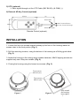
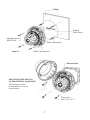
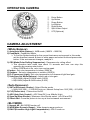
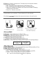
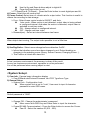
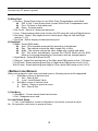
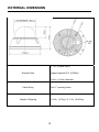
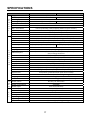
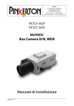
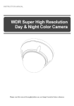
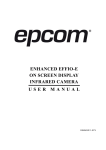
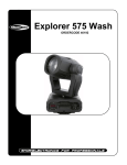
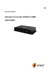
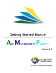
INSTRUCTION MANUAL WDR Super High Resolution Day & Night Color Camera CV650WDR IMPORTANT SAFETY INSTRUCTIONS 1. 2. 3. 4. 5. 6. 7. 8. 9. 10. 11. 12. 13. 14. 15. 16. Read these instructions. Keep these instructions. Heed all warnings. Follow all instructions. Do not use this apparatus near water. Clean only with dry cloth. Do not block any ventilation openings. Install in accordance with the m anufacturer’s instructions. Do not install near any heat sources such as radiators, heat registers, stoves, or other apparatus (including amplifiers) that produce heat. Do not defeat the safety purpose of the polarized or grounding-type plu g. A polarized plug has two blades with one wider than the other. A gro unding type plug has two blades and a third grounding prong. The wid e blade or the third prong are provided for your safety. If the provided p lug does not fit into your outlet, consult an electrician for replacement o f the obsolete outlet. Protect the power cord from being walked on or pinched particularly at plugs, convenience receptacles, and the point where they exit from th e apparatus. Only use attachments/accessories specified by the manufacturer. Use only with the cart, stand, tripod, bracket, or table specified by the manufacturer, or sold with the apparatus. When a cart is used, use cau tion when moving the cart/apparatus combination to avoid injury from ti p-over. Unplug this apparatus during lightning storms or when unused for long periods of time. Refer all servicing to qualified service personnel. Servicing is required when the apparatus has been damaged in any way, such as power-su pply cord or plug is damaged, liquid has been moisture, does not oper ate normally, or has been dropped. CAUTION – THESE SERVICING INSTRUCTIONS ARE FOR USE B Y QUALIFIED SERVICE PERSONNEL ONLY. TO REDUCE THE RIS K OF ELECTRIC SHOCK DO NOT PERFORM ANY SERVICING OT HER THAN THAT CONTAINED IN THE OPERATING INSTRUCTION S UNLESS YOU QRE QUALIFIED TO DO SO. Use Certified/Listed Class 2 power source only. CONTENTS OF PACKAGE The package contains the following Camera in Housing ------------------------------------------------------------------1 Instruction Manual (This Document) --------------------------------------------1 Accessory Kit for Installing ---------------------------------------------------------1 Drilling guide label -------------------------------------------------------------------1 TABLE OF CONTENTS INTRODUCTION --------------------------------------------------------------------------------------- 4 CAMERA CONNECTIONS -------------------------------------------------------------------------- 5 INSTALLATION ----------------------------------------------------------------------------------------- 6 LENS ADJUSTMENT --------------------------------------------------------------------------------- 8 DC AUTO IRIS LENS --------------------------------------------------------------------------------- 8 OPERATING CAMERA ------------------------------------------------------------------------------- 9 CAMERA ADJUSTMENT ---------------------------------------------------------------------------- 9 EXTERNAL DIMENSION ---------------------------------------------------------------------------- 16 SPECIFICATIONS ------------------------------------------------------------------------------------- 17 3 INTRODUCTION The camera provided high-quality image using SONY Wide Dynamic 1/3” Super-HADII PS 960H CCD and digital signal processing LSIs. Features: • 1/3” Super-HADII PS 960H CCD • Super high-resolution of 650TV lines • 0.4 lux(Color), 0.04 lux(B/W), 0.001 lux(Low-Shutter) @ F1.4 Sensitivity • C/CS, back-focus cam for easy adjustment • Auto Electronic Shutter [1/60(1/50) ~ 1/100,000] and manual electronic shutter modes [1/60(1/50) ~ 1/10,000] • On Screen Display (OSD) • Auto and Manual white balance modes • Support Line-Lock external synchronization • Digital PTZ • Digital Effect (H/V reverse, 180 degree rotate, inverse, freeze) • 2D-NR, 3D-NR (DNR Demo) • Back Light Compensation • Back Light Masking (MAX. 15 area) • Excessive High-Light Compensation • Wide Dynamic Range (~x512) • Various Detection Method (zone detection, motion trace, face trace, mine area, absent detection, cross object counting, entrance counting) • Day & Night(Auto, Manual, External, Filter delay) • Various Alarm Method (Period, Snooze, Polarity Select) • Privacy Mask or Mosaic (MAX. 15 area/4-point polygonal/transparency) • Scene Change Detection • Sens-Up (~x32) • White Pixel Remove • Frame Control (Auto, 1~7 sec) • System Lock (4-Digit password) • RS-485 Remote camera control • Compatible with Video, DC type lenses with OSD select • Quick connect for Video or DC lens with 4-pin connector • Operates in 12VDC or 24VAC • User Certified / Listed Class 2 power source only 4 CAMERA CONNECTIONS Connection Cable Description COLOR Description RED AC24V/DC12V WHITE AC24V/DC12V ORANGE ADKEY BROWN GND BLUE RS485(-) GREEN RS485(+) YELLOW ALARM OUT GRAY DN EXT-IN BLACK&WHITE DN EXT-OUT BLACK GND SKY BLUE UTP+(optional) PINK UTP- (optional) 1) External Day/Night Control : To select Day/Night mode using external equipment, by connecting control lines to the appropriate terminals. DAY&NIGHT OUTPUT (Black&White) Is the camera function that can turn on an external IR LED Lamp by detecting the sensitivity on the AGC level when the D&N mode is set "AUTO" on the OSD menu of the camera Black&White DAY&NIG Black GND ● 5V/10mA : IR LED ON (NIGHT) ● 0V : IR LED OFF (DAY) DAY&NIGHT EXTERNAL INPUT (Gray) Is the camera function that can be switched to DAY Mode or NIGHT mode by receiving the D&N on/off signal from external light sensor or IR LED LAMP. This needs the D&N Mode to be set to "External" on the OSD menu of the camera to work Black GND ● Close contact: NIGHT Gray DAY&NIGHT INPUT ● Open contact: DAY 2) Alarm Out Motion detection signals are output through this port. (YELLOW AND GND) Active state is configurable. 3) Power Input Terminal RED & WHITE : DC Power is recommended to use the DC power supply that can support inrush current over 0.75A 4) Camera Control GREEN : RS 485+ BLUE : RS 485- 5 5) UTP (optional) Video signal through out the UTP Cable (SKY BLUE(+) & PINK(-) ) 6) External AD Key Control (optional) 95mm 1m Black/GND GND Terminal/Brown 45mm AD Key Terminal/Orange 3mm White/AD output Remote Control (optional) INSTALLATION 1. Loosen the four torx screws located midway up the front of the housing leave the screws intact in the front portion. (Fig. 1) 2. Drill the mounting location, using the bottom of the housing as a Drilling guide label. (Fig. 2) 3. Attach the housing to the ceiling using suitable fasteners, M6x35 tapping screws are supplied only use if they are suitable. (Fig. 2) 4. Closing the housing using the loosen torx screws. (Fig. 3) Torx screws M5x10 (4x) Torx screws M5x10 (4x) Figure 1 Figure 2 6 Seal around the housing base tightly i Ceiling Drilling Guide Label Mounting Screw M6X35(4x) Plastic Anchor(4x) Figure 3 Rubber Washers(4x) Electrical box MOUNTING HOUSING TO AN ELECTRICAL BACK BOX The housing can also be mounted on a 4s or 2s electrical box. Torx screws UNC 8-32 x 0.75 7 LENS ADJUSTMENT Field of view: Adjust setting from Telephoto (T) to wide (W) field of View. Focus: Adjust lens focus from near (N) to infinity. DC AUTO IRIS LENS 2.6-6mm Image Size Focal Length Aperture Ratio Angular Field of View (Degree) 4-9mm 1/3” CCD 2.6-6.0mm 1 : 1.6 2.8~12mm 1/3" CCD 5% 5% DIAGONAL 2.6mm : 134.6 6mm : 59.2 4.0-9.0mm 1 : 1.6 5% 5% DIAGONAL 4mm : 92.4 9mm : 39.2 8 1/3" CCD 2.8-12mm 1 : 1.4 5% 5% 2.8mm : 119.9 12mm : 28.8 6-50mm 1/3" CCD 6.0-50mm 1 : 1.6 5% 6.9% DIAGONAL 6mm : 58.6 50mm : 7.1 OPERATING CAMERA ① ② ③ ④ ⑤ ⑥ ⑦ Enter Button Up Button Down Button Left Button Right Button Spot Video Output UTP(Optional) CAMERA ADJUSTMENT <White Balance> 1) Auto(Auto White Balance) : AWB mode (1800ºK ~10500ºK) 2) Push/Hold : Push&Hold Mode. To find the Optimal setting for the current luminance environment in this mode, set the direction towards a sheet of white paper and select Hold and press enter button. If the environment changes, readjust it. 3) CRS Mode(Color Rolling Suppression) : Decrease color rolling effect. This operation take some time about 10 seconds and user can stop this operation by pressing enter button. When CRS Mode is on, color tone can be weak. 4) Indoor : Set color temperature to indoor (3200ºK) 5) Outdoor : Set color temperature to outdoor (6300ºK) 6) FL(Fluorescent Light) : Set color temperature to fluorescent light fixed gain. 7) User(User Set White Balance) : Adjust red or blue gain. R(R-GAIN):Adjust R-GAIN value (0-255) B(B-GAIN):Adjust B-GAIN value (0-255) <Auto Exposure> 1) SHT(s)(Electronic Shutter) : Select Shutter mode. Auto(1/60(1/50) ~ 1/100,000 Auto run, Manual 8 step from 1/60(1/50) ~1/10,000). 2) FLC(Flicker-less) : Flicker-less On/Off. 3) AGC(Auto Gain Control) : AGC Gain(Off, Low, Middle, High) 4) Sens-Up(Slow Shutter) : Maximum Low-Shutter select. (x2-x32 and Off) 5) Offset Add : Force the picture to turn up at low luminance environment. <BLC/WDR> 1) Normal AE : BLC/WDR function off. 2) WDR(Wide Dynamic Range) : Wide dynamic range mode on. 3) EHLC(Excessive High Light Compensation) : EHLC mode on. 9 excessive lighting compensation is performed when the weighting on the high-brightness side is increased. 4) Auto(Auto Weighting BLC) : Auto weighting BLC on. 5) Spot(User Setting BLC area) : Spot metering mode on. Posi : OSD mode to adjust the position of the spot metering area. Size : OSD mode to adjust the size of the spot metering area. 6) Zone(Preset BLC area) : Fixed metering area mode. (1-9). <Mask> 1) Mask: Select mask area(1-15). 2) Func: Select mask function.(Privacy, BLM, Both, Off). Privacy : Area to screen on the display. BLM : Back Light Mask. Selected BL Mask area that will be except of the auto exposure If there is a high light installed in a limited environment such as an apartment parking garage or gas station entrance, removing the high light makes it possible to view car license plates efficiently. Both : Privacy function and BLM function on. Off : Function off. 3) Edit : Mask area edit. Edit mode take effect during Func not Off. Size : adjust the size of the Privacy and BLM mask area. Posi : adjust the position of the Privacy and BLM mask area. Tilt : adjust tilting of Privacy and BLM mask area. Color: Select Privacy and BLM mask (0-14). Transparency: Select Privacy mask transparency (Default 3/0-3). Mosaic: Select Privacy and BLM mask mosaic On/Off Adj. Mosaic: Adjust Privacy and BLM mask mosaic level (0-31). <Detection> Func : Detection function selection. Sens Down : Adjust to Motion Sensitivity using left/right Buttons. 1) OFF : Detection function off. 2) Zone : Area motion detection mode. Zone : Select Motion detection zone (Zone1-4). Func : Select Motion detection on/off. Size : Press Enter button to adjust the size of the Motion detection area. Posi : Press Enter button to adjust the position of the Motion detection area. Link Zoom : Select Motion detection with D-PTZ function that On/Off . When the motion triggered in the area, move to the area with D-PTZ. 3) Motion Trace : Motion trace mode on. Tracks an object through a scene and generates an alarm. 4) Face Trace : Face Trace mode on. Tracks face through a scene and generates an alarm. Sens Down : lower value is more widen the scope to judge face. (0~127) Min Size : Minimum face size configuration (0 : minimum face size is to none) 10 The result of face trace can be inaccuracy. 5) Mine : Mine area mode. By this function, User can draw motion detection area with free dotting Set Mine : Press the Enter button to Set Mine mode. < > : Move : Mine Zone move using the Left and Right buttons. UP:Set : Mine Zone setting using the Up button. DN:Clr : Mine Zone clear using the Down buttons. ENT:End : Press the Enter button to set Mine mode end. Clr All : Press the Enter button to set Mine area clear. Display : Select Mine Display On/Off. 6) Absent : Press the Enter button to Absent detection mode. Absent : Detect object appeared or removed the scene. Sens Down : Adjust sensitivity of Absent check(0-255). In low luminance environment, the accuracy is down of the result. Because object color is effect to auto exposure, the accuracy is down of the result If the object is too big, the accuracy is down of the result. 7) Cross : Cross counting mode. Zone : Select Cross Zone using the Left and Right buttons (Zone 1, Zone 2). Size : Adjust the size of the Cross zone. Posi : Adjust the position of the Cross zone. Direction : Select Cross Direction. Alarm Cnt : Set alarm out cross count. Alarm count number is delaying number before output alarm. Reset Cnt : Cross count reset. If object is passing so fast through the two area, counting is not operating. In this case, adjust to expand space between two area or decrease size of area. If passing object is too long, counting result can be inaccuracy. In this case, adjust to expand space between two area or adjust to decrease size of area. If two object passing the area in the same time, the results can be inaccuracy. 11 8) Entrance : Entrance counting mode. The object move in through the entrance, counting number increases. Size : Press Enter button adjust the size of the Entrance zone. Posi : Press Enter button adjust the Position of the Entrance zone. Alarm Cnt : Set alarm out entrance count. Alarm count number is delaying number before output alarm. Reset Cnt : Entrance count reset. Crossing object is not considered. / Several objects will not be detected. If the distance is increases between the camera and entrance, the result can be inaccuracy. The distance is too long Several Object Crossing Object Camera Installed at the ceiling Crossing object is none One object is passing. <Picture/DNR> 1) Sharpness : Adjust sharpness of outlines (0~15) 2) Resolution : Select high resolution mode (Low/Mid/High) 3) 2D-NR : Select 2D noise reduction level (0~6) 2D-NR : Noise reduction on a frame 4) 3D-NR : Select 3D noise reduction level (0~31) 3D-NR : Noise reduction through the several frame 5) DNR Demo : Select DNR Demo Display On/Off using the Left and Right Buttons None DNR Effect Display DNR Applied Display <Effect/Special> 1) d-Effect(Digital Effect) : Select digital Flip/Rotate state (Off/Rotation/Mirror/V Flip ) 2) Nega : Select negative color state(on/off) 3) d-PTZ (Digital Pan, Tilt, Zoom) : Adjust d-PTZ. Func : Press the Enter button to turn digital zoom on/off. Zoom : Use the Left and Right buttons adjust to digital zoom(0-255). Pan&Tilt : Press the Enter button to access the Pan&Tilt. Use the Left and Right buttons adjust to digital pan 12 Use the Up and Down buttons adjust to digital tilt Press the Enter button to exit. PT Reset(Pan & Tilt Reset) : Press the Enter button to reset digital pan and tilt. 4) Freeze : Select the still mode on/off 5) Frame Control: Select term of refresh rate for output video. This function is useful to reduce the recording to data storage. Func : Select frame control mode to ON/OFF, and Auto. Auto mode : When motion is not detected, output video is being refresh in configured interval. And when the motion is detected, output video is switched to real time video. ON : Always refresh in configured interval. OFF : Always real time video. Renewal(sec) : Select an interval between two frame. When object start moving, The output video possible to cut a little time. 6) ScnChg/Unfoc : Select scene change/unfocus detection On/Off . Inform that whether scene have been changed or not. Detect breaking or changing in the watching scene (Spray, Screen Camera, Changing Scene…) This function is linked with alarm out In low luminance environment, the accuracy is down of the result. In very low luminance environment, operation is not be performed. It is not be performed when moving object is exist. <System Setup> 1) Cam Info : Camera basic information display Cam ID/Baud rate/Protocol/Firmware Ver./CCD Type/Lens Type 2) General Setup System Lock : Configuration Lock. When system lock is set to “Lock”, User must to input 4-character password to enter OSD menu. Default password is “0000”. Change PID : Change the administrator’s password Move cursor with OSD Key and Press Enter to input the character. Comm(RS 485 Communication) : Press the Enter button to access the Comm. Cam ID : Select the camera ID (001 - 255). 13 Baud Rate : Select serial communication speed (2400/4800/9600/19200). Protocol : RS-485 protocol. (COMMAND/FASTRAX/PELCO-D/Pelco-D) Title : Edit camera title. Title ☞< > Site_0 A ENT:Del B ABCDEFGHIJKLM NOPQRSTUVWXYZ abcdefghijklm nopqrstuvwxyz -. 0123456789 C Clear Cancel Accept A. Title B. Delete character C. Character table D. Command line - Clear : Clear Title - Cancel: Cancel editing - Accept: Save Title D Display : Display item select. Cam ID : Camera ID display On/Off. Title : Title display On/Off. Alarm . Period : Alarm out period (5sec/10sec/20sec/30sec/1min/5min/Cont.) Snooze : Alarm out snooze(Off/5sec/10sec/20sec/30sec/1min/5min) Active pol : Alarm output active state configuration. (Low, High) System Init Cancel : Back to General Setup Menu. Confirm : Initialize all data. (Factory Default) 3) Lens Iris : DC, Video, Manual Lens selected Iris : adjust AE Speed DC lens and video lens can adjust AE Speed Normal AE Ref (Auto Exposure Reference Level) : Press the Enter button to access the AE Ref. Ref Lvl : Adjust AE base reference level. WDR Ref : Press the Enter button to access the WDR Ref. Ref Lvl : Adjust the WDR long-time control Base Reference Level. 4) LLC(Line Lock Control) : Press the Enter button to access the Line Lock mode. Func : Select Line Lock function On/Off using the Left and Right buttons. Phase : Adjust Line Lock sync phase using the Left and Right buttons. (0~100) 14 Activate only AC power inputted. 5) White Pixel Det Exe : Press Enter button to turn White Pixel Compensation mode Start. ENT to Adj : Press Enter button to start White Pixel Compensation start. Proc : Process to find white pixel. Done : Process ended Det Count : Result of white pixel detection. Func : Select erasing white pixel function On/Off using the Left and Right buttons. Det Level : Select the judgment level of white pixel using the Left and Right buttons (1~16) Det View : Select display of detected white pixel. 6) Day/Night Mode : Select D&N mode. Auto : Filter operates automatically according to brightness. Day : The camera outputs the video image only in color. Night : The camera outputs the video image only in black and white. Ext : This menu automatically converts the COLOR Mode into the B/W Mode or vice versa depending on illumination with an external sensor. Night Mode : Select B/W Burst On/Off Delay(s) : Adjust the working time of the filter when D&N mode is Auto (1-60 sec). D>N Level : Select switching level Day to Night when D&N mode is Auto (0-15). N>D Level : Select switching level Night to Color when D&N mode is Auto (0-15). <Bottom Line Menus> When user entered in main menu and sub-menus, following menus will be appeared. I. Main Manu (menu in bottom lines) A. Exit : Save & Exit. B. Load : Load Default Value. II. Sub Menu (menu in bottom lines) A. Return : Return to previous menu. B. Exit : Save & Exit 1) Exit Menu Save&Exit : Current environment values save. Exit : Disappear menu osd. 2) Load Default Setup Yes : Load default to current configuration. and return to previous menu. No : No operation, and return to previous menu. 15 EXTERNAL DIMENSION 0.1 in. (2.5mm thick), Window Size impact-resistant P.C (LEXAN) 3.93 in. (10cm) diameter Cable Entry Weight / Shipping One 1" opening holes 1.54 lb. (0.7kg) / 2.11 lb. (0.96 kg) 16 SPECIFICATIONS MODEL G E N E R A L F U N C T I O N P O W E R E T C Image sensor Effective pixels Scanning system Scanning frequency Sync. system Resolution Min. illumination Video output S/N Ratio Camera Control White Balance Exposure BLC/WDR AGC Control Shutter Speed Sens‐Up Day/Night Video Analytics D‐Zoom DNR Privacy Zone Camera Title Display Cam ID Effect Bad Pixel System Lock Frame Control Language Other Function NTSC Power source Power consumption Power input Video output Auto iris output Lens mount Lens type Operating Temp. Operating humidity External dimension PAL 1/3" Super‐HADII PS 960H CCD 976x494 976x582 2:1 interlace 15.734KHz(H), 59.94Hz(V) 15.625KHz(H), 50Hz(V) Internal / Line lock 650 TVL 0.4 Lux (COLOUR), 0.04 Lux (B/W), 0.001 Lux (Low‐shutter) 1.0 Vp‐p (75 ohm, composite) 50dB (AGC OFF) RS485 (Faxtrax, Pelco D, Pelco P) Auto / CRS / Push&Hold / Indoor / Outdoor / FL / User Auto / Manual Shutter / Flickerless/ Low Light Control / Offset Add EHLC / AUTO / SPOT / ZONE/ BLM WDR: x512 (Level Adjust) Low / Middle / High / Off 1/60‐1/10,000 (Auto:1/100,000) 1/50‐1/10,000 (Auto:1/100,000) x32 Auto / Day / Night / Ext Zone / Motion trace/ Face trace/ Minefield/ Absent / Cross / Entrance/ Scene Change Detection ~ x256(Zoom) / D‐PTZ Support 2DNR, 3D NR :Gain Adjust, DNR Demo Max 15 (Tilt, Color, Transparency, Mosaic) Alpha Numeric On / Off (Cam ID, Title) 001~255 V‐Flip / Mirror / Rotation / Nega&Posi / Freeze / Sharpness Adj/Done (Max 64 point), Detected pixel display Lock/Unlock (need Password input when Locked) Auto, Off ~ 7Sec( Use for saving storage) English Admin Password, Alarm Setting(Period, Snooze, Polarity) DC 12V / AC 24V ± 10% 4.5 Watts 2‐Pin Terminal block BNC, UTP (optional) 4‐Pin mini din jack (standard connection) Fixed Mount 2.8mm~12.0mm/F1.4 D&N DC IRIS Vari‐Focal Lens ‐10ºC to +50ºC Less than 90% 146 (W) x 114 (H) x / Weight : 770g 17 5030xxxxA 18