1
EMS855 AMF AC Genset Controller User Manual This document applies to Product 9001-0079 Build Version 3600-0155 Firmware Version 5000-0084 Version History: S. No. Version No. Changes Made Date Modified Modified By 1 2 3 www.ems.gen.nz The information contained in this document is copyright, and shall not be reproduced without the written authority of EMS ©2010 Approved By EMS 855 GENSET CONTROLLER Contents 1. 2. 3. 4. Introduction ............................................................................................................................... 4 Benefits ..................................................................................................................................... 4 Physical Form ............................................................................................................................. 5 Functions ................................................................................................................................... 6 4.1 System ............................................................................................................................... 6 4.2 Engine Monitoring ............................................................................................................... 6 4.3 Generator Monitoring.......................................................................................................... 8 4.4 Mains AC Monitoring ........................................................................................................... 8 4.5 System LED Indications ........................................................................................................ 8 4.6 Transfer Control LED Indications ........................................................................................... 9 4.7 System LCD Displays ............................................................................................................ 9 4.8 AC Inputs.......................................................................................................................... 10 4.9 Analog Inputs.................................................................................................................... 10 4.10 Digital Inputs .................................................................................................................... 10 4.11 Outputs............................................................................................................................ 11 5. Operation ................................................................................................................................ 12 5.1 Buttons ............................................................................................................................ 12 5.2 LEDs ................................................................................................................................ 13 5.3 Initial Power Up ................................................................................................................ 14 5.3.1 Ready ........................................................................................................................... 14 5.3.2 Mode Selection ............................................................................................................. 14 5.4 Manual Operation ............................................................................................................. 15 5.4.1 To start the genset ......................................................................................................... 15 5.4.2 To stop the genset ......................................................................................................... 16 5.4.3 Autostart Engine Control ................................................................................................ 16 6. Display Operation ..................................................................................................................... 18 6.1 When the genset is running ................................................................................................ 18 7. Alarms and Warnings ................................................................................................................ 21 7.1 Inputs Electrical Specification ............................................................................................. 26 7.2 Outputs Electrical Specification ........................................................................................... 28 8. Load Transfer and Contactor Operation ....................................................................................... 29 9. Speed Sensing .......................................................................................................................... 29 9.1 MPU ................................................................................................................................ 29 9.2 Magneto .......................................................................................................................... 30 9.3 Generator ........................................................................................................................ 30 9.4 Battery Charging Alternator ................................................................................................ 30 10. Battery Charging Alternator Excitation .................................................................................... 31 11. Battery Voltage Monitoring and Charging Detection ................................................................. 31 12. Set-up ................................................................................................................................. 32 12.1 Navigating in the setup menu ............................................................................................. 32 12.2 System Column ................................................................................................................. 33 12.3 Engine Column .................................................................................................................. 34 12.4 Timers Column .................................................................................................................. 38 12.5 Contactor A Column .......................................................................................................... 39 12.6 Start/Stop Column............................................................................................................. 39 12.7 AC Setup Column .............................................................................................................. 40 12.8 AMF Setup Column ............................................................................................................ 40 12.9 AGF Setup Column ............................................................................................................ 41 12.10 Testing Column ................................................................................................................. 42 Confidential www.ems.gen.nz Page 2 EMS 855 GENSET CONTROLLER 12.11 Manual Column ................................................................................................................ 42 12.12 Room Temp Column .......................................................................................................... 42 12.13 Aviation Light Column (Not protected against prolonged power loss) ...................................... 43 12.14 I/O Config Column ............................................................................................................. 43 12.15 Comms (Communications) Setup Column............................................................................. 44 12.16 Log Viewer Column............................................................................................................ 45 13. Communications................................................................................................................... 45 13.1 Unit General Specifications................................................................................................. 45 14. Installation and Wiring .......................................................................................................... 48 14.1 Connector Detail ............................................................................................................... 49 15. Trouble shooting .................................................................................................................. 51 16. Wiring Options ..................................................................................................................... 54 Confidential www.ems.gen.nz Page 3 EMS 855 GENSET CONTROLLER EMS855 AMF AC GCU 1. Introduction The unit is a controller for mid-engine Gensets with Automatic Mains Failure (AMF) functionality sold in the private market segment. The unit incorporates Manual, Autostart Start and AMF Autostart initiated start and stop sequencing, monitors engine and alternator operating parameters and provides both engine and alternator protection, in a single integrated package. The Mains and Alternator status and operating parameters are shown by scrolling screens on a backlit Graphics LCD. Alarms and warning are also shown on the LCD and supplemented by status LEDs and a sounder output. The unit provides comprehensive monitoring of the engine operating parameters and provides automatic shutdown of the set in the event of damaging conditions. In addition to standard engine safety protections the unit monitors battery voltage, battery status, charging conditions, coolant level and temperature, fuel level, canopy temperature, oil pressure and temperature, engine speed and operating hours. On the Alternator side, the unit monitors and displays 1 or 3 phase voltages, for L-N and L-L. It monitors the operating frequency, 3 individual phase currents, Average PF, KVA, KVAr for each phase and Alternator total. It maintains 3 phase Power meter functions which comprise, Total Mains KWH, Total Alternator KWH and Total Alternator KVArH, The alternator incorporates several protection features which include Over-load, Over-current, Load imbalance, and IDMT protection. In the factory environment, the unit is configured by cloning through a Personal Computer (PC) system. Field specific parameters can be adjusted by using the front panel buttons and an inbuilt menu system. 2. Benefits Reduces system cost: o Integrates engine gauges and AC metering into one unit. o Minimises control panel wiring offering reduced material and labour costs. Reduces warranty costs by providing comprehensive engine and generator protection and a maintenance due timer. Flexibility, the unit can be customised by PC cloning for individual genset model characteristics and fitments. Includes communication ports for remote monitoring applications, dual station operation and companion auxiliary units. Inbuilt data logs provide operating history in the event of engine or alternator failure. Confidential www.ems.gen.nz Page 4 EMS 855 GENSET CONTROLLER 3. Physical Form Front View Rear View Confidential www.ems.gen.nz Page 5 EMS 855 GENSET CONTROLLER 4. Functions 4.1 System Function Description Protection Shutdown Automatic preventative engine and genset shutdown in the event of abnormal operating conditions with optional configuration parameters and clear LCD status messages Manual Start In response to the front panel pushbutton, the unit performs a fully sequenced engine start with optional configuration parameters and clear LCD status messages Manual Stop In response to the front panel pushbutton, the unit performs a fully sequenced engine stop with optional configuration parameters and clear LCD status messages Auto Start / Auto Stop In response to a digital input, the unit performs a fully sequenced engine start or stop with optional configuration parameters and clear LCD status messages. AMF Start In response to a mains failure event, the unit performs a fully sequenced engine start with optional configuration parameters and clear LCD status messages AMF Stop In response to a mains restored event, the unit performs a fully sequenced engine stop with optional configuration parameters and clear LCD status messages Emergency Stop In response to a digital input, the unit performs a fully sequenced engine stop with optional configuration parameters and clear LCD status messages Manual Transfer Control Manually initiated and automatically sequenced A and B contactor control with optional configuration parameters and clear LCD status messages Automatic Transfer Control Automatically initiated and sequenced A and B contactor control with optional configuration parameters and clear LCD status messages 4.2 Engine Monitoring Function Over / Under Speed Confidential Description Monitors engine speed with optional configuration parameters and clear LCD status messages. This ensures the engine speed remains within configured limits. Exceeding these limits will result in automatic engine shutdown to prevent damage. www.ems.gen.nz Page 6 EMS 855 GENSET CONTROLLER Function Lubrication Oil Pressure Lubrication Temperature Description Monitors engine oil pressure with optional configuration parameters and clear LCD status messages this ensures the oil pressure remains within configured limits. Exceeding these limits will result in automatic engine shutdown to prevent damage. Oil pressure monitoring can be from an oil pressure switch, or a resistive oil pressure sensor, or both. Oil Monitors engine oil temperature with optional configuration parameters and clear LCD status messages this ensures the oil temperature remains within configured limits. Exceeding these limits will result in automatic engine shutdown to prevent damage. Coolant Temperature Monitors coolant temperature with optional configuration parameters and clear LCD status messages this ensures the coolant temperature remains within configured limits. Exceeding these limits will result in automatic engine shutdown to prevent damage. Coolant Level Monitors radiator water level and provides clear LCD status messages. Automatic engine shutdown if radiator water is low. Battery Voltage Monitors engine battery voltage with optional configuration parameters and clear LCD status messages this ensures the battery voltage remains within configured limits. Battery Charging Monitors engine battery charging during standby and operation and shows the status with clear LCD status messages. Warnings are given if charging is under or over charging. Fuel Level Monitors engine fuel level with clear LCD status messages. Low fuel level will result in automatic engine shutdown to prevent damage. A fuel loss warning and event log are included. Canopy Temperature Monitors engine canopy temperature with optional configuration parameters and clear LCD status messages this ensures the engine canopy temperature remains within configured limits. Exceeding these limits will result in automatic engine shutdown to prevent damage. Running Hours Records engine run hours with clear LCD status messages. Service Timer A service timer is incorporated to ensure proper service schedules are maintained. The service message is displayed on the LCD at the pre-programmed times. An event log is maintained for service due and service taken. Confidential www.ems.gen.nz Page 7 EMS 855 GENSET CONTROLLER 4.3 Generator Monitoring Function Description AC Phase Voltage Monitors 1, 2 or 3 phases of AC voltage with optional configuration parameters and clear LCD status messages. Measurements include L-N and L-L. AC Phase Current Monitors 1 or 3 Delta phases of AC current with optional configuration parameters and clear LCD status messages. Uses externally fitted 5A Shunts. AC Phase Frequency Monitors 1, 2 or 3 phases of AC Frequency with optional configuration parameters and clear LCD status messages. AC Phase Reversal Monitors Alternator AC for Phase reversal with optional configuration parameters and clear LCD status messages. AC Loading Monitors AC load as a percentage of full load with optional configuration parameters and clear LCD status messages. AC Power Metering Monitors AC power output (KW, KVA, KVAr, KWH, KVArH and Avg PF) with optional configuration parameters and clear LCD status messages. 4.4 Mains AC Monitoring Function Description AC Phase Voltage Monitors 1, 2 or 3 phases of AC voltage with optional configuration parameters and clear LCD status messages. Measurements include L-N and L-L. AC Phase Frequency Monitors 1, 2 or 3 phases of AC frequency with optional configuration parameters and clear LCD status messages. AC Phase Reversal Monitors Mains AC for Phase reversal with optional configuration parameters and clear LCD status messages. Mains Failure Monitors AC failure with optional configuration parameters and clear LCD status messages. Includes Under and Over Voltage, Under and Over Frequency, 4.5 System LED Indications Function Description Alarm Red LED indication of system alarm. Manual Mode Green LED indication that the unit is in Manual Start Mode. Confidential www.ems.gen.nz Page 8 EMS 855 GENSET CONTROLLER Function Description Auto Mode Green LED indication that the unit is in Automatic Start Mode Test Mode Green LED indication that the unit is in Test Mode 4.6 Transfer Control LED Indications Function Description Alternator Available Phase 1 Red LED indication that the Alternator phase 1 voltage is available. Alternator Available Phase 2 Yellow LED indication that the Alternator phase 2 voltage is available. Alternator Available Phase 3 Blue LED indication that the Alternator phase 3 voltage is available. Alternator Available Green LED indication that the Alternator is available for the load. Alternator on Load Green LED indication that the Alternator is on load. Mains AC Available Phase 1 Red LED indication that the mains phase 1 voltage is available. Mains AC Available Phase 2 Yellow LED indication that the mains phase 2 voltage is available. Mains AC Available Phase 3 Blue LED indication that the mains phase 3 voltage is available. Mains AC Available Green LED indication that the mains is available for load. Mains AC on Load Green LED indication that the mains is on load. 4.7 System LCD Displays Function Description Setup menu System configuration menus Start Up Clear step-by-step start up sequencing messages Shutdown Clear step-by-step shutdown sequencing messages Transfer Clear step-by-step load transfer messages Confidential www.ems.gen.nz Page 9 EMS 855 GENSET CONTROLLER 4.8 AC Inputs Function Description 3 Phase Mains AC Voltage Mains AC voltages. 3 Phase Alternator AC Alternator AC voltages. Voltage 3 Phase Alternator Current Alternator AC currents via external 5A CTs. 4.9 Analog Inputs Function Description Speed Engine speed from MPU or battery charging alternator. Lubrication Oil Pressure Engine oil pressure. Exciting current approx 13mA Lubrication Temperature Oil Engine oil temperature. Exciting Current approx 5mA Coolant Temperature Engine coolant temperature (Air or Water). Exciting current approx 5mA Fuel Level Engine fuel level. Exciting current approx 13mA Canopy Temperature Engine canopy temperature. Exciting Current approx 5mA Coolant Level Engine Radiator level. Exciting frequency 500Hz Battery Voltage (Internal) Battery Voltage is measured internally from DC supply point. 4.10 Digital Inputs Function Auto Start / Stop Input Description Auto start. Close to common. Current limited 10mA at 10V Emergency Stop Input Emergency engine stop. Selectable Open or Close to common. Current limited 10mA at 10V Oil Switch Input Oil Pressure Switch sensor. Close to common. Current limited 10mA at 10V Digital Input 1 Configurable. Default = Bypass. No logic control but full instrumentation available. Digital Input 2 Configurable. Default = Canopy door open. Confidential www.ems.gen.nz Page 10 EMS 855 GENSET CONTROLLER Function Description Close to common. Current limited 10mA at 10V Digital Input 3 Configurable. Default = Fire. Shutdown genset and open both contactors. Close to common. Current limited 10mA at 10V Digital Input 4 Configurable Default = BypassSW. Status, Warning, Alarm, PC programmed message. Close to common. Current limited 10mA at 10V 4.11 Outputs Function Description Excitation Output Alternator excitation control and feedback. 200mA Pulsed Preheat Output Open drain engine preheat control. Open Drain 300mA /36V DC Fuel Output Open drain fuel solenoid control. Open Drain 300mA /36V DC Crank Output Open drain engine crank control. Open Drain 300mA /36V DC Idle Output Open drain engine idle control. Open Drain 300mA /36V DC Sounder Output Open drain audible sounder control. Open Drain 300mA /36V DC User Output Open drain user control. Open Drain 300mA /36V DC Contactor A Output Open drain transfer contactor A control. Open Drain 300mA /36V DC Contactor B Output Open drain transfer contactor B control. Open Drain 300mA /36V DC Confidential www.ems.gen.nz Page 11 EMS 855 GENSET CONTROLLER 5. Operation Front Layout 5.1 Buttons Button Function Description Mode button MODE Used to change mode between manual, auto and test Start button / Menu Previous START 1. Used to initiate generator start sequence 2. Used as system menu previous button Stop button / Menu Next STOP 1. Used to initiate generator stop sequence 2. Used as system menu next button Accept button / Setup Menu Entry 1. Used to accept system events and silence the sounder 2. Used to enter the Setup mode Confidential www.ems.gen.nz Page 12 EMS 855 GENSET CONTROLLER Button Function Description Mains Transfer Button Used to start transfer sequence of load from genset to mains Genset Transfer Button Used to start transfer sequence of load from mains to genset Screen Scroll up / Setup menu up Button 1. Screen Scroll up Button 2. Used as the system menu up and value increment button Screen Scroll down / Setup menu down Button 1. Screen Scroll up 2. Used as the system menu down and value decrement button 5.2 LEDs Button Function Description Alarm Indicates system alarm Genset Available Indicates that the genset is available to go on load Genset On Load Indicates that the genset is currently on load Alternator Phase Status Indicates the phases which are available from the genset 1. Red – Phase 1 2. Yellow – Phase 2 3. Blue – Phase 3 Mains Available Indicates that the mains supply is available to go on load Mains On Load Indicates that the mains supply is currently on load Confidential www.ems.gen.nz Page 13 EMS 855 GENSET CONTROLLER Button Function Description Mains Supply Phase Status Indicates the phases which are available from the mains 1. Red – Phase 1 2. Yellow – Phase 2 3. Blue – Phase 3 Manual Mode Indicates that the system is in manual mode Auto Mode Indicates that the system is in automatic mode Test Mode Indicates that the system is in test mode 5.3 Initial Power Up On power up, the unit displays the Logo. The unit then displays the Serial number, Application Code and Firmware version. After the initialisation process is complete, the unit waits for a Start request (Start Button, AMF failure or Auto Start Input), during which time it will display ‘READY’. 5.3.1 Ready When the unit is in READY all measuring systems and display systems are turned on. The unit remains on for 1 minute and if the genset is not started in that time the unit goes into sleep mode to conserve battery power. In this mode the unit wakes periodically to check for any unusual conditions and if it finds none it goes back to sleep, otherwise it alarms accordingly. Where ‘awake’ mode has been selected the system parameters are continuously scrolled. Any activity on the buttons immediately wakes the unit and the appropriate action is taken. Pressing the STOP button while the unit is asleep immediately wakes the unit and scrolls all engine and generator parameter screens. This allows reading of battery voltage, fuel level, run hours KWH etc. 5.3.2 Mode Selection The unit may be operated in Auto, Manual, Test or Stop modes. The mode is selected by pressing the mode button. The mode is indicated on the LCD and the LED associated with the mode buttons. The engine can be stopped with the Stop button in MANUAL, AUTO or TEST modes. Confidential www.ems.gen.nz Page 14 EMS 855 GENSET CONTROLLER In MANUAL mode the unit responds only to the manual push button and may control A and B contactors if these options have been enabled. In the AUTO mode, the unit responds to the autostart input or Remote Starts and controls A and B contactors. In TEST mode the engine responds only to the manual start button and runs for a preset test time if configured. Contactors are not controlled. 5.4 Manual Operation 5.4.1 To start the genset START When the display is showing READY, press the start button momentarily to start the genset. The READY state implies the engine and generator parameters are as expected for a stationary genset. If the conditions are not as expected, an appropriate warning or alarm is displayed on the LCD. The warning or alarm condition must be cleared before the genset can be started. The unit will perform the starting sequence as follows: FUEL-ON. o If ETR (Energise To Run) fuel control is configured, the unit will control the fuel output and display FUEL ON and the proceeds to the CRANK state. o For ETS (Energise To Stop) the sequence does not activate the output but proceeds after a short delay to the CRANK state. CRANK. o The crank output is activated and the display shows ‘Cranking’ with a count down time. o The crank output is deactivated when the unit has detected a speed signal above the crank disconnect speed specified in the settings, or has detected oil pressure above the minimum oil pressure specified in the settings or Excitation is present o If the genset does not start, the LCD will show ‘Stopping’, control the Fuel and Crank outputs accordingly, and return to READY. No retries are done. o If the unit looses power due to battery voltage drop during cranking, and the engine fires, then on regaining adequate battery voltage, the unit will continue to allow the engine to run. This typically ONLY happens with ETS fuel systems. RUN UP. o When the engine starts, the display shows ‘Run Up’ with a count down in seconds. This allows the engine measurement system to stabilise. Over speed and loss of speed signal are the only parameters checked during Run Up. Confidential www.ems.gen.nz Page 15 EMS 855 GENSET CONTROLLER WARM UP o Allows the engine to stabilise at full speed before going on load. Oil pressure and Over-speed are monitored. The display shows ‘Warm Up’ with a countdown time. RUNNING o The display shows ‘Running’. Operating parameters are scrolled onto the display. 5.4.2 To stop the genset STOP Push the button briefly. The unit will perform a stopping sequence as follows: STOPPING o The display will show ‘Stopping’ with a countdown time. o If ETR fuel control has been selected the Fuel output will be de-energised. o If ETS fuel control has been selected then the Fuel output will be energised for the Max Fuel Time or until the engine stops. The stopping process will retry if the engine fails to stop the first time. During the ‘ETS Rest period’ the Fuel output is deactivated. o The fuel output is controlled until the engine stops rotating and oil pressure decays. If the Oil Pressure has not decayed by the end of the ‘Max Fuel Time’, the fuel output is deactivated and the controller waits until the oil pressure has decayed, or for the remainder of the ‘Stop Time’. The speed must remain at zero and the oil pressure must be below the alarm set point for the ‘Stop Rest Time’ before the engine is considered stopped. o If the genset does not stop then the alarm output is activated and ‘STOP FAIL’ is displayed on the LCD. READY o The engine has stopped and is ready to start again as required. 5.4.3 Autostart Engine Control If the Autostart input is activated, the unit will initiate an Autostart sequence. The sequence is similar to the manual start and stop sequences above with the following additions. Confidential An adjustable Start Delay follows the Autostart input activation. This is usually configured to avoid nuisance starting. The Display shows “Starting” with a countdown value. For long start delays, the start time units may be set to minutes. If the autostart restores for more than the Start Restore time, then the start sequence is aborted. www.ems.gen.nz Page 16 EMS 855 GENSET CONTROLLER The unit cranks the engine for the crank time or until the engine fires. If the engine does not fire after the crank time, then the unit will repeat the crank procedure after waiting for the crank rest time. This cycle is repeated for the “Crank Retries” and if the engine has not started after the last cycle, a “Fail to Start” alarm is generated. The Start sequence now follows the manual starting sequence until the engine is running. During an Autostart run the LCD displays Auto in the top left of the display. The stopping sequence is initiated by deactivation of the autostart input. The engine does not stop immediately as there are three additional states in the Auto stopping sequence. “Run On” follows “Running” and is a provided as an adjustable delay to reduce nuisance stopping. The Contactor A & B Outputs remain activated and the Display shows “Run On” with a countdown value. If the autostart input is re-activated during “Run On” the unit returns to normal “Running” until the Autostart input is deactivated. “Cool Down” follows “Run On” and allows the engine and/or generator to cool down before stopping. The cool time is adjustable. At the start of “Cool Down” the Contactor A & B Outputs are deactivated, transferring the load to the mains. The display shows “Cool Down” with a countdown. If the autostart input is re-activated during “Run On” the unit returns to normal “Running” and Contactor A and B are activated. “Idle down” follows “Cool Down”. The engine runs at idle speed for the idle down time. If the autostart input re-activated during Idle Down, then the unit returns to the Warm Up state and continues its starting sequence from there in the normal manner. Pressing the Stop button in auto mode stops the engine immediately, deactivates the Contactor A & B Outputs, and changes the mode of the unit to Manual. Confidential www.ems.gen.nz Page 17 EMS 855 GENSET CONTROLLER 6. Display Operation 6.1 When the genset is running When the genset is starting and stopping, the display shows the state of the sequence together with the time remaining before the next state will commence. Once the genset is fully running or if the genset is stopped and in ‘READY’, the running parameters are displayed. This includes generator and engine parameters simultaneously on separate displays. The unit sequentially scrolls through screens as shown below Screen – 1 Screen – 2 Screen - 3 Screen – 4 Screen – 5 Confidential www.ems.gen.nz Page 18 EMS 855 GENSET CONTROLLER Screen – 6 Screen – 7 Screen –8 Screen – 19 Screen – 10 Screen – 11 Confidential www.ems.gen.nz Page 19 EMS 855 GENSET CONTROLLER Screen – 12 Screen – 13 Screen – 14 Screen – 15 Screen – 16 Screen – 17 Confidential www.ems.gen.nz Page 20 EMS 855 GENSET CONTROLLER Screen – 18 Screen – 19 Then returns to start scroll If Warnings or Alarms are present, the associated messages are included in the LCD scroll list, and are shown after the last screen has been displayed. 7. Alarms and Warnings In the event of abnormal operating conditions the unit will issue a warning or an alarm and shut the genset down as required. The LCD shows an appropriate message indicating the nature of the condition. To draw operator attention to the condition the flashing general alarm LED is used. In most cases, Warnings do not stop the genset and are self resetting. Alarms will normally stop the genset and require the operator to clear the alarm by pressing the Stop or Accept button. The genset can not be started if an alarm exists. Warnings are indicated by slow flashing of the alarm LED and displaying the appropriate message on the LCD as follows. Alarms are indicated by fast flashing of the ALARM LED and displaying the appropriate message on the bottom LCD. Message Oil Pressure Low Oil Temperature High Engine Temp High Coolant Temp High Confidential Function description The oil pressure went below the alarm setpoint while running. Check oil level and replenish. Check for blocked oil filter. The oil temperature went above the alarm setpoint while the engine was running. Check for over loading. Check cooling air flows, check coolant and oil level. The Engine / Coolant temperature went above the alarm setpoint while the genset was running. Check for over loading. Check cooling air flows, Check coolant level. www.ems.gen.nz Page 21 EMS 855 GENSET CONTROLLER Message Canopy Temp High Function description The Canopy Temperature went above the alarm setpoint. Check cooling air flows. Check for overloading. The Fuel Level is below the alarm setpoint. Fuel Level Low The engine is stopped to prevent air and dirt infiltration to the engine. Replenish the fuel. Fuel Loss The Fuel Level is unexpectedly going down while the genset is not running The battery voltage went above the setpoint. Battery Voltage High High battery voltage usually indicates that the battery charging alternator has failed and it is producing a voltage which might damage the battery, control relays or the controller. Engine shutdown is recommended to minimise the risk of damage and fire. Under Speed Over Speed Hirev Alarm Coolant Level Low Start Fail Stop Fail Belt Broken Oil-P Fault Oil-T Fault Confidential The engine was running below the under speed setpoint. Check for overloading. Check fuel system. The engine was running above the setpoint. Check governor system. Check power takeoff couplings. The speed signal indicates the engine is grossly over speed. Check Governor system. The radiator water level is below the required level. The water level needs topping up. The engine has failed to start. Check Fuel supply, check battery condition, check air filters. The engine has failed to stop. Check stop solenoid, check rack operation. If the belt break detector has been activated. Check the belts The Oil Pressure sensor system is not functioning as expected. Check oil pressure sensor and associated wiring. The Oil Temperature sensor system is not functioning as expected. Check oil temperature sensor and associated wiring. www.ems.gen.nz Page 22 EMS 855 GENSET CONTROLLER Message Eng-T Fault Can-T Fault Fuel-L Fault Function description The Engine Temperature Sensor is not functioning as expected. Check engine temperature sensor and associated wiring. The Canopy Temperature Sensor is not functioning as expected. Check the canopy temperature sensor and associated wiring. The Fuel Level Sensor is not functioning as expected. Check the Fuel Level Sensor and associated wiring. The Speed Sensing system is not working as expected. Speed Fault Check the associated speed sensor wiring and external influences such as poorly operating battery chargers and poorly filtered UPS systems connect to the load. Speed signal is unexpectedly present. Speed Detected Check the associated speed sensor wiring and external influences such as poorly operating battery chargers and poorly filtered UPS systems connected to the load. Check electrical safety earthing systems. Check associated communications networks are isolated and not part of an unexpected earth loop. Oil Pressure is unexpectedly present. Oil Detected Check the Oil Pressure Sensors and associated wiring. Check the Oil filter system is not blocked. Check the engine is not running with a failed speed sensing system. E-S Lock-out The emergency stop input has been activated. Deactivate the emergency stop input, and then press the stop button to clear this alarm. Can Door The canopy door input has been activated and the canopy door unexpectedly open Fire Alarm The Fire Alarm input has been activated. The genset will be shutdown as an emergency stop. Investigate the source of the alarm then press the stop button to clear this alarm Alarms are indicated by fast flashing of the alarm LED and displaying the appropriate message on the LCD. Message Oil Pressure Low Confidential Function description The oil pressure went below the alarm setpoint while running. Check oil level and replenish. Check for blocked oil filter. www.ems.gen.nz Page 23 EMS 855 GENSET CONTROLLER Message Oil Temperature High Engine Temp High Function description The oil temperature went above the alarm setpoint while the engine was running. Check for over loading. Check cooling air flows, check coolant and oil level. The engine temperature went above the alarm setpoint while the engine was running. Check for over loading. Check cooling air flows, Check coolant level. Canopy Temp High The Canopy Temperature went above the alarm setpoint. Check cooling air flows. Check for overloading. The Fuel Level is below the alarm setpoint. Fuel Level Low The engine is stopped to prevent air and dirt infiltration to the engine. Replenish the fuel. The battery voltage went above the setpoint. Battery Voltage High High battery voltage usually indicates that the battery charging alternator has failed and it is producing a voltage which might damage the battery, control relays or the controller. Engine shutdown is recommended to minimise the risk of damage and fire. Under Speed Over Speed Hirev Alarm Water Level Low Start Fail Stop Fail Oil-P Fault Confidential The engine was running below the under speed setpoint. Check for overloading. Check fuel system. The engine was running above the setpoint. Check governor system. Check power takeoff couplings. The speed signal indicates the engine is grossly over speed. Check Governor system. The radiator water level is below the required level. The water level needs topping up. The engine has failed to start. Check Fuel supply, check battery condition, check air filters. The engine has failed to stop. Check stop solenoid, check rack operation. The Oil Pressure sensor system is not functioning as expected. Check oil pressure sensor and associated wiring. www.ems.gen.nz Page 24 EMS 855 GENSET CONTROLLER Message Oil-T Fault Eng-T Fault Can-T Fault Fuel-L Fault Function description The Oil Temperature sensor system is not functioning as expected. Check oil temperature sensor and associated wiring. The Engine Temperature Sensor is not functioning as expected. Check engine temperature sensor and associated wiring. The Canopy Temperature Sensor is not functioning as expected. Check the canopy temperature sensor and associated wiring. The Fuel Level Sensor is not functioning as expected. Check the Fuel Level Sensor and associated wiring. The Speed Sensing system is not working as expected. Speed Fault Check the associated speed sensor wiring and external influences such as poorly operating battery chargers and poorly filtered UPS systems connect to the load. Speed signal is unexpectedly present. Speed Detected Check the associated speed sensor wiring and external influences such as poorly operating battery chargers and poorly filtered UPS systems connected to the load. Check electrical safety earthing systems. Check associated communications networks are isolated and not part of an unexpected earth loop. Oil Pressure is unexpectedly present. Oil Detected Check the Oil Pressure Sensors and associated wiring. Check the Oil filter system is not blocked. Check the engine is not running with a failed speed sensing system. E-S Lock-out The emergency stop input has been activated. Deactivate the emergency stop input, then press the stop button to clear this alarm. Fire Alarm The Fire Alarm input has been activated. The genset will be shutdown as an emergency stop. Investigate the source of the alarm then press the stop button to clear this alarm A-S Lock-out If the Stop button is pressed while running in auto mode, it is considered an emergency stop and the unit will stop the engine and enter the Autostart Lockout state. This prevents the engine from starting again, while the Autostart input remains activated. The Autostart Lockout state is self resetting upon deactivation of the Autostart input. If the engine was stopped for a real emergency, then the emergency stop switch should also be activated to ensure the Confidential www.ems.gen.nz Page 25 EMS 855 GENSET CONTROLLER Message Function description engine will not start inadvertently. If the unit is in the Autostart Lockout state, the engine can be restarted by pressing the Start button. This is not considered a manual start but rather a release from the Autostart Lockout condition. The contactors will be controlled in the appropriate way. AGF Phase Reversal The generator has a phase reversal or the wiring is incorrect AGF Low V1 Volts Voltage on Alternator Phase V1 is Low AGF Low V2 Volts Voltage on Alternator Phase V2 is Low AGF Low V3 Volts Voltage on Alternator Phase V3 is Low AGF High V1 Volts Voltage on Alternator Phase V1 is High AGF High V2 Volts Voltage on Alternator Phase V2 is High AGF High V3 Volts Voltage on Alternator Phase V3 is High AGF High Frequency Alternator frequency is high AGF Low Frequency Alternator frequency is low 7.1 Inputs Electrical Specification Input Type Comment Nominal 12VDC or 24VDC or Station Battery Supply Battery + Volts Power 0V Common Power Fuel Level Sensor Analog/Digital Suitable for either resistive or switch C.O.F senders Coolant Temperature Sensor Analog/Digital Suitable for either resistive or switch C.O.F. senders Canopy Temperature Analog/Digital Suitable for analog use with EMS08 temperature sensor or switch C.O.F input Oil Pressure Sensor Analog Suitable for either resistive or switch senders. Optionally for protection or display only. Oil Temperature Sensor Analog/Digital Suitable for either resistive or switch C.O.F senders Low Water Level Digital Confidential Max 6-36VDC 0VDC, Common Suitable for probe or switch input. Open Circuit = Active www.ems.gen.nz Page 26 EMS 855 GENSET CONTROLLER Input Type Comment Autostart Digital Suitable for switch input. Connect to 0V = Active Emergency Stop Digital Suitable for switch input. Connect to 0V = Active Oil Pressure Switch Digital Used for backup Oil Pressure protection. Configurable for N.O or N.C. operation Digital Input 1 Digital Suitable for switch input. Connect to 0V = Active Digital Input 2 Digital Suitable for switch input. Connect to 0V = Active Digital Input 3 Digital Suitable for switch input. Connect to 0V = Active Digital Input 4 Digital Suitable for switch input. Connect to 0V = Active Excitation Internal High Impedance input Battery Voltage Internal High Impedance GL1 Voltage GL2 Voltage GL3 Voltage GN Voltage I1 Amps I2 Amps I3 Amps ML1 Voltage ML2 Voltage ML3 Voltage Confidential Generator Phase 1 Volts Max 350VRMS Generator Phase 2 Volts Max 350VRMS Generator Phase 3 Volts Max 350VRMS Generator Neutral Max 350VRMS Phase 1 Amps Shunt Loop Max 5A peak Phase 2 Amps Shunt Loop Max 5A peak Phase 3 Amps Shunt Loop Max 5A peak Mains Phase 1 Volts Max 350VRMS Mains Phase 2 Volts Max 350VRMS Mains Phase 3 Volts Max 350VRMS www.ems.gen.nz Page 27 EMS 855 GENSET CONTROLLER Input MN Type Comment Mains Neutral Voltage SPA Max 350VRMS Speed A magnetic pickup input 3V – 70V peak at >500 to 10KHz Voltage SPB Speed A Battery Alternator input 2V to 70V peak at 20Hz to 1KHz Speed B magnetic pickup input 3V – 70V peak at >500 to 0KHz Voltage Speed B Battery Alternator input. Connect to common. SPCom Voltage Speed Common 0VDC 7.2 Outputs Electrical Specification Output Type Excitation Current Fuel Solenoid Open Drain Comment 200mA burst mode pulsed current controlled output. 300mA Open Drain protected coil drive. Max 36VDC This output is used to maintain the fuel solenoid activated for running or stopping duty. 300mA Open Drain protected coil drive. Max 36VDC This output is used to control the crank relay coil. The crank relay should be sized for the crank contactor current. It is recommended that the crank relay is located in the wiring loom near to the starter motor. This position removes the need for high current wiring to the control box and thus leads to lower cost. Crank Open Drain Contactor A Open Drain 300mA Open Drain protected coil drive. Max 36VDC Contactor B Open Drain 300mA Open Drain protected coil drive. Max 36VDC Sounder Open Drain 300mA Open Drain protected coil drive. Max 36VDC Common Alarm Open Drain 300mA Open Drain protected coil drive. Max 36VDC Spare Open 300mA Open Drain protected coil drive. Max 36VDC Confidential This output is used to switch the load from the mains. This output is used switch the load to the generator. This output is used for an external sounder or horn. www.ems.gen.nz Page 28 EMS 855 GENSET CONTROLLER Output Type Comment Drain 8. Load Transfer and Contactor Operation The unit provides for both Mains and Generator contactor control even though in many applications this function will not be used, instead an MCB is used to switch the generator to and from the load. Contactor outputs are controlled in both Manual and Auto operating modes. The Mains contactor output is controlled to deactivate the Mains contactor when the start button is pressed or the autostart input is activated. The time of opening can be selected to respond immediately on an autostart input or a start button press. It can also be delayed or when the genset is running and able to take load. The Generator contactor output will activate only after the Mains contactor has opened and only when the genset able to take load. The timing is controlled by the XFR DELAY configuration setting. If the genset was started by activating the Autostart input, then deactivating the input will move the sequence to the “Cool Down” state. During cool down the Generator contactor output is deactivated and after a delay the Mains Contactor output is controlled to reactivate the Mains contactor. Load transfer can also be initiated with the use of the ‘Mains Transfer’ and ‘Genset Transfer’ buttons which will initiate a transfer sequence in accordance with configuration parameters. 9. Speed Sensing The unit can obtain speed information from one of four sources. Magnetic pickup unit Battery charging flywheel magneto Generator output 50/60Hz if used for genset control Battery charging alternator 9.1 MPU The magnetic pickup unit usually counts teeth on the flywheel and is mounted in the bell housing. It is important to ensure the gap between the MPU face and the teeth is 1mm to 2mm, as this distance greatly affects the output of the MPU. The unit requires a minimum of 3VRMS at low speed to ensure proper crank disconnect. Setup requires calculating the number pulses per 10 revolutions and the calculated number is then entered into the menu system “Cal Value”. Calculate: Number of Teeth x 10 = Speed Pulses Per 10 Revolutions. Eg: 125 teeth x 10 = 1250. Enter the number 1250. Confidential www.ems.gen.nz Page 29 EMS 855 GENSET CONTROLLER 9.2 Magneto Battery charging flywheel magneto is similar to the MPU in that there is a fixed relationship between the engine speed and the number of pulses per revolution. The number of pulses per 10 revolutions must be calculated and entered into the menu system “Cal Value”. Calculate: Measure frequency at some standard RPM and Calculate as follows: Cal Value = (Freq x 600) / RPM. Eg: (100Hz x 600) / 1500 = 40 Enter the number 40 9.3 Generator If the unit is used in a genset application the speed source can be the generator 50/60 Hz output and is connected internally within the unit from the AC input connectors. AC should not be connected directly to the speed MPU / Magneto input. For correct crank disconnect the generator must be providing a detectable output at low speed and therefore the voltage at 300 RPM must be greater than 40VRMS. This can be affected by the AVR and must be confirmed to provide suitable signals and timing for proper crank disconnect. For setup the number of pulses per 10 revolutions must be calculated and entered into the menu system “Cal Value”. The generator output frequency and standard RPM must be known. Calculate Speed Calibration value as follows: Cal Value = (Freq x 600) / RPM. Eg: (50Hz x 600) / 1500 = 20 Enter the number 20. 9.4 Battery Charging Alternator A low cost speed source can be derived from the battery-charging alternator if fitted. It unfortunately is also the most troublesome, and not recommended for reliable and repeatable long-term service. The difficulties arise from the in-exact relationship of alternator output frequency and engine RPM. As a result of slippage and variable mechanical coupling both calibration and long-term stability are compromised. The ratio of crank pulley to alternator pulley is indeterminate, as it depends very significantly on where the coupling belt rides in the V grove. Belt tension plays a very significant role, as does belt wear and instantaneous belt loading. Immediately after starting an engine the alternator is required to re-charge the partially discharged battery. The loading on the alternator is very high and belt slippage is common as is belt set low in the V groove. The output frequency may be lower than expected. If speed calibration is performed at this time, the speed representation will be too low and subsequently as the load reduces on the alternator, the engine speed will appear to erroneously increase. Confidential www.ems.gen.nz Page 30 EMS 855 GENSET CONTROLLER The battery charging alternator output frequency and current RPM must be known. This is achieved by independently running the engine, and measuring the battery charging alternator frequency on the W (sometimes D+) terminal. Excitation must also be provided to ensure self-excitation and an adequate output signal. Some small variation in reported speed may result but this can be calibrated out later during engine commissioning. For setup the number of pulses per 10 revolutions must be calculated and entered into the menu system “Cal Value”. Calculate Speed Calibration value as follows: Cal Value = (Freq x 600) / RPM. Eg: (257Hz x 600) / 1500 = 102.8. Enter the number 103. 10. Battery Charging Alternator Excitation The battery charging alternator excitation system is implemented using a burst mode pulse system. This ensures reliable self-excitation while managing current consumption during standby, heat dissipation during fault conditions, and pulsing the battery-charging alternator prior to cranking for improved speed signal output. During standby and Ready, the alternator excitation is pulsed once per minute to maintain some level of residual magnetism in the alternator but still maintaining minimum power consumption. On receiving a start signal, the unit pulses the alternator excitation input with a burst of 200mA pulses. The pulse width is dependent on the battery voltage. This pulse burst establishes a definite magnetic field in the battery-charging alternator prior to cranking. This ensures a significant speed-sensing signal is generated for crank disconnect sensing. The alternator excitation is turned off and the engine is cranked without the usual alternator burden loading the cranking process. This aids easier starting. When the engine has fired and is running, more 200mA pulse bursts are applied. Given the alternator is rotating at more than the 3000RPM the alternator will achieve self-excitation. If self-excitation is not achieved this process will repeat for a few seconds before the excitation failed warning is given. Alternator excitation may also be used as a secondary crank disconnect signal for the case where the speed signal has failed immediately the engine starts to run. This feature can be disabled if not required by setting “Excite Dis” to NO. For systems where a battery-charging alternator is not fitted, turning off the excitation warning will disable the excitation system. 11. Battery Voltage Monitoring and Charging Detection A battery is considered charged if (assuming a 12V system. x2 for 24V) its terminal voltage is above 13.1Volts. Typically a fully charged battery has a terminal voltage of 13.6V, above this and the battery is being overcharged. During cranking the large discharge current will reduce the battery terminal voltage below 12.5V and the battery cannot increase the terminal voltage again without the assistance of a charger. This sequence provides a useful mechanism to determine if a battery is being actively charged. Many applications have a current meter to show charging current. Such meters provide very limited value as a good battery will recover its terminal voltage very quickly and then Confidential www.ems.gen.nz Page 31 EMS 855 GENSET CONTROLLER be maintained with a very low level of trickle current. This trickle current is usually too small a percentage of the current meters range to provide any useful information. The unit constantly measures the battery terminal voltage and can detect proper charging and discharging performance. Voltage readings are taken and compared against an inbuilt voltage profile. If the battery terminal voltage falls outside the critical voltages for each action then a battery warning is indicated. During standby, and particularly where an on line charger is not available, monitoring the health of the battery is vital. The unit regularly wakes and measures the battery voltage, if it falls below the set point a warning is issued to ensure the operator is aware of the need for battery recharging. 12. Set-up In the factory environment the unit can be setup by the EMS Cloning Utility or by the EMS Windows setup utility. In the field, adjustments to the unit can be made using the buttons on the front panel. The EMS Windows setup utility and the EMS Cloning options are detailed elsewhere and only the field adjustment method is discussed here. To enter set-up, when the unit is showing “Ready”, press and hold the button for 20 seconds. When the unit enters set-up mode the bottom LCD will show “Setup” and optionally request a PIN number if this option is enabled. 12.1 Navigating in the setup menu The setup menu comprises a range of columns where each column comprises of a list of items and each item has a range of settable values. Column Headings are as follows. System Engine Timers Con A Start/Stp AC Setup AMF Setup AGF Setup Testing Manual Room Temp Aviation Light I/O Config Comms Log Viewer The button is used to select the previous column, Item, or to increment a value. The button is used to select the next column, item, or to decrement a value. The button changes from Column to item to value editor. The button changes from Item to column and exit setup mode. Confidential www.ems.gen.nz Page 32 EMS 855 GENSET CONTROLLER The button is used to accept value changes. Setup mode automatically terminates if no button in pressed for 60 seconds, or when you press the 12.2 Item Contrast button with the column headers list visible. System Column Range Default 0 - 13 6 2 – 60 3 sec Disp Hold PowerUp Sleep Time Backlight Site ID Security PIN Defaults Confidential 5 – 60 sec Manual Last 0 – 720 min Off On 0 – 30000 ON OFF OFF 1 – 9999 NO YES LCD Contrast Display Cycle Time, sets frequency of display update. If set to Off, display scrolling is disabled. OFF Disp Update Description For manual scrolling press the for the previous measurement screen and the screen. next measurement 30 Display hold time. Sets the duration of display hold when the alarm button is pressed to halt the scrolling Manual PowerUp mode restore. On power restore places the unit in either Manual or the last used mode. 0 Off 0 OFF 1 NO The interval when the unit will power up and check inputs for alarms etc. When set to 0, the unit will never enter sleep mode. The LCD Backlight can be ON continuously or turned OFF during sleep. WARNING: Leaving the Backlight ON will dramatically shorter it’s lifespan. Site Identifier. May also be used for asset numbering. ON Prevents configuration editing. Unit PIN Number Setting to Yes will load all configuration items to their factory default values. Note: Engine calibration will be lost. www.ems.gen.nz Page 33 EMS 855 GENSET CONTROLLER 12.3 Engine Column Item Crank Rel Cal Value U Spd Wrn U Spd Alm O Spd Wrn O Spd Alm Fuel Select ETS Tries Range 100 – 1000 Hz 1 – 2500 OFF 400 – 3600 rpm OFF 400 – 3600 rpm OFF 400 – 4000 rpm OFF 400 – 4000 rpm ETR ETS 1-2 Default Description 300 Crank Disconnect Frequency 20 RPM Calibration Value (Refer to Speed Sensing section) OFF Warning threshold for slow engine speed OFF Alarm threshold for slow engine speed 1600 Warning threshold for high engine speed 1650 Alarm threshold for high engine speed ETR Fuel Solenoid Type ETR (Energize To Run) ETS (Energize To Stop) 2 Note: This item is only displayed when Fuel Select = ETS (See Above) Maximum Stop Retries for ETS Fuel Control. ETS Rest FuelMax Time FuelLitreHr FuelTotal 5 – 60 sec 5 – 600 sec 1 – 600 Litre 50 – 30000 Litre 5 Note: This item is only displayed when Fuel Select = ETS (See Above) Stop Retry Pause time for ETS Fuel Control 15 Note: This item is only displayed when Fuel Select = ETS (See Above) Maximum fuel solenoid activation time 4 1000 Genset fuel consumption. Used to calculate the number of runtime hours remaining for current fuel level. Total fuel tank volume. Used to calculate the number of runtime hours remaining for current fuel level. COF Fuel Type 0 – 90 0 – 90 Fuel level sensor type. 10 – 180 Confidential www.ems.gen.nz Page 34 EMS 855 GENSET CONTROLLER Item Range Default Fuel level alarm setpoint. OFF Fuel Alarm 1 – 50 50 % Fuel Warn Oil Type Oil Range Oil Alarm Oil Warn 5 – 55 % 0 – 90 10 – 180 5, 7.5, 10 Bar 0.2 - 3.0 Bar 0.2 - OALM Bar 55 Sender 0 – 90 5 1.0 1.5 Oil Dis YES NO YES NO When low fuel alarm is active engine start is inhibited. Fuel level warning setpoint. Dual station sensors can be used on same analog input. Used to select the oil sensor full scale in Bar Low oil pressure alarm shutdown set point. Alarm output activates and engine is shutdown. Low oil pressure warning set point and engine continues to run. Oil protection sensor mode. Switch Both Oil Check Alarm output activates and engine is shutdown. Selects type of oil sensor being used. Switch Oil Prot Description Switch = Protection from switch input only Sender = Protection from analog input only Both = Combined protection YES YES Checks for oil pressure prior to cranking. Yes = Uses the digital Oil Pressure input to disconnect the crank. This may be used as an auxiliary mechanism to disconnect the crank quickly when the speed source is slow to establish. No = Switch is only used for alarm if enabled (Oil Prot) Oil Dis Delay LowWaterEn Confidential OFF ON OFF ON OFF Oil Pressure Disconnect delay. Used to delay the effect of the oil disconnect switch by 1 second for cold climatic conditions. Only configurable via the PC configuration Software. ON Enables the Radiator Water Level Alarm. Must be disabled if the Water level is not monitored. www.ems.gen.nz Page 35 EMS 855 GENSET CONTROLLER Item ETemp Delay ETemp system Range 1 – 300 sec Water Air Default 30 ETemp Type TS150 Water ETemp Warn 70 – 200 ºC 70 – ETALM Selects Engine temperature sensor type. COF = Switch: Close on Fault TS150 TS200 = Sender with FSD of 200ºC 98 95 EMS08 EMS08 OFF CTemp Alarm 30 – 95 60 ºC OFF CTemp Warn 30 – 95 55 ºC OFF OTemp Type COF TS150 TS200 Confidential High Engine temperature alarm shutdown set point. Alarm output activates. Engine is shutdown. High Engine temperature warning set point. Engine continues to run. Selects Canopy temperature sensor type. OFF COF TS120 = Sensor with FSD of 120ºC TS150 = Sensor with FSD of 150ºC ºC CTemp Type Water = Water monitoring Air = Engine monitoring TS200 ETemp Alarm Monitoring Delay time from engine starting before monitoring for high engine temperature. This is to allow the starting of a hot engine. This delay will be truncated once the Engine temperature goes above 50 ºC Engine Cooling Temperature Source COF TS120 Description COF = Switch: Close on Fault EMS08 = EMS08 temperature sensor with an FSD of 100ºC High canopy temperature alarm shutdown set point. Alarm output activates and engine is shutdown. High canopy temperature warning set point and engine continues to run. Selects Oil temperature sensor type. TS150 COF = Switch: Close on Fault TS150 = Sensor with FSD of 150ºC TS200 = Sender with FSD of 200ºC www.ems.gen.nz Page 36 EMS 855 GENSET CONTROLLER Item OTemp Alarm OTemp Warn Range 70 – 200 ºC 70 – ETALM Default 98 95 ºC OTempDelay Description High Engine temperature alarm shutdown set point. Alarm output activates and engine is shutdown. High Engine temperature warning setpoint. Engine continues to run. 30 Monitoring Delay time from engine starting before monitoring for high oil temperature. This is to allow the starting of a hot engine. This delay will be truncated once the Oil temperature goes above 50 ºC 10.0 Low Battery voltage level warning 15.0 High Battery voltage level warning 18.0 Maximum Battery Voltage. If the Battery voltage exceeds this level then the engine is shut down. This is used to protect the battery from a failed alternator. 13.1 Volts The minimum battery voltage below which a “Low Charge Volts” warning is activated when the engine is running. This generally indicates an excitation failure or broken alternator belt. YES Yes = charging alternator excitation failure warning enabled. 1 – 300 sec OFF Lo Battery 9.5 – 24 Volts 12 – 32 Hi Battery OFF Volts MaxBat Vlt 12.0 – 38.0 OFF Volts OFF Charge Min Excite Warn Excite Dis 10 – 28 NO YES NO YES YES No = charging alternator excitation failure warning disabled. Yes = uses successful charging alternator excitation as a secondary crank disconnect signal to prevent over cranking. No = Excitation Disconnect function disabled. 10 – 90 Fpump On OFF % Confidential OFF Transfer fuel pump control. Off or starts the transfer fuel pump until target % reached OR Fpump Time expires. www.ems.gen.nz Page 37 EMS 855 GENSET CONTROLLER Item Range 10 – 99 Fpump Off % 1 – 999 FPump Time Min Default Description 90 Transfer fuel pump control. Stops the transfer fuel pump when target % reached OR Fpump Time expires. 5 Transfer fuel pump control. pumping. Maximum timed On = Engine protection functions are enabled. (Normal setting) Stop on Alarm OFF ON Off = All protection shutdown mechanisms for the engine are disabled. Warnings and Alarms continue to be indicated. ON Off should only be chosen for mission critical applications when shutdown is not permitted and the engine can run to destruction. This option is only settable using the EMS Windows setup utility. 12.4 Item Crank Time Crank Rest Crank Tries Run Up Warm Up Confidential Timers Column Range 1 – 30 sec 3 – 50 sec 1 - 10 2 – 60 sec 2 – 60 sec Default Description 10 Maximum cranking time 10 Delay between cranking retries 3 3 10 Crank retries. Manual start sequencing will not retry. Oil pressure, Temperature, Underspeed, and Overspeed, checking is disabled to allow these to stabilize during the starting process. Hirev is active to protect against a jammed governor. Time for the engine to warm prior to stepping to full speed. Under speed is not monitored. www.ems.gen.nz Page 38 EMS 855 GENSET CONTROLLER Item Range Default Description 15 Time to allow large engines to completely stop rotating and oil pressure decline when stopping. During this time if Energize to Stop option is chosen, the fuel solenoid will activate up to the Fuel Max Time. 4 The time that oil pressure and speed signals are absent for before the unit considers the engine to be stopped. 3 – 600 Stop Time sec 2 – 20 Stop Rest sec Sounder Time 0 – 600 0 sec 0 = Sounder acknowledged remains on indefinitely until Value = Sounder maximum time is the value in seconds. OFF Maintenance 50 – 1000 250 Hours between Maintenance Requests hrs 12.5 Contactor A Column Item Range Default Description Contactor A unload mode. Imedt = Unloads contactor A at the beginning of the Start Delay Imedt Delay Run Unload Imedt Delay = Unloads contactor A after a delay (see next item) or when the genset is ready for load, (whichever is the sooner) Run = Unloads contactor A when the genset is ready for load 3 – 999 sec Unload Dly 0 – 10 Xfr Delay sec Man Mode Ctl 12.6 Confidential Note: Only displayed if Unload is set to Delay Delay for Delayed Unload mode (see above) 5 NO YES 5 NO Delay time between break and make operations for A to B and B to A contactor control. Enables A Contactor control for manual running and when the Autostart input is active. Start/Stop Column www.ems.gen.nz Page 39 EMS 855 GENSET CONTROLLER Item Start Delay Start Units StartRestor Start Warn Run On Cool Down 12.7 Item Range Default Description 2 Autostart Delay Time. The time between the detection of an Autostart activation and the initiation of starting. Start time units are set in the next item. 0 – 600 Units for the Autostart delay time SEC SEC MIN Sec = Seconds Min = Minutes 5 Selects the time for which the Autostart has to be restored before the start delay timer is reset and starting aborted. 2 Prestart warning time. If an output has been assigned to a Start Warning function, then it will turn on for this time period before a start occurs. 60 Run On Time. During run on reactivation of Autostart input will return the engine to running state. The generator remains on load. 60 Cool Down Time. Used to cool the turbo and alternator as required. The generator is off load. Default Description 1 – 600 sec 0 – 30 sec 0 – 3600 sec 0 – 3600 sec AC Setup Column Range 1: = 1 Phase Alternator system. VPhases 1–3 3 2: = 2 Phase Alternator system. 3: = 3 Phase Alternator system. Amp Phases CT Ratio 1,3 3 Selects the number of CTs used. When the load is balanced between phases, and cost minimisation is important, a single CT for phase 1 may be used. 1 – 2000 12 Selects the CT ratio None PhaseRevse Mains Gen Mains Enables phase reversal activation of the alarm output. Both 12.8 Confidential AMF Setup Column www.ems.gen.nz Page 40 EMS 855 GENSET CONTROLLER Item Range Low Volt Trip Lo Hz Dly Hi Hz Trip Hi Hz Dly The maximum voltage above which the Genset is started 47 The minimum frequency below which the Genset is started. 55 The maximum frequency above which the Genset is started. Default Description 180 The minimum voltage below which the Genset is shut down 50 – 70 Hz AGF Setup Column Low Volt Trip Lo Hz Trip 270 Volts Hz Item Hi Volt Dly The minimum voltage below which the Genset is started 40 – 60 Hi Hz Trip Hi Volt Trip 185 60 – 240 Volts Lo Hz Trip Low Volt Dly Description 110 – 300 Hi Volt Trip 12.9 Default Range 60 – 240 Volts 0 – 30 sec 110 – 300 Volts 0 – 30 sec 30 – 60 Hz 0 – 30 sec 50 – 70 Hz 0 – 30 Secs 3 275 Time before the alarm will react to Low voltage The maximum voltage above which the Genset is shut down 3 Time before the alarm will react to high voltage 44 The minimum frequency below which the Genset is shut down. This is only checked while the engine is Running on load. 3 Time before the alarm will react to low frequency. 56 The maximum frequency above which the Genset is shut down. 3 Time before the alarm will react to high frequency. AMPS CapType KVA KW The type of capacity units used for the Genset. KW Confidential www.ems.gen.nz Page 41 EMS 855 GENSET CONTROLLER Item Capacity O/Load RsLvl 12.10 Item ConAProt 12.11 Item ConAProt ConBProt 12.12 Item Enable Confidential Description 10 – 6553 20 Selects the full load capacity of the generator in units of CapType 95 Selects the trip point for the overload contact as a percentage of the generator capacity 10 Time in seconds for which the overload condition is present before the overload trips. Based on IDMT curves. 85 Selects the restore point for the overload condition as a percentage of the generator capacity. 5 Time in minutes for which the restore condition must be present before the overload condition is restored. Off If the balance between phases is more than 30% for 30 minutes a warning is given. Default Description % O/Load Time Load Bal Default 10 – 150 O/Load Lvl O/LoadRsTm Range 0 – 60 sec 10 – 99 % 0 – 20 Min Off On Testing Column Range ON OFF OFF Enables protection of Contactor A in test mode. Manual Column Range ON OFF ON OFF Default Description OFF Enables protection of Contactor A in manual mode. OFF Enables protection of Contactor B in manual mode. Room Temp Column Range ON OFF Default OFF Description Enables room temperature control. www.ems.gen.nz Page 42 EMS 855 GENSET CONTROLLER Item Range Default 1 - 60 Trip °C 1 - 60 Restore 12.13 °C Range OFF 0 – 23 Hour Of Day Hours Minute Of Day 12.14 Item Room temperature trip level. 25 Room temperature restore level. Default ON Enable On End 30 Aviation Light Column (Not protected against prolonged power loss) Item On Start Description 0 – 59 Minutes 0 – 22 Hours 0 – 22 Hours OFF Enables room aviation light control. 12 Hour to set light 0 Minute to set light 18 Hour to turn light on 6 Hour to turn light off I/O Config Column Range Default OFF FireAlarm BeltBreak Belt Break = Stop the engine when sensor is activated Door Bypass Fire Alarm = Stop the engine when sensor is activated OFF BeltBreak I/P2 FireAlarm Door Description Selectable Digital Input Function from one of the following: BeltBreak I/P1 Description FireAlarm Door = Alarm when door is opened, engine is not stopped Bypass = Inhibit all engine start and stop sequencing Bypass Confidential www.ems.gen.nz Page 43 EMS 855 GENSET CONTROLLER Item Range Default OFF BeltBreak FireAlarm I/P3 Door Door Description NB: While the Bypass input is active the unit is unable to protect the engine and generator from damage due to abnormal operation. This input should be used with great caution and only on manned and monitored engines. Bypass OFF BeltBreak I/P4 FireAlarm OFF Door Bypass 12.15 Comms (Communications) Setup Column Item Range Default Description Comms ID 1 - 240 117 Comms Address. Required for remote communications 9600 Comms Port Baud Rate 1200 2400 4800 Baud Rate 9600 19200 38400 57600 Data Bits 7–9 8 Number of Data Bits Even Parity Odd None Parity Select None Stop Bits 1 or 2 1 None UART Mode Modem Number of Stop Bits RS232 Handshaking Mode None None = No RTS/CTS control. 3 wire connection. Modem = Uses RTS/CTS flow control. 5 wire connection. Modem Dial Confidential OFF 1-5 Off Allocates the phone number for alarm dial out www.ems.gen.nz Page 44 EMS 855 GENSET CONTROLLER 12.16 Log Viewer Column Fault history log items cannot be deleted or changed except by using the EMS Windows setup utility program. Item Range Fault History Log - Default Description - This option is used to display the most recent 50 events Events are displayed with the most recent at the top of the list. The list can be scrolled through like the other setup items. The events are indexed to the run hours value. Operating Parameter Log This log captures operating parameters every 30 minutes and build a log of 200 screens. The parameters are indexed to the run hours value. Fuel Log This log captures fuel replenishments by start and finish % values. The values are indexed to the run hours value. Logging occurs on fuel reduction when the engine is not running and fuel increase at all times. 13. Communications The unit is fitted with a fully functional communications port, which communicates using Modbus ASCII and RTU protocols. This port may be plugged into RS232 or RS485 communication adaptors and through these to a modem, a multi-drop network or auxiliary units such as the EMS930 telecom expander. There are additional modules for Fibre Optic, Ethernet and TCP/IP. 13.1 Unit General Specifications Feature Specification Overall Dimensions 180 x 126 x 51mm Mounting Hole 155 x 117mm IP rating IP56 front, IP20 rear Supply Voltage 8 V to 36V DC Nominal Automotive Operating Temperature -20 to +70°C Storage Temperature -20 to +70°C Relative Humidity 95% non condensing Confidential www.ems.gen.nz Page 45 EMS 855 GENSET CONTROLLER Feature Supply Current Specification Standby < 10mA Running 70mA AC Voltage Range L-N = 350VRMS. AC Frequency Range 40 – 70Hz CT current range 0 – 5A + 25% Overload Overall Accuracy Class 1 Digital Output Rating Open Drain Relay Coil Driver. 300mA 362VDC max. Short Circuit protected. Opto-coupler isolated. Digital Input Rating Whetting current 10mA at 12 V DC. DC input protection for +/- 30V DC Transient Protected. Analog Input Rating Current limited outputs approx 15mA or less as required by sensors/ Short circuit and reverse voltage protected. Input Reference 0V Common Displayed Speed Range 0 – 4000 RPM Engine Hours 0 – 99999.9 Hours Kilo Watt Hours 0 – 999999.9 KWH Oil Pressure Sensor Type Oil Pressure Range Engine Temperature Sensor Type Switch: Close on fault Resistive 10 to 180 Ohms (VDO/Datcon) 500, 750, 1000 KPa Switch: Close on fault Resistive (NTC) Engine Temperature Range VDO 120ºC, VDO 150ºC, VDO 200ºC Canopy Temperature Sensor Type Switch: Close on fault Canopy Temperature Range EMS08 0-100 ºC Oil Temperature Confidential Resistive (NTC) Switch: Close on fault Resistive (NTC) www.ems.gen.nz Page 46 EMS 855 GENSET CONTROLLER Feature Oil Temperature Range Specification 40ºC-150ºC Switch: Close to fault Fuel Level Sensor Type Resistive 0 to 90 Ohms Resistive 10 to 180 Ohms Resistive 180 to 10 Ohms Battery Volts Measurement 8 to 36 Volts Set-up and Adjustment All features may be adjusted using set-up buttons and LCD menu or via a PC Windows based utility Terminations Amp DUAC / Molex Mini Fit JNR Environmental Tests: IEC68 Part2 Testing EMC Compliance: EN50081-1, EN50081-2, IEC6100-4-3 Electrical Safety AS 3100 and AS 3260 Confidential www.ems.gen.nz Page 47 EMS 855 GENSET CONTROLLER 14. Installation and Wiring NB: The unit is a complex electronic device and caution should be taken to ensure correct wiring before power is applied. The unit is fitted with 2, 3, 4, 8 and 14 way Molex Minifit or equivalent socket connectors for which mating plugs can be selected from the Amp PE, or TPK range. The unit is also fitted with 4 way Mate-N-Lok or equivalent socket connectors for which mating plugs supplied by Tyco Electronics or equivalent can be used. The majority of unit wiring is low current for which 0.75mm2 wire is sufficient. Confidential www.ems.gen.nz Page 48 EMS 855 GENSET CONTROLLER 14.1 Connector Detail Connector Assignment Connection Information J7: Data Port Programming and Auxiliary Unit data port. NB: Connect ONLY manufacturer approved equipment to this port J1: DC Power Supply J3: Speed Input J5: Alternator AC Input J6: Mains AC Input Confidential Pin Connection 1 Common –ve. (Note 1) 2 Battery +ve. (Note 2) Pin Connection 1 Speed Input A 2 Speed Input B 3 Speed Common Pin Connection 1 Alternator AC Phase 1 (Red) 2 Alternator AC Phase 2 (Yellow) 3 Alternator AC Phase 3 (Blue) 4 Alternator AC Neutral Pin Connection 1 Mains AC Phase 1 (Red) 2 Mains AC Phase 2 (Yellow) 3 Mains AC Phase 3 (Blue) 4 Mains AC Neutral www.ems.gen.nz Page 49 EMS 855 GENSET CONTROLLER Connector Assignment Connection Information Pin J2: I/O J4: Current Confidential Connection 1 Water Level Input 2 Fuel Level Input 3 Engine Temperature Input 4 Canopy Temperature Input 5 Oil Pressure Input 6 Oil Temperature Input 7 Auto Start Input 8 Emergency Stop Input 9 Oil Pressure Switch Input 10 I/P1 VBelt Input 11 I/P2 Bypass Input 12 I/P4 Canopy Door Input 13 I/P3 Fire Alarm Input 14 I/P5 User Definable Input 15 Inputs Common (0V) 16 Preheat Output 17 Fuel Solenoid Output 18 Crank Output 19 Idle Output 20 Contactor A Output 21 Contactor B Output 22 Sounder Output 23 Excitation Output 24 Outputs Common (0V) Pin Connection 1 Current Phase (Neutral) 2 Current 1 Phase (Red) www.ems.gen.nz Page 50 EMS 855 GENSET CONTROLLER Connector Assignment Connection Information 3 Current 2 Phase (Yellow) 4 Current 3 Phase (Blue) Notes: 1. This connection must be made directly to the engine crankcase for lowest electrical noise. This connection must not have currents other than the controller currents flowing and must be used exclusively for the controller. 2. This connection must be made directly to the positive terminal of the battery for best performance. Do not make this connection to the positive terminal on the Starting Motor. 15. Trouble shooting The unit displays the following messages when an alarm occurs. Alarms shut down the engine, set the alarm output and flash the alarm indicator. The alarm indications can be cleared after the genset has stopped, by pressing the stop button. The hooter can be silenced with the Hooter Button. Message Cause Low Oil Pressure Oil pressure has not reached the Oil Alarm set point (Oil Alarm) at the end of the run up time or has dropped below this value when the engine is running. Low Fuel Level Fuel level is less than the minimum value set point. High Engine Temp Engine temperature has exceeded the high temperature set point. The temperature icon turns on. Either message may also be shown depending on temperature system setup. High Water Temp High Oil Temperature Oil temperature has exceeded the high temperature set point. The oil pressure icon turns on. Low Water Level Water Level is below the water level very low level. Under speed Engine speed has dropped below the under speed set point. Over speed Engine speed has exceeded over speed set point. High Rev Engine has exceeded safe operating speed. No Speed Signal Engine has lost speed signals while running. Start Failure The engine has failed to start. Stop Failure The engine has failed to stop. Confidential www.ems.gen.nz Page 51 EMS 855 GENSET CONTROLLER E-S Lock out The emergency stop input has stopped the engine. Oil Pressure Flt The unit has detected that the Oil Pressure sender has become open circuit. Normally this indicates a faulty sender or broken wiring. This will only shut down when the Oil System is set to Sender. Engine Temp Flt The unit has detected that the engine temperature has not risen to 50 degrees within the first 5 minutes of running or the temperature sensor has shorted to common. Normally this indicates a faulty temperature sender or broken wiring. Oil Temp Flt The unit has detected that the Oil temperature sender has become open circuit. High Canopy Temp The unit has detected a high canopy temperature. The following warning messages indicate potential problems. When a warning occurs, the message associated with the warning is displayed. Warnings clear automatically when the warning condition is cleared. Message Cause No Excitation Excitation voltage is low when engine is running. This indicates a probable charging fault or the alternator belt has broken. Low Charge Volts Battery Voltage is below the charging voltage setpoint when the engine is running. Indicates that the alternator is not charging the battery. Under Voltage Battery Voltage is below the low battery setpoint. Over Voltage Battery Voltage is above the high battery volts setpoint. This may be due to a faulty regulator or battery charger. Oil Lock Out The unit has detected that the oil pressure is above the oil pressure alarm setpoint with the engine not running. This warning prevents the engine from attempting to crank with the engine potentially running. This may be due to a faulty oil sender or a very tight engine. This warning is disabled if Oil Pressure Check before Cranking is set to Off. Tacho Lock Out The unit has detected that a speed signal is present with the engine not running. This warning prevents the engine from attempting to crank with the engine potentially running. This warning can sometimes be caused by ripple generated by mains powered battery chargers. Confidential www.ems.gen.nz Page 52 EMS 855 GENSET CONTROLLER Excite Lock Out The unit has detected that Excitation is present with the engine not running. This warning prevents the engine from attempting to crank with the engine potentially running. This warning can sometimes be caused by ripple generated by mains powered battery chargers. AutoStart On The unit has detected an Autostart signal when not in auto mode, indicating the engine needs to be started in Auto mode. Low Oil Pressure The Oil Pressure has dropped below the Oil Pressure Warning set point while the engine is running. The Oil Pressure Icon is lit. High Engine Temp Engine temperature has exceeded the high temperature warning set point after the Temperature monitoring delay has expired. High Canopy Temp Canopy Temperature has exceeded the high canopy temperature setpoint after the Temperature monitoring delay has expired. Low Fuel Level Fuel level is less than the warning set point. Fuel Level Flt The unit has detected that the fuel sender is open circuit. This is only a warning, and will not shut down the engine Can Temp Flt The unit has detected that the canopy temperature sender is open circuit or has shorted to common. No Speed Signal A speed signal could not be detected after the engine had started The time since the last maintenance has exceeded the maintenance time. The alarm output is not activated for this warning. The Maintenance warning is cleared by pressing and holding the button for 30 seconds. If the engine maintenance is carried out prior to the timer expiring, pressing the timer. Confidential www.ems.gen.nz button for 60 seconds will reset the Page 53 EMS 855 GENSET CONTROLLER 16. Wiring Options Crankcase Crankcase Crankcase Crankcase Crankcase Crankcase Temperature Sensing Options Oil Pressure Sensing Options Side Mounting Top Mounting Water Level Probe Water Level Probe Radiator Top EMS08 Crankcase Radiator Side Crankcase Crankcase Note: The radiator must be electrically bonded to the crankcase common. Canopy Temperature Wiring Options Water Level Wiring Options V+ V+ V+ MPU Speed A Speed B Shield MPU Fuel + Fuel FUEL Fuel Pull W FUEL Single Stage Crankc ase Two Stage Crankc ase Fuel Solenoid Wiring Options Confidential www.ems.gen.nz Speed Detection Options Page 54 EMS 855 Con A Con B GENSET CONTROLLER Typical Contactor Control 1. Engine Sensor Tables PowerTech Oil Pressure Sensor Pressure in Ohms BAR 0 0 200 10 0-90 Oil Pressure Sensor Pressure in Ohms BAR 0 0 90 10 Confidential www.ems.gen.nz Page 55 EMS 855 GENSET CONTROLLER 10-180 Oil Pressure Sensor Ohms Pressure in BAR 10 0 197 10 PowerTech Engine Temperature Sensor Ohms Temperature 820 25 720 30 609 35 513 40 445 45 388 50 321 55 289 60 257 65 219 70 199.2 75 166.6 80 149 85 132.5 90 119.7 95 116.6 100 TS120 Engine Temperature Sensor Ohms Temperature 287.4 40 134 60 112.6 65 95.2 70 80.9 75 69.1 80 51.2 90 44.3 95 38.5 100 33.6 105 29.4 110 25.8 115 22.7 120 Confidential www.ems.gen.nz Page 56 EMS 855 GENSET CONTROLLER TS150 Engine Temperature Sensor Ohms Temperature 322.8 50 179.5 66 112.5 80 62.2 100 48.1 110 36.5 120 28.9 130 23.1 140 18.6 150 TS200 Engine Temperature Sensor Ohms 581 151.2 65.5 51.2 40.3 32.2 25.8 23.3 21.1 17.3 16.6 7.5 Temperature 60 100 130 140 150 160 170 175 180 190 200 220 EMS08 Room Temperature Sensor Ohms Temperature 276.3 0 248.1 10 214.1 20 142.2 40 88 60 47.1 80 30.8 100 Confidential www.ems.gen.nz Page 57 EMS 855 GENSET CONTROLLER 0-90 Fuel Level Sensor Fuel Level Ohms % 0 0 90 100 10-180 Fuel Level Sensor Fuel Level Ohms % 10 0 180 100 10-180 Fuel Level Sensor Fuel Level Ohms % 180 0 10 100 Confidential www.ems.gen.nz Page 58 EMS 855 GENSET CONTROLLER EMS820 Fuel Level Sensor Ohms Fuel Level % 200 0 195.2 10 188.6 20 170 30 148.5 40 127.8 50 106.8 60 86 70 64.8 80 43.8 90 20.9 100 Fuel Level in Setup Menu (Default values) Fuel Level Ohms % 16 0 33 10 62 20 92 30 121 40 142 50 159 60 170 70 174 80 178 90 182 100 Confidential www.ems.gen.nz Page 59


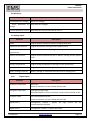

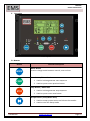
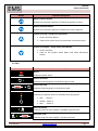
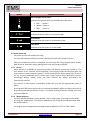

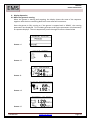

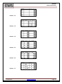
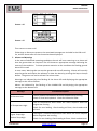
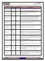

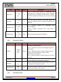
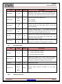
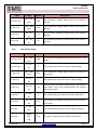

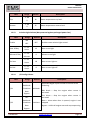

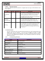
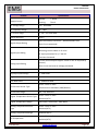

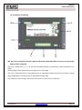
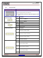
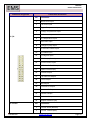
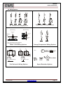
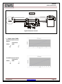
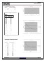
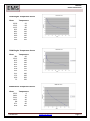
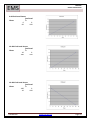
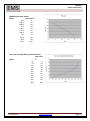


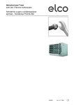


![User Manual BS 15 [ASL]](http://vs1.manualzilla.com/store/data/005675346_1-422b291500c6ff99ebe2f8b515793259-150x150.png)