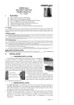
1
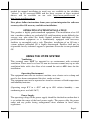
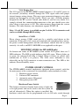
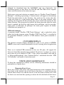
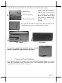
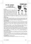
HT-4600/HT-4600E
Series
PB-4600/PB-4600E
User’s Manual
Rev. C0
FCC Notes:
This equipment generates, uses, and can radiate radio
frequency energy and, if not installed and used in accordance
with the instructions manual, may cause interference to radio
communications. It has been tested and found to comply with
limits for a Class A digital device pursuant to subpart J of Part 15 of FCC Rules, which
are designed to provide reasonable protection against interference when operated in a
commercial environment. Operation of this equipment in a residential area is likely to
cause interference in which case the user at his own expense will be required to take
whatever measures to correct the interference.
Warranty Limits:
Warranty terminates automatically when any person other than the authorized
technicians opens the machine. The user should consult his/her dealer for the problem
happened. Warranty voids if the user does not follow the instructions in application of
this merchandise. The manufacturer is by no means responsible for any damage or
hazard caused by improper application.
About This Manual:
Posiflex has made every effort for the accuracy of the content in this manual. However,
Posiflex will assume no liability for any technical inaccuracies or editorial or other
errors or omissions contained herein, nor for direct, indirect, incidental, consequential
or otherwise damages, including without limitation loss of data or profits, resulting
from the furnishing, performance, or use of this material.
This information is provided “as is” and Posiflex Technology, Inc. expressly disclaims
any warranties, expressed, implied or statutory, including without limitation implied
warranties of merchantability or fitness for particular purpose, good title and against
infringement.
The information in this manual contains only essential hardware concerns for general
user and is subject to change without notice. Posiflex reserves the right to alter product
designs, layouts or drivers without notification. The system integrator shall provide
applicative notices and arrangement for special options utilizing this product. The user
may find the most up to date information of the hardware from web sites:
http://www.posiflex.com or http://www.posiflex.com.tw
All data should be backed-up prior to the installation of any drive unit or storage
peripheral. Posiflex will not be responsible for any loss of data resulting from the use,
disuse or misuse of this or any other Posiflex product.
All rights are strictly reserved. No part of this documentation may be reproduced,
stored in a retrieval system, or transmitted in any form or by any means, electronic,
mechanical, photocopying, or otherwise, without prior express written consent from
Posiflex Technology Inc. the publisher of this documentation.
© Copyright Posiflex Technology Inc. 2011
All brand and product names and trademarks are the property of their respective holders.
P/N: 15410900040
Page 1
ALERT TO OUR HONORABLE CUSTOMERS:
Please always read thoroughly all the instructions and documents
delivered with the product before you do anything about it. Don’t
take any premature action before you have a full understanding of
the consequences.
DAILY MAINTENANCE GUIDE
For regular cleaning of the HT/PB-4600/E systems, please use only soft haired
brush or dry soft cloth. You may use moist soft cloth to remove stains when
necessary. Apply only proper amount of mild neutral detergent for obstinate
stains. Please note that never use Acryl dissolving solvent or Polycarbonate
dissolving solvent. You may apply ammonia-based glass cleaner only on the
screen surface.
BRIEF INTRODUCTION
THE USER’S MANUAL
The purpose of this manual is to guide the user in the initial installation and
general use of the Posiflex HT/PB-4600/E series of POS terminals. It does not
explain any application software that may be supplied with it.
We intend to provide our customers with all technology advantages available
by evolving the product design to incorporate appropriate changes and
improvements. So some detail differences may exist between this manual and
the equipment supplied.
For more detailed or technical information please refer to the CD-ROM disc
associated or consult our authorized dealers or visit our web site:
http://www.posiflex.com.tw/ or http://www.posiflex.com/
THE PRODUCT
The Posiflex range of HT/PB-4600/E terminals have been designed and
manufactured to meet the high end demand on POS systems. It incorporates all
the advances of PC technology within a rugged housing designed for use in a
hostile retail environment. By providing an integrated design, it has retained
many of the secure features of a traditional ECR and has avoided the wiring
“spaghetti” associated with more traditional PC solutions. This Open Standard
Architecture ensures that this terminal can use the PC application software and
Page 2
development tools that are now inexpensively available and abundant.
For the HT-4600/E series terminal is powered by most up to date CPU and
provides a color TFT LCD screen with a resistive type touch control panel on
sturdy and easily adjustable structure on top of the main unit. HT/PB-4600/E
series may be used as a self-content unit or as one of several terminals in a
network system controlled by a “back office” computer through the integrated
network interface. Versatile options besides the basic model selection can
apply to it as well. While PB-4600/E is same as HT-4600/E but without LCD
display.
THE STANDARD FEATURES
CPU: Intel Penryn 575 2.0G+
HDD: 80 GB or above.
RAM: DIMM socket x 2, DDR-2 667/800MHz, Max 4GB for HT/PB4600; SO-DIMM socket x 2, DDR3, Max 8GB for HT/PB-4600E
Data storage device: SATA HDD 2.5” or SSD HDD, support 2nd HDD
for HT/PB-4600E
Touch control functions: left/right button, double click, drag & draw
Ethernet Networking: One LAN port Ethernet 10/100/1000 Base T
with LAN status indicators on jack (green for link, yellow for data
transmission)
Serial Ports: There are 4 serial ports in a HT/PB-4600/E system with
+5V (through BIOS setting) or +12V (by jumper setting) power on
COM2/3 and it is default as no power at delivery.
Parallel Port: Each HT/PB-4600/E system is equipped with a parallel
port that supports SPP/EPP/ECP.
VGA Port: There is a VGA connector for connection of external
monitor with + 12 V DC power supply included. It is default as no
power at delivery.
USB Ports: The HT/PB-4600/E series is equipped with 6 USB type A
connectors for connection of USB (Universal Serial Bus) devices.
PS/2 KB Port: 1 PS/2 KB port
PS/2 Mouse Port: 1 mouse port
Audio Port: 1 Mic. in / audio line out port
CR Port: Capable of controlling 2 cash drawers max.
PCI Slot: 1 PCI extension slot.
Modem Ring-Up, LAN Or Alarm Wake-Up: The HT/PB-4600/E
series can be turned on automatically upon an incoming COM port
Modem call or LAN status or data packet received on LAN or a preset
time/day/week/month.
Page 3
Power supply control of COM2/3 and VGA port can be set up
through BIOS or jumper control.
THE OPTIONAL ITEMS
Note: These items below must be installed by the qualified technician.
Attempt to apply them by end users is either too difficult or is likely to cause
damages. Italic items below are stand alone peripheral devices.
a)
b)
c)
d)
e)
f)
g)
h)
Data Storage: SSD kit (It can’t coexist with HDD)
Wireless LAN Adaptor(Optional): USB interface, IEEE 802.11b/g
Preload OS: Win XP Pro, WEPOS, POSReady or Linux.
Support CRT2 through internal interface.
Optional RAID 1 Function for data security.
Two VGA ports for PB-4600/E: One for main Display and another
one for second display.
Internal speaker(This must installed prior to delivery from factory)
+24V power supply for printer.
SYSTEM BOX CONTENTS
When you receive the system box you will find it contains several items:
HT-4600/E system unit with the 12.1” LCD panel integrated on top or
PB-4600/E system unit.
User’s manual.
Recovery DVD for preloaded OS or Posiflex Product Information
DVD for driver utilities without OS.
Optional components installed to system unit as ordered.
Power adaptor and power cord.
PCI Extension slot.
INSTALLATION GUIDES
IMPORTANT
Please do not connect the power adaptor or turn on the main unit until you
have fully read the installation guides and followed the instructions!!!
TECHNICAL ENHANCEMENTS
Applicable technical enhancements in HT/PB-4600/E series include serial
COM port power supply settings, VGA port power supply setting and DRAM
upgrades. All these technical enhancement operations require purchase of
applicable Technical Manual from Posiflex or consultation from Posiflex
authorized dealers and should be handled only by a qualified technician.
Page 4
MAIN CONNECTION AREA
The HT/PB-4600/E series is constructed for very easy maintenance. Press
inward both plastic buttons at lower rear corners on both sides of the system
unit (circled in right picture) to release the lower part of back cable cover.
Please note that there are 2 plastic hooks on top cover holding the back cable
cover as marked on upper part of the picture. Carefully release the back cable
cover from the hooks to show the main connection area.
Carelessly pressing on these 2 springs could cause damages. The user shall
be responsible for such kind of damage. For the HT-4600/E system even the
maintenance technician must always put a piece of clean flat foam of sufficient
size in front of the system unit before pressing these 2 springs. The LCD and
touch panel may flip forward by gravity and get or cause damage by hitting
anything in front of the system
unit. For the PB-4600/E system
the maintenance technician must Push This Button
always pay attention to always and also The One
on The Other
disconnect all power and cable
Side to Open
connections before pressing the 2 Cable Cover
springs and not to cause any
damage either in the top cover
opening operation after pressing
the 2 springs or by leaving or
spilling any improper materials
inside after the opening operation.
Note: Please DO NOT press the 2 springs on the metal walls as cross
marked in the picture.
WIRELESS LAN (OPTION)
When the wireless LAN option is ordered with the HT/PB-4600/E system, this
option is already installed in the delivery inside the back cable cover with its
cable connected to one of the USB port. This cable must be disconnected
first if installed whenever the back cable cover is opened for any operation.
PCI EXTENSION CARD
The PCI extension card is not pre installed; therefore, it is a possibility to add a
PCI extension card. However, the whole operation will involve cautiously
accessing the interior of the system, replacing the slot window metal plate,
applying the card.
Page 5
LCD DISPLAY (for HT-4600/E only)
Push down the round plastic button at rear of the display base as circled in
right picture to adjust the display up and down. Release the button when done
will lock the panel firmly for application.
Pushing the rectangular shape plastic
Push inward to
button to its right toward the base center
turn left-right
allows user to adjust the display
horizontally for best view angle.
Push down to
turn up-down
10” 2ND DISPLAY (OPTION)
When the HT-4600/E series is ordered with the 2nd display
monitor LM-2010 or when the LM-2010 is ordered for
PB-4600/E to work as the primary monitor, the monitor
will be delivered in separate package from the system unit.
Please follow the Installation Guide in package of the
option. Then please open the system unit and set the
+12V DC supply in the VGA connector under technical
guidance from your distributor.
CUSTOMER DISPLAY (OPTION)
For HT/PB-4600/E series, Posiflex provides customer
pole displays for terminal integration such as PD2601/2601U and PD-307/307U. Please follow the
Installation Guide in package of the options. The
customer display will occupy one USB or COM port in
the connection area. Consult your distributor for technical
support on setting up the +5V DC or +12V DC supply to
the COM port used if the customer display is of the serial
interface type.
SIDE MOUNT UPGRADE KIT (SD-300 Option for HT series)
When a side-mount upgrade kit option SD300 is ordered with the HT-4600/E system,
this option is already installed in the
delivery. No matter the kit it contains MSR
only, finger print sensor only or both options, the connection to
the HT-4600/E system is one USB cable inserted to the extended
USB port at top right edge of the system unit as circled in the
upper picture at right.
Page 6
After removing the plastic cover by pushing it side
way, the extended USB port can be found as marked
in the lower picture at right.
The USB cable from the optional side mount upgrade
kit SD-300 should be inserted in the cable hook on back of LCD panel as
circled in left picture.
AUDIO PORT
The audio output port must be connected to either the earphone or a pair of
speakers with booster or amplifier if used.
Power Adaptor
The operating voltage range of the power adaptor should cover the local power
supply for proper operation. The power cable, the power outlet and any power
fusing arrangements must conform to local safety regulations.
Note 1: Please do not any connect / disconnect action when system is still
powered on. Please always keep the external power adaptor in a
free air circulation.
Note 2: For +24V power kit PA-4600, it needs to change power adaptor as
it attached.
OPERATING SYSTEM RECOVERY
The operating system exists in the HDD which in the system unit. Once the
software system on HDD damaged, it is possible to restore the operating
system onto a physically intact HDD with use of the Recovery CD or DVD
that comes with the preloaded operating system. Please follow the instruction
from your system integrator for system / software restoration. Following
instructions is for operating system recovery only if your system integrator
does not advise otherwise.
For the HT/PB-4600/E system preloaded with Windows system on HDD,
Posiflex provides recovery DVD delivered with the hybrid terminal for the
preloaded operating system. The System Integrator shall take care of software
restoration after OS recovered. Use a USB interface external CDROM or DVD
COMBO drive for such action.
Please use the recovery DVD in rescue operation only. Using it otherwise
may wipe out whatever stored in the HDD! All upgrade devices drivers
Page 7
needed for manual installation in usual way are available in the subfolder
“\drivers” in OS recovered HDD and the latest versions of these required
drivers will be available on our web: http://www.posiflex.com or
http://www.posiflex.com.tw.
Now please follow instructions from your system integrator for software
recovery after OS recovery and driver installation.
OPERATING SYSTEM INSTALLATION
This product is highly professionalized equipment. The installation of an OS
into a machine without any preloaded OS could constitute major difficulty for
average user who either has barely limited technical knowledge of this
professionalized equipment or is insufficiently equipped with necessary
facilities to accomplish such a task. Therefore, installation of an OS into a
system without preloaded OS is highly discouraged. Posiflex shall not be
responsible for any technical support to questions arisen due to non-preloaded
OS.
USING THE HT/PB SYSTEM
Ventilation
This terminal must NOT be operated in an environment with restricted
ventilation. There must be at least 25 mm air clearance around any top or side
ventilation holes with a free flow of air around the unit at ALL times for the
installation.
Operating Environment
The equipment must not site in direct sunshine, near a heater or in a damp and
must be free from contaminants like dust, smoke or fume.
The equipment must not be operated or stored in extremes of both temperature
and humidity/moisture.
(Operating range 0°C to + 40°C and up to 80% relative humidity – non
condensing max. wet bulb 26°C)
Power Supply
The operating voltage of the power supply should be checked to confirm that it
is set within the range of the local power supply. The power cable, the power
outlet and any power fusing arrangements must conform to local safety
regulations.
Page 8
VGA Display Port
The VGA port in the HT/PB-4600/E terminal supports a 12 volt DC power to
the external (secondary) monitor through the VGA signal cable after proper
internal jumper setting change. This may cause permanent damage to any other
monitor not designed to use this facility. Please use only a Posiflex monitor
designed for the HT system. Consult your dealer if you have any doubt. It is
strongly advised that connection/disconnection to this port should never take
place when system power is ON. The video memory shares from the system
memory. The video memory size adjustment support DVMT 5.0.
Note: 12 volt DC power is available on pin 9 of the VGA connector and
can be available through BIOS setting.
Serial Port – COM1
Please always occupy COM1 serial port by a suitable serial device or this
terminator. If this port is left vacant or connected with something like a mouse,
the power switch management and the cash drawer control may fail to work
correctly. As well as an RS232 MODEM is not applicable to this port.
LED INDICATORS (for HT-4600/E only)
On bottom rim center of HT-4600/E system cashier LCD panel, there are 2
LED indicators. The LED at right indicates the LAN status. When it lights up
in green, the onboard LAN chip is linked. When it flashes in yellow, data
transmission in LAN is in process. The LAN status indication is also
observable on the LAN connector in main connection area. The LED at left
indicates Power/Stand-By status.
POWER ON/OFF CONTROL
The HT/PB-4600/E terminal implements electronic power control, such that
the main power to the system may be controlled by many methods as below:
1. Hardware power switch
2. Software OFF command
3. Automatic power ON control
4. Emergency power OFF
Hardware Power Switch
This button is located at bottom front corner of right side
as in right picture and can be used to turn the system on
and off alternatively. When this option is installed, this
hardware switch can also be programmed to be an ON only switch through
Page 9
software command so that when this switch is accidentally pressed during
system turned on, the system just remains on and unaffected.
Software Off Command
The system may also be shut down under software control. Please just follow
the arrangement by your system integrator for this capability.
Automatic Power On Control
The system may also turn on according to some preset conditions such as
Modem Ring Up and Alarm Clock Wake Up or LAN Wake Up. To utilize
Modem Ring Up or Alarm Clock Wake Up function, please enter the CMOS
setup by pressing “Del” key at system boot up, choose for “PM Wake Up
Events” in “Power Management Setup” and make the “Ring Power up
Control” enabled for Modem Ring Up or select the “Power Up by Alarm” for
Alarm Clock Wake Up. Save the configuration and exit the CMOS setup
program. The Preset Power on Control will then be ready after a normal power
off. For LAN wakeup, an operating caller system connected through LAN to
the system is required. It also requires a qualified networking technician to
check the LAN chip ID of the HT/PB-4600/E system for the caller system to
wake it up.
When the HT/PB-4600/E system is turned off after a successful boot up, the
preset automatic power on functions will keep monitoring for the preset
conditions and turn on the system when the preset conditions are met.
Please note that if the HT/PB-4600/E system is improperly turned off before a
complete boot up procedure, the above preset power on control functions will
be disabled until next turning off after a complete boot up.
Emergency Power Off
In case of serious system halt due to any reason, the system could fail to be
powered off through normal means. Press and hold the Power ON/OFF Switch
for Emergency Power Off. Release the switch after the system powered off. It
will take about 10 seconds.
MAIN LCD TOUCH MONITOR (for HT-4600/E only)
Mechanical Adjustments
The 12.1” LCD color display is integrated on display platform to give the
operator the clearest view. The inclined angle of the display may be adjusted
from 15° to 50° and rotated from straight forward to 16° to the left.
Page 10
Display Controls
On lower left edge of back of the LCD panel there is
a plastic wheel knob as circled in the picture at right.
Please turn this knob up or down changes the
brightness of screen display accordingly.
Display Utility Driver
The end user of the HT-4600/E terminals is not
supposed to install the utility drivers personally. If an optional preloaded OS is
ordered, the required driver will be already installed in the preloaded OS.
However, the driver will always be available over our web site:
http://www.posiflex.com
Touch Function
Mouse emulation
The touch panel in HT-4600/E system works like a standard mouse within the
(primary) screen display area when its driver is properly installed. However, if
the system is running under safe mode due to a previous improper shutdown or
for any other reason, most drivers are disabled in this mode and the touch
panel calibration may not coincide with the mouse pointer or even completely
out of work. It is recommended to use an USB mouse or USB keyboard in
safe mode.
All the below mentioned mouse emulation functions in the primary display
area can be manipulated through relevant software. The system can give a beep
when the touch panel is touched and can respond as if the left button of a
mouse is clicked at the point touched. If the point touched is dragged across
the screen surface, it can respond as if it is using the mouse drag and drop
feature. If the point is touched, released and touched within a short time
interval, it will simulate double-clicking left button of the mouse.
Touch terminal manager
Before using the resistive type touch control panel, one must be aware that if
you connect any monitor to the VGA port of HT-4600/E system for extended
secondary display application, you can not apply any touch control function
for this secondary display! The operation range is limited within the primary
display area.
A program named “Posiflex Touch Terminal Manager” is installed in the
preloaded Windows system for the user to maneuver versatile features of the
touch terminal with a touch panel controller. This program can also be
Page 11
obtained by download from the POSIFLEX web site. Conversely, the
installation process of this driver for Win XP and Win 2003 Server requires
some careful attention to the notice messages.
With proper setup and selection on control items in “Posiflex Touch Terminal
Manager”, a drawing representing a 2-button mouse will appear on the desktop.
Touch the right button in this drawing. Any touch on the screen after this
action will result in a right button mouse click at the point touched. After
touching the left button in this drawing the screen touch will resume the left
button function. This program also controls the beep generated when the touch
panel is touched, the detail in right button click emulation, and also provides
touch panel re-calibration. In principal, the touch panel requires no further
calibration once properly set.
USB touch manager
A program named “Posiflex USB Touch Manager” and a right-click sticky
button tool in the program group “Posiflex USB Touch Tools” is installed in
the preloaded Windows system if a USB interface touch panel controller is
installed.
CUSTOMER DISPLAY
The optional customer display mounted on a pole at rear corner of HT/PB4600/E system can be turned horizontally for best viewing effect in application.
USB
There are 6 standard USB connectors in the rear I/O plate. All support the
Universal Serial Bus Specification standard 2.0 and also 1.1. If for any reason
these ports has to be limited as USB 1.1 only, please enter BIOS setup and go
to “Integrated Peripherals” then “Onboard Device” and disable the item “USB
2.0 Controller” and enable it back afterwards.
VENTILATION MAINTENANCE
To keep this equipment in orderly service, following maintenance should be
performed on a regular basis.
Removing Front Cover
Please first remove any power and signal connection to this equipment. Please
then check at the bottom side of the chassis that there is a gap between the
bottom side of front cover and the chassis at the left corner of front cover. Pull
the front cover out from this opening to release the left side hook of front cover
Page 12
from the chassis as indicated by the hollow arrow in the right picture.
Front Cover
Release Opening
Chassis Bottom View
Please then pull the bottom
side of front cover forward
to release the bottom
hooks of front cover from
the chassis as indicated by
hollow arrow in left
picture.
Now pull the left side of front cover down a little to free
it from the main cover as in the pictures below.
HT-4600/E
PB-4600/E
It may be required to push the power switch
down to completely remove the front cover.
Power Switch
Cleaning for Front Ventilation
Use vacuum cleaner to remove any dust or threads accumulation away from
both the ventilation holes on front cover and ventilation grids on chassis
exposed after removal of the front cover.
Page 13
HT-4600/E
PB-4600/E
Front Ventilation Grids on Chassis
Ventilation Holes on Front Cover
Replacing Front Cover
Follow the opposite procedure as removing the front cover to replace the front
cover in position. Please make sure the all hooks on front cover is well
positioned into chassis. Please remember to check that the power switch is at
“Off” position before power and signal connection.
Accessing Side Ventilation Grids
The operation to further clean the side ventilation grids requires much more
highly technical maneuver. Therefore careful attentions must be taken
throughout the further cleaning operations below. When the main unit is
opened, there must be no liquid spill, no electro-conductive material, no
electric charged device come into the area of the main unit. Please also note
that not to touch any component or cable inside.
Please first disconnect every cable from
the main unit and for the HT-4600/E
turn the LCD panel to straight up
position. Prepare enough space in front
of the HT/PB-4600/E system and lay a Push The
piece of clean soft clothes of Spring
appropriate size there to prevent damage. Buttons on
Both Sides
With the back cable cover opened, push and Raise The
in the circled spring button in the right Rear Part of
picture on both sides of chassis and Top Cover
raise the rear edge of the top cover.
Apply some mild maneuver if there is
already a pole display mounted.
Page 14
Cleaning for Side Ventilation
Use vacuum cleaner to remove any dust or threads accumulation away from
outsides of both ventilation grids on chassis exposed after removal of the front
cover as in pictures below and close back the top cover when done.
Side
Ventilation
Grids on
Chassis
警告使用者
T31454
這是甲類的資訊產品,在居住的環
境中使用時,可能會造成射頻干
擾,在這種情況下,使用者會被要
求採取某些適當的對策。
Page 15