1
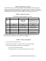
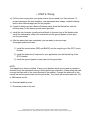
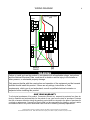
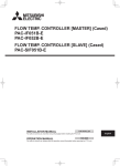
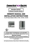
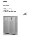
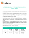
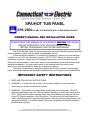
SPA/HOT TUB PANEL
SPA-260b 60 AMP GFCI BREAKER WITH 15 AMP BRANCH CIRCUIT
OWNER’S MANUAL AND INSTALLATION GUIDE
PLEASE READ THIS MANUAL IN ITS ENTIRETY BEFORE INSTALLING
AND/OR OPERATING YOUR SPA DISCONNECT PANEL.
RETAIN THIS MANUAL FOR FUTURE REFERENCE.
The SPA-260b Spa Panel you have purchased is the finest available anywhere and with
proper installation, will provide you years of dependable service.
Follow instructions carefully. For questions or assistance, contact your local electrical
contractor or our Toll-Free Assistance number 1-800-730-2557. Before you start on a wiring
installation or addition, contact your local building inspector for current local and National
Electrical Code information. Local codes vary but are adopted and enforced to promote safe
electrical installations. You may need a permit to do electrical work and codes could
require your work be checked for safety by an electrical inspector.
This panel is engineered to meet the requirements of spas, fountains, swimming/lap
pools, submersible devices and therapeutic equipment but is not limited to these applications.
IMPORTANT SAFETY INSTRUCTIONS
1. READ AND FOLLOW ALL INSTRUCTIONS.
2. WARNING - To reduce the risk of injury, do not permit children to use this product,
unless they are closely supervised at all times.
3. WARNING - This product is provided with a ground-fault circuit interrupter. The GFCI
must be tested before each use. With the product operating, push the test button on the
GFCI. The product should not operate. Now, reset the breaker by moving the trip lever
to the OFF position and then to the ON position. The product should now operate normally. If the product fails to operate in this manner, there is a ground current flowing, indicating the possibility of an electric shock. Disconnect the power until the fault had been
identified and corrected.
Corporate Office: 100 West 11th Street, Anderson, IN 46016 Ph. (800) 730-2557, Fax (765) 608-5036
West Coast Distribution Center: 5508-128th Street East, Puyallup, WA 98373 Ph. (800) 472-3819, Fax (253) 471-9540
2
STEP 1: Determine Location
The SPA-260b panel is to be located between 5 feet (minimum) and 50 feet (maximum)
away from your spa (or other equipment). The panel is required to be within “line-of-sight” of
the equipment that it is servicing. This product can be mounted on a wall or stand alone on a
bracketed post. This product is housed in a NEMA Type 3R (rainproof) enclosure.
STEP 2: Select Wire Size
The following are typical amperages / wire sizes :
60OC (140OF)
75OC (167OF)
90OC (194OF)
SIZE
AWG
Types TW, UF
Types RHW,
THHW, THW,
THWN, XHHW,
USE, ZW
Types TBS, SA,
SIS,FEP,FEPB, MI, RHH,
RHW-2, THHN, THHW, THW2, THWN-2, USE-2, XHH,
XHHW, XHHW-2, ZW-2
14
20A CU
20A CU
25A CU
12
25A CU or 20A AL
25A CU or 20A AL
30A CU or 25A AL
10
30A CU or 25A AL
35A CU or 30A AL
40A CU or 35A AL
8
40A CU or 30A AL
50A CU or 40A AL
55A CU or 45A AL
6
55A CU or 40A AL
65A CU or 50A AL
75A CU or 60A AL
4
70A CU or 55A AL
85A CU or 65A AL
95A CU or 75A AL
Note: Four conductors (hot, hot, neutral, ground) are required to properly power this unit.
Check codes to see which wire can be used in your application.
STEP 3: Wiring Preparation
a) Turn off the main electrical service.
b) Remove the two interior cover screws. Remove cover and set aside.
c) Remove the appropriate knockout(s) for your application.
1) Drive the center knockout inward.
2) Alternately drive in or pry up the knockout rings, one at a time.
Corporate Office: 100 West 11th Street, Anderson, IN 46016 Ph. (800) 730-2557, Fax (765) 608-5036
West Coast Distribution Center: 5508-128th Street East, Puyallup, WA 98373 Ph. (800) 472-3819, Fax (253) 471-9540
3
1.
STEP 4: Wiring
a) Pull the wires coming from your power source (house panel) into the enclosure. To
prevent damage to the wire insulation, use appropriate wire clamps, conduit bushings
and/or other methods approved for this purpose.
b) If panel is being used as a Service Entrance panel, bond the Neutral bar, with the
bonding strap, to the chassis ground screw provided.
c) Install the two hot wires (usually red and black) to the main lugs of the breaker stab.
Install the neutral wire (white) into neutral bar and the ground (green or bare wire)
into the ground bar.
d) After the above has been completed, you are ready to wire your spa.
Using appropriate sized wire:
1) Install the two hot wires (RED and BLACK) into the output lugs of the GFCI circuit
breaker.
2) Install the white wire (if required for your application) into the Neutral lug of the
GFCI breaker
3) Install the ground (green or bare) wire into the ground bar.
NOTE:
Your panel has a factory installed 15 amp circuit breaker which can be used as needed or
desired. Route the appropriate wiring to this load through a knockout. When wiring this load,
connect the black wire to the output terminal of the breaker. Connect the white wire to the
neutral bar and the ground wire into the ground bar. Your panel will accommodate two 15A
or 20A branch circuits.
e) Reinstall deadfront cover
f) Reconnect power to the unit
Corporate Office: 100 West 11th Street, Anderson, IN 46016 Ph. (800) 730-2557, Fax (765) 608-5036
West Coast Distribution Center: 5508-128th Street East, Puyallup, WA 98373 Ph. (800) 472-3819, Fax (253) 471-9540
WIRING DIAGRAM
WARNING
Failure to install and use the product in accordance with all applicable ratings, instructions
and the National Electrical Code, could result in death or serious injury to the installer or
other persons, or substantial property damage.
Only persons familiar with the construction and operation of the equipment and the hazards
involved should install this product. If there are any ratings, instructions or Code
requirements, which you do not understand, consult a qualified electrical contractor or
inspector before installing this product.
ONE YEAR WARRANTY
To all original purchasers of its product, Connecticut Electric Inc. warrants its products free from defects in materials and workmanship for the period of one year from the date of purchase. Products
that fail or become defective during the warranty period shall be returned to the place of purchase for
a refund or replacement. Connecticut Electric shall not be responsible for shipping, removal, and/or
reinstallation labor or any other associated costs incurred in obtaining warranty replacement.
Corporate Office: 100 West 11th Street, Anderson, IN 46016 Ph. (800) 730-2557, Fax (765) 608-5036
West Coast Distribution Center: 5508-128th Street East, Puyallup, WA 98373 Ph. (800) 472-3819, Fax (253) 471-9540
4