1
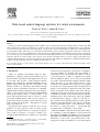
Advances in Engineering Software 33 (2002) 155±168 www.elsevier.com/locate/advengsoft Rule-based natural-language interface for virtual environments Tamer M. Wasfy a, Ahmed K. Noor b,* a b Advanced Science and Automation Corporation, Hampton, VA, USA Center for Advanced Engineering Environments, Old Dominion University, Mail Stop 201, NASA Langley Research Center, Hampton, VA 23681, USA Accepted 11 December 2001 Abstract A hierarchical rule-based natural-language interface (NLI) for object-oriented virtual environment (VE) toolkits is described. The NLI allows modifying the properties of existing objects, as well as creating new objects in the VE using near-natural language speech. The rules are organized in a tree hierarchy with each rule branching to a `group of rules'. Each tree-branch forms a possible user's command. Each rule generates global variables, which can be accessed by rules down the branch in order to formulate an appropriate action for the command. The action consists of a set of script commands that are sent to the VE. Also, the NLI maintains a state that allows it to respond to a command in the context of the previous command that the user issued. The hierarchical NLI exploits the object-oriented data structure of the VE toolkit by using three main levels of rules, namely, object, property, and action rules. The NLI can run on a remote computer and is linked to the computer running the VE via a network socket connection. The application of the NLI to the visualization of computational ¯uid dynamics results in a virtual wind tunnel is presented. Published by Elsevier Science Ltd. Keywords: Natural language recognition; Expert systems; Arti®cial intelligence; Voice recognition; Virtual environments; Virtual reality; Object-oriented software; Visual simulation 1. Introduction Virtual (or synthetic) environments (VEs) are threedimensional, computer generated environments that can be interactively experienced and manipulated by the user in real time. VEs provide a natural interface between humans and computers by arti®cially mimicking the way humans interact with their physical environment. A VE includes facilities for interfacing with humans through output of sensory information and input of commands. Output facilities include an immersive stereoscopic display, and two or more speakers. Input facilities include hand-held 3D navigation devices, such as a wand, joystick, or 3D mouse; 2D navigation devices, such as a mouse or a touch pad; haptic feedback devices, such as gloves; devices for position and orientation tracking of parts of the user's body (such as the head and hands); a microphone for speech input; and a keyboard. An important user interface mode that has not been utilized to its full potential in VEs is natural speech. Currently, most speech interfaces to computers in general, and to VEs in particular, are based on simple voice commands. The main limitation of simple voice commands * Corresponding author. Tel.: 11-757-864-1978; fax: 11-757-864-8089. E-mail address: [email protected] (A.K. Noor). 0965-9978/02/$ - see front matter Published by Elsevier Science Ltd. PII: S 0965-997 8(02)00004-2 is that for practical applications, the user has to remember a very large number of commands. The large number of commands increases the learning time, which is contrary to the main purpose of VEsÐto eliminate the learning time by making the VE as close to the real environment as possible. A rule-based natural-language interface (NLI) allows the users to use their natural speech to issue commands to the VE. Each rule consists of a set of required words and a set of ignored words, with each required word having a set of synonyms or alternative words. Any combination of synonyms of the required words, along with any combination of the ignored words, can be used to issue the command. For example, for the command `show model', the required words are `show' and `model'. `Show' has a number of synonyms such as `display', `switch on', and `turn on'. Also, `model' has the following alternative words `airplane' and `plane'. The ignored words are `the' and `me'. So the user can say `show me the airplane', `turn on the model', `switch the model on', `display the plane',¼, and the NLI will recognize all those commands as `show model'. Rule-based NLIs for VEs have been developed in Refs. [1±7]. In Ref. [1], a rule-based NLI for a web-browser based VE, which uses HTML and VRML was developed. This NLI handles commands in the form of imperative sentences, which have an action verb, a prepositional phrase, and a noun phrase. Nouns and adjectives can be detected from 156 T.M. Wasfy, A.K. Noor / Advances in Engineering Software 33 (2002) 155±168 the context of the sentence, thus allowing new knowledge to be introduced in the NLI. In Refs. [2±5], a rule-based expert system using NASA's CLIPS [6] was developed. This expert system interprets the users's multimodal input, which includes natural-language and gestures, along with the state of the VE, into commands. A command consists of an object, an actor, an action, and a direction for the action. The command is converted to script that is sent to the VE via UNIX sockets. The rule-based expert system was used to drive a virtual robot around a VE [2] and to develop a sinus surgery interface for training [3]. The system can also monitor the surgeon's progress in the surgical procedure and provide feedback. It can also provide navigational assistance and identify critical anatomical structures. In the aforementioned papers natural language processing was achieved using a limited vocabulary (100±200 words or short phrases), which can been combined to form the possible commands for the target application. In the present paper, a hierarchical rule-based NLI is presented, which can be used to control an object-oriented VE toolkit. The NLI allows creating new objects and modifying the properties of existing objects in the VE using natural language spoken or typed commands. The spoken commands are acquired using a USB microphone connected to a PC running Microsoft Windows 2000 along with Microsoft Speech API Version 5.1. As in the aforementioned references, a limited vocabulary of about 500 words and short phrases is used. The rules can be organized in a hierarchal tree by grouping rules into `rules groups'. Each rule can `connect' to a rules group. Each tree-branch forms a possible user's command, which allows generating a large number of commands from a relatively small number of rules. When a rule along a branch is activated, it generates global variables, which can be accessed by subsequent rules on the branch in order to formulate an appropriate action for the command. The action consists of a set of script commands that are sent to the VE. Also, the NLI maintains a state that allows it to respond to a command in the context of the previous command(s). The hierarchical NLI can take advantage of the object-oriented data structure of the VE by organizing the rules into three main levels, namely, object, property, and action rules. The NLI can either run on the same computer running the VE or it can run on a remote computer that is linked to the VE computer via a network socket connection. The application of the aforementioned hierarchical rulebased NLI to the visualization of computational simulation and experimental results in VEs is described. This application can be viewed as an interactive, speech-enabled interrogative visualization of the analysis results. To the authors' knowledge, this is the ®rst time that a hierarchical rule-based expert system NLI has been used to support interrogative visualization of engineering systems in immersive VEs. Speci®cally, the application chosen herein is the visualization of spatial ¯uid-¯ow ®elds around aerospace vehicles. The ¯ow ®eld was calculated using a computational ¯uid dynamics (CFD) code. The display of ¯ow ®elds around engineering systems in immersive VEs allows natural and fast exploration and visualization of the ¯ow, and its effects on the engineering system. This, in turn, can help optimize the con®guration and geometry of the system. In addition, experimental results can be superposed, subtracted, or placed next to the CFD results in the VE, in order to assess the accuracy of the CFD simulations. Also, a photo-realistic model of the engineering system can be viewed along with the natural surroundings. This provides the user with a better understanding of the model. The following visualization objects are used for interactive visualization of CFD ¯ow ®elds: ² Stream objects: lines, surface-restricted lines, ribbons, and volumes ² Colored and contoured surfaces ² Surface arrows ² Elevation surface and line graphs ² Global and local iso-surfaces ² Vortex cores ² Flow separation/reattachment surfaces and lines The NLI combined with the immersive stereoscopic display in the VE provide the user with a more natural interface in controlling the visualization of large complex datasets in which the user can say the command using near-natural speech. 2. Natural-language interface The VE hardware and toolkit used in the present study are described in Appendix A and Refs. [8±10]. The virtual wind tunnel used in the CFD application is highlighted in Appendix B. A schematic diagram of the architecture of the NLI is shown in Fig. 1. Three types of input ®les are required for the NLI. These are: ² An initialization ®le. This ®le contains the IP address and socket port number of the computer running the VE program. ² A vocabulary ®le. This ®le contains a list of single words or short phrases which are set as the vocabulary for the Microsoft Speech API. Typically this list consists of 500±1000 words/short phrases that can be used in any combination to issue all possible commands for the current VE application. Using limited vocabulary, single word/phrase recognition mode was found to be much more reliable and robust than continuous dictation speech with a large (.30,000 words) vocabulary. The accuracy rate for the single word/phrase recognition mode was above 96% as opposed to below 70% for continuous dictation. Also, this mode is not as restrictive as command and control mode, where the vocabulary consists of the set of control commands, thus restricting the user to say only programmed commands. The main restriction of this mode is that the user has to separate the T.M. Wasfy, A.K. Noor / Advances in Engineering Software 33 (2002) 155±168 157 Fig. 1. NLI architecture. words clearly during the speech by pausing for about 0.2 s between each word. The fact that the user is restricted to use about 500±1000 words/short phrases, and that s/he has to pause for 0.2 s between words means that the user's speech is not totally natural but near natural. ² Rule ®les. Each rule ®le consists of a set of rules and a set of rule groups. Each rule has a name and a set of properties. A rule group contains a list of names of the rules contained in the group. The properties of the rules and rule groups are described in Sections 2.1±2.3. The NLI generates synthesized speech messages through speakers using the Microsoft Speech API, in response to user's commands. The natural language commands can be issued by speaking through a microphone or by typing on a computer keyboard. Microsoft speech API is used to translate the user's speech into individual (vocabulary) words. The user instructs the NLI to execute the command by saying a special keyword such as `do it' or `execute after issuing the command'. The NLI interfaces with the VE program by sending script commands. The script commands can do any combination of the following: ² Changing one or more properties of the existing objects in the VE. This includes displaying text messages in the VE. The VE can contain a `TextBox' object. The script can set the `text' property of this object to the desired output message, thus displaying the message in the VE. ² Creating new objects in the VE. ² Sending data back to the NLI. This data is sent by setting the `send' property of the `Server' object to the string of data that is to be sent back to the NLI. For example, the NLI can request the value of a color property of an object, using the following script command: `server1.send object1.color'. 2.1. Rules group The rules group `Group' object allows grouping a set of rules, including other rule groups, in order to provide the ability to construct hierarchies of rules. Each group has a name and includes a list of rule names or group names, which are contained within the group. Fig. 2 shows a typical listing of a rules group. Fig. 3 shows how the rule groups are used to construct a rule tree. The root rules are placed in a special container called `START_GROUP'. 2.2. Rule A rule is an object consisting of a name and a list of properties and property values. The properties of the rule Fig. 2. Rules group. 158 T.M. Wasfy, A.K. Noor / Advances in Engineering Software 33 (2002) 155±168 Table 1 Properties of a rule Properties Words properties required Parameters Description plusScore; minusScore [`keyword1' `keyword2' ´´´] De®nes a required word along with all its possible synonyms. If the one of the `keywords' is found in the command then plusScore is added to the total score. If none of the `keywords' is found in the command, then minusScore is subtracted from the score. De®nes a set of ignored words. The ignored words do not affect the total score. This numeric value is added to the total score for each word, which is neither a required nor ignored word. This value should be negative. ignored [`keyword1' `keyword2' ´´´] scoreOther score Variable manipulation properties readNumber getVar setVar incVarPercent; incVarVal variableName variableName [script for getting the variable] variableName; variableValue variable; percentVariable decVarPercent; decVarVal variable; percentVariable incMeanPercent; incMeanVar variable1; variable2; incVariable decMeanPercen; decMeanVar variable1; variable2; decVariable incRangePercent; incRangeVal variable1; variable2; percentVariable decRangePercent; decRangeVal variable1; variable2; percentVariable Script properties script [list of script commands] Output properties speak reply `Spoken output message' `Written output message' State properties state1 state2 `state1 words' `state2 words' First state string Second state string Hierirchical properties connect ruleGroupName Name of the rules group that this rule connects to if it is satis®ed. along with descriptions of each property are given in Table 1. A rule has ®ve main types of properties: Word properties. These properties are used to calculate a satisfaction score for the rule. If that score is greater than Reads a real number from the input command and stores it. De®nes a variable and receives its value from the VE. De®nes a variable and sets its value. Increases a real number variable value by either a desired percentage or by a desired value. Decreases a real number variable value by either a desired percentage or by a desired value. Increases the mean value of two real numbers variables by either a desired percentage or by a desired value. Decreases the mean value of two real numbers variables by either a desired percentage or by a desired value. Increases the range value of two real numbers variables by either a desired percentage or by a desired value. Decreases the range value of two real numbers variables by either a desired percentage or by a desired value. Contains the script that is to be sent to the VE when the rule is triggered. a certain threshold, then the rule is triggered. A command consists of a number of words. Each command word is checked against a set of `required' and `ignored' words. The total score for a rule is equal to the summation of the plusScore for the required that are found, the minusScore Fig. 3. Rules tree. Each box is a rules group. T.M. Wasfy, A.K. Noor / Advances in Engineering Software 33 (2002) 155±168 159 Fig. 4. Examples of standalone (non-hierarchical) rules. for the required that are not found, and the scoreOther for the other words that are neither required words nor ignored words. Note that if the plusScore for the required words is negative, this means that if those words are found then the score is reduced. Variable manipulation properties. These properties are used to create and set the values of variables; send them to the VE; and receive them from the VE. The values of these variables are stored during the hierarchical evaluation of a command so that they can be accessed by subsequent rules. Any script can contain the names of these variables. Before the script is sent to the VE, the names of the variables are substituted by their values. Script property. Contains the script that is to be sent to the VE upon triggering the rule. Output properties. The speak and reply properties output spoken messages and on-screen message, respectively. State properties. States (state1 and state2). After a rule is triggered it leaves the NLI in the state speci®ed by the state1 and state2 properties, which provide a context for the next command. The user does not have to repeat that context. For example, the user can ®rst say `show streamline probe'. This triggers the rule for setting the visible property for the streamline probe to ON. The rule also sets the state of the NLI to `streamline probe'. Next the user can say `show arrows'. The NLI ®rst tries to execute this command without the state and it will not be able to ®nd a corresponding rule. Next it will add the state to the command, thus triggering the rule `show streamline probe arrows'. Through the aforementioned facilities, the NLI behaves as a human-assistant by relating the current command with the previous command. Some examples of standalone (non-hierarchical) rules are shown in Fig. 4. Fig. 4a shows a rule for hiding the object `Cont_Tunnel'. Fig. 4b shows a rule for setting the value of the property `minShade' for the object `surfShade_Cont' to the value requested by the user. Fig. 4c shows a rule for increasing the range between the properties `minShade' and `maxShade' of the object `surfShade_Cont' by a percentage requested by the user. Fig. 4d shows the a rule for returning to the user the value of the properties `minShade' and `maxShade' for the object `surfShade_Cont'. 2.3. Hierarchical rules The hierarchical rules for a VE can divided be into three types of rules, namely, object, property, and action rules (see Fig. 5). An object rule re¯ects the structure of the actual VE object. It `connects' to a rules group containing a set of rules that correspond to the properties of the VE object. For example, Fig. 6 shows the rule for the object `model'. The 160 T.M. Wasfy, A.K. Noor / Advances in Engineering Software 33 (2002) 155±168 Fig. 5. Rules hierarchy in the VE. rule is triggered whenever there is the word `model' in the user's command. This rule ®rst sets the values of two variables `objName_out' and `objName_scr' which are used by the subsequent rules on the branch. Then, the rule connects to a set of property rules and action rules which correspond to the properties of the VE object `Cont_Model'. Note that `Cont_Model' is a VE container object that contains other objects. Setting a property value for that container, sets the corresponding property values for all children objects. For example, the container object does not have a property `transparency', but the `Cont_Model' container includes a `Material' object which has that property. Therefore, changing the transparency property for that container changes the transparency property for that material. A property rule connects to a group of actions rules, which contains the actions that can be performed on the property. For example, Fig. 7 shows the rule for the property `transparency' which is a real number between 0 and 1. As in the case of the object rule, this rule ®rst sets the values of two variables `propName_out' and `propName_scr' which are used by subsequent rules on the branch. The rule connects to the `actions_real1' group, which contains a set of actions that can be performed on real number properties. These include: ² ² ² ² ² ² Setting the property to a desired value. Increasing the property by a desired percentage. Decreasing the property by a desired percentage. Increasing the property by a desired value. Decreasing the property by a desired value. Inquiring about the value of the property. Fig. 8 shows a typical action rule for setting a real variable to a desired value. The values of the variables `objName_scr', `propName_scr', `objName_out', and `propName_out' are obtained from the previous rules (namely, an object and a property rule) which where triggered to reach this action rule. Fig. 6. A typical object rule (model object). T.M. Wasfy, A.K. Noor / Advances in Engineering Software 33 (2002) 155±168 161 Table 2 Objects used in the X34 CFD visualization VE and the number of rules associated with each object Objects Fig. 7. A typical property rule (transparency property). 3. Application of the NLI to visualization of CFD results The NLI is applied to the exploration and visualization of the steady-state CFD results around an X34 model inside NASA Langley's 31 Inch Mach 10 wind tunnel [8]. The CFD results presented are for the reentry of the X34 vehicle in the Earth's atmosphere at Mach 7 and 248 angle of attack. The visualization objects in the VE can be divided into six main categories (see Table 2 and Appendix B): X34 model. This includes the surface of the model. Other models. These include the wind tunnel, the experiment model, and the color bar. Stream objects. These include streamlines, stream ribbons, stream volumes, and surface-restricted streamlines. Iso-surfaces. These include iso-surfaces for various scalar response quantities, namely, pressure, density, velocity magnitude, Mach number, and vorticity magnitude. Global ¯ow features. These include vortex cores and separation and reattachment lines and surfaces. Probes. These include streamline, stream ribbon, and colored cutting planes surface probes. X34 model Left X34 model Right X34 model Wind tunnel Experiment Streamlines Surface-restricted streamlines Streamline ribbons Stream volumes Pressure iso-surface Mass density iso-surface Velocity magnitude iso-surface Vorticity iso-surface Temperature iso-surface Mach number iso-surface Vortex cores Separation surfaces Attachment surfaces Separation lines Attachment lines Streamline probe Stream-ribbon probe Surface probe Total Number of rules 120 2 2 4 56 144 144 144 156 74 74 74 74 74 74 36 68 68 62 62 144 144 144 1944 the VE include: X34 model ± Show or hide a model the X34 model by saying `show model' or `hide model' (see Fig. 10a). Each object has a corresponding rule, which connects to the property rules of that object (see Fig. 6). Each property rule connects to group of action rules (see Figs. 7 and 8). A total of 128 rules, of which 27 are objects rules (see Fig. 9), 69 are property rules, and 32 are action rules, are used in this example. The total number of possible commands (tree branches) generated by using the hierarchical rules was 1944 (see Table 2). For each category of visualization objects, some of the natural-language voice commands that the user can issue in Fig. 8. A typical action rule (set action). Fig. 9. Main object rules for the X34 CFD visualization VE. 162 T.M. Wasfy, A.K. Noor / Advances in Engineering Software 33 (2002) 155±168 Fig. 10. X34 model: (a) colored using light, and (b) colored using a response quantity (pressure). ± Change the color or transparency of the model, for example, by saying `set transparency at point ®ve'. This makes the model semi-transparent. Note that the user does not have to repeat the word `model' if the last command issued involved the X34 model because this word is in the current state. ± Color the model using various scalar response quantities such as pressure, temperature, mass density, or vorticity magnitude. For example, the user can say `Color model using pressure' (see Fig. 10b). Other models ± Display other objects such as the wind tunnel (Fig. 11a) by saying `display wind tunnel'. The user can open the wind tunnel door by saying `open wind tunnel door' (Fig. 11b). Stream objects ± Display streamlines by saying `show streamlines' (Fig. 12a). ± Add a new streamline at any point by placing the tracked pointing device (the wand) at the point where s/he wants to start the streamline then saying `insert streamline'. ± Show the streamlines as animated particles or arrows by saying `show streamlines as particles/arrows' (Fig. 12b,c). ± Change the particle/arrow size for the streamlines by saying `increase arrow size by 50 percent'. ± Change the streamlines line thickness, particle/arrow realease rate, and particle/arrow animation speed. ± Similar to the streamlines, the user can display surface restricted streamlines (Fig. 13), stream ribbons, or stream volumes, show particles or arrows, and change the color, line thickness, etc. of those stream objects. Iso-surfaces ± Display iso-surfaces for various scalar response quantities such as pressure, mass density, temperature, velocity magnitude, vorticity magnitude, and Mach number. For example the user can say `show pressure iso-surface' (see Fig. 14a). ± Change the value of the iso-surface by saying, for example, `increase pressure iso-surface value by 80 percent' (see Fig. 14b). ± Change the color parameters or transparency of the iso-surface. ± Display a point or line grid on the surface for better visibility. Fig. 11. (a) Wind tunnel model, and (b) opening the wind tunnel door. T.M. Wasfy, A.K. Noor / Advances in Engineering Software 33 (2002) 155±168 163 Fig. 13. Surface restricted streamlines: (a) lines, and (b) particles. Fig. 12. Streamlines colored using velocity magnitude: (a) lines, (b) particles, and (c) arrows. Global ¯ow features ± Display vortex cores, which are the axes of ¯ow rotation for areas where there are rotating ¯ows (see Fig. 15a). ± Display ¯ow attachment lines (Fig. 15b). Flow attachment lines are the lines on the surface of the model are the lines where a particle just to the left or right of the line will move towards the line and thus will be constrained to move on attachment line. Probes ± Display various types of dynamic probes that s/he can use along with the tracked pointing device to interactively explore the ¯ow ®eld. Three types of probes can be used: surface probe, streamline probe, and stream-ribbon probe. ± Display the surface probe by saying `show surface probe'. ± Restrict the motion/orientation of a probe. For example the user can say `make surface probe normal to X axis'. This restricts the orientation of the surface probe to be normal to X-axis of the model. The user can then use the tracked wand to move the surface probe along the model as shown in Fig. 16. ± Change various parameters of the surface probe such as size, resolution, and transparency. ± Color the surface probe using any scalar response quantity by saying, for example, `color surface probe using pressure'. ± Display contour lines on the surface probe and change their number and line thickness. ± Display a streamline probe by saying `show streamline probe' (see Fig. 17). ± Display particles or arrows on the streamline probe (similar to streamlines). ± Change the arrow/particle size or the line thickness. 164 T.M. Wasfy, A.K. Noor / Advances in Engineering Software 33 (2002) 155±168 Fig. 15. Feature extraction: (a) vortex cores, and (b) reattachment lines. Fig. 14. Pressure iso-surface: (a) value 0.1, and (b) value 0.18. ± Display a stream-ribbon probe by saying `show stream ribbon probe' (see Fig. 18). A stream ribbon is a set of streamlines connected to form a surface. ± Change the width of the stream ribbon by saying, for example, `increase stream ribbon width by 50 percent' (see Fig. 18a,b). ± Display the stream-ribbon probe as lines by saying `show stream ribbon probe as lines' (see Fig. 18c). ± Display animated plates on the stream-ribbon probe by saying `show particles/plates' (see Fig. 18d). 4. Concluding remarks A hierarchical rule-based NLI for object-oriented VE toolkits was presented. The NLI allows modifying the properties of existing objects as well as creating new objects in the VE using natural-language spoken or typed commands. The main restriction on natural speech here is that the user has to pause about 0.2 s between spoken words in order for the voice recognition engine to clearly understand each word. The hierarchical rules provide the knowledge and intelligence necessary to simulate the behavior of an expert human responding to the user's commands. The use of the NLI was demonstrated in a typical engineering CFD visualization application. The number of possible commands generated using 27 objects rules, 69 property rules, and 32 action rules, is 1944. A total of 1944 possible commands were generated using about a total of 128 object, property, and action rules in conjunction with the hierarchical structure of the rules. A natural extension of the present work is the addition of other output modalities to the NLI in addition to spoken and written text messages, including: Voice variation cues for highlighting important messages. A dynamic virtual human avatar, which can serve as an assistant or a guide in the VE. The human avatar can provide the following additional output modalities: ± Facial expressions. ± Hand and body gestures and motion (including walking) for conveying information, as well as identifying and pointing to interesting features in the visualization. ± Lip synchronization. The hierarchical rule-based expert system used in the present study can be extended to generate the cues needed for generating the additional output modalities. T.M. Wasfy, A.K. Noor / Advances in Engineering Software 33 (2002) 155±168 Fig. 16. Moving a pressure surface probe along the X34. Fig. 17. Streamline probe: (a) lines, (b) particles, and (c) arrows. 165 166 T.M. Wasfy, A.K. Noor / Advances in Engineering Software 33 (2002) 155±168 Fig. 18. Stream-ribbon probe: (a) ribbon, (b) ribbon with increased width, (c) lines, and (d) animated plates. Acknowledgements The present research is supported by NASA Cooperative Agreement NCC-1-01-014. The authors would like to thank Ajay Kumar and James Weilmuenster of NASA Langley Research Center for providing the CFD dataset which was used to demonstrate the VE natural-language interface; Nick R. Buettner of the Old Dominion University and Eric Wilson of Advanced Science and Automation Corp. for their assistance in writing the rules and constructing the VE; Michael Copeland and Jeanne Peters of the Old Dominion University for their assistance in producing the ®gures; and Chris Sandridge of the Immersive Design and Simulation Lab (IDSL) at NASA Langley Research Center, for the use of the IDSL CAVE facility. The IVRESS toolkit was provided by Advanced Science and Automation Corp. Appendix A. The virtual environment toolkit and hardware A.1. Object-oriented toolkit The integrated virtual reality environment for synthesis and simulation (IVRESS) toolkit described in Refs. [8±10] is used in the present study for constructing the VE. The IVRESS-script is an interpreted scripting language that allows setting the properties of the various objects, and writing custom event handling routines. In addition, custom objects can be added to IVRESS by writing C/C11 code for the object and linking that code to IVRESS either dynamically (using a dynamic link library), or statically (by linking with an IVRESS static library ®le). IVRESS can read and write many geometry ®les formats, including VRML 2.0 [11]. It can also read many formats of ®nite elements data including the PLOT3D [12] format for CFD grids. IVRESS includes an extensive library of objects for displaying computational ®nite element results for solids and ¯uids. Four types of objects are used to construct the VE: interface objects, support objects, geometric entities, and ®nite elements. Each object has properties that determine its state and behavior, and methods, which are functions that it can perform. In addition, interface objects have events that are triggered when certain conditions, initiated by the user or the passage of time, are met. An event is triggered by calling a script subroutine associated with that event. The subroutine name consists of the object name concatenated with an underscore and the event name (e.g. object-name_event-name). All objects have the same basic structure. Each object de®ned in the input ®le has a name and may be followed by a list of properties and property values. Property values T.M. Wasfy, A.K. Noor / Advances in Engineering Software 33 (2002) 155±168 167 that are not explicitly de®ned are set to a default value. Interface objects include standard user interface widgets (e.g. label, text box, button, check box, slider bar, dial, table, and graph) as well as a container object, which can be used to group objects including other containers. This allows a hierarchical tree-type representation of the VE called the `scene graph' [13]. The container methods invoke the methods of all the children nodes. For example, the container Draw method invokes all Draw methods of all the objects contained within, including other containers. Also, setting the value of a property for the container sets value of the property for all the objects that it includes, even if the container does not have that property, unless an underscore is added before the property name `_propertyName'. A.2. Virtual environment hardware The IVRESS toolkit enables the uses to interface with VE input and output devices through output of sensory information and input of commands. Output devices include: ² Immersive stereoscopic display provided by four 3 £ 3 m, 1280 £ 1024 resolution, 24-bit color synchronized stereoscopic back-projected screens arranged as a cubicle room with a front, a ¯oor (front-projected), a left and a right screen (Fig. A.1). This con®guration provides a ®eld-of-view of at least 1808. Stereoscopic viewing is achieved by displaying the correct perspective view of the model for both eyes of the user using LCD shuttered glasses that are synchronized with the screen refresh rate. ² Two speakers are used for the NLI speech output as well as for output of sound effects, and data soni®cation. Input devices include: ² Position and orientation tracking devices for tracking the position and orientation of the user's body. Tracking receivers are placed on the stereo glasses for head tracking in order to calculate the correct perspective view, as well as a hand-held `wand' for navigating and pointing in the VE. ² Tracked wand. The wand has a pressure sensitive 2D joystick and three buttons that can be programmed to perform special functions. ² 2D navigation device, such as a mouse, touch pad, or joystick. ² Microphone for voice input using to the NLI. ² Keyboard. The following computers, which are connected using Ethernet sockets, drive the VE: ² One display computer with a high-end OpenGL graphics board for each projection screen. ² A master computer for storing the VE, synchronizing Fig. A.1. A four-wall immersive VE facility. the display computers, and managing the changes to the VE, which need to be sent to the display computers. ² A support computer for interfacing with tracking and navigation. ² A support computer for sound input/output using the NLI. The VE can also run on a standalone computer using threads and ActiveX controls. The NLI and the VE toolkit each run as ActiveX controls in a single application, each in its own thread. The NLI thread is given a higher priority in order to provide reliable voice recognition and a non-choppy voice output. Appendix B. The virtual wind tunnel A virtual wind tunnel is assembled and displayed using the IVRESS toolkit. The model includes the following objects (see also Ref. [8]): VRML geometric model of the wind tunnel. The VRML model includes the tunnel, the tunnel door, stairs, model preparation section, and a control panel. The objects in the model are controlled using IVRESS script. For example, the user can close and open the wind-tunnel door by pressing a button on the virtual control panel. CFD ®nite elements, nodal positions, and values of response quantities (pressure, temperature, and velocity) at the nodes, which cover a volume around an airplane model. Surface of the airplane model. CFD visualization objects. These include model surface coloring/contouring using scalar response quantities, iso-surfaces, colored/contoured cross-sections, elevation surfaces, streamlines, stream ribbons, stream volumes, surface streamlines, colored/contoured surface probe, streamline probe, stream-ribbon probe, vortex cores, separation surface, and separation/reattachment lines and surfaces. 3D menu. The menu system is constructed using the user 168 T.M. Wasfy, A.K. Noor / Advances in Engineering Software 33 (2002) 155±168 Fig. B.1. A typical menu window consisting of buttons, option boxes, slider bars, and labels. interface widgets. The menu can be used to set the various parameters of the visualization features. The menu used here consists of labels, buttons, checkboxes, option boxes, and slider bars. A typical menu window is shown in Fig. B.1. The Observer interface object interfaces with the tracked wand and allows the user to ¯y-through or walk-through the VE, thus viewing the VE from any perspective. The user can also zoom in and out on desired areas. Multiple observers can be de®ned and the user can instantaneously `tele-port' between observers. A 3D selection object, controlled by the tracked wand, allows selecting, moving and touching objects in the VE. Once the selection bounding box of the selection object touches an object, a touch event for that object is triggered and the associated sub-routine is executed. Also, a click event is triggered when the selection box is touching the object and the user clicks the ®rst wand function key. References [1] Tarau P, Bosschere KD, Dahl V, Rochefort S. LogiMOO: an extensible multi-user virtual world with natural language control. J Logic Program 1999;38:331±53. [2] Savage J, Billinghurst M, Holden A. The VirBot: a virtual reality [3] [4] [5] [6] [7] [8] [9] [10] [11] [12] [13] robot driven with multimodal commands. Expert Sys Appl 1998;15(3±4):413±9. Billinghurst M, Savage J, Oppenheimer P, Edmond C. The expert surgical assistant. An intelligent virtual environment with multimodal input. Stud Health Technol Inf 1996;29:590±607. Billinghurst M, Savage-Carmona J. Adding intelligence to the interface. In: Bryson S, editor. Proceedings of Virtual Reality Annual International Symposium (VRAIS '96), 1996. p. 168±76. Billinghurst M, Savage J. Directive interfaces for virtual environments: unpublished technical notes. Paper presented at ACM Symposium on User Interface Software and Technology (UIST '95), New York, NY, 1995. CLIPS Reference Manual Version 6.0. Technical report, Number JSC-25012. Software Technology Branch, Lyndon B. Johnson Space Center, Houston, TX, 1994. Romano JMG, Camacho EF, Ortega JG, Bonilla MT. A generic natural language interface for task planningÐapplication to a mobile robot. Contr Engng Pract 2000;8:1119±33. Wasfy TM, Noor AK. Visualization of CFD results in immersive virtual environments. Adv Engng Software 2001;32:717±30. Noor AK, Wasfy TM. Simulation of physical experiments in immersive virtual environments. Engng Computat 2001;18(3±4):515±38. Wasfy TM, Noor AK. Object-oriented virtual environment for visualization of ¯exible multibody systems. Adv Engng Software 2001;32(4):295±315. ISO/IEC 14772-1: 1997. Virtual reality modeling language (VRML97). The VRML Consortium Inc, 1997. Walatka PP, Buning PG, Pierce L, Elson PA. PLOT3D user's manual. NASA TM 101067, March 1990. Foley J, van Dam A, Feiner S, Hughes J. Computer graphics: principles and practice. 2nd ed. Reading, MA: Addison-Wesley, 1990.