1
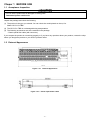
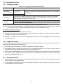
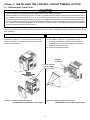
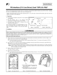
Instruction Manual High-Speed Serial Communication-Capable Terminal Block OPC-VG1-TBSI Thank you for purchasing our High-speed serial communication-capable terminal block designed for the high-performance, vector control FRENIC-VG series of inverters. - Improper handling might result in incorrect operation, a short life, or even a failure of this product. - Deliver this manual to the end user of this product. Keep this manual in a safe place until this product is discarded. - This manual does not contain the description of function codes or troubleshooting information. Read through this manual in conjunction with the FRENIC-VG User's Manual. Fuji Electric Co., Ltd. INR-SI47-1664JE -1- Preface Thank you for purchasing our High-speed serial communication-capable terminal block "OPC-VG1-TBSI." This instruction manual does not contain the description of function codes, troubleshooting information, or handling instructions of the inverter. Read through this manual in conjunction with the FRENIC-VG Instruction Manual and User's Manual to become familiar with proper handling and operation. Improper handling might result in incorrect operation, a short life, or even a failure of the "OPC-VG1-TBSI." Keep this manual in a safe place. Related Publications Listed below are the other materials related to the use of the OPC-VG1-TBSI. Read them in conjunction with this manual as necessary. • FRENIC-VG User's Manual • FRENIC-VG Instruction Manual The materials are subject to change without notice. Be sure to obtain the latest editions for use. • Read through this instruction manual to become familiar with this product before proceeding with installation, connections (wiring), operation, or maintenance and inspection. • Improper handling might result in incorrect operation, a short life, or even a failure of this product as well as the motor. • Deliver this manual to the end user of this product. Keep this manual in a safe place until this product is discarded. Safety precautions Read this manual thoroughly before proceeding with installation, connections (wiring), operation, or maintenance and inspection. Ensure you have sound knowledge of the device and familiarize yourself with all safety information and precautions before proceeding to operate the inverter. Safety precautions are classified into the following two categories in this manual. Failure to heed the information indicated by this symbol may lead to dangerous conditions, possibly resulting in death or serious bodily injuries. Failure to heed the information indicated by this symbol may lead to dangerous conditions, possibly resulting in minor or light bodily injuries and/or substantial property damage. Failure to heed the information contained under the CAUTION title can also result in serious consequences. These safety precautions are of utmost importance and must be observed at all times. Installation and wiring • Before starting installation and wiring, turn OFF the power and wait at least five minutes for inverters of 22 kW or below, or at least ten minutes for those of 30 kW or above. Make sure that the LED monitor and charging lamp are turned OFF. Further, make sure, using a multimeter or a similar instrument, that the DC link bus voltage between the terminals P(+) and N(-) has dropped to the safe level (+25 VDC or below). • Qualified electricians should carry out wiring. Otherwise, an electric shock could occur. • In general, sheaths of the control signal wires are not specifically designed to withstand a high voltage (i.e., reinforced insulation is not applied). Therefore, if a control signal wire comes into direct contact with a live conductor of the main circuit, the insulation of the sheath might break down, which would expose the signal wire to a high voltage of the main circuit. Make sure that the control signal wires will not come into contact with live conductors of the main circuit. Doing so could cause an accident or an electric shock. • Do not use the product that is damaged or lacking parts. Doing so could cause a fire, an accident, or injuries. -2- • Prevent lint, paper fibers, sawdust, dust, metallic chips, or other foreign materials from getting into the inverter and the OPC-VG1-TBSI. Otherwise, a fire or an accident might result. • Incorrect handling in installation/removal jobs could cause a failure. A failure might result. Operation • Be sure to mount the front cover before turning the power ON. Do not remove the cover when the inverter power is ON. Otherwise, an electric shock could occur. • Do not operate switches with wet hands. Doing so could cause an electric shock. • If you configure the function codes wrongly or without completely understanding the FRENIC-VG Instruction Manual and User's Manual, the motor may rotate with a torque or at a speed not permitted for the machine. Confirm and adjust the setting of the function codes before running the inverter. Otherwise, an accident could occur. Maintenance and inspection, and parts replacement • Before proceeding to the maintenance/inspection jobs, turn OFF the power and wait at least five minutes for inverters of 22 kW or below, or at least ten minutes for those of 30 kW or above. Make sure that the LED monitor and charging lamp are turned OFF. Further, make sure, using a multimeter or a similar instrument, that the DC link bus voltage between the terminals P(+) and N(-) has dropped to the safe level (+25 VDC or below). Otherwise, an electric shock could occur. • Maintenance, inspection, and parts replacement should be made only by qualified persons. • Take off the watch, rings and other metallic objects before starting work. • Use insulated tools. • Never modify the OPC-VG1-TBSI. Otherwise, an electric shock or injuries could occur. Disposal • Treat the OPC-VG1-TBSI as an industrial waste when disposing of it. Otherwise injuries could occur. Others • Never modify the OPC-VG1-TBSI. Doing so could cause an electric shock or injuries. -3- Chaper 1 BEFORE USE 1.1 Acceptance Inspection • Do not use the product that is damaged or lacking parts. Otherwise injuries could occur. Unpack the package and check the following. (1) The product is the type you ordered. You can check the model printed on the option. Model: OPC-VG1-TBSI (2) The OPC-VG1-TBSI is not damaged during transportation. (3) The following accessories are also contained in the package. - Plastic optical fiber cable (with connector) If you suspect the product is not working properly or if you have any questions about your product, contact the shop where you bought the product or your local Fuji branch office. 1.2 External Appearance Figure 1.2-1 Figure 1.2-2 External Appearance Plastic optical fiber cable -4- 1.3 Precautions for Use 1.3.1 Temporary storage Table 1.3-1 Storage and Transport Environments Item Storage temperature Specifications -25 to +70˚C (Note 1) Places not subjected to abrupt temperature changes or condensation or freezing. Relative humidity 5 to 95% (Note 2) Atmosphere The OPC-VG1-TBSI must not be exposed to dust, direct sunlight, corrosive or flammable gases, oil mist, vapor, water drops or vibration. The atmosphere must contain only a low level of salt. (0.01 mg/cm2 or less per year) Atmospheric pressure 86 to 106 kPa (during storage) 70 to 106 kPa (during transportation) (Note 1) Assuming comparatively short time storage, e.g., during transportation or the like. (Note 2) Even if the humidity is within the specified requirements, avoid such places where the OPC-VG1-TBSI will be subjected to sudden changes in temperature that will cause condensation to form. Precautions for temporary storage (1) Do not leave the OPC-VG1-TBSI directly on the floor. (2) If the environment does not satisfy the specified requirements listed in Table 1.3-1, wrap the OPC-VG1-TBSI in an airtight vinyl sheet or the like for storage. (3) If the OPC-VG1-TBSI is to be stored in a high-humidity environment, put a drying agent (such as silica gel) in the airtight package. 1.3.2 Long-term storage The long-term storage method of the OPC-VG1-TBSI varies largely according to the environment of the storage site. General storage methods are described below. (1) The storage site must satisfy the requirements specified for temporary storage. (2) The package must be airtight to protect the OPC-VG1-TBSI from moisture. Add a drying agent inside the package to maintain the relative humidity inside the package within 70%. (3) If the inverter equipped with the OPC-VG1-TBSI has been installed to the equipment or panel at construction sites where it may be subjected to humidity, dust or dirt, then temporarily remove the inverter and store it in the environment specified in Table 1.3-1. 1.3.3 Wiring precautions (1) Route the wiring of the control circuit terminals as far from the wiring of the main circuit as possible. Otherwise electric noise may cause malfunctions. (2) Fix the control circuit wires inside the inverter to keep them away from the live parts of the main circuit (such as the terminal block of the main circuit). -5- Chaper 2 INSTALLING THE CONTROL CIRCUIT TEMINAL OPTION 2.1 Removing the Front Cover • Incorrect handling in installation/removal jobs could result in a broken produce. • Before installing or removing the OPC-VG1-TBSI, shut down the input power to the inverter and make sure that the charging lamp is turned OFF. Even if all of the input power to the main circuit and control circuit and the auxiliary power are shut down, however, power is still applied to the inverter control terminals 30A, 30B, 30C, Y5A and Y5B when the external control circuit is supplied with power from a separate power supply. Shut down the power of the external equipment for prevention of electric shock. Shut down the power of the external equipment for prevention of electric shock. Remove the front cover from the inverter as shown below. The removal procedure differs depending on the inverter type (capacity). FRN30VG1S-2J/4J (30 kW) or upper types FRN22VG1S-2J/4J (22 kW) or lower types As shown in Figure 2.1-1, loosen the cover mounting screw on section "a" and pull out the upper end of the front cover towards you. (1) As shown in Figure 2.1-2, remove the cover mounting screws (the number of screws differs depending on the inverter capacity) on section "b" and remove the front cover. (2) Open the keypad enclosure. Keypad enclosure Control printed circuit board (Control PCB) a b Figure 2.1-1 Removing the Front Cover FRN22VG1S-2J/4J (22 kW) or lower types Figure 2.1-2 Removing the Front Cover FRN30VG1S-2J/4J (30 kW) or upper types -6- 2.2 Installing the OPC-VG1-TBSI The following options can be connected to F port (CN1) on the control printed circuit board (control PCB). Installation procedure (1) Loosen two screws (c) on the standard control circuit terminal printed circuit board and remove the board from F port (CN1) on the control printed circuit board. (2) Mount the OPC-VG1-TBSI. (3) Tighten two screws (d) to secure the OPC-VG1-TBSI in place. (4) Mount the control circuit teminal option. (5) Referring to Figures 2.1-1 and 2.1-2 “Removing the Front Cover,” reverse the removal procedure to mount the front cover. Control printed circuit board Control printed circuit board F port F port Control circuit terminal printed circuit board OPC-VG1-TBSI c d Figure 2.2.1 Removing the Control Circuit Terminal Printed Circuit Board Figure 2.2.2 Mounting the OPCOPC-VG1VG1-TBSI -7- History of revision Number Date of revision Remarks - June 2013 First edition Copyright 2013 Fuji Electric Co., Ltd. No part of this publication may be reproduced or copied without prior written permission from Fuji Electric Co., Ltd. All products and company names mentioned in this manual are trademarks or registered trademarks of their respective holders. The information contained herein is subject to change without prior notice for improvement. The purpose of this instruction manual is to provide accurate information in handling, setting up and operating of the OPC-VG1-TBSI. Please feel free to send your comments regarding any errors or omissions you may have found, or any suggestions you may have for generally improving the manual. In no event will Fuji Electric Co., Ltd. be liable for any direct or indirect damages resulting from the application of the information in this manual. Fuji Electric Co., Ltd. Gate City Ohsaki, East Tower, 11-2, Osaki 1-chome, Shinagawa-ku, Tokyo, 141-0032, Japan Phone: +81 3 5435 7058 Fax: +81 3 5435 7420 URL http://www.fujielectric.com/ 2013-06 -8-