1
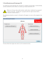
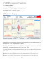
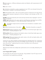
Instructions for use / installation
of the
boso profil-manager XD
Powerful software for computer-assisted
blood pressure control and observation of therapy
Compatible with the following blood pressure meters:
TM-2430
ABI-system 100
ABI-system 100 PWV
medicus PC2
medilife PC3
0124
These instructions for use and installation of the boso profil-manager XD apply to
version 4.2.0.128 and above. Please refer to the readme.txt file on the installation
CD for new information.
The drive letters in these instructions for use are simply examples:
C:\ for the local hard drive
D:\ for the CD/DVD drive
The path data corresponds to a standard single-user installation under the german
Windows 7 (32-bit) operating system and may be different in other operating systems or language versions.
Microsoft and Microsoft Windows are registered trademarks of the Microsoft Corporation.
2
Table of contents
1.1 1.1.1
1.1.2
1.2
1.2.1
1.2.2
1.2.2.1
1.2.2.2
1.2.2.3
1.2.2.4
1.3
1.4 2. 2.1 2.1.1 2.1.2 2.1.3 2.1.4 2.1.4.1 2.1.4.2
2.1.4.3
2.1.5
2.1.6 2.1.7 2.1.8 3. 3.1 3.2 3.2.1 3.2.2 3.2.3 3.2.4 3.2.5 3.2.6
3.3 3.3.1
3.4 3.4.1 3.4.2 3.4.3 3.4.4 3.4.5 3.4.6 Before installation....................................................................................7
Data backup............................................................................................7
Operating the software...........................................................................7
Installing boso profil-manager XD...........................................................8
Single-user version...................................................................................9
Networkversion.....................................................................................12
Installing the Firebird database server....................................................12
Installing the database file.....................................................................13
Installing boso profil-manager XD..........................................................13
Launching the network version for the first time....................................14
Converting data from profilmanager 3 and ABI.....................................15
Installing the USB connection cable.......................................................17
Start.....................................................................................................18
Patient registry, for all applications........................................................19
„New…“ button...................................................................................19
„Modify…“ button...............................................................................19
„Delete…“ button................................................................................19
„Export/Import“ button.........................................................................19
„Export Excel“ ......................................................................................19
„Export patient (XML)“ .........................................................................19
„Import patient (XML)“.........................................................................20
„Import GDT“.......................................................................................20
„Settings…“ button..............................................................................20
„Print…“ button...................................................................................20
„Billing assistance“ button....................................................................21
„ABI/PWV measurement“ application...............................................22
„Patient“ registry..................................................................................22
„Measurements“ registry......................................................................22
„Delete“ button....................................................................................23
„Export GDT“ button............................................................................23
„Remarks…“ button.............................................................................24
„Print“ button.......................................................................................24
„ABI measurement“ button...................................................................25
„ABI+PWV measurement“ button.........................................................25
„Profiles“ registry..................................................................................26
„Print“ button.......................................................................................27
„Settings...“ button in „Patient“ registry...............................................28
„Doctor“ sub-registry............................................................................28
„Import/Export“ sub-registry.................................................................29
„Classification“ sub-registry..................................................................30
„Test mode“ sub-registry......................................................................31
„Printer settings“ sub-registry................................................................32
Error-codes............................................................................................32
3
4. 4.1 4.2 4.2.1 4.2.2 4.2.3 4.2.4 4.2.5 4.2.6 4.3 4.3.1 4.3.2 4.3.3 4.3.4 4.4 4.4.1 4.4.2 4.4.3 4.4.4 4.5 4.5.1 4.5.2 4.5.3 4.5.4 4.6 4.6.1 4.6.2 4.7 4.7.1 4.7.2 4.7.3 4.7.4 4.7.5 4.7.6 5. 5.1 5.2 5.2.1 5.2.2 5.2.3 5.2.4 5.2.5 5.2.6
5.2.7 5.2.8 „24-hour measurement“ application................................................. 33
„Patient“ registry.................................................................................. 33
„Measurements“ registry...................................................................... 33
„Delete period“ button......................................................................... 36
„Export GDT“ button............................................................................ 36
„Manual data“ button.......................................................................... 36
„Print...“ button.................................................................................... 36
„Initialise“ button.................................................................................. 37
„Trasfer data“ button............................................................................ 39
„Sys/dia profile“ registry........................................................................ 40
„Modify“ button................................................................................... 40
„Reference chart“ button...................................................................... 40
„Time scope“ selection field.................................................................. 41
„Print…“ button................................................................................... 41
„MAP profile“ registry........................................................................... 42
„Modify“ button................................................................................... 42
„Reference chart“ selection field........................................................... 42
„Time scope“ selection field.................................................................. 43
„Print…“ button................................................................................... 43
„Profil PP profile“ registry...................................................................... 44
„Modify“ button................................................................................... 44
„Reference chart“ selection field........................................................... 45
„Time scope“ selection field.................................................................. 45
„Print…“ button................................................................................... 45
„Statistics” button................................................................................. 46
„Modify“ button................................................................................... 47
„Print…“ button................................................................................... 47
„Settings..." button in „Patient“ registry.............................................. 48
„Doctor“ sub-registry............................................................................ 48
„Import/export“sub-registry.................................................................. 49
„Printer settings“sub-registry................................................................. 50
„Interface“sub-registry.......................................................................... 51
„Limits“sub-registry............................................................................... 52
„Profile“sub-registry.............................................................................. 53
„Patient measurement“ application.................................................. 54
„Patient“ registry.................................................................................. 54
„Measurements“ registr........................................................................ 54
„Delete period“ button......................................................................... 56
„Export GDT“ button............................................................................ 56
„Manual data“ button.......................................................................... 56
„Print...“ button.................................................................................... 56
„Trasfer data“ button............................................................................ 57
„Interval limits“ button.......................................................................... 58
„All, Morning, Afternoon“ selection...................................................... 58
„Period“ selection................................................................................. 58
4
5.3 „Sys/dia profile“ registry........................................................................ 59
5.3.1 „All, Morning, Afternoon“ selection...................................................... 59
5.3.2 „Period“ selection................................................................................. 60
5.3.3 „Time scope“ selection field.................................................................. 60
5.3.4 „Print...“ button.................................................................................... 60
5.4 „MAP profile“ registry........................................................................... 61
5.4.1 „All, Morning, Afternoon“ selection...................................................... 61
5.4.2 „Period“ selection................................................................................. 62
5.4.3 „Time scope“ selection field.................................................................. 62
5.4.4 Print...“ button...................................................................................... 62
5.5 „PP profile“ registry............................................................................... 63
5.5.1 „All, Morning, Afternoon“ selection...................................................... 63
5.5.2 „Time scope“ selection field.................................................................. 64
5.5.3 „Period“ selection................................................................................. 64
5.5.4 „Print...“ button.................................................................................... 64
5.6 „Statistics” button................................................................................. 65
5.6.1 „Print...“ button.................................................................................... 66
5.7 „Settings..." button in „Patient“ registry.............................................. 67
5.7.1 „Doctor“ sub-registry............................................................................ 67
5.7.2 „Import/export“sub-registry.................................................................. 68
5.7.3 „Printer settings“sub-registry................................................................. 69
5.7.4 „Interface“sub-registry.......................................................................... 70
5.7.5 „Limits“sub-registry............................................................................... 71
5.7.6 „Profile“sub-registry.............................................................................. 72
6. Warranty provisions........................................................................... 73
7. Limitation of liability.......................................................................... 74
8. Explanation of symbols...................................................................... 74
Appendix A – Extract from GDT record description.......................................... 75
5
Contents of package
1 installation CD
1 user manual
Minimum operating requirements:
• Pentium II or higher
• 512 MB RAM
• Graphics card
• 100 MB free hard disk space
• USB 1.1 interface
• Microsoft Windows® XP
Purpose
software, utilized for
• management of values which are generated by measuring instruments boso
• archive of measured values in a separate database
• data exchange with doctors' EDP systems via GDT interface
• programming of 24-blood pressure instruments (interval limits, interval time, maximum inflation pressure)
• control of ABI measurement systems (start and termination of a measurement)
6
1.1 Before installation…
You have chosen boso profil-manager XD, a software solution which gives you optimum results with minimum input time. It has been deliberately designed to be operated without the usual menu structure based on individual registries. This is why the
user manual also refers to individual windows and program parts as registries.
1.1.1 Data backup
To avoid losing data, you should back up the ‘profman.fdb’ file from the
C:\ProgramData\Boso\profmanXD\ sub-directory at regular intervals.
1.1.2 Operating the software
The program is operated by the mouse.
PC requirements Computers used to assess data must comply with the latest version of European standard EN 60601-1.
7
1.2 Installing boso profil-manager XD
To install boso profil-manager XD, start file D:\ installer.exe manually or automatically
via the autostart function which runs when you have inserted the CD.
Make sure that you have administrator rights when installing the program (if
in doubt, start the “installer.exe” program with the right mouse button,
“execute as administrator”)
The following selection screen (in German) will appear as soon as the program has
started:
Choose either the single-user version or the network version.
8
1.2.1 Single-user version
The single-user version is the correct choice if you are only going to run the program on
one computer. In this case you do not need to install a separate Firebird database server
(an embedded Firebird is used). Follow the installation assistant instructions:
Select your preferred language for installation (screenshot in German):
The available languages are German, English and French.
As the program can be used with all current boso PC devices, in the next mask you
must select the type of device to be activated when starting the program for the first
time. After installation you can switch between device types at any time while using
the program.
9
You can change the target folder for installation individually, but in most cases the
default folder is used unchanged:
10
At the end of installation, tick the “Install boso USB Driver” checkbox to install the USB
driver needed for the PC connection cable.
Once you have successfully installed the single-user version of boso profil-manager XD,
click on the “Close” button to close the installation screen.
11
1.2.2 Network version (screenshot in German)
The network version is the correct choice if you are going to run the program on multiple workstations in a network. Here the database can be stored at any location in the
network.
1.2.2.1 Installing the Firebird database server
In order to run the network version of boso profil-manager XD, the Firebird database
server must be installed on the computer where the database is to be stored.
Click on the “Install Firebird DB server” button to install the Firebird database server.
After selecting the language, follow the instructions given by the installation
assistant and accept all the default settings
12
1.2.2.2 Installing the database file
The “profman.fdb” database file can be stored at any location in the network.
Make sure that the computer in which the database is to be located is run
ning a current Firebird server (version 2.5 or above), that the TCP port 3050
is open for access when the firewall is active, and that access to the database
and the database server is not blocked by an anti-virus program.
1.2.2.3 Installing boso profil-manager XD
You can install boso profil-manager XD on any computer in the network by clicking the
“Install boso profil-manager XD” button.
Follow the instructions given by the installation assistant as described for the [singleuser version] in chapter 1.2.1.
13
1.2.2.4 Launching the network version for the first time
When you launch the network version for the first time, you will see a login window to
register with the Firebird database.
The login data you enter here will be stored in the “profman.ini” file in the C:\Programme\
Boso\ProfmanXD\ directory and can be modified if necessary at any time, for instance
if the database is moved to another location in the network.
Server name
Name of the server in which the database is located
Database file
Drive, path and name of the boso profil-manager XD database file from the server’s perspective.
User name
Login information for the current Firebird database server. The default name is “sysdba”.
Login information may be different if Firebird has already been installed.
Password
Login information for the current Firebird database server. The default password
is “masterkey”. Login information may be different if Firebird has already been
installed.
14
1.3 Converting data from boso profil-manager 3 and ABI
Use the Konverter.exe program to convert existing data from earlier Firebird databases.
Launch the program either via Windows Explorer from the directory path C:\Programme\
Boso\ProfmanXD\ or via the Windows start button, selecting the program “Transfer
data from boso profil-manager 3” under the “boso profil-manager XD” program group
(file path in German)
The databases to be converted must be on the local system. Conversion via the network is not possible.
15
Enter a username and password to register with the Firebird database server. The default
username is “sysdba” and the default password is “masterkey”.
Select the storage location for the profil-manager XD file in the “Target DB (profilmanager XD)” field.
Select the storage location of the database you want to convert (ABI or profil-manager
3). Click on the “Connect” button to connect to the source database.
Once you have established a connection with the source database, start transferring
data by clicking on the button of the same name (“Start transfer”) (screenshot in
German).
If you transfer data from both ABI and profil-manager 3, the separate sets of data are
brought together in the new database.
Measurements for a specific patient are only brought together if the surname, first
name and date of birth are the same. If the patient numbers are different, the patient
number of the target database is retained.
If the surname, first name and date of birth do not match, or if these fields are empty
or out of date, a new patient record will be created. The patient number is retained
unless it already exists in the target database, in which case a new patient number will
be created.
16
All patients with mismatches are transferred to a list. The data can be updated before
being transferred. Missing or out-of-date data will not be transferred (screenshot in
German).
1.4 Installing the USB connection cable
If the USB driver was pre-installed during installation (this is normally the case), you
simply need to plug the USB connection cable provided into a free USB port. The cable
is then automatically recognised and installed.
If the driver was not pre-installed, you must execute the file dpinst_32bit.exe (present
after installation in the directory C:\Programme\Boso\profmanXD\ftdi\) as administrator
and then plug the USB cable into a free USB port.
17
2. Start
After starting boso profil-manager XD by clicking on the "boso profil-manager XD"
icon, select the part of the program you wish to run in the light of the device application you are currently using:
Applications with data already stored are indicated by the symbol.
Applications with no data at present are indicated by the
symbol.
If you switch from one application to another for a selected patient, the “Measurements”
registry is automatically selected. This means that measurements from various applications provide you with an overall view of all measurements for a particular patient.
18
Accessing the help function
Press the F1 key or format at any time.
button to call up these and other instructions for use in PDF
2.1 Patient registry, for all applications
Click on a patient to select him or her.
Patients can be sorted by clicking on the header of the relevant column.
Use the “Restore column order” function to go back to the original sorting by patient
number. To do this, right-click in the header row of the patient table.
You can search by name via the “Search” function.
2.1.1 “New…” button
This sets up a new patient. The name and patient number fields must be completed.
The system will suggest a patient number, but you can change this manually.
2.1.1 “Modify…” button
This alters an existing patient’s personal data.
2.1.1 “Delete…” button
This deletes a patient.
This process is irreversible: all data (including measurements from all parts of
the application) are deleted and cannot be recovered.
2.1.4 “Export/Import” button
2.1.4.1 “Export Excel” exports data for the currently selected patient (from the current
ABI, 24-hour, patient measurement application) in Excel-readable .xls format. You can
choose whatever file name and storage location you like.
2.1.4.2 “Export patient (XML)” exports data for the currently selected patient in
profil-manager XD-readable .xml format.
19
2.1.4.3 “Import Patient (XML)” imports data for a selected patient.
The following rules apply to 2.1.4.2 and 2.1.4.3:
The transfer path from the transfer file settings is used for incorporation into the clinic’s
data processing system (see next chapter, “Settings…” button)
The file name is made up of the active application and the patient number.
For example, “2430_10.xml” stands for patient data for the patient with patient number
10 from the 24-hour measurement application.
2430_#.xml stands for data from the 24-hour measurement
ABI_#.xml stands for data from the ABI measurement
medicus_#.xml stands for data from patient measurement
2.1.5 Import GDT
The GDT-import file, if available, is read and the included patient is selected or created. If a patient with the imported patient number already exists, the following screen
appears.
The button "Yes, select this patient" selects the indicated patient.
With the button "No, use patient data from GDT import" all existing data
will be assigned to the patient from the GDT import file.
20
2.1.6 “Settings” button
The settings are explained in the sections dealing with particular applications (chapters
3 to 5) as they are application-specific.
2.1.7 “Print…” button
Patient data is presented on screen (preview), printed out on the printer selected under
“Setup”, and/or in the configured PDF file.
The Windows standard printer is the default for print-outs.
If you selected “PDF file” in the printer settings, a PDF file will be created. The name of
this PDF file is pmXD_pat#.pdf
Where
pat#=patient number
2.1.8 “Billing assistance…” button
This creates a summary of the number of measurements in the currently selected application that have been performed within a given time period (not available for patient
measurement).
For example, this provides a simple indication of how many 24-hour measurements
were performed in the first quarter.
If you selected “PDF file” in the printer settings, a PDF file will be created. The name of
this PDF file is pmXD_cl.pdf.
21
3. “ABI/PWV measurement” application
3.1 “Patient” registry
see section “2.1 Patient registry, for all applications”
See chapter 3.4 for "Settings" button
3.2 “Measurements” registry
Measurements that have been carried out can be viewed, and new measurements can
be performed, in the “Measurements” registry.
To display ABI / PWV measurements that have already been carried out, select the
desired ABI / PWV measurements in the “Date-Time” field.
The screen displays the following parameters (for the left and right half of the body in
each case):
Sys upper arm systolic blood pressure, with measurements >140 mmHg in red
Dia upper arm diastolic blood pressure, with measurements >90 mmHg in red
22
PP pulse pressure = difference between systole and diastole, with measurements >54
mmHg in red
Pul pulse in 1/min
Arr Indication of whether a pulse irregularity of over 25% was observed during the
measurement. Display in red indicates arrhythmia.
ABI Ankle-brachial index = ratio of the systolic pressure measured in the leg and the
higher systolic pressure measured in the arm. Display in red indicates an ABI < 0.9
[default].
baPWV (optional) measured pulse wave velocity brachial-ankle, displayed in red indicates >= 14,5 m/s.
cfPWV_calc (optional) pulse wave velocity carotid-femoral calculated from baPWV,
displayed in red indicates >= 10 m/s. (No calculation if both ABI < 0.9)
The patient’s height must be recorded as this information is needed to calculate PWV.
Sys systolic blood pressure in the ankle Note the information on page 25.
Diff Arm Sys Difference between the systolic values in the left and right upper arms,
with results > 10mmHg displayed in red
Diff Arm Dia Difference between the diastolic values in the left and right upper arms,
with results > 10mmHg displayed in red
Diff Leg Sys Difference between the systolic values in the left and right ankles, with
results > 10mmHg displayed in red.
Clicking on one of the oscillation profiles enlarges the selected profile. The “pulse level
over time” registry shows the course of oscillation over the time axis. The “pulse level
over cuff pressure” registry shows the course of oscillation over cuff pressure.
3.2.1 “Delete” button
Measurements that have already been performed can be irrevocably deleted by this
button.
3.2.2 “Export GDT” button
This generates the GDT export file manually. Only available if the GDT import of the
active patient has already been performed.
23
3.2.3 “Remarks…” button
Click in the “Remarks” field or the “Remarks” button to add a remark to a measurement.
Remarks that are made frequently can be stored as templates using the “Store as
template” button. You can use the “Remark templates” button to easily insert stored
remark templates into a remark field at any time.
Measurements with remarks are marked with an "R" in the "Date-Time" field.
3.2.47 “Print” button
This produces a print-out of the current measurement.
If you selected “PDF file” in the printer settings, a PDF file will be created.
The name of this PDF file is ABI_pat#_YYYYMMDD_m.pdf
where
pat#=patient number
YYYYMMDD = date of measurement
m = measurement reference letter
24
3.2.5 “ABI measurement” button
This initialises the boso ABI system 100 and starts a new measurement.
You can cancel a measurement which is being performed at any time by using the
“Cancel measurement” button or pressing the STOP key on the device.
Once the measurement of a limb has been completed, the “Store measurement” key
is activated.
You could store the measurement at this stage (for example, if the patient has a limb
missing).
Once all measurements on four limbs have been completed, a green border appears
around the active “Store measurement” button. This indicates that the measurements
have been successfully completed and can be stored.
If an error occurs during a measurement, the following error message appears in the
corresponding measurement window:
(82) measurement error -> retry measurement.
If this error occurs repeatedly, this can indicate that the patient has a vascular
disease. Further investigation is recommended in this case once a technical defect
has been ruled out. If no reading is displayed for systolic blood
pressure in the ankle, check the cuff and tubes and then retry. If no
reading is displayed the second time, this can indicate a circulation dis
order or medial sclerosis. Here again further investigations are recommended.
(83) Connect cuff
(89) System error -> Device should be checked by the manufacturer’s technical support
service
3.2.6 “ABI+PWV measurement” button (optional)
This automatically performs a PWV measurement 10 seconds after completion of the
ABI measurement described under 3.2.5.
A green border appears around the “Store measurement” button once the PWV
measurement has been completed. This indicates that the PWV measurement has
been successfully completed and can be stored.
25
3.3 “Profiles” registry
The ABI values (and PWV values if this option is selected) of all measurements are presented in the form of bar charts in the “Profiles” registry. The ABI colour display is as
per the setting under "Classification"
(red: ABI < 0.9).
Various parameters are available to alter the optical presentation of the profile:
26
Display values (standard): ABI values are displayed above the bars.
Legend: The legend for the readings is displayed in the diagram.
3D: The bars are displayed in 3D.
Grid lines: Grid lines are shown in the coordinates system.
90° title: The title of the x-axis is rotated through 90°.
3.3.1 “Print” button
This produces a print-out of the profile display.
If you selected “PDF file” in the printer settings, a PDF file will be created. The name of
this PDF file is ABI_pat#_p.pdf
where
pat#=patient number
p = profile reference letter
27
3.4 “Settings...” button in “Patient” registry
3.4.1 “Doctor” sub-registry
The personal details of the doctor treating the patient are entered in the “Doctor”
registry and used to produce the footer in the print-out.
28
3.4.2 “Import/Export” sub-registry
If you are using a clinic data processing system that supports the GDT interface, this is
where the path and file names for export and import files are set.
You have direct access to the Windows directory structure via the buttons next to the
input fields for import and export files.
For example: c:\prax_edv\import.gdt
Import file = clinic DP system export file
Export file = clinic DP system import file
GDT import takes place automatically when you start the program, or manually by
clicking the “Export/Import -> Import GDT” button if a valid GDT import file is present
in the relevant directory.
GDT export takes place only if the patient being imported from the clinic DP system
is active. Export takes place automatically when the program is closed down (if measurements have been read in from the device during the current program session) or
can be performed manually at any time by clicking the "Export GDT" button in the
"Measurements" registry.
Data export is deactivated if another patient has been selected after automa
tic import. It is reactivated when the first patient is reselected. Data export is
also deactivated if no import has first taken place.
29
For certain applications (e.g. HL7 in hospital), it may be necessary to activate GDT-export
permantly and name the export file variable (Export.gdt -> yyyymmdd_hhmmss.gdt).
For this, activate the option "GDT export is permanently active - including variable file
name".
If this option is selected, precautions must be taken (check patient number)
to avoid incorrect allocation of readings.
With the active option "produce PDF file during GDT export" a PDF-file is created
with the GDT export.
3.4.3 “Classification” sub-registry
Limits for ABI value classification can be amended here. Modifications do not take effect until the program is restarted.
30
3.4.4 “Test mode” sub-registry
Clicking on the “pressure sensors A” or “pressure sensors B” button switches the ABI
system 100 into test mode. Clicking on the “End test” button ends test mode.
This function is needed for various purposes, for example testing pressure during metrology tests.
(optional)
Special simulators are needed to perform functional tests of the device with the “PWV”
option, and these tests must be carried out on the manufacturer's premises.
The activation of the “presure sensors B” is only possible for devices with a serial number upper 466 20000.
31
3.4.5 “Printer settings” sub-registry
In the “Printer settings” registry you decide whether the print-out should be produced
in paper form, as a screen print and/or as a PDF document, once the relevant [Print…]
buttons have been clicked while the program is running.
If you select “Printer”, then the “Output Options” dialogue appears when you click
on the [Print...] buttons while the program is running. You can choose either a print
output (“Printer”) or a screen view (“Preview”).
If you select “PDF file”, a PDF file is produced. The name of this PDF file is created
in different ways depending on the application, and this process is described in more
detail in the individual applications.
You must select at least one medium: “Printer” or “PDF file”.
If you select the “monochrome” option, the print will be in black and white.
32
4. “24-hour measurement” application
4.1 “Patient” registry
see section “2.1 Patient registry, for all applications”
See chapter 4.7 for "Settings" button.
4.2 “Measurements” registry
All measurements that have been read in to date for the selected patient are displayed
here.
33
This is where the TM-2430 is initialised and data is read out from the device.
A patient must be selected before you can switch to this registry. When the program
starts, no patient is selected. If you have not selected a patient manually, or imported
a patient automatically via the GDT interface, you will see this help mask:
The “Select from list” button shows you a list of all available patients so that you can
select the appropriate patient manually.
The “Read out patient from device” button identifies the patient you want to select via
the patient number stored in the device.
Both the period and the blood pressure meter with which the series of measurements
was carried out are displayed.
Select the appropriate period.
34
1
2
3
4
5
6
7
8
9
10
The column content is as follows:
1: serial numbers of measurements
2: date and time of measurement
3: SYS = systolic blood pressure
4: DIA = diastolic blood pressure
5: PUL = pulse
6: MAP = mean arterial blood pressure, calculated as DIA + 1/3 pulse pressure
7: PP = pulse pressure (SYS – DIA)
8: Exclude = if you highlight this, the measurement will not be taken into account for
assessment in the profile and statistics
9: S = measurement performed at night
10: Remark. Double-click in the measurement line to add a remark to a measurement.
This opens the remark input field:
35
4.2.1 “Delete period” button
This irrevocably deletes a complete set of readings.
4.2.2 “Export GDT” button
This generates the GDT export file manually. Only available if the GDT import of the
active patient has already been performed.
4.2.3 “Manual data” button
This allows you to add new readings to the active set of readings, or process or delete
them.
4.2.4 “Print…” button
This prints out the list of readings.
If you selected “PDF file” in the printer settings (chapter 4.7.3), a PDF file will be created.
The name of this PDF file is tm_pat#_YYYYMMDD_m.pdf
where
pat#=patient number
YYYYMMDD = date of measurement
m = measurement reference letter
36
4.2.5 “Initialise” button
The TM-2430 device can be initialised with a unique patient number up to 10 characters
in length. The benefit of this is that measurements can be immediately assigned to the
correct patient when they are read out.
The current patient is automatically transferred to the programming window, and the
patient number is assigned to the device (the software generates a numerical identifier,
which means that alphanumerical patient numbers can also be used in profil-manager
XD).
You can specify a maximum inflation pressure in the “Max. infl. press.” field. The blood
pressure meter will then not inflate beyond the figure you have set here.
If the patient’s systolic blood pressure is close to or above this figure, it will not be possible to measure blood pressure. The device then produces an error message.
The patient number programming and pressure restriction features are not
available on TM-2430 devices with serial numbers below SN M 0713550.
37
Three different modes can be programmed.
Standard periods / intervals
When this mode is selected, the device takes a reading every 15 minutes between 7
a.m. and 10 p.m., and every 30 minutes between 10 p.m. and 7 a.m.
Sleep button
In this mode the patient can decide when the night and day intervals should begin, by
pressing the black button
on the TM-2430 blood pressure meter. The benefit
of this programming feature is that it allows measurement intervals to be tailored to
the patient. For example, for patients with irregular sleep patterns.
The interval durations are 15 minutes (day interval) and 30 minutes (night interval).
Programmable periods / intervals
Two intervals and periods can be programmed according to individual preference in this
mode. The interval duration can be set as 5, 10, 20, 30, 60 or 120 minutes.
Display reading
Activating or deactivating this command determines whether or not the reading is
displayed after the measurement has been performed.
Set system time
Activating this command transfers the date and time settings on your PC.
38
4.2.6 “Transfer data” button
Connect the meter to the PC connection cable before activating the “data transfer”
button. Measurements are transferred from the meter which is connected.
Once data has been transferred, the interval limits can be adapted individually to the
patient's actual daily routine by clicking the "Modify" button.
Clicking the “Yes” button clears the device’s data memory.
39
4.3 “Sys/dia profile” registry
This displays the blood pressure trend.
The pulse trend can be displayed or hidden by the Ctrl+P key combination.
Move the cursor over the measurement to obtain more information about individual
readings. The date, time and reading are displayed in the top left-hand corner of the
diagram.
4.3.1 “Modify” button
Interval limits can be adapted individually to the patient's actual daily routine by clicking
the "Modify" button.
4.3.2 “Reference Chart” button
Clicking this reads in data from an additional 24-hour measurement into the current
graph, so that the two sets of measurements can be compared directly.
40
4.3.3 “Time scope” selection field
This allows you to select the period for which measurements are displayed. You have
the choice of Auto or Day.
“Auto” is the default setting. In this setting, the time scope is scaled from the first
measurement to the last.
In the “Day" setting, exactly 24 hours are displayed.
Right-clicking in the diagram allows you to shift the graph horizontally with the
mouse.
4.3.4 “Print…” button
This produces a print-out of the SYS/DIA profile, pulse profile and statistics.
If you selected “PDF file” in the printer settings (chapter 4.7.3), a PDF file will be created.
The name of this PDF file is tm_pat#_YYYYMMDD_sys.pdf
where
pat#=patient number
YYYYMMDD = date of measurement
SYS/DIA reference letter
41
4.4 “MAP profile” registry
This displays the trend for the calculated mean arterial blood pressure.
(MAP = diastole DIA + 1/3 pulse pressure PP)
The pulse trend can be hidden or displayed by the Ctrl+P key combination.
Move the cursor over the measurement to obtain more information about individual
readings. The date, time and reading are displayed in the top left-hand corner of the
diagram.
4.4.1 “Modify” button
Interval limits can be adapted individually to the patient's actual daily routine by clicking
the "Modify" button.
4.4.2 “Reference Chart” selection field
Clicking this reads in data from an additional 24-hour measurement into the current
graph, so that the two sets of measurements can be compared directly.
42
4.4.3 “Time scope” selection field
This allows you to select the period for which measurements are displayed. You have
the choice of Auto or Day.
“Auto” is the default setting. In this setting, the time scope is scaled from the first
measurement to the last.
In the “Day" setting, exactly 24 hours are displayed.
Right-clicking in the diagram allows you to shift the graph horizontally with the
mouse.
4.4.4 “Print…” button
This produces a print-out of the MAP profile, pulse profile and statistics.
If you selected “PDF file” in the printer settings (chapter 4.7.3), a PDF file will be created.
The name of this PDF file is tm_pat#_YYYYMMDD_map.pdf
where
pat#=patient number
YYYYMMDD = date of measurement
map = MAP reference letter
43
4.5 “PP profile” registry
This displays the trend for the calculated pulse pressure. (PP = SYS-DIA)
The pulse trend can be hidden or displayed by the Ctrl+P key combination.
Move the cursor over the measurement to obtain more information about individual
readings. The date, time and reading are displayed in the top left-hand corner of the
diagram.
4.5.1 “Modify” button
Interval limits can be adapted individually to the patient's actual daily routine by clicking
the "Modify" button.
44
4.5.2 “Reference Chart” selection field
Clicking this reads in data from an additional 24-hour measurement into the current
graph, so that the two sets of measurements can be compared directly.
4.5.3 “Time scope” selection field
This allows you to select the period for which measurements are displayed. You have
the choice of Auto or Day.
“Auto” is the default setting. In this setting, the time scope is scaled from the first
measurement to the last.
In the “Day" setting, exactly 24 hours are displayed.
Right-clicking in the diagram allows you to shift the graph horizontally with the
mouse.
4.5.4 “Print…” button
This produces a print-out of the pulse pressure profile, pulse profile and statistics.
If you selected “PDF file” in the printer settings (chapter 4.7.3), a PDF file will be created.
The name of this PDF file is tm_pat#_YYYYMMDD_pp.pdf
where
pat#=patient number
YYYYMMDD = date of measurement
pp = pulse pressure reference letter
45
4.6 “Statistics” registry
Measurements for the total period, daytime and nighttime periods are assessed separately.
The total value of the readings are displayed in the individual periods.
The following values are shown in the individual columns:
Min: smallest value in the interval in question
Mean: arithmetic mean in the interval in question
Max: largest value in the interval in question
SD: standard deviation in the interval in question
> Limit: percentage above the limits that have been set
MBPS: morning blood pressure surge
The MBPS indicates the rise in blood pressure after getting up.
MBPS = MwSysDay - MwSysNight
where
MwSysDay = average of systolic values in the first two hours of the daytime interval
46
MwSysNight = average of the three systolic values surrounding the lowest systolic value
in the nighttime interval (one value before the lowest value, the lowest value itself and
one value after the lowest value).
The percentage increase/decrease during the night is displayed.
4.6.1 “Modify” button
Interval limits can be adapted individually to the patient's actual daily routine by clicking
the "Modify" button.
4.6.2 “Print…” button
This produces a print-out of the SYS/DIA profile, pulse profile and statistics.
If you selected “PDF file” in the printer settings (chapter 4.7.3), a PDF file will be created.
The name of this PDF file is tm_pat#_YYYYMMDD_sys.pdf
where
pat#=patient number
YYYYMMDD = date of measurement
sys = SYS/DIA reference letter
47
4.7 “Settings...” button in “Patient” registry
4.7.1 “Doctor” sub-registry
The personal details of the doctor treating the patient are entered in the “Doctor”
registry and used to produce the footer in the print-out.
48
4.7.2 “Import/Export” sub-registry
If you are using a clinic data processing system that supports the GDT interface, this is
where the path and file names for export and import files are set.
You have direct access to the Windows directory structure via the buttons next to the
input fields for import and export files.
For example: c:\prax_edv\import.gdt
Import file = clinic DP system export file
Export file = clinic DP system import file
GDT import takes place automatically when you start the program, or manually by
clicking the “Export/Import -> Import GDT” button if a valid GDT import file is present
in the relevant directory.
GDT export takes place only if the patient being imported from the clinic DP system
is active. Export takes place automatically when the program is closed down (if measurements have been read in from the device during the current program session) or
can be performed manually at any time by clicking the "Export GDT" button in the
"Measurements" registry.
Data export is deactivated if another patient has been selected after automa
tic import. It is reactivated when the first patient is reselected. Data export is
also deactivated if no import has first taken place.
Further informations to the available options "Produce PDF file during GDT-export"
and "GDT export permanently active" see 3.4.2 .
49
4.7.3 “Printer settings” sub-registry
In the “Printer settings” registry you decide whether the print-out should be produced
in paper form, as a screen print and/or as a PDF document, once the relevant [Print…]
buttons have been clicked while the program is running.
If you select “Printer”, then the “Output Options” dialogue appears when you click on
the [Print...] buttons while the program is running. You can choose either a print output
(“Printer”) or a screen view (“Preview”). The “File” function has no significance here.
If you select “PDF file”, a PDF file is produced. The name of this PDF file is created
in different ways depending on the application, and this process is described in more
detail in the individual applications.
You must select at least one medium: “Printer” or “PDF file”.
If you select the “monochrome” option, the print will be in black and white.
If you press the “Configured print-out” printer symbol, the print-out format configured
here will be used and only the selected pages will be printed.
50
4.7.4 “Interface” sub-registry
This is where you determine how the connection between the blood pressure meter
TM-2430 and the PC is established.
If the “Automatic USB selection” is active, the software always checks which USB port
a TM-2430 device is connected to before data transfer. If more than one device is
connected at the same time, please disconnect all devices apart from the one that you
want to use. You will see a warning telling you to do this.
If the “Automatic USB selection” option is not active, the serial (COM) or USB port
selected in the port list will be used for data transfer.
Older models have a more limited set of instructions (no programmable patient number
or maximum inflation pressure). Select the appropriate option for devices with serial
numbers below SN M0713551.
51
4.7.5 “Limits” sub-registry
The limits for the individual periods can be set in order to allow customised assessment.
The day and night limit settings relate to the interval periods that have been set.
52
4.7.6 “Profile” sub-registry
In the profile displays (“Sys/Dia, MAP, PP profile” registry), an envelope curve (line
connecting the individual measurements) is normally drawn, with the limits shown as
horizontal lines.
Both the envelope curve and the limit lines can be hidden.
53
5. “Patient measurement” application
5.1 “Patient” registry
see section “2.1 Patient registry, for all applications”
See chapter 4.7 for "Settings" button.
5.2 “Measurements” sub-registry
All measurements that have been read in to date for the selected patient are displayed
here. Both the period and the blood pressure meter with which the series of measurements was carried out are displayed.
54
1
2
3
4
5
6
7 8
9
10
The column content is as follows:
1: serial numbers of measurements
2: date and time of measurement
3: SYS = systolic blood pressure
4: DIA = diastolic blood pressure
5: PUL = pulse
6: MAP = mean arterial blood pressure, calculated as DIA + 1/3 pulse pressure
7: PP = pulse pressure (SYS – DIA)
8: Arr. = indication of arrhythmia
9: Exclude = if you highlight this, the measurement will not be taken into account for
assessment in the profile and statistics
10: Remark. Double-click in the measurement line to add a remark to a measurement.
This opens the remark input field:
55
5.2.1 “Delete period” button
This irrevocably deletes a complete set of readings.
5.2.2 “Export GDT” button
This generates the GDT export file manually. Only available if the GDT import of the
active patient has already been performed.
5.2.3 “Manual data” button
Additional readings can be added to the active set of readings here.
5.2.4 “Print…” button
This prints out the list of readings.
If you selected “PDF file” in the printer settings (chapter 5.7.3), a PDF file will be created.
The name of this PDF file is medi_pat#_YYYYMMDD_m.pdf
where
pat#=patient number
YYYYMMDD = date of measurement
m = measurement reference letter
56
5.2.5 “Transfer data” button
Connect the meter to the PC.
Once you have clicked on the “Transfer data" button, the START/STOP button on the
blood pressure meter must be pressed within 6 seconds in order to transfer data from
the blood pressure meter. Measurements will be transferred from the meter which is
connected.
Once data has been successfully transferred, you can set up a new period or assign the
data to an existing period.
57
5.2.6 “Interval limits” button
The limits for morning and afternoon measurements can be defined here. The default
setting is midnight to 11.59 a.m. for morning and noon to 11.59 p.m. for afternoon.
5.2.7 “All, Morning, Afternoon” selection
You can restrict the reading selection to only morning measurements or only afternoon
measurements here.
5.2.8 “Period” selection
You can select a specific period for assessment among all the readings by selecting a
period.
Click on the arrow symbol in the data fields to open a calendar, making selection
easier.
Click on the month or year to change it immediately.
58
5.3 “Sys/dia profile” registry
This displays the blood pressure trend.
The pulse trend can be hidden or displayed by the Ctrl+P key combination.
Move the cursor over the measurement to obtain more information about individual
readings. The date, time and reading are displayed in the top left-hand corner of the
diagram.
5.3.1 “All, Morning, Afternoon” selection
You can restrict the reading selection to only morning measurements or only afternoon
measurements here.
59
5.3.2 “Period” selection
You can select a specific period for assessment among all the readings by selecting a
period.
Click on the arrow symbol in the data fields to open a calendar, making selection
easier.
Click on the month or year to change it immediately.
5.3.3 “Time scope” selection field
This allows you to select the period for which measurements are displayed. You have
the choice of Auto, Day, Week, Month, Quarter or Year.
“Auto” is the default setting. In this setting, the time scope is scaled from the first
measurement to the last.
Right-clicking in the diagram allows you to shift the graph horizontally with the
mouse.
5.3.4 “Print…” button
This produces a print-out of the SYS/DIA profile, pulse profile and statistics.
If you selected “PDF file” in the printer settings (chapter 5.7.3), a PDF file will be created.
The name of this PDF file is medi_pat#_YYYYMMDD_sys.pdf
where
pat#=patient number
YYYYMMDD = date of measurement
sys = SYS/DIA reference letter
60
5.4 “MAP profile” registry
This displays the trend for the calculated mean arterial blood pressure. (MAP = diastole
DIA + 1/3 pulse pressure PP).
The pulse trend can be hidden or displayed by the Ctrl+P key combination.
Move the cursor over the measurement to obtain more information about individual
readings. The date, time and reading are displayed in the top left-hand corner of the
diagram.
5.4.1 “All, Morning, Afternoon” selection
You can restrict the reading selection to only morning measurements or only afternoon
measurements here.
61
5.4.2 “Period” selection
You can select a specific period for assessment among all the readings by selecting a
period.
Click on the arrow symbol in the data fields to open a calendar, making selection
easier.
Click on the month or year to change it immediately.
5.4.3 “Time scope” selection field
This allows you to select the period for which measurements are displayed. You have
the choice of Auto, Day, Week, Month, Quarter or Year.
“Auto” is the default setting. In this setting, the time scope is scaled from the first
measurement to the last.
Right-clicking in the diagram allows you to shift the graph horizontally with the
mouse.
5.4.4 “Print…” button
This produces a print-out of the MAP profile, pulse profile and statistics.
If you selected “PDF file” in the printer settings (chapter 5.7.3), a PDF file will be created.
The name of this PDF file is medi_pat#_YYYYMMDD_map.pdf
where
pat#=patient number
YYYYMMDD = date of measurement
map = MAP reference letter
62
5.5 “PP profile” registry
This displays the trend for the calculated pulse pressure. (PP = SYS-DIA).
The pulse trend can be hidden or displayed by the Ctrl+P key combination.
Move the cursor over the measurement to obtain more information about individual
readings. The date, time and reading are displayed in the top left-hand corner of the
diagram.
5.5.1 “All, Morning, Afternoon” selection
You can restrict the reading selection to only morning measurements or only afternoon
measurements here.
63
5.5.2 “Period” selection
You can select a specific period for assessment among all the readings by selecting a
period.
Click on the arrow symbol in the data fields to open a calendar, making selection
easier.
Click on the month or year to change it immediately.
5.5.3 “Time scope” selection field
This allows you to select the period for which measurements are displayed. You have
the choice of Auto, Day, Week, Month, Quarter or Year.
“Auto” is the default setting. In this setting, the time scope is scaled from the first
measurement to the last.
Right-clicking in the diagram allows you to shift the graph horizontally with the
mouse.
5.5.4 “Print…” button
This produces a print-out of the pulse pressure profile, pulse profile and statistics.
If you selected “PDF file” in the printer settings (chapter 5.7.3), a PDF file will be created.
The name of this PDF file is medi_pat#_YYYYMMDD_pp.pdf
where
pat#=patient number
YYYYMMDD = date of measurement
pp = pulse pressure reference letter
64
5.6 “Statistics” registry
Measurements for the complete period, morning and afternoon periods are assessed
separately.
The total number of readings in the individual periods, and the number of arrhythmias
recognised, are displayed.
The following values are displayed in the individual columns:
Min: smallest value in the interval in question
Mean: arithmetic mean in the interval in question
Max: largest value in the interval in question
SD: standard deviation in the interval in question
> Limit: percentage above the limits that have been set
The percentage increase/decrease in the afternoon is displayed.
65
5.6.1 “Print…” button
This produces a print-out of the SYS/DIA profile, pulse profile and statistics.
If you selected “PDF file” in the printer settings (chapter 5.7.3), a PDF file will be created.
The name of this PDF file is medi_pat#_YYYYMMDD_sys.pdf
where
pat#=patient number
YYYYMMDD = date of measurement
sys = SYS/DIA reference letter
66
5.7 “Settings...” button in “Patient” registry
5.7.1 “Doctor” sub-registry
The personal details of the doctor treating the patient are entered in the “Doctor”
registry and used to produce the footer in the print-out.
67
5.7.2 “Import/Export” sub-registry
If you are using a clinic data processing system that supports the GDT interface, this is
where the path and file names for export and import files are set.
You have direct access to the Windows directory structure via the buttons next to the
input fields for import and export files.
For example: c:\prax_edv\import.gdt
Import file = clinic DP system export file
Export file = clinic DP system import file
GDT import takes place automatically when you start the program, or manually by
clicking the “Export/Import -> Import GDT” button if a valid GDT import file is present
in the relevant directory.
GDT export takes place only if the patient being imported from the clinic DP system
is active. Export takes place automatically when the program is closed down (if measurements have been read in from the device during the current program session) or
can be performed manually at any time by clicking the "Export GDT" button in the
"Measurements" registry.
Data export is deactivated if another patient has been selected after automa-
tic import. It is reactivated when the first patient is reselected. Data export is
also deactivated if no import has first taken place.
Further informations to the available options "Produce PDF file during GDT-export"
and "GDT export permanently active" see 3.4.2 .
68
5.7.3 “Printer settings” sub-registry
In the “Printer settings” registry you decide whether the print-out should be produced
in paper form, as a screen print and/or as a PDF document, once the relevant [Print…]
buttons have been clicked while the program is running.
If you select “Printer”, then the “Output Options” dialogue appears when you click on
the [Print...] buttons while the program is running. You can choose either a print output
(“Printer”) or a screen view (“Preview”). The “File” function has no significance here.
If you select “PDF file”, a PDF file is produced. The name of this PDF file is created
in different ways depending on the application, and this process is described in more
detail in the individual applications.
You must select at least one medium: “Printer” or “PDF file”.
If you select the “monochrome” option, the print will be in black and white.
If you press the “Configured print-out” printer symbol, the print-out format configured
here will be used and only the selected pages will be printed.
69
5.7.4 “Interface” sub-registry
If the “First available USB port” option is active, the first FTDI USB port under Windows
will be used to transfer data. If more than one FTDI USB port is installed, disconnect the
ports that are not needed from the computer, or deactivate the option.
If the “First available USB port” option is not active, the serial (COM) interface or USB
port selected in the port list will be used for data transfer.
70
5.7.5 “Limits” sub-registry
Legen Sie hier fest, wie die Verbindung zwischen dem Blutdruckmessgerät und dem
PC hergestellt wird.
The limits for the individual periods can be set in order to allow customised assessment.
The limit settings for morning and afternoon are based on the morning and afternoon
interval periods.
71
5.7.6 “Profile” sub-registry
Legen Sie hier fest, wie die Verbindung zwischen dem Blutdruckmessgerät und dem
PC hergestellt wird.
In the profile displays (“Sys/Dia, MAP, PP profile” registry), an envelope curve (line
connecting the individual measurements) is normally drawn, with the limits shown as
a horizontal line.
Both the envelope curve and the limit lines can be hidden.
72
6. Warranty provisions
Irrespective of statutory warranty rights, boso guarantees the software data carrier to
be free from material and processing defects for 90 days from the date of purchase.
In the light of the warranty undertaking given above, boso is obliged to replace the data
carrier and the software it contains under the following conditions:
- the customer/purchaser notifies boso of the defect in writing within 90 days of the
date of purchase
or
- the customer/purchaser returns the defective data carrier to the dealer, or direct to
boso at the address below, within 90 days:
boso
BOSCH + SOHN GmbH u. Co. KG
Bahnhofstr. 64
D-72417 Jungingen
Germany
boso does not offer any warranty, either explicitly or tacitly, beyond the warranty
undertaking given above.
73
7. Limitation of liability
a) The software is supplied to you on the basis of the current state of development.
b) Irrespective of the provision set out in chapter 6, boso and its dealers accept no
liability for risks with regard to the results and performance of the software. We bear
no liability for indirect losses, consequential losses, loss of earnings, losses due to lost
or damaged data or other commercial or financial losses.
c) The aforementioned exclusion of liability does not apply to liability under product
liability legislation or to cases of deliberate action or gross negligence on our part or
on the part of our agents.
8. Explanation of symbols
Read the user instructions
Year of manufacture
Manufacturer
0124
The CE mark documents compliance with the Medical Devices
Directive 93/42/EEC,
Notified body: DEKRA, 0124
Important notice
74
Appendix A - Extract from GDT record description
The record types and their field identifiers needed to create the GDT interface of this
software are described below:
Record type 6302 “Request new examination”
Field 8000: record identification
8100: record length
8315: GDT ID of recipient
8316: GDT ID of sender
8410: Testident (BDM00: shortcut patient measurement
BDM01: shortcut 24-hour measurement
BDM02: shortcut ABI/PWV measurement)
9218: GDT version number
3000: patient number
3101: patient’s surname
3102: patient’s first name
3103: patient’s date of birth
3105: insurance number
3106: patient's address (town)
3107: patient’s address (street)
3110: patient’s gender (1 = male, 2 = female)
3622: patient’s height (cm)
3623: patient’s weight (kg)
Record type 6310 “Transmit data from examination”
Field 8000: record identification
8100: record length
8315: GDT ID of recipient
8316: GDT ID of sender
9218: GDT version number
3000: patient number / patient identification
8402: Map for a particular device and process
6200: Date of examination
6228: Results table text, formatted
6302: File archiving identifier
6303: File format
6304: File content
6305: File reference
75
76
Subject to errors and alterations.
(15/06/2015)
BOSCH + SOHN GmbH u. Co. KG
Bahnhofstraße 64 • 72417 Jungingen • Germany
Phone: +49 (0) 74 77 / 92 75-0 • Telefax: +49 (0) 74 77 / 10 21
www.boso.de • mail: [email protected]