1
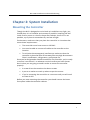
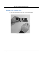
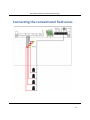
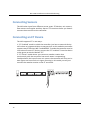
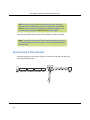
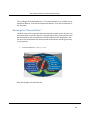
NETAFIM LANDSCAPE CONTROLLERS
NLC‐100S Installation and troubleshooting NLC-100S
INSTALLATION & TROUBLESHOOTING MANUAL
NLC-100S
1
NLC‐100S Installation and troubleshooting Copyright January 2014. All rights reserved. No part of this publication may be reproduced, stored in a retrieval system, or transmitted in any form or by any means electronic, mechanical, photocopying, recording or otherwise without the prior permission of the publisher.
Netafim USA
5470 E. Home Ave.
Fresno, CA 93727
Phone:
(888) 638‐2346
(559) 453‐6800
Fax: (559) 453‐6803
Email:
[email protected]
450-230-0004/A
2
NLC‐100S Installation and troubleshooting Table of Contents
Chapter 1: Introducing NLC‐100S............................................................................................. 5
The Controller .......................................................................................... 5
Irrigation Features .................................................................................... 5
Chapter 2: System Installation ................................................................................................. 7
Mounting the Controller ................................................................................. 7
Marking up the mounting holes ............................................................... 8
Connecting the Controller ............................................................................. 10
Grounding the Controller ....................................................................... 10
Connecting the conventional field wires ............................................................ 11
Connecting Sensors ....................................................................................... 12
Connecting an ET Device ............................................................................... 12
Using a Connected Device (Weather Station) ................................................ 13
Configuring ET Input ............................................................................... 13
Checking the Current Aggregated ET and Rain .............................................. 21
Reading current aggregated ET and Rain figures ..................................... 21
Connecting a Rain Sensor .............................................................................. 24
Configuring for a Rain Sensor ................................................................. 25
Setting Hourly Maximum Rain and Rain Alarm Level ..................................... 30
Setting the Hourly Max. Rain and Rain Alarm Level ................................ 31
Connecting a Flow Sensor ............................................................................. 34
Enabling Flow Sensor Input (pulses) .............................................................. 35
Enabling flow sensor pulse input in the NLC ........................................... 35
Configuring for Flow Sensor Input ................................................................. 36
Selecting Sensor Type ............................................................................. 37
Using a built‐in calibration profile .......................................................... 37
Setting the Flow Sensor Adjustment ....................................................... 41
Adjusting the flow sensor input .............................................................. 41
3
NLC‐100S Installation and troubleshooting Viewing the Current Flow ............................................................................. 42
Connecting an Alarm ..................................................................................... 44
Connecting a Moisture sensor ...................................................................... 45
Connecting, Configuring and Using Moisture Sensors ................................... 45
Connecting and configuring a moisture sensor ....................................... 46
Assigning an ID to a soil moisture sensor ............................................... 46
Configuring a soil moisture sensor ......................................................... 49
Chapter 3: System activation ................................................................................................. 53
Station license ........................................................................................ 53
Moisture license ..................................................................................... 55
Chapter 4: Troubleshooting from the Controller................................................................... 57
Testing Stations ............................................................................................. 57
Enabling current readings ....................................................................... 57
Running the "Electrical Test" .................................................................. 59
Special current readings from the station test ..................................61
Running the "Water Test" .............................................................................. 62
Running the test program ....................................................................... 62
Testing Programs ........................................................................................... 64
Glossary ............................................................................................................. 65
4
NLC‐100S Installation and troubleshooting Chapter 1: Introducing NLC‐100S
The NLC is a microprocessor based irrigation control system. A central controller and up to 100 field stations comprise a complete system. In addition the controller will accept input from several external sensors in order to adjust its irrigation to the local weather conditions.
The Controller
The heart of a NLC based system is the controller. This is a microprocessor controlled device that stores your irrigation programs and NLC individual stations in the field when to activate their valve(s).
Irrigation Features
Here are the main features that the NLC utilizes to help you automate your irrigation:
• Controls up to 100 solenoids attached to valves or relays via the built‐in connection board and three expansion boards.
• Provides ET corrected irrigation for optimal adjusted water consumption.
• Measures water flow and raises alarms or halts irrigation on unexpected flow.
• Allows for 10 independent irrigation programs. In addition there is a fixed test program that activates all 100 stations in turn.
• A program can activate up to 100 stations in named order.
• Each station can run for up to 17:59:50 (In fact, you can boost this even further by increasing the "water budget".
• Each program can activate a one or more booster pumps in addition to the stations.
• Master valves and booster pumps will be activated in parallel in all connection and expansion boards.
5
NLC‐100S Installation and troubleshooting • All programs have 12 start times per day.
• All programs can run simultaneously (to capacity of the transformer anc connection board).
• You configure each program to run on any selection of days in a 14 day period, or on odd/even dates.
• You can activate one or more valves or programs manually while one or more programs are running, up to a total of 12 simultaneously running valves.
• A master valve can be selected that will open when any program or station is run.You typically assign master valve status to the valve controlling access to municipal water or pumping station.
• Up to 10 moisture sensors that can monitor soil moisture and adjust irrigation accordingly.
6
NLC‐100S Installation and troubleshooting Chapter 2: System Installation
Mounting the Controller
Though the NLC is designed to resist both rain and direct sun light, you should place it in a friendlier environment if possible. Installing the NLC inside a utility room or a shed is the perfect solution, but if this is not possible, try to place it somewhere dry and out of sight.
Furthermore, make sure that you place the controller in a location that meets these requirements:
• The controller must have access to 120 VAC.
• You must be able to connect all cables to the controller at the location.
• To minimize electromagnetic interference, make sure that the controller is placed at least 15 feet away from any high‐draw motors like air conditioners, refrigerators, pool pumps etc.
Once you've designated a suitable location for the controller, you're ready to mount it on the wall ‐ or whatever vertical surface you have chosen. Here's what you are going to need in order to mount the controller properly:
• A screw driver that matches the above screws.
• A pen or a marker to mark up where to put the screws.
• If you're mounting the controller on a concrete wall you will need an electric drill.
Before you start mounting the controller you should remove the lower front plate inside the controller cabinet.
7
NLC‐100S Installation and troubleshooting Marking up the mounting holes
1 Make sure the bracket is in level. Mark up the mounting holes.
8
NLC‐100S Installation and troubleshooting 2
Use a pen to put marks on the wall through the hole in the back of the controller cabinet.
3
If you're placing the controller on a concrete wall, take down the controller, drill out the hole, put in the wall anchor, and put back the controller on the wall.
4
Fasten the screw in the wall through the holes in the back of the controller cabinet.
9
NLC‐100S Installation and troubleshooting Now the controller should be mounted firmly on the wall. After mounting the controller, it's time to connect the power and connect boards ‐ follow the instructions in the next section to do this.
Connecting the Controller
Grounding the Controller
To secure your NLC against lightning, you must ensure that the controller is grounded through a ground rod connected to the ground lugs.
Warning
You will void the warranty by not grounding your NLC properly.
10
NLC‐100S Installation and troubleshooting Connecting the conventional field wires
11
NLC‐100S Installation and troubleshooting Connecting Sensors
The NLC takes input from different sensor types: ET devices, rain sensors, flow sensors and regular auxiliary alarms. This sections shows you how to connect these sensors to the controller.
Connecting an ET Device
The NLC supports ET in two ways:
1. "ET Enabled" mode in which the controller just lets an external device tell it when to irrigate and when to stay passive. In this mode the controller supports two ET devices: WR‐7 and WR100i. To make the controller receive instructions from an ET device, connect the "ET enable A" from the device to the green terminals labeled "ET."
12
NOM
M205
BO2
M204
MV
M203
BO1
M202
ET
GND
Rain
GND
Flow
GND
V-Aux
GND
2. "ET Pulses" mode where you connect a weather station that continuously tells the controller how much water is evaporating. Combined with the input from a rain sensor the controller will then on its own figure out how much to irrigate. Running in this mode you still just connect the weather station to the ET terminals.
COM
-
COM
-
NLC‐100S Installation and troubleshooting Important! Be aware of the polarity when you connect devices to the NLC: Connect plus to plus and minus to minus or you won't see the expected behavior from the connected devices.
Using a Connected Device (Weather Station)
Connecting an ET device on‐site gives you the most accurate adjustments as the ET device will monitor the exact weather condition right where irrigation will take place.
Important! If for some reason your weather stations fails and does not provide any input for the NLC the controller will fall back on historical ET data and use these instead. The same goes in case of a power failure ‐ the controller will use the historical data for the part of today that lies before the power failure, and then use real‐time ET data from when it is powered up again. Bottom line: you should always enter a set of historical ET data even when running with a connected weather station.
Configuring ET Input
1 Before moving on, make sure you have connected the ET device. 2
Turn the dial to ADVANCED
13
NLC‐100S Installation and troubleshooting PAUSE/
RESUME
STOP
MANUAL
OFF
RAIN OFF
RAIN ALARM STATUS
VIEW ALARMS
VIEW ET & RAIN
VIEW MOISTURE SENSOR
SETUP SENSORS
AUTO
SET DATE & TIME
PROGRAM
RUN TIME
WATER DAYS
START TIME
WATER BUDGET / ET
PROGRAM STATUS
ADVANCED
SOLENOID AMPS
Now the display looks like this:
3
14
Use the item selectors to select 3. Intelliset and push the ENTER
button. Now you'll see the following screen:
NLC‐100S Installation and troubleshooting 4
Select 6. Device Setup. Now the display will look like this:
5
Select 1. ET Input Method. Now the display will look like this:
6
Use the item selectors to select Local Weather Station and push the ENTER button.
15
NLC‐100S Installation and troubleshooting 7
Select 3. ET Base Setup from the menu and push the ENTER
button. Now you'll see the following screen:
Note: See the NLC 100 User Manual for more information about Base ET.
8
For each program, use the item selectors to determine how many inches of water the program will provide when running at a 100% water budget. The controller needs this in order to re‐calculate run times based on ET corrections.
Push the ENTER button to save the value.
9
Push the CANCEL button once to return to the main Intelliset™
menu.
10 Use the item selectors to select 2. ET Limits (Min and Max) and push the ENTER button. Now you'll see the following screen:
16
NLC‐100S Installation and troubleshooting 11 Now use the item selectors to determine the two values and push ENTER to save your settings: • Minimum ET: The ET figure must exceed this value in order for the controller to irrigate at all.
• Maximum ET: If the ET balance for a program exceeds this value, the program will only irrigate to that limit, and the remaining water will be added to the ET figure for the following day.
12 Turn the dial to SETUP SENSORS:
PAUSE/
RESUME
STOP
MANUAL
OFF
RAIN OFF
RAIN ALARM STATUS
VIEW ALARMS
VIEW ET & RAIN
VIEW MOISTURE SENSOR
SETUP SENSORS
AUTO
SET DATE & TIME
PROGRAM
RUN TIME
WATER DAYS
START TIME
WATER BUDGET / ET
PROGRAM STATUS
ADVANCED
SOLENOID AMPS
Now the display looks like this:
17
NLC‐100S Installation and troubleshooting 13 Use the item selectors to select 1. ET and push the ENTER button.
Now the display looks like this:
14 Now you can choose between four settings:
ET device (Pulses)
Select this if you use a connected ET device that provides dynamic ET data for the controller (ET 300‐w)
ET enabled (N/O or N/C)
18
NLC‐100S Installation and troubleshooting If your ET device simply tells the controller whether to irrigate or not, you need to tell the controller if the input is normally open (N/O) or normally closed (N/C). Whenever the device is then in the opposite mode, the controller will hold its irrigation. This is typically a WR7 Receiver.
Disabled
Don't use the ET input.
Use the item selectors to locate the setting you want and if you chose anything but ET device (Pulses), push the ENTER button to save your selection and the SENSORS button to exit sensor configuration.
If you chose ET device (Pulses), you need to tell the controller how many inches to the current ET figure per pulse it receives ‐ please proceed to the next step (default setting is 0.01".)
15 Turn the dial to ADVANCED
PAUSE/
RESUME
STOP
MANUAL
OFF
RAIN OFF
RAIN ALARM STATUS
VIEW ALARMS
VIEW ET & RAIN
VIEW MOISTURE SENSOR
SETUP SENSORS
AUTO
SET DATE & TIME
PROGRAM
RUN TIME
WATER DAYS
START TIME
WATER BUDGET / ET
PROGRAM STATUS
ADVANCED
SOLENOID AMPS
Now the display looks like this:
19
NLC‐100S Installation and troubleshooting 16 Use the item selectors to select 3. Intelliset and push the ENTER
button. Now you'll see the following screen:
17 Select 6. Device Setup. Now the display will look like this:
20
NLC‐100S Installation and troubleshooting 18 Select 2. ET and Rain Inch/Pulse Settings. Now you'll see something like this:
19 Use the item selectors to set your values and push the ENTER button to save your settings.
Checking the Current Aggregated ET and Rain
Every now and then you might want to check out how much rain has fallen or how much water has evaporated ‐ the NLC has a screen that shows you the accumulated values in real time:
Reading current aggregated ET and Rain figures
1 Turn the dial to ADVANCED
21
NLC‐100S Installation and troubleshooting PAUSE/
RESUME
STOP
MANUAL
OFF
RAIN OFF
RAIN ALARM STATUS
VIEW ALARMS
VIEW ET & RAIN
VIEW MOISTURE SENSOR
SETUP SENSORS
AUTO
SET DATE & TIME
PROGRAM
RUN TIME
WATER DAYS
START TIME
WATER BUDGET / ET
PROGRAM STATUS
ADVANCED
SOLENOID AMPS
Now the display looks like this:
2
22
Use the item selectors to select 3. Intelliset and push the ENTER
button. Now you'll see the following screen:
NLC‐100S Installation and troubleshooting 3
Select 1. Current Accumulated ET and Rain from the menu and push the ENTER button. Now you'll see the following screen:
These figures will be reset at midnight when they'll be used to calculate tomorrow's ET budget.
Note: If you use a custom irrigation period, this happens at the start of your irrigation period, which might not be midnight. See more in the NCL User Manual.
23
NLC‐100S Installation and troubleshooting Tip:If you are running in AUTO mode and want to check the current accumulated values, you can simply push the WATER BUDGET button and you'll skip right to the above display. You exit back by pushing the WATER BUDGET button again.
This way you don't have to exit AUTO mode to check the values.
Note: To make sure that the ET device works properly, you have to wait for the device to return pulses. This will typically happen the next day.
Connecting a Rain Sensor
24
NOM
M205
BO2
M204
MV
M203
BO1
M202
ET
GND
Rain
GND
Flow
GND
V-Aux
GND
You can connect a rain sensor (pulse or switch) to the NLC via the grey terminals labeled "Rain":
COM
-
COM
-
NLC‐100S Installation and troubleshooting Important! Be aware of the polarity when you connect devices to the NLC: Connect plus to plus and minus to minus or you won't see the expected behavior from the connected devices.
The NLC can accept input from an external rain sensor or a tipping rain bucket, and react in three ways:
• Simply stop irrigating if it rains at all (works with sensors and tipping rain bucket.)
• Stop irrigating if the rain level exceeds a certain threshold (works with sensors and tipping rain bucket.)
• Adjust irrigation based on the amount of rain (only works with a ripping rain bucket.)
Note: In a master/slave setup you do not need a rain sensor connected to all slaves ‐ the master can simply send out alarms to all slaves instead.
The following procedure walks you through configuring the controller for rain sensor input ‐ it is identical to parts of the procedure for ET.
Configuring for a Rain Sensor
1 Before moving on, make sure you have connected the rain sensor. For more information refer to the separate Installation and Troubleshooting manual.
2
Turn the dial to SETUP SENSORS:
25
NLC‐100S Installation and troubleshooting PAUSE/
RESUME
STOP
MANUAL
OFF
RAIN OFF
RAIN ALARM STATUS
VIEW ALARMS
VIEW ET & RAIN
VIEW MOISTURE SENSOR
SETUP SENSORS
AUTO
SET DATE & TIME
PROGRAM
RUN TIME
WATER DAYS
START TIME
WATER BUDGET / ET
PROGRAM STATUS
ADVANCED
SOLENOID AMPS
Now the display looks like this:
3
Use the item selectors to select 2. Rain and push the ENTER
button.
Now the display looks like this:
26
NLC‐100S Installation and troubleshooting 4
Now you can choose between three settings:
Rain gauge (Pulses)
If your rain sensor provides dynamic data in the sense that it sends a pulse for each unit of rain it detects, select Pulses.
Rain contact (N/O or N/C)
If your rain sensor simply tells the controller whether to irrigate or not (if it's raining or not), you need to tell the controller if the input is normally open or closed. Whenever the device is in the opposite mode, the controller will not irrigate.
Disabled
Don't use the Rain input.
Use the item selectors to locate the setting you want and if you chose anything but Rain gauge (Pulses), push the ENTER button to save your selection and the SENSORS button to exit sensor configuration.
If you do chose Rain gauge (Pulses), you need to tell the controller how many inches of rain each pulse corresponds, so please continue to the next step.
27
NLC‐100S Installation and troubleshooting Important! If you want to receive remote rain data from an ET server, you must disable your local rain sensors.
5
Turn the dial to ADVANCED
PAUSE/
RESUME
STOP
MANUAL
OFF
RAIN OFF
RAIN ALARM STATUS
VIEW ALARMS
VIEW ET & RAIN
VIEW MOISTURE SENSOR
SETUP SENSORS
AUTO
SET DATE & TIME
PROGRAM
RUN TIME
WATER DAYS
START TIME
WATER BUDGET / ET
PROGRAM STATUS
ADVANCED
SOLENOID AMPS
Now the display looks like this:
6
28
Use the item selectors to select 3. Intelliset and push the ENTER
button. Now you'll see the following screen:
NLC‐100S Installation and troubleshooting 7
Select 6. Device Setup. Now the display will look like this:
8
Select 2. ET/Rain Setup and then 2. ET and Rain Inch/Pulse
settings. Now you'll see something like this:
29
NLC‐100S Installation and troubleshooting 9
Use the item selectors to set your values and push the ENTER button to save your settings.
Setting Hourly Maximum Rain and Rain Alarm Level
The NLC allows for two precautions when you experience rain:
You can set a threshold value for how much it should rain before the rain alarm will be activated. Here is how this calculation is done:
• Based on historical ET data for the area, the controller knows how much water is evaporating per day during the current season.
• The NLC assumes that 75% of the daily ET is evaporating between 8AM and 8PM, and the remaining 25% between 8PM and 8AM.
• When the amount of rain exceeds the rain alarm level you define, the rain alarm is activated.
• Now, based on the historical ET data the controller will calculate how much rain will evaporate, and mapping this number against the known amount of fallen rain, the controller will intelligently know when it is safe to turn off the rain alarm (i.e. when enough rain has evaporated that we are below your defined alarm level.)
• The soil holding value is also a parameter: since you can never benefit from more rain than the soil is capable of holding, the rain alarm will not stay on forever after a few days of intensive rain.
Note: If you have not provided any historical ET, a default of 0.20" per day is used. See more in the NCL User Manual.
30
NLC‐100S Installation and troubleshooting • If it rains intensively for more than an hour you may get so much water that the soil can not benefit from all of it ‐ the excess water will simply run off the surface. So if you run programs in ET corrected mode, the controller won't subtract all of the rain from tomorrow's ET figure ‐ it will "cut off" the amount of rain to subtract at the hourly maximum. Example: If the hourly maximum is 0.02" and it rains 0.03" per hour for three hours, only 0.06" and not 0.09" will be subtracted from tomorrow's ET budget.
See more in the NCL User Manual.
Setting the Hourly Max. Rain and Rain Alarm Level
1 Turn the dial to ADVANCED
PAUSE/
RESUME
STOP
MANUAL
OFF
RAIN OFF
RAIN ALARM STATUS
VIEW ALARMS
VIEW ET & RAIN
VIEW MOISTURE SENSOR
SETUP SENSORS
AUTO
SET DATE & TIME
PROGRAM
RUN TIME
WATER DAYS
START TIME
WATER BUDGET / ET
PROGRAM STATUS
ADVANCED
SOLENOID AMPS
Now the display looks like this:
31
NLC‐100S Installation and troubleshooting 32
2
Use the item selectors to select 3. Intelliset and push the ENTER
button. Now you'll see the following screen:
3
Select 1. ET. Now the display will look like this:
NLC‐100S Installation and troubleshooting 4
Select 3. Max Hourly Rain and Rain Alarm Limit from the menu and push the ENTER button. Now you'll see the following screen:
Note: Setting a value to zero is the same as disabling the feature.
Note: If you see "NA" values in this screen you have not configured a rain sensor to provide input using pulses. For more information turn to Capter 2: Configuring for a Rain Sensor on page 25.
Note: Be aware that testing the tipping rain bucket input by flipping the "spoon" will accumulate "rain" in the controller. Do it with caution as it can't be deleted by cycling the power.
Use the item selectors to set the desired values and push the ENTER button to save your settings.
33
NLC‐100S Installation and troubleshooting Connecting a Flow Sensor
A traditional flow sensor is connected to the "Flow" terminals.
)
A photo diode type flow sensor is also connected to the “Flow” terminal, and via the “V‐Aux” terminal through a resistor.
Recommended resistor values:
• 9V: 330 Ohm, 0.25 Watt
• 12V: 470 Ohm, 0.5 Watt
34
NLC‐100S Installation and troubleshooting Enabling Flow Sensor Input (pulses)
By default flow sensor input is enabled in the NLC. To enable flow sensor input to accept pulses, follow this procedure:
Note: You can enable flow sensor input even if you haven't attached a physical sensor yet ‐ you just won't get any reading from it.
Enabling flow sensor pulse input in the NLC
1 Turn the dial to SETUP SENSORS:
PAUSE/
RESUME
STOP
MANUAL
OFF
RAIN OFF
RAIN ALARM STATUS
VIEW ALARMS
VIEW ET & RAIN
VIEW MOISTURE SENSOR
SETUP SENSORS
AUTO
SET DATE & TIME
PROGRAM
RUN TIME
WATER DAYS
START TIME
WATER BUDGET / ET
PROGRAM STATUS
ADVANCED
SOLENOID AMPS
Now the display looks like this:
35
NLC‐100S Installation and troubleshooting 2
Use the item selectors to select item number 3. Alarm/Flow and you'll see the default setting for sensor setup, Flow (Pulses):
3
Push the ENTER button to save your selection.
Now the NLC is ready to accept input from your flow sensor, but before you can use it to anything meaningful you need to configure threshold values and actions ‐ read more in the next section.
Configuring for Flow Sensor Input
In the previous section you enabled the NLC to accept flow sensor input ‐ now you need to configure what to do with it and this section walks you through the relevant procedures.
36
NLC‐100S Installation and troubleshooting Selecting Sensor Type
By telling the NLC which type of sensor you are using, the controller can calibrate the input it receives from the input terminals. The NLC knows the calibration profiles for 12 different sensor types ‐ if you're not using one of these you'll have to skip to the next procedure to perform a manual calibration for your sensor.
Using a known sensor type to enable a built‐in profile:
Using a built‐in calibration profile
1 Turn the dial to ADVANCED, use the item selectors to scroll to item number 3. FloGuard, and push the ENTER button.
Now you'll see this display:
2
Select 4. Flow Sensor Setup, and push the ENTER button.
Now you'll see this display:
37
NLC‐100S Installation and troubleshooting 3
Choose 1. Flow Sensor Type by pushing the ENTER button.
Now you'll see this display:
38
4
Use the item selectors to select one of the 13 built‐in profiles:
•
1" RS
•
1" PDH
•
1.5" RS
•
1.5" PDH
•
2" RS
•
2" PDH
•
3" RS
•
3" PDH
NLC‐100S Installation and troubleshooting •
4" RS
•
4" PDH
•
6" RS
•
6" PDH
• "Custom"
5
Push the ENTER button to save your selection.
If your sensor doesn't fit any of the built-in profiles you have to enter your own manually:
Using a custom calibration profile
1 Turn the dial to ADVANCED, use the item selectors to scroll to item number 3. FloGuard, and push the ENTER button.
Now you'll see this display:
2
Select 4. Flow Sensor Setup, and push the ENTER button.
Now you'll see this display:
39
NLC‐100S Installation and troubleshooting 3
Use the item selectors to locate the Custom option and select it by pressing the ENTER button. Now you'll see the calibration screen:
Note: A bit of background on how calibration affects the calculated flow: The NLC needs to know the "K" and "Offset" values of your sensor (K‐factor and offset are the parameters of the flow meter known from the datasheet), as the actual flow will be calculated from this formula:
ActualFlow = K * (Pulses + Offset)
About the two values you need to enter:
• The "Offset" value is to correct the input from your sensor.
40
NLC‐100S Installation and troubleshooting •
• The "K" value can be looked up in the data sheet for your sensor.
4
Use the item selectors to enter your values and push the ENTER
button to save your settings.
Setting the Flow Sensor Adjustment
If you want to calibrate your flow sensor, you can use the sensor adjustment to multiply the values from your sensor with anything between 0.00 and 9.99.
This comes in handy if you have a standard sensor that behaves slightly different than the built‐in profile calculates.
Adjusting the flow sensor input
1 Turn the dial to ADVANCED, use the item selectors to scroll to item number 3. FloGuard, and push the ENTER button.
Now you'll see this display:
41
NLC‐100S Installation and troubleshooting 2
Select 4. Flow Sensor Setup, and push the ENTER button.
Now you'll see this display:
3
Choose 2. Flow Sensor Adjustment. Now you'll see the screen for adjusting the flow sensor input:
4
Use the item selectors to set your adjustment factor.
Push the ENTER button to save your selection.
Viewing the Current Flow
Given that you have configured your flow sensor correctly, the NLC lets you see the real time flow directly in the controller display:
42
NLC‐100S Installation and troubleshooting 1 Turn the dial to ADVANCED, use the item selectors to scroll to item number 3. FloGuard, and push the ENTER button.
Now you'll see this display:
2
Select 4. Flow Sensor Setup, and push the ENTER button.
Now you'll see this display:
3
Select 3. Current Flow Pulses and GPM and you'll see the current system flow in both pulses per second and gallons per minute:
43
NLC‐100S Installation and troubleshooting Note: The NLC can measure correctly up to a flow of 250 pulses per second. If your flow exceeds this you should use a sensor that has a higher "water amount per pulse" ratio. However, a higher frequency is to prefer over a lower one, as it provides the most accurate measuring, so in an ideal world your frequency closes in on 250 pulses per second without ever exceeding it. For more information turn to Capter 2: Selecting Sensor Type on page 37.
Connecting an Alarm
44
NOM
M205
BO2
M204
MV
M203
BO1
M202
ET
GND
Rain
GND
Flow
GND
V-Aux
GND
The grey terminals labeled "AUX" are intended for a regular auxiliary alarm.
COM
-
COM
-
NLC‐100S Installation and troubleshooting Note: An alarm is used instead of a Flow Sensor. Turn the dial to SENSOR SETUP and select N/O eller N/C. Connecting a Moisture sensor
Connecting, Configuring and Using Moisture Sensors
This section describes how you actually get the moisture sensors ready for use and how they can improve your irrigation.
Note: The SMS are pre‐programmed, so programming is not necessary.
The NLC works with the following moisture sensors:
• SMS‐100 (single sensor)
45
NLC‐100S Installation and troubleshooting Connecting and configuring a moisture sensor
Before you can enjoy the benefits of moisture sensor input you must connect it to the moisture sensor wire, obtain a license from your distributor and perform some basic configuration.
Follow this procedure to get your moisture sensor up and running:
Note: You must have entered a license key for the controller before you are able to configure moisture sensors. Assigning an ID to a soil moisture sensor
1 Connect the soil moisture sensor to the RS232 port on the controller via an SMI‐100 interface. 2
Turn the dial to ADVANCED
PAUSE/
RESUME
STOP
MANUAL
OFF
RAIN OFF
RAIN ALARM STATUS
VIEW ALARMS
VIEW ET & RAIN
VIEW MOISTURE SENSOR
SETUP SENSORS
SOLENOID AMPS
Now the display looks like this:
46
AUTO
SET DATE & TIME
PROGRAM
RUN TIME
WATER DAYS
START TIME
WATER BUDGET / ET
PROGRAM STATUS
ADVANCED
NLC‐100S Installation and troubleshooting 3
Use the item selectors to select 3. Intelliset and push the ENTER
button. Now you'll see the following screen:
4
Select 4. Moisture Sensor Id Assign and push the ENTER button.
Now the display looks like this:
47
NLC‐100S Installation and troubleshooting 5
Select 4. Moisture Sensor Id Assign and push the ENTER button. Now
the display looks like this:
The number of sensors available in the list depends on your license.
6
Use the item selectors to choose the ID you wish to assign to the newly connected moisture sensor and push the ENTER button.
Now the controller will first check that there are no existing moisture sensors with the
ID you chose:
If no clashes in ID numbers are found, the controller moves on to detect the new
sensor:
48
NLC‐100S Installation and troubleshooting If all goes well you will see the following message in the display:
Once your moisture sensor has an ID you need to tell the controller what type of
sensor it is and in which type of soil it is placed.
Follow this procedure to make the sensor known to the NLC:
Configuring a soil moisture sensor
1 Turn the dial to ADVANCED
49
NLC‐100S Installation and troubleshooting PAUSE/
RESUME
STOP
MANUAL
OFF
RAIN OFF
RAIN ALARM STATUS
VIEW ALARMS
VIEW ET & RAIN
VIEW MOISTURE SENSOR
SETUP SENSORS
AUTO
SET DATE & TIME
PROGRAM
RUN TIME
WATER DAYS
START TIME
WATER BUDGET / ET
PROGRAM STATUS
ADVANCED
SOLENOID AMPS
Now the display looks like this:
2
50
Use the item selectors to select 3. Intelliset and push the ENTER
button. Now you'll see the following screen:
NLC‐100S Installation and troubleshooting 3
Select 2. Moisture and push the ENTER button. Now the display looks
like this:
4
Select 2. Moisture Sensor Setup and push the ENTER button. Now
the display looks like this:
5
Use the item selectors to select the ID of the sensor you wish to configure (You assigned the ID in the previous procedure: For more 51
NLC‐100S Installation and troubleshooting information turn to Capter 2: Assigning an ID to a soil moisture sensor on page 46 and then adjust each column:
Column
Description
Whether the moisture sensor should be enabled or not.
Enable
The type of sensor associated with the ID. Supported sensors are:
• SMS‐100
Type
Soil type
The type of soil in which the sensor is placed. Options are:
• Clay
• Sand
• Loam
• Standard
6
Push the ENTER button to save your configuration.
7
Repeat steps five and six for all sensors you wish to configure.
Now the moisture sensors are ready to use, and the next sections go into detail on how you assign them to control your irrigation schedules.
52
NLC‐100S Installation and troubleshooting Chapter 3: System activation
The default license that ships with your controller allows for only one station. Note: The NLC comes predefined with the station license you have purchased. Further licenses are only needed if the system is expanded or moisture sensors are added.
Most likely you have purchased a license that allows for more stations, and to unlock the NLC to control all your licensed stations, follow this procedure:
Station license
1 Turn the dial to Advanced
PAUSE/
RESUME
STOP
MANUAL
OFF
RAIN OFF
RAIN ALARM STATUS
VIEW ALARMS
VIEW ET & RAIN
VIEW MOISTURE SENSOR
SETUP SENSORS
AUTO
SET DATE & TIME
PROGRAM
RUN TIME
WATER DAYS
START TIME
WATER BUDGET / ET
PROGRAM STATUS
ADVANCED
SOLENOID AMPS
53
NLC‐100S Installation and troubleshooting The display looks like this:
ENTER
YES
2
Press the arrow key down to 9. License, and you will see a display like this (your ID will be different):
Note
To obtain a license key for more stations you need to know the ID you see in this display ‐ keep this ready when ordering.
54
NLC‐100S Installation and troubleshooting 3
Press the ENTER button once and the first license key character starts blinking. Now you can use arrow keys to select the right characters and the right arrow to move on to the next character. If your license code is correct, you will see a message like the following:
In this case the license is valid for 36 stations.
Your new license will take effect immediately and you can start building irrigation programs with all your licensed stations right away. 4
After pressing any key to continue you will be back at this display:
Moisture license
5
Repeat 1 og 2. If you have a license for moisture sensors, push the up arrow key to locate the line for moisture sensor license code:
55
NLC‐100S Installation and troubleshooting Press the ENTER button once and the first license key character starts blinking. Now you can use arrow keys to select the right characters and the right arrow to move on to the next character.
If your license code is correct, you will see a message like the following:
In this case the license is valid for three moisture sensors.
56
NLC‐100S Installation and troubleshooting Chapter 4: Troubleshooting from the Controller
Testing Stations
This section describes the various ways you can troubleshoot your controller and stations.
Enabling current readings
The most important tool in day to day troubleshooting is the built‐in current readings. To enable current readings in the display of the NLC, follow this procedure:
1 Turn the dial to ADVANCED
PAUSE/
RESUME
STOP
MANUAL
OFF
RAIN OFF
RAIN ALARM STATUS
VIEW ALARMS
VIEW ET & RAIN
VIEW MOISTURE SENSOR
SETUP SENSORS
AUTO
SET DATE & TIME
PROGRAM
RUN TIME
WATER DAYS
START TIME
WATER BUDGET / ET
PROGRAM STATUS
ADVANCED
SOLENOID AMPS
Now the display looks like this:
57
NLC‐100S Installation and troubleshooting 2
Select 8. Enable/Disable line mA display and push the ENTER
button.
3
Use the item selectors to select Enable and push the ENTER again.
When you return to either AUTO or MANUAL mode, you'll see the line status in the upper right hand corner:
Note
The display will return to showing the time if you power down the controller.
The current reading will toggle between current readings for the internal connection board and any expansion boards you may have connected.
58
NLC‐100S Installation and troubleshooting The reading will be prefixed with 'I' for Internal board, or a number for an expansion board: '1' for the first expansion board, '2' for the second and '3' for the third.
Running the "Electrical Test"
The NLC has a built‐in test that will activate each station in turn for just one second in order to check if they are responding correctly. The stations must be connected to the solenoids that activate valves in the landscape, and the test can tell whether the stations and solenoids are working correctly in conjunction.
1 Turn the dial to SOLENOID AMPS:
PAUSE/
RESUME
STOP
MANUAL
AUTO
OFF
RAIN OFF
RAIN ALARM STATUS
VIEW ALARMS
VIEW ET & RAIN
VIEW MOISTURE SENSOR
SETUP SENSORS
SET DATE & TIME
PROGRAM
RUN TIME
WATER DAYS
START TIME
WATER BUDGET / ET
PROGRAM STATUS
ADVANCED
SOLENOID AMPS
Now the display will look like this:
59
NLC‐100S Installation and troubleshooting 2
Use the item selectors to select a station and push the ENTER button to start the test.
If the station is ok, the display will look something like this:
In this case the station is pulling a current of 238mA to keep the valve open, which is ok since this is typically in the 200‐400 mA range.
Note: The number before the slash is the current on the wire before trying to activate the station ‐ if this is much more than zero, there could be a leak somewhere.
60
NLC‐100S Installation and troubleshooting If the station fails, the display will look something like this:
If the station is not working correctly it is typically not pulling any current at all ‐ the current reading is 0 mA.
Note
Note: There are a few special readings that you should be aware of:
Special current readings from the station test
Reading
-1mA / -1mA
Meaning
There is a short on the terminal (on the controller) Important
If you experience a short on the terminal and fix it, you must restart the electrical test, or all following stations will appear to have a terminal short.
-2mA / -2mA
There is a situation of overload (more than 2A for more than five minutes.)
-3mA / -3mA
There is a blown fuse on the connect board.
61
NLC‐100S Installation and troubleshooting Regardless of whether the station fails or turns out ok, you move on to testing the next station in line by pushing the ENTER button.
Running the "Water Test"
The "water test" is a built‐in program that will activate all 100 station identities in the system in turn. This way you can walk through the landscape and ensure that all stations are actually pulling the valves open.
Running the test program
1 Turn the dial to MANUAL:
PAUSE/
RESUME
STOP
MANUAL
OFF
RAIN OFF
RAIN ALARM STATUS
VIEW ALARMS
VIEW ET & RAIN
VIEW MOISTURE SENSOR
SETUP SENSORS
AUTO
SET DATE & TIME
PROGRAM
RUN TIME
WATER DAYS
START TIME
WATER BUDGET / ET
PROGRAM STATUS
ADVANCED
SOLENOID AMPS
2
Push the PROGRAM button, locate the "Test" program (called "T") and push the ENTER
3
Now you can set the time each valve should be pulled open, and which station you wish to start from.
The interval must be between 10 and 990 seconds.
62
NLC‐100S Installation and troubleshooting Once you've set the interval time, push the ENTER button to start the test program. 4
Once the test program starts running, you'll see each station activated in turn, starting at the station you chose in the last step:
Note: All 100 station identities will activate in turn ‐ this means that if you don't have connected stations to all slots in the connection boards, you will experience "empty" intervals where no stations react to the instructions.
63
NLC‐100S Installation and troubleshooting Note: The test will include the Master Valve but not Booster Pumps.
Tip: You can pause the test program just as any regular program. Tip: You should enable Line Survey to be able to see the current pulled by each station.
Testing Programs
The easiest way to test whether a program is running correctly ‐ that is, it activates the correct stations,master valves and booster pump relays ‐ is to try to run the program manually. Tip: If you don't want to wait the entire program out just to see that everything activates in the right order, you can decrease the water budget to 1 percent before running the program. This way you can "follow" the program by walking from station to station in the terrain as they activate for just one percent of the original run time.
64
NLC‐100S Installation and troubleshooting Glossary
Term
Description
Cable
Two wires surrounded by insulation.
Two‐wire
Synonym for a cable.
Wire
An individual copper wire.
65
NLC‐100S Installation and troubleshooting 66
NLC‐100SH Installation and troubleshooting 67
NLC‐100SH Installation and troubleshooting NETAFIM USA
68
5470 E. Home Ave.
Fresno, CA 93727
CS 888 638 2346
www.netafimusa.com