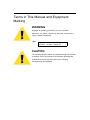
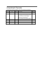
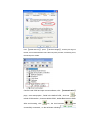
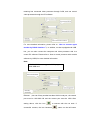
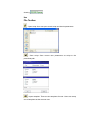
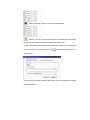
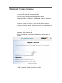
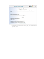
1
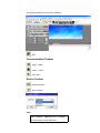
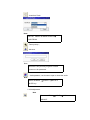
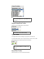
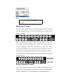
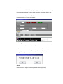
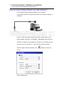
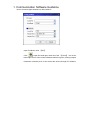
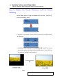
LX495 DIGITAL VIDEO PROCESSOR WITH SENDING CARD USER MANUAL Operators Safety Summary The general safety information in this summary is for operating personnel. Do Not Remove Covers or Panels There are no user-serviceable parts within the unit. Removal of the top cover will expose dangerous voltages. To avoid personal injury, do not remove the top cover. Do not operate the unit without the cover installed. Power Source This product is intended to operate from a power source that will not apply more than 230 volts rms between the supply conductors or between both supply conductor and ground. A protective ground connection by way of grounding conductor in the power cord is essential for safe operation. Grounding the Product This product is grounded through the grounding conductor of the power cord. To avoid electrical shock, plug the power cord into a properly wired receptacle before connecting to the product input or output terminals. A protective-ground connection by way of the grounding conductor in the power cord is essential for safe operation. Use the Proper Power Cord Use only the power cord and connector specified for your product. Use only a power cord that is in good condition. Refer cord and connector changes to qualified service personnel. Use the Proper Fuse To avoid fire hazard, use only the fuse having identical type, voltage rating, and current rating characteristics. Refer fuse replacement to qualified service personnel. Do Not Operate in Explosive Atmospheres To avoid explosion, do not operate this product in an explosive atmosphere. Terms in This Manual and Equipment Marking WARNING Highlight an operating procedure, practice, condition, statement, etc, which, if not strictly observed, could result in injury or death of personnel. Note Highlights an essential operating procedure, condition or statement. CAUTION The exclamation point within an equilateral triangle is intended to alert the user to the presence of important operating and maintenance (servicing) instructions in the literature accompanying the appliance. Amendment Records The table below lists the changes to the Video Processor User Manual. Format Time ECO# Description Principal V1.0 2013-02-07 0000# Release BIN V1.1 2013-03-25 0001# 1. Menu update; 2. Change the Front and Rear Panel; 3. Add ―How to Connect Upper Vira Monitor by LAN Interface?‖; 4. Add ―Mainboard Program Update‖. 1. Brief Introduction This chapter is designed to introduce you to the VSP 516S User Manual. Areas to be covered are: Chapter Structure How to Use The Manual Terms and Definitions System Overview Application Questions 1. Brief Introduction Chapter Structure Chapter Structure The following chapters provide instructions for all aspects of VSP 516S operations. Chapter 1 Brief Introduction Chapter 2 Hardware Orientation Chapter 3 Hardware Installation Chapter 4 Menu Orientation Chapter 5 Communication Software Guideline Chapter 6 System Setup and Operations Chapter 7 Common Questions and Solution Appendix A Specification Appendix B Contact Information Appendix C Software Upgrade 1. Brief Introduction How to Use This Guide How to Use the Manual Followings are important tips for streamlining your use of this User’s Manual in its electronic ―PDF‖ form. Navigation Use Acrobat Reader’s ―bookmarks‖ to navigate to the desired location. All chapter files have the same bookmark structure for instant navigation to any section. Please note: Extensive hyperlinks are provided within the chapters. Use Acrobat’s ―Go to Previous View‖ and ―Return to next View‖ buttons to trace your complete navigational path. Use the ―Previous Page‖ and ―Next Page‖ buttons to go to the previous or next page within a file. Use Acrobat’s extensive search capabilities, such as the ―Find‖ tool and ―Search Index‖ tool to perform comprehensive searches as required. Table of Contents and Index Use the Table of Contents bookmarks to navigate a desired topic. Click any item to instantly jump to that section of the guide. You can also use the Index to jump to specific topics within a chapter. Each page number in the Index is a hyperlink. General Operations To ensure trouble-free operation, please follow all procedures as listed below: For detailed installation instructions, refer to chapter 3 ―Hardware Installation‖ on page 36. For communication software control guide, refer to Chapter 5, ―Communication Software Control Guide‖ on page 48. For system setup and operations, refer to Chapter 6, ―System Setup and Operations‖ on page 79. 1. Brief Introduction Terms and Definitions Term and Definitions The following terms and definitions are used throughout this guide. “ASCII”: American Standard for Information Interchange. The standard code consisting of 7-bit coded characters (8 bits including parity check) used to exchange information between data processing systems, data communication systems, and associated equipment. The ASCII set contains control characters and graphic characters. “Aspect ratio”: The relationship of the horizontal dimension to the vertical dimension of an image. In viewing screens, standard TV is 4:3, or 1.33:1; HDTV is 16:9, or 1.78:1. Sometimes the ―:1‖ is implicit, making TV = 1.33 and HDTV = 1.78. “AV”: Audio visual or audio video. A “Background” is an unscaled source, typically originating from a computer. A background source appears at the system’s lowest priority — visually in back of all other sources. “Baudrate”:Named of J.M.E. Baudot, the inventor of the Baudot telegraph code. The number of the electrical oscillations per second, called baud rate. Related to, but not the same as, transfer rate in bits per second (bps). “Blackburst”: The video waveform without the video elements. It includes the vertical sync, horizontal sync, and the chroma burst information. Blackburst is used to synchronize video equipment to align the video output. One signal is normally used to set up an entire video system or facility. Sometimes it is called House sync. “BNC”: Bayonet Neill-Concelman. A cable connector used extensively in television and named for its inventors. A cylindrical bayonet connector that operates with a twist-locking motion. To make the connection, align the two curved grooves in the collar of the male connector with the two projections on the outside of the female collar, push, and twist. This allows the connector to lock into place without tools. “Brightness”: Usually refers to the amount or intensity of video light produced on a screen without regard to color. Sometimes called ―black level. ―CAT 5‖: Category 5. Describes the network cabling standard that consists of four unshielded twisted pairs of copper wire terminated by RJ-45 connectors. CAT 5 cabling supports data rates up to 100 Mbps. CAT 5 is based on the EIA/TIA 568 Commercial Building Telecommunications Wiring Standard. “Color bars”: A standard test pattern of several basic colors (white, yellow, cyan, green, magenta, red, blue, and black) as a reference for system alignment and testing. In NTSC video, the most commonly 1. Brief Introduction Terms and Definitions Used color bars are the SMPTE standard color bars. In PAL video, the most commonly used color bars are eight full field bars. In the computer, the most commonly used color bars are two rows of reversed color bars. “Color burst”: In color TV systems, a burst of sub carrier frequency located on the back porch of the composite video signal. This serves as a color synchronizing signal to establish a frequency and phase reference for the chroma signal. Color burst is 3.58 MHz for NTSC and 4.43 MHz for PAL. “Color temperature”: The color quality, expressed in degrees Kelvin (K), of a light source. The higher the color temperature, the bluer the light. The lower the temperature, the redder the light. Benchmark color temperature for the A/V industry includes 5000°K, 6500°K, and 9000°K. “Contrast ratio”: The radio of the high light output level divided by the low light output level. In theory, the contrast radio of the television system should be at least 100:1, if not 300:1. In reality, there are several limitations. In the CRT, light from adjacent elements contaminate the area of each element. Room ambient light will contaminate the light emitted from the CRT. Well-controlled viewing conditions should yield a practical contrast ratio of 30:1 to 50:1. “DVI”: Digital Visual Interface. The digital video connectivity standard that was developed by DDWG (Digital Display Work Group). This connection standard offers two different connectors: one with 24 pins that handles digital video signals only, and one with 29 pins that handles both digital and analog video. “EDID”: Extended Display Identification Data – EDID is a data structure used to communicate video display information, including native resolution and vertical interval refresh rate requirements, to a source device. The source device will then output the optimal video format for the display based on the provided EDID data, ensuring proper video image quality. This communication takes place over the DDC – Display Data Channel. “Ethernet”: A Local Area Network (LAN) standard officially known as IEEE 802.3. Ethernet and other LAN technologies are used for interconnecting computers, printers, workstations, terminals, servers, etc. within the same building or campus. Ethernet operates over twisted pair and over coaxial cable at speeds starting at 10Mbps. For LAN interconnectivity, Ethernet is physical link and data link protocol reflecting the two lowest layers of the OSI Reference Model. “Frame”: In interlaced video, a frame is one complete picture. A video frame is made up of two fields, or two sets of interlaced lines. In a film, a frame is one still picture of a series that makes up a motion picture. 1. Brief Introduction Terms and Definitions “Gamma”: The light output of a CRT is not linear with respect to the voltage input. The difference between what you should have and what is actually output is known as gamma. “HDMI” - High – Definition Multimedia Interface: An interface used primarily in consumer electronics for the transmission of uncompressed high definition video, up to 8 channels of audio, and control signals, over a single cable. HDMI is the de facto standard for HDTV displays, Blu-ray Disc players, and other HDTV electronics. Introduced in 2003, the HDMI specification has gone through several revisions. “HDSDI”: The high-definition version of SDI specified in SMPTE-292M. This signal standard transmits audio and video with 10 bit depth and 4:2:2 color quantization over a single coaxial cable with a data rate of 1.485 Gbit/second. Multiple video resolutions exist including progressive 1280x720 and interlaced 1920x1080 resolutions. Up to 32 audio signals are carried in the ancillary data. “JPEG” (Joint photographic Expects Group): Commonly used method of loss compression for photographic images using a discreet cosine transfer function. The degree of compression can be adjusted, allowing a selectable tradeoff between storage size and image quality. JPEG typically achieves 10:1 compression with little perceptible loss in image quality. Produces blocking artifacts. “MPEG”: Motion Picture Expect Group. A standard committee under the auspices of the International Standards Organization working on algorithm standards that allows digital compression, storage and transmission of moving image information such as motion video, CD-quality audio, and control data at CD-ROM bandwidth. The MPEG algorithm provides inter-frame compression of video images and can have an effective compression rate of 100:1 to 200:1. “NTSC”: The color video standard used in North America and some other parts of the world created by the National Television Standards Committee in the 1950s. A color signal must be compatible with black-and-white TV sets. NTSC utilizes an interlaced video signals, 525 lines of resolution with a refresh rate of 60 fields per second (60 Hz). Each frame is comprised of two fields of 262.5 lines each, running at an effective rate of 30 frames per second. “PAL”: Phase Alternate Line. A television standard in which the phase of the color carrier is alternated from line to line. It takes four full pictures (8 fields) for the color-to-horizontal phase relationship to return to the reference point. This alternation helps cancel out phase errors. For this reason, the hue control is not needed on a PAL TV set. PAL, in many transmission forms, is widely used in Western Europe, Australia, Africa, the Middle East, and Micronesia. PAL uses 625-line, 1. Brief Introduction Terms and Definitions 50-filed (25 fps) composite color transmission system. “Operator”: Refers to the person who uses the system. “PIP”: Picture-in-Picture. A small picture within a larger picture created by scaling down one of the images to make it smaller. Each picture requires a separate video source such as a camera, VCR, or computer. Other forms of PIP displays include Picture-by-Picture (PBP) and Picture-with-Picture (PWP), which are commonly used with 16:9 aspect display devices. PBP and PWP image formats require a separate scaler for each video window. “Polarity”: The positive and negative orientation of a signal. Polarity usually refers to the direction or a level with respect to a reference (e.g. positive sync polarity means that sync occurs when the signal is going in the positive direction). “RJ-45”: Registered Jack-45. A connector similar to a telephone connector that holds up to eight wires used for connecting Ethernet devices. ―RS-232”: An Electronic Industries Association (EIA) serial digital interface standard specifying the characteristics of the communication path between two devices using either DB-9 or DB-25 connectors. This standard is used for relatively short-range communication and does not specify balanced control lines. RS-232 is a serial control standard with a set number of conductors, data rate, word length, and type of connector to be used. The standard specifies component connection standards with regard to the computer interface. It is also called RS-232-C, which is the third version of the RS-232 standard, and is functionally identical to the CCITT V.24 standard. “Saturation”: Chroma, chroma gain. The intensity of the color, or the extent to which a given color in any image is free from white. The less white in a color, the truer the color or the greater its saturation. On a display device, the color control adjusts the saturation. Not to be confused with the brightness, saturation is the amount of pigment in a color, and not the intensity. Low saturation is like adding white to the color. For example, a low-saturated red looks pink. “Scaling”: A conversion of a video or computer graphic signal from a starting resolution to a new resolution. Scaling from one resolution to another is typically done to optimize the signal for input to an image processor, transmission path or to improve its quality when presented on a particular display. “SDI”: Serial Digital Interface. The standard based on a 270 Mbps transfer rate. This is a 10-bit, scrambled, polarity independent interface with common scrambling for both component ITU-R 601 and composite digital video and four channels of (embedded) digital audio. “Seamless Switching”: A feature found on many Extron video 1. Brief Introduction Terms and Definitions switchers. This feature causes the switcher to wait until the vertical interval to switch. This avoids a glitch (temporary scrambling) which normally is seen when switching between sources. “SMPTE”: Society of Motion Picture and Television Engineers. A global organization, based in the United States that sets standards for base band visual communications. This includes film as well as video and television standards. “S-Video”: A composite video signal separated into the luma (―Y‖ is for luma, or black and white information; brightness) and the chroma (―C‖ is an abbreviation for chroma, or color information). “Sync”: Synchronization. In video, sync is a means of controlling the timing of an event with respect to other events. This is accomplished with timing pulses to insure that each step in a process occurs at the correct time. For example, horizontal sync determines exactly when to begin each horizontal scan line. Vertical sync determines when the image is to be refreshed to start a new field or frame. There are many other types of sync in video system. (Also known as ―sync signal‖ or ―sync pulse.‖) “TCP/IP”: Transmission Control Protocol/Internet Protocol. The communication protocol of the Internet. Computers and devices with direct access to the Internet are provided with a copy of the TCP/IP program to allow them to send and receive information in an understandable form. “USB”: Universal Serial Bus. USB was developed by seven PC and telecom industry leaders (Compaq, DEC, IBM, Intel, Microsoft, NEC, and Northern Telecom). The goal was easy plug-and-play expansion outside the box, requiring no additional circuit cards. Up to 127 external computer devices may be added through a USB hub, which may be conveniently located in a keyboard or monitor. USB devices can be attached or detached without removing computer power. The number of devices being designed for USB continues to grow, from keyboards, mice, and printers to scanners, digital cameras, and ZIP drives. “VESA”: Video Electronics Standards Association. A nonprofit number organization dedicated to facilitating and promoting personal computer graphics through improved standards for the benefit of the end-user. www.vesa.org “VGA”: Video Graphics Array. Introduced by IBM in 1987, VGA is an analog signal with TTL level separate horizontal and vertical sync. The video outputs to a 15-pin HD connector and has a horizontal scan frequency of 31.5 kHz and vertical frequency of 70 Hz (Mode 1, 2) and 60 Hz (Mode 3). The signal is non-interlaced in modes 1, 2, and 3 and interlaced when using the 8514/A card (35.5 kHz, 86 Hz) in mode 4. It 1. Brief Introduction Terms and Definitions has a pixel by line resolution of 640×480 with a color palette of 16 bits and 256,000 colors. “YCrCb”: Used to describe the color space for interlaced component video. “YPbPr”: Used to describe the color space for progressive-scan (non-interlaced) component video. 1. Brief Introduction System Overview System Overview AVDSP Series use the latest patent of video processing technical for the high image display and Any in Any out switch. It can accept all kinds of video signals including CVBS、S-Video、YCbCr、YPbPr、RGBHV(VGA) 、 DVI-D、HDMI、3G SDI and DP (Displayport). 1. Brief Introduction Application Questions Application Questions RGBlink offers solutions to demand technical problems. Any application questions, or required further information, please contact with our Customer Support Engineers. Refer to Appendix B for contact details. 2. Hardware Orientation In This Chapter This chapter provides detailed information about the VSP 516S hardware. The following topics are discussed: VSP 516S Rear Panel VSP 516S Front Panel VSP 516S Rear Panel The figure below illustrates the professional interface and control signals of VSP 516S rear panel. NO INTERFACE NO INTERFACE 1 3G SDI input BNC CVBS port 25 S-Video DIN 4 2 Dial the code switch 26 DVI Input DVI-I 3.16.17 10/100M Interface RJ45 27~29 YPbPr Input 4.19 USB Interface 30 VGA Input DSUB15 port 5 RS232 Interface 31 Audio Output 6~15 Audio Input 32 DVI Output DVI-I 18 Power supply port of 33 DVI+VGA DVI-I Output 34 Switch and Power 35 Power IEC-3 port Sending Card 20 DVI input port of sending card 21 Displayport Input 22~24 CVBS Input BNC port CONT Interface 2. Dial Switch 3. 10/100M UDP Interface 4. USB Interface Remote communication device controls interface, and is used to connect the computer. 5. RS232 Interface It is used to connect the computer. INPUT Interface It includes 1 SDI input,3 CVBS (BNC port),1 S-video,1 DVI-I(compatible with the HDMI input),1 VGA (DB15port),3 YPbPr,10 Audio Input. 6~15:Audio Input Audio Input port: It can connect the audio signals of the DVD player, hardware player, and digital box. 1:3G SDI Input Can receive video signal from HD player, and HD camera, connect interface 16 via 75 ohms BNC port. Connect LED screens via network cable. 21:Displayport Input Input the video signal from HD player, computer, input signal via displayport interface. 22~24:CVBS Input CVBS input. Can receive standard video signal from players, cameras etc. Input supports resolution 480i and 576i via BNC. Support standards include: PAL, NTSC and SECAM. 25:S-Video DIN 4 S-Video DIN 4, used to input S-Video signal (PAL, NTSC, SECAM compatible). 26:DVI Input DVI input interface: Input the video signal from computer, DVI signal generator. Connect to the same DVI interface on VSP 516; (This Connection does not support hot-plugging) Note DVI-I is compatible with HDMI. 27~29:YPbPr Input R/Pr G/Y B/Pb BNC, used to support SD/HD analog video input, up to 1080p60; 30:VGA Input VGA Interface input the video signal from HD player and Computer, etc. compatible with YPbPr signal, input signal via the DB9 interface. OUTPUT 16.17: 10/100M Interface RJ45 Gigabit copper port, used to connect LED screen. 18:Power Supply Port of Sending Card Power has been already supplied by video processor itself, no external power supply needed. 19:USB Control Port of Sending Card 20:DVI Input Input the DVI out originating from other video processors. (This DVI connector does not support hot-plugging) 20:AUDIO Output It is used to access the speakers or audio power amplifier system. Can be connected with the DVI output interface video processor directly. (This connector does not support hot-plugging) 32:DVI Output Connect to the monitor or LED screen which has DVI interface (This DVI connector does not support hot-plugging). 33:DVI +VGA DVI Output DVI +VGA output via DVI connector connect to the monitor or LED screen which has DVI interface. (This DVI connector does not support hot-plugging). DVI +VGA, VGA output connector can be connected to monitor or projector which has VGA interface. Note Via adapter, can connect with DVI-based or VGA-based equipment, and via DVI to VGA adapter, can output VGA only. Switch and Power 34.35:Power Interface and Switch AC 90-264V 3.8A 50/60Hz IEC-3 Power Interface VSP 516S Front Panel Insert power cord and push power to ON position. LCD module on the front panel will show VIDEO PROCESSOR and go into self verification before it load last setting and send processed image to the target monitor. For the first setup, CV1 input is default source. With front panel keyboard, user can operate VSP 516S through the menus on LCD panel. VSP 516S front panel as shown in figure: RGBLINK 视诚科技 亮彩系列 AVDSP SeriesVSP 516S Wait Init Device… INPUT:CV1 NO INPUT Output Format: 1920x1080x60 SV: 0.02 SN: ffff IP ADDRESS 192.168.0.100 System into the Circulation Statement: Cycle process displays the current input signal source, the current output format, the current program version information, the current equipment serial number; the user hold equipment serial number will get more effective service and support. IP ADDRESS 192.168.0.100 SV:0.02 SN: ffff INPUT:CV1 NO INPUT Output Format: 1920x1080x60 2. Hardware Orientation VSP 516S Front Panel VSP 516S front panel is as following: LCD Panel Used to show button menu and menus for interactive communication; Signal Keys CV1 input selection Button, its LED light turns on, output will be switched to this channel; CV2 input selection Button, its LED light turns on, output will be switched to this channel; CV3 input selection Button, its LED light turns on, output will be switched to this channel; SVIDEO input selection Button, its LED light turns on, output will be switched to this channel; DVI input selection Button, its LED light turns on, output will be switched to this channel; YPbPr input selection Button, its LED light turns on, output will be switched to this channel; VGA input selection Button, its LED light turns on, output will be switched to this channel; SDI input selection Button, its LED light turns on, output will be switched to this channel; 2. Hardware Orientation VSP 516S Front Panel Function Keys Push to exit from current choice item; Push to confirm the current choice item; Push to select up items in LCD menu; Push to select down in LCD menu; Push to select the left items Push to select the right items Switch to amplify the audio; Switch to down scale the audio; Displayport input selection button, its LED light turns on, input will be switched to this channel. Switch to use the user-defined mode 1; 2. Hardware Orientation VSP 516S Front Panel Switch to use the user-defined mode 2; Switch to use the user-defined mode 3; Switch to select full screen or zoom view, just for single picture mode; Switch to select aspect ratio 4:3 or 16:9; Switch to select the audio channel which send to output in multi picture mode; Switch to select mute sound or return; Advanced menu: press the MENU to enter the main menu, the submenus: Device information, Factory Reset, Language and Alpha setting are all included. Push the LEFT/RIGHT to select the relevant submenu. For details please refer to MENU in menu orientation. Freeze key, its LED light turns on, output screen freezes; press it again, its LED light is out, and freeze is cancelled; (FreezeLiveFreeze) Note In PIP, both home screen and sub-image are freeze. Channel Switch, only works under the PBP mode. Push it to switch between the picture of main channel and the picture of subchannel. For instance, if 2. Hardware Orientation VSP 516S Front Panel processor now works under subchannel mode, user can switch channels in subchannel; be under subchannel mode if you push Reset button. Note AB in VSP 516 doesn't support Fade-In-Out. Push to go to between scalezoomcropscale mode; Push to adjust the brightness and the contrast ratio, push to enter to the relevant Menu, and then push the UP and DOWN to adjust the brightness and the contrast ratio. Push to select the output format by using the UP and DOWN Push to set single or dual channel Push to save current config. 3. Hardware Installation In This Chapter This chapter provides comprehensive installation instruction for VSP 516S hardware: Following is the size of VSP 516S for your reference. Safety Precautions For all VSP 516S processor installation procedures, please observe the following important safety and handling rules to avoid damage to yourself and the equipment. To protect users from electric shock, ensure that the chassis connects to earth via the ground wire provided in the AC power Cord. The AC Socket-outlet should be installed near the equipment and be easily accessible. Unpacking and Inspection Before opening VSP 516S process shipping box, inspect it for damage. If you find any damage, notify the shipping carrier immediately for all claims adjustments. As you open the box, compare its contents against the packing slip. If you find any shortages, contact your sales representative. Once you have removed all the components from their packaging and checked that all the listed components are present, visually inspect the system to ensure there was no damage during shipping. If there is damage, notify the shipping carrier immediately for all claims adjustments. Site Preparation The environment in which you install your VSP 516S should be clean, properly lit, free from static, and have adequate power, ventilation, and space for all components. 4. Menu Orientation In This Chapter This chapter describes all VSP 516S processor menus, including how they are accessed, the functions that are available, and descriptions of each menu tree (in block diagram format). The following topics are discussed: • MENU INPUT OUTPUT TRANSITION AUDIO SAVE SETUP SYSTEM LANG FACTORY RESET 4. MENU Orientation MENU MENU Press the MENU to main menu, main menu as shown: press knob buttons to select left or right menu item. Before the menu means it’s in selected state. Press knob button to enter corresponding setting or view the menu, and the first line shows: VSP 516S: 4. MENU Orientation MENU MENU---INPUT Select INPUT, press it to confirm, show level 2 menus as follows: INPUT DETAIL: Display input signal information, including CV1, CV2, CV3, SVIDEO, DVI, YPbPr, VGA, SDI; ZOOM ADJUST: It can adjust the position and the scale ,as following: H SIZE: Width setting; V SIZE: Height setting; 4. MENU Orientation MENU H Pos: Horizontal phase setting; V Pos: Vertical phase setting; RESET: If quality image distort by mistake in improper operation, it can be initialized operation to recover factory setting. VGA ADJUST: Mainly aimed at H POS; V POS; CLOCK, PHASE when VGA input. It also can use the AUTO ADJUST to adjust. ADC AUTO ADJUST:Mainly aim at the BRIGHTNESS to auto adjusting. SDI ADJUST: Mainly aimed at H POS; V POS; CLOCK, PHASE when SDI input. It also can use the AUTO ADJUST to adjust. MENU ---OUTPUT Select OUTPUT, press it to confirm, show level 2 menus as follows: OUTPUT DETAIL: Display output signal information, including DV1, DV2, OUT FORMAT: Mainly display the current output signal and output resolution; Users can choose different output formats through the LEFT/RIGHT button, this option includes 20 common output resolutions, shown as follow: 4. MENU Orientation MENU Note The OUT button can also fulfill this setting OUTPUT ADJUST: Output adjust menu, the sub-menu as following: DVI1; DVI2: DVI MODE: Can select HDMI agreement or DVI; by default is DVI output, When need HDMI signal output, choose HDMI. DATE RANGE: DVI1 out range adjustment can choose RGB or YCBCR; among them the RGB adjusting range is between 0-255, YCBCR adjusting range from 16 to 235. DE ADJUST: DE adjust, the sub-menu as following: DE ON/OFF: Can choose to open or closed, when choose open, it can be adjusted to DE, as follows: H SIZE: Width setting; V SIZE: Height setting; H Pos: Horizontal phase setting; V Pos: Vertical phase setting; When the signal source of the screen appear black side, can use this function adjustment, make the image to full screen display. RESET: If quality image distorts by mistake in improper operation, it can be initialized operation to recover factory setting. SCALE:Scale menu as following; H SIZE: Width setting; V SIZE: Height setting; H Pos: Horizontal phase setting; V Pos: Vertical phase setting; RESET: If quality image distorts by mistake in improper operation, it can be initialized operation to recover factory setting. 4. MENU Orientation MENU Note The SCALE button can also fulfill this setting. SCREEN:Screen setting, user can change the screen through the digital setting parameters to easily change the screen size and position. Mainly used in the LED large screen users. Settings as follow: H SIZE: Width setting; V SIZE: Height setting; H Pos: Horizontal phase setting; V Pos: Vertical phase setting; Mode: window mode, can scale the(Screen)and(Full)switch. Note The FS button can also fulfill this setting. RESET: If quality image distorts by mistake in improper operation, it can be initialized operation to recover factory setting. RATIO:Proportional setting, press it, can realize the conversion between high and wide. Normal: Original video proportion, 4:3 aspect ratios; 16:9 aspect ratios; Note The RATIO button can also fulfill this setting. PICTURE: Picture setting, the sub-menu as following: BRIGHTNESS: It can change the image color BRIGHTNESS via BRIGHTNESS Settings; CONTRAST: It can change the image color CONTRAST via CONTRAST Settings; SATURATION: It can change the image color SATURATION via SATURATION Settings; SHARPNESS: It can change the image color SHARPNESS via 4. MENU Orientation MENU SHARPNESS Settings; COLOR RED: It can change the image color Red via Red Settings; COLOR GREEN: It can change the image color Green via Green Settings; COLOR BLUE: It can change the image color Blue via Blue Settings; RESET: If quality image distorts by mistake in improper operation, it can be initialized operation to recover factory setting. Users can set according to their actual situation, this function mainly suitable for these very professional for image quality. Non-professionals are not suggesting above operations. If quality image distorted by mistake in improper operation, it can be initialized operation to recover factory setting. The numerical range that needs adjusting is between 0-100. Press MENU to exit and return to higher level MENU. PIP: PIP setting, press PIP and choose ON to set PIP mode. Note The I/II button can also fulfill this setting. LAYOUT:Can choose PIP layout, the corresponding results are as follows; PIP L+T PBP L+R PBP T+B SWAP IMAGE: It can set PIP to swap exchange, when choose ON, it can realize the main and sub-picture exchange. ALPHA:Can set the image display transparency, regulating range between 0 - 16; SELECT: Can choose to set the size or position of IMAGE A or IMAGE B 4. MENU Orientation MENU individually; Note The AB button can also fulfill this setting. DISPLAY MODE: MODE: Image mode selection, user can choose different output modes according to their requirement, such as: black, video image, freeze image, pure color image, test pattern; Note The FRE button can also fulfill this setting. TEST PATTERN: Test pattern setting, press LEFT/RIGHT button, there are 1-66 kinds of modes for choose. FLAT COLOR: When the output mode is pure color image, choose corresponding red, green and blue color value in this option to meet the practical needs. GAMMA: Gamma setting, press it to adjust the image gamma value; Gamma values include: -1.2, -1.4, -1.6, 1, 1.2, 1.4, 1.6, sRGB; MENU --- TRANSITION Choose the TRANSITION, press SEL to confirm, then the LCD screen displays the level 2 menu as following: MODE: Switch mode,choose FADE, the switch mode is fade in fade out , while choose CUT, it is seamless switching; TIME: Switch time setting. Press UP/DOWN button to choose the time and press SEL to confirm. The switching time ranges from 0 to1.0. ALPHA: It can set the image transparency, regulating range between 0 16. MENU --- AUDIO MUTE: Mute, can open or close it; 4. MENU Orientation MENU Note The MUTE button can also fulfill this setting. VOLUME: Volume adjustment. Note The MSA button can also fulfill this setting. AUDIO IN: Can choose audio input source for IMAGE A main image or IMAGE B sub-image, HDMI : Can choose HMDI audio as INTERNAL embedded audio or EXTERNAL audio. MENU --- SAVE SETUP SAVE TO: The device provides three save modes, users can save the current operation to SAVE1, SAVE2, SAVE3; Note The SAVE button can also fulfill this setting. LOAD FROM: It can call the saved user modes via the call save function. DELAY CALL: Set delay the output time. When more than one equipment power on, and the processor is the end equipment in order to improve question that can’t identify the input signal and phenomenon that LED screen appear messy code and flash screen, now need to delay the input time. MENU --- SYSTEM SYSTEM INFO: System information. MCU VER: Information of MCU version. VIDEO VER: Information of VIDEO version. SN: It is the Factory serial number of VSP 516S which is used to search the information of VSP 516S. IP: IP address. 4. MENU Orientation MENU TECH SUPPORT: SALES HOTLINE. AFTER-SALE SERVICE. TEL: Phone of technology support. WEB SITE: Company web site of technology support. EMAIL: Email of technology support. DATE&TIME: Display date or time. DATE: Display date. TIME: Display time. WORK TIME: Display the working time from boot to present. TIMING CONTROL: Timing control switch. CHANGE DATE. CHANGE TIME. ETHERNET: Can choose to open or close the network IP address information; LOCK FRONT PANEL: Through this setting can choose whether to lock the keys, if the key is locked, the equipment will remind: "please click MUNE and SEL key to release button!" User can also press the two keys to unlock equipment. LICENSE SETUP: The device will not work if excess the prescribed time, there are no signal output, it needs to input password and modify the using time to continue to work. CAN USE TIME: Display the rest of the working time. MENU --- LANG Through this option, user can choose Chinese or English according to their needs to operate the interface more quickly. MENU --- FACTORY RESET Enter FACTORY RESET to reset the IP; choose YES and press the SEL button to confirm; then VSP 516S is reset to its factory settings. After 5 seconds, it completes factory settings and is ready for more operations. 5. Communication Software Guideline In This Chapter This chapter provides detailed information about the control communication software. The following topics are discussed: Software Installation Software Operation How to Connect Upper Monitor by LAN Interface? How to Connect Upper Monitor by RS232 Interface? How to Connect Upper Monitor by USB Interface? 5. Communication Software Guideline Software Installation Software Installation AVDSP video processor is very easy to be configured with user friendly communication software, support drag and drop operation for edit and display. Also it can be customized with schedule function. Double click to install, English version default for use, click ―select‖ to next dialog: And in next dialog is the user agreement of the software, click Agree to go on: 5. Communication Software Guideline Software Installation User can select ―Change‖ to choose the VSP 516S install software: 5. Communication Software Guideline Software Installation Click ―Next‖ to go on: Click ―Next‖ to go on: 5. Communication Software Guideline Software Installation Click ―Next‖ to go on: Click ―Finish‖ and ready to run VSP 516S console: Software Operation Install communication which comes with the package of VSP 516S device. Double click icon from home screen to run the software. Double click icon from home screen to run the software. VSP 516S communication software interface as shown: Connection When control video processor through PC software, besides the power cord, the product default equip with a line that is COM (RS-232), 9-pin (DB9F), RJ11 COM crystal head (6 B4C). Below are the details about connection of steps: First connect 9-pin (DB9F) to the computer on the corresponding port, and connect COM crystal to RS232 port on video processor. Open video processor; Next, operate the computer, back to computer desktop, right click 【My computer】 to 【Properties】, find the 【Hardware】 option card, as follows, left click【Device manager】: Find 【(COM and LPT)】 port in 【device manager】, click the plus sign on the left, record serial interface name that computer provides, as following chart, the serial port is COM1. Confirm used COM and open control software, click 【communication】 page,enter setup option,Serial is the default COM,click icon to refresh COM number,choose available COM,default Baud rate is115200. After serial setting, click icon,the icon becomes successfully connected,on the left button showing when , meaning has connected video processor through COM, and can control video processor through the PC software. For more detailed information, please refer to: ―How to connect upper monitor by RS232 interface?‖. In addition, we also equipped with USB line, you can also connect the computer and video processor with it to control PC software. Please refer to ―How to control processor with console software by USB?‖ for more detailed information. Note RS 232 COM line can upgrade 100M program, while USB can’t. Ethernet ,user can fill any number less than 1023 in local port,the remote port must be 192.168.0.100 and the remote port must be 1000. After setting above, click the icon successful connect, the icon becomes to connect with the net work. If ,status on the left button showing 。 Use File Toolbar :Open script. User can open saved script and alter its parameters. : Save script. Save current user parameters as script to the prescribed path. :Import template. There are six templates for user. Users can setup one of templates as the common one. :Export template. Export current config as template. :Option: User can choose open device when start and using script saved before or execute schedule edited before when start. If user choose open device when start, user can use last run, use script file or none when user start. User can click to choose which script user want to open. If user choose execute schedule when start, the next dialogue will display when software run. :Language: The software supports Chinese, English and German version. The picture following is the English dialogue. The picture following is the German dialogue. :Exit Communication Toolbar :Open COM.; :Close COM; :Set COM. Device Toolbar :Synchronization :Save to flash; Note Same as MENU SAVE SETUP TO or the same as the SAVE key. SAVE :Load form Flash. Note Same as MENU SAVE SETUP LOAD FROM. :Factory setup; :Advance Note Advance is only done by engineer. Please connect us for password. : Audio patterns, can choose to open or close the audio. Note Same as MENU AUDIO MUTE or MUTE key. : VGA adjustment. Note Same as MENU ADJUST. INPUT VGA Schedule Toolbar :Customize schedule :Execute schedule. Execute tasks according to schedule. Help Toolbar :Help: Display helps dialogue; :About: Display information of software; Output Resolution Toolbar User can choose different output resolution by selecting from pull down list. VSP 516S has 20 output resolutions for users selection. Note Same as MENU OUTPUT FORMAT OUT or OUT key. Images Display Mode Toolbar Choose to work in single channel or dual channel. Note The I/II button can also fulfill this setting. Layout Toolbar If in single channel mode, the dialog is in grey and it is in limited use. If in dual channel mode, user can set the device to work in PIP or PBP mode directly with quick preset layout button as following. Note Same as MENU OUTPUT PIP LAYOUT. Aspect Ratio Toolbar Users can select 4:3 or 16:9 in the pull-down options. Note Same as MENU OUTPUT RATIO or RATIO key. Signal Input Toolbar The white area displays the name of input interface when the mouse is over the interface picture on the left. The green pane means current selected interface. When user selects a dual channel mode, select any channel image, click on the toolbar interface the ICONS for the channel selection input interface, i.e.: SDI, Composite1, Composite2, Composite3, S - Video, DVI, YPbPr, VGA, green toolbar says it has chosen the current interface for channel 1 input interface, the default last single channel chosen interface for channel 2 input interface, the currently selected channel will be shown on the right side of the source. Screen Parameter Toolbar User can set size and position of the screen simply, mainly applies to LED screens users. After setting screen parameter, the user choice PIP or PBP operation, display picture can directly shows on corresponding screen。 Note Same as MENU OUTPUT SCREEN Image Toolbar User can scale the images;Image 2 can’t choose in single channel mode. Note Same as MENU OUTPUT SCALE , or SCALE key. Display Toolbar Display toolbar Users can set Alpha value of ―dynamic Video‖ and ―static current frame‖ through display toolbar. When it is in dynam ic Video, the video plays properly; when it is in static current frame, the video stop playing. Note Same as MENU MODE OUTPUT DISPLAY MODE or FRE key. Through the volume toolbar users can adjust the volume of audio, or mute. Note Same as MENU AUDIO MUTE/VOLUME or MUTE/+/- key. Setting Gamma is generally not recommended, since LED large screen itself has Gamma function. For further information, users can contact with our customer service team. Note Same as MENU OUTPUT GAMMA Output Image Setup Toolbar User can customize the brightness and the contrast. Note Same as MENU OUTPUT PICTURE. Images Display Toolbar User can customize image or images position and size just by drag and drop image (images) in this area. This process is sync to the parameters in images toolbars. User Mode Toolbar Users can recall the saved user mode1, mode2 or mode3 Log Toolbar User can save or delete the operate log file. Information Toolbar It is the VSP 516S software version, core board version, firmware version and the serial number in bottom of the software interface. 【Video Processor】Options Negative coordinate adjustment: Adjust DVI output port of negative coordinates level and vertical value. Output polarity: Setting the output clock CLK polarity, generally for unconventional send card can't identify output, the need to install CLK clock positive and negative polarity. Layout: Through the layout of the user can set a variety of double-picture mode. Schedule: Users can set up VSP 516S to play the appointed input video automatically in time and operation of single or dual channels, ratio place, fade in out Users can setup up to 10 timing operation in the schedule Please consult the "How to add tasks". IP Setting: Users can set equipment IP, usually used under the condition of one computer control or remote control several computers. It takes effect immediately after users change IP through serial port; and when users change IP through network, it takes effect after reopen the software. Clock: Users can set or adjust lower computer time through‖ clock‖ Audio setting: 【Help】Options Version: the update of software About: the information of the software version and the company 5. Communication Software Guideline How to Connect Upper Monitor by LAN Interface? How to Connect Upper Monitor by LAN Interface? First, install the upper computer software in the computer; Connect VSP 516S and computer with cable, the connection diagram is as follows: Power on VSP 516S, start the network function, specific steps are as follows: MENU--SYSTEM -- ETHERNET -- NERWORK, select ON, and check the IP address of the equipment, confirm if it is consistent with the computer, such as 192.168.0.***, take 192.168.0.100 for example. Open the upper computer software, click follows: Choose【Ethernet】; , interface is shown as 5. Communication Software Guideline How to Connect Upper Monitor by LAN Interface? Input IP address, click 【OK】. Click to open the serial port, check the if the 【Comm】 icon in the lower-right corner of the control software interface is green, and log outputs information smoothly, then it can control the device through PC software. 5. Communication Software Guideline How to Connect Upper Monitor by RS232 Interface? How to Connect Upper Monitor by RS232 Interface? Firstly,install the control software in your PC; Take out the RS 232 cable as following(RS-232, with 9-pin on one end, RJ 11 on the other side). Connect one side of the RJ11 download line to the RS232 on the video processor VSP 516S, and the other side to be connected to the serial port on the PC. There is no any serial port on your PC; you will need another Serial to USB adapter. Connect one end of the RJ11 download line to the RS232 on the video processor. Connect the end of USB-side to the PC; Ensure the cable connection is good. Turn on the Video Processor VSP 516S. Right click the【My Computer】on the home screen of control PC. Enter 【Attribute】, Find【Hardware】Option,as following. 5. Communication Software Guideline How to Connect Upper Monitor by RS232 Interface? Click【Device Manager】―+‖ on the left,check the COM number,as following, COM1 is offered. Remember the COM you are using and then run the control software, find 【Communication】option. In default,first time user have to click button,as following: 5. Communication Software Guideline How to Connect Upper Monitor by RS232 Interface? Check and tap【Serial】,Serial Port , for example, is COM6 which is checked from device manager. Set VSP 516S Boud Rate to be :115200, Click【Confirm】after setting. Click 【open serial】 ,check if 【COM】icon is on the bottom right corner,when there is the prompt green showing on the software, it means the communication is ok , and you can use the software to control the device now. Note If power off during communication, should close the port , by first, and plug in out of the USB and do communication. 5. Communication Software Control Guide How to Connect Upper Monitor by USB Interface? How to Connect Upper Monitor by USB Interface? Install the driver Connect the USB cable to the PC and the video processor. Turn on the VSP 516S, for the first time to use USB, the PC will remind finding the new hardware and ask to install the driver for this new driver: Install from the list or specified location, press ―NEXT‖: Press ―browser‖ to find the driver, and press ―NEXT‖: 5. Communication Software Control Guide How to Connect Upper Monitor by USB Interface? When the installation finish, can go to check the installed COM port inside the device management, as following picture shows: 5. Communication Software Control Guide How to Connect Upper Monitor by USB Interface? Install the console software, and run after install, shows the interface of the console as following: Select the COM as installed just now, and set the VSP 516S Boud Rate to be: 115200. 5. Communication Software Control Guide How to Connect Upper Monitor by USB Interface? Press to start communication,when there is green point in the right down corner showing on the software, it means the communication is ok, and you can use the software to control the device now, the software operation is the same as VSP 516S. 6. System Setup and Operations In This Chapter This chapter provides comprehensive instructions for system setup and operations. The following topics are discussed: Interface and Input Single Option How to Confirm the Device is in Normal Operation How to choose the language on the LCD How to Adjust the Output Resolution How to Realize Single Image Switching How to Set up the Size and Position of Signal Image How to Set up the PIP How to Choose the Signal Source in PIP How to Set up the Size and Position of PIP How to Set up the Layout of PIP How to Realize Screen Parameter and Full Screen Switching How to Realize Brightness Adjusting How to Realize the Freeze and the Live Image Switching How to Set up the Volume How to Save the Parameter How to Load the Saved Parameter 6. System Setup and Operations Interface and Input Signal Option Interface and Input Single Option NO INTERFACE NO INTERFACE 1 3G SDI input BNC CVBS port 25 S-Video DIN 4 2 Dial the code switch 26 DVI Input DVI-I 3.16.17 10/100M Interface RJ45 27~29 YPbPr Input 4.19 USB Interface 30 VGA Input DSUB15 port 5 RS232 Interface 31 Audio Output 6~15 Audio Input 32 DVI Output DVI-I 18 Power supply port of 33 DVI+VGA DVI-I Output 34 Switch and Power 35 Power IEC-3 port Sending Card 20 DVI input port of sending card 21 Displayport Input 22~24 CVBS Input BNC port 31. DVI1 have default the main image output , use for connecting the sending card of led SCREEN .VSP516S support resolution format as following: 800x600x60Hz, 1024x768x60Hz, 1024x768x75Hz, 1280x720x60Hz, 1280x720x50Hz, 1280x768x60Hz, 1280x800x60Hz, 1280x1024x60Hz, 1360x768x60Hz, 1366x768x60Hz, 1400x1050x60Hz, 1440x900x60Hz, 1600x1200x60Hz,1680x1050x60Hz,1920x1080x60Hz,1920x1080x50Hz, 1920x1200x60Hz, 2048x1152x60Hz, 2560x812x60Hz, 2560x816x60Hz. 6. System Setup and Operations Interface and Input Signal Option Note Same as MENU OUTPUT FORMAT 32. DVI2 + VGA output interface default for preview, mainly through the display preview will output signal, the output signal for DVI video signal and VGA video signal, may meet with DVI interface or VGA interface display and display equipment signal images look prison. Through the DVI - I interface output signal (Preview adopt standard DVI - I interface, compatible VGA output, through the terminal adapter VGA output; The resolution of the output support for: 800x600x60Hz,1024x768x60Hz,1024x768x75Hz,1280x720x60Hz, 1280x720x50Hz, 1280x768x60Hz, 1280x800x60Hz, 1280x1024x60Hz, 1360x768x60Hz, 1366x768x60Hz, 1400x1050x60Hz, 1440x900x60Hz, 1600x1200x60Hz,1680x1050x60Hz,1920x1080x60Hz,1920x1080x50Hz, 1920x1200x60Hz, 2048x1152x60Hz, 2560x812x60Hz, 2560x816x60Hz. In addition to CONT part and send card and power interface outside, other interface for video signal input interface, CVBS ( BNC Port ) Can receive standard video signal from players, cameras etc. Input supported resolution 480i and 576i via BNC. Supported standards include: PAL, NTSC and SECAM. SVIDEO(DIN 4 Port)Can used to input S-Video signal DVI(DVI-I Port)Computer graphics interface may receive the DVI output interface can also through the DVI turn HDMI cable to connect the computer graphics HDMI output or DVD HDMI output; YPbPr(BNC Port)Can support DVD player, video signal. Through the BNC × 3 this equipment component interface, as the Pb, Y, Pr, VGA(DB15 Port)Can support HD player, computer, video signal. Through 6. System Setup and Operations Interface and Input Signal Option the DB9 interface input signal. Displayport interface: Input the video signal from HD player, computer, input signal via displayport interface. SDI(BNC Port)Can receive video signal from HD player, and HD camera, connect interface 20 via 75 ohms BNC port. Connect LED screens via network cable. 33. Power:Power has been already supplied for video processor 34. AEC Port:AC 90-264V 3.8A 50/60Hz IEC-3 Power Interface 6. System Setup and Operation How to Confirm the Device is in Normal Operation How to Confirm the Device is in Normal Operation 1. Firstly , make sure the power of device setup 2. After power on , the fans running , the button scanning 3. After the button scanned, the device operate, the LCD display that: RGBLINK 视诚科技 亮彩系列 AVDSP SeriesVSP 516S Wait Init Device… INPUT:CV1 NO INPUT Output Format: 1920x1080x60 SV: 0.02 SN: ffff IP ADDRESS 192.168.0.100 6. System Setup and Operation How to Confirm the Device is in Normal Operation 4. After the start, the completion of equipment factory default call parameter or save 1 system parameters, CV1 key light is lit up; System into the circulation state: circulation process indicates that the current input signal source, the current output format, the current program version information, the current equipment serial number, the user hold equipment serial number will get more effective service and support. IP ADDRESS 192.168.0.100 SV: 0.02 SN: ffff INPUT:CV1 NO INPUT Output Format: 1920x1080x60 5. System into the circulation state of equipment for the normal starting 6. System Setup and Operation How to Choose the Language on the LCD How to Choose the Language on the LCD 1. Press MENU button,enter menu option; >INPUT OUTPUT 2. Press UP/DOWN button,choose 【LANG】option: >LANG 语言 ENGLISH 3. Press SEL button,change the status of option―>‖to―*‖: *LANG 语言 ENGLISH 4. Press UP/DOWN button or LEFT/RIGHT button, change the default ―ENGLISH‖ to ―Chinese‖. *LANG 语言 中文 5. After finishing, press SEL button to confirm, the LCD display ―ENGLISH‖ has been changes to ―Chinese‖. >LANG 语言 中文 6. System Setup and Operation How to Adjust the Output Resolution How to Adjust the Output Resolution 1. Press OUT button, enter output format option: OUTPUT FORMAT: >1920x1080x60 2. Press UP/DOWN button or LEFT/RIGHT button,choose the required resolution. for example: 2048x1152x60; OUTPUT FORMAT: *2048x1152x60 3. Press SEL button, finish the choice of resolution. OUTPUT FORMAT: >2048x1152x60 Note Same as MENU OUTPUT FORMAT 6. System Setup and Operation How to Realize Single Image Switching How to Realize Single Image Switching Boot the system default CV1 to the current input source (key light and scintillation), if need seamless switching other source such as DVI, direct light touch DVI key, LCD screen display as follows SOURCE SELECT: >DVI Choose DVI buttons, button lamp CV1 destroy, and DVI key light and shining, can realize single picture of input signal source switching (input signal source by original CV1 switching to DVI).The same method can be switched CV2, CV3, SVID, YPbPr, VGA, SDI. Note Seamless switch: means signal switch will not appear any flash point, black, shaking or delay 6. System Setup and Operation How to Set up the Size and Position of the Single Image. How to Set up the Size and Position of the Single Image 1. Press MENU button,enter the menu option; >INPUT OUTPUT 2. Press UP/DOWN button ,choose the 【 OUTPUT 】 option; INPUT >OUTPUT 3. Press SEL button,press UP/DOWN button, choose【SCALE】option; FORMAT >SCALE 4. Press SEL button,enter 【SCALE】option,through UP/DOWN button, after finished, press SEL confirm. >H SIZE V SIZE >H POS V POS 1920 1080 0 0 5. If the operation wrong,or want to factory resetting, enter 【SCALE】 option, choose ―RESET‖ to recover factory RESET. >RESET 6. System Setup and Operation How to Set up the PIP How to Set up the PIP Boot the system default for single image output, if users need to set to double-picture, the light touch I/II key, LCD screen display as follows: >PIP >SWAP IMAGE ON OFF 【PIP】option is ON,open the PIP mode。 Note Same as MENU ON/OFF. OUTPUT PIP PIP 6. System Setup and Operation How to Choose the Signal Source in PIP How to Choose the Signal Source in PIP 1. Press I/II button,the key lighting,enter PIP mode,LCD display as: >PIP >SWAP IMAGE ON OFF 2. Choose the input source of main channel, directly press CV1,CV2,CV3,SVID,DVI,YPbPr,VGA,SDI are chosen as the main channel,for example choose the CV2: INPUT CV2 800X600X60 3. Press AB button,the key lighting,choose the sub-image signal source, press the CV1,CV2,CV3,SVID,DVI,YPbPr,VGA,SDI directly as the sub-main channel for example DVI SELECT IMAGE B INPUT DVI 1024X768X60 4. Press AB button,the KEY light off ,can re-choose the main signal: SELECT IMAGE A Note Main screen and Sprite can choose the same input signal source, namely the master screen can show the same picture. 6. System Setup and Operation How to Set up the Size and Position of PIP How to Set up the Size and Position of PIP 1.In the PIP mode,press I/II button; >PIP >SWAP IMAGE ON OFF 2.Press AB button,the key lights,the state selected Sprite source key lights and shines, right now but alone set Sprite image size and position:① Press MENU button,through UP/DOWN button,choose【OUTPUT】,choose 【SCALE】 : INPUT >OUTPUT FORMAT >SCALE According to user needs, can pair respectively picture image size and position are set: >H SIZE V SIZE >H POS V POS 1920 1080 0 0 3. After completion of the setting of the Sprite, again light touch AB key, lights, this condition selected main screen source key light and shining, right now but the Lord alone setting image size and position, method and Sprite set consistent; Note Can also via MENU OUTPUT set H SIZE,V SIZE,H POS,V POS. SCALE to 6. System Setup and Operation How to Set up the Size and Position of PIP 4. Through the above steps, can complete the master picture image size and position setting. 6. System Setup and Operation How to Set up the Layout of PIP How to Set up the Layout of PIP 1.Under PIP mode,press I/II button ; >PIP >SWAP IMAGE ON OFF 2.Through UP/DOWN button, choose LAYOUT option , press SEL to confirm: *LAYOUT ALPHA PIP L+T 0 3.Through UP/DOWN button,Choose three PIP LAYOUT, effects were into below: PIP L+T PBP T+B PBP L+R 6. System Setup and Operation How to Realize the Screen Parameter and Full Screen Switching How to Realize the Screen Parameter and Full Screen Switching 1.Press MENU button, through UP/DOWN button, choose 【OUTPUT】, choose【SCREEN】option: INPUT >OUTPUT FORMAT >SCREEN 2. According to user needs, can be shown on the screen size and position are Settings: >H SIZE V SIZE >H POS V POS 1920 1080 0 0 3. SCREEN setup is completed, in the【SCREEN】 【 MODE 】to choose the option inside the SCREEN SIZE SCREEN and or FULL SIZE, can be realized in SCREEN print switching. Note The【FS】button can also fulfill this setting. 6. System Setup and Operation How to Realize the Brightness Adjusting How to Realize the Brightness Adjusting 1.Press MENU button,though UP/DOWN button,choose【INTPUT】to enter: >INPUT OUTPUT CONTRAST >BRIGHTNESS 50 50 2.Through UP/DOWN button, enter 【BRIGHTNESS】option,press SEL button to confirm, through UP/DOWN button to adjust the value BRIGHTNESS. Note The 【BRT】 button can also fulfill this setting. 6. System Setup and Operation How to Realize the Freeze and Live Image Switching How to Realize the Freeze and Live Image Switching 1. Press FRE button,freeze the current live image: FREEZE IMAGE 2. Press FRE button again,the current freeze image is switched live image: LIVE IMAGE Note Can choose FREEZE IMAGE or LIVE VIDEO via MENU OUTPUT DISPLAY MODE MODE Note Under the PIP mode, the main screen at the same time be frozen or live. 6. System Setup and Operation How to Set up the Volume How to Set up the Volume 1. Under single image mode, can be directly through the following steps: 2. Press MUTE button,Mute function open, the current audio is mute, LCD: >MUTE VOLUME ON 30 Press MUTE button again,Mute function closed, remove the current was mute audio. >MUTE VOLUME OFF 30 3. User can choose UP/DOWN button,adjust VOLOMU value,to change the size of the audio volume value, such as can turn it down to 20: >MUTE VOLUME OFF 20 Note Same as MENU AUDIO MUTE ON/OFF Note The 【+】or 【-】button can also adjust the value 4. Under the PIP mode, first of all should choose audio input source for IMAGE A main input or IMAGE B sub- input source, and the specific steps are as follows: MENU AUDIO AUDIO IN choose IMAGE A or IMAGE B input source,finish it. Other settings and single screen mode is consistent, repeat the steps can be 1 to 3. >AUDIO HDMI IMAGE A INTERNAL Note The 【MSA】button can also switch the audio channel 6. System Setup and Operation How to Save the Parameter How to Save the Parameter Save user mode to the customer for different scene directly call; leave out the edit operation inconvenience, VSP 516S provides three save preferences; 1. Press SAVE button,the key lights,the SAVE function open 2. SAVE1,SAVE2,SAVE3 all light; 3. Select the location of the need to save, light touch the corresponding key, such as save to SAVE2, light touch SAVE2 key can complete parameter preservation; SAVE TO >SAVE2 Note Same as MENU SAVE SETUP SAVE TO 6. System Setup and Operation How to Load the Saved Parameter How to Load the Saved Parameter Save user mode to the customer for different scene directly call; leave out the edit operation inconvenience, VSP 516S provides three save preferences; 1. Press MENU button; 2. Through UP/DOWN button,choose SAVE SETUP option: SYSTEM >SAVE SETUP 3. Press SEL button,through UP/DOWN button again,choose LOAD FROM option : SAVE TO >LOAD FROM 4. Press SEL button into the adjustable save mode, select need adjustment save position, such as call save mode SAVE1, can complete parameter call save; LOAD FROM >SAVE1 7. Common Questions and Solutions In This Chapter This chapter provides the common questions and solution for the video processor. The following topics are provided: No Output in Large Screen Flash Point in Large Screen Output Large Screen only Displays Part of the Image No Display in the Second Half Part of Large Screen Large Screen Shake Left Screen Appears Two Black Sides All Key Lights Light on Simultaneously Color Abnormal When Input SDI Signal No Output in Large Screen Confirm If There is Any Input Signal Press【MENU】button to find "INPUT" and knob into the "INPUT RES INFO" to see whether the input signal is normal, suggested the "NO INPUT" signal does not come in, check the front-end signal lines, and please note to do dual display or extended in computer ; you can enter other format signals to view in the same operation. Confirm If Signal Output Find a belt VGA input (best for DVI) display, connect to the corresponding output port of processor, and check whether the signal is correct on the monitor. If not display properly, please check whether there is input signal, or if input wire interface is taken tight, output wire interface is picked up tightly. If display normally, check if sending card is normally working or need to replace sending card test. Flash Point in Large Screen Output Confirm If Monitor Output is Normal Find a belt VGA input (best for DVI) display, connect to the corresponding output port of processor, and check whether the signal is correct on the monitor. If display normally shows and no flash point, please check whether DVI outlets put tight or replace to DVI line of sending card. If display flashes point, please judge if input signal, wire, and interface are normal. Large Screen Only Displays Part of the Image Signal Needs to Scale Press【SCALE】button in the processor and knob to adjust the actual screen size of the screen, combined with button【POSITION】, including the "width", "height" and "starting position", remember to touch the knob to confirm. No Display in the Second Half Part of Large Screen Resolution is Insufficient Please make sure the points of the screen width and height, choose the resolution to be bigger than screen width by button 【MENU】under OUTPUT RES, and touch knob to confirm. Sending Card Can not Take Lower Part TS 802 can control the max horizontal resolution 2048, and vertical resolution 640. Each CAT5 output is 320 pixels. Large Screen Shake Sending Card Input Recognition is Incorrect It usually occurs in DB Star sending card. Use it’s normal before, but screen sway after change output resolution. It will be normal if re-open the sending card Left Screen Appears Two Black Sides Adjust DE Deviation This phenomenon needs to adjust the DVI output and DE migration of the processor, through the 【MENU】 to find "OUTPUT" and find the corresponding output name, such as "DVI1 OUT ADJUST", and find "DVI1 DE" again, make an adjustment for corresponding horizontal and vertical DE, please remember to save to the corresponding channel after setting up, save to SAVE1 by default. All Key Lights Light on Simultaneously Check If Dial Switch is Normal Shut the power, check if two red dial switches near CV are upward. Reboot if they face down, and reboot. The function of the red dial switched is mainly upgraded. Color Abnormal When Input SDI Signal Adjust SDI Input Settings The VSP 516S may appear color abnormal when input SDI signal, it needs adjust the SDI input setting, specific operations are as follows: Press "MENU" key and select "INPUT" option, select "SDI ADJUST" through UP/DOWN key, and adjust H POS value through LEFT/RIGHT key, it need not to save after setting. A. Specification BNC Input Number of Inputs 3 Supported Standards PAL/NTSC Signal Level 1Vpp±3db (0.7V Video+0.3v Sync ) 75 ohm Multiplex 480i,576i S-Video Input Number of Inputs 1 Supported Standard PAL/NTSC Signal Level Y:1Vpp±3dB (0.7V Video+0.3v Sync ) 75 ohm U/V:0.7Vpp±3dB 75ohm Multiplex 480i,576i YPbPr BNC Input Number of Inputs BNC*3 Supported Standard analog signals Signal Level Y:1Vpp±3dB(0.7V Video+0.3v Sync )75 ohm Pb/Pr:0.7Vpp±3dB 75 ohm Supported Resolution 480i,576i,480p,576p,720p50,1080i50,1080p50 1080i50,1080i60 VGA DB15 Input Number of Inputs 1 Connector Standard DB15 Socket Supported Standard VGA-UXGA Signal Level R、G、B、Hsync、Vsync:0 to1Vpp±3dB (0.7V Video+0.3v Sync ) 75 ohm black level:300mV Sync-tip:0V Supported Resolution 1024*768*60, 800*600*60, 640*480*60, 1280*800*60, 1280*960*60, 1280*1024*60, 1280*720*60, 1440*900*60, 1400*1050*60, 1600*1200*60, 1680*1050*60, 1920*1080*60, 1366*768*60 DVI Input Number of Outputs 1 Connector Standard DVI-I socket Supported Resolution SMPTE : 625/25 PAL, 525/29.97 NTSC, 625/50p PAL, 525/59.94p NTSC 1080i50,1080i59.94/60,720p50,720p59.94/60 VESA:800×600×60Hz,1024×768×60Hz,1280×768×60Hz, 1280×1024×60Hz , 1600×1200×60Hz , 1920×1080×60Hz , 1920×1080×50Hz Signal Level TMDS pwl, single pixel input,165MHz bandwidth Format Standard HDMI 1.3 DP (Displayport) Input Number of Inputs 1 Connector Standard Supported Resolution Support resolution: WQXGA + (2560 x 1600), QXGA (2048 x 1536), and color depth: 30/36 bit (each primary 10/12 bit) Supported Bandwidth 10.8Gb/s 3G SDI Input Number of Inputs 1 Connector BNC Transmission speed 19.4Mbps~1.5Gbps Supported Standard Balance ITU-R BT.656,ITU-R BT.601,SMPTE 259M, SMPTE 292, SMPTE 297 Belden 1694A 100m self-adaptive 3G,200m self-adaptive 1.485G,350m self-adaptive 270Mbps Audio Input Number of Inputs 10 Connector Standard RCA Socket Audio Standard 48Kbps 24bit DVI Output Number of Outputs 2 Connector Standard DVI-I Socket Signal Level TMDS pw, 165MHz bandwidth Supported Resolution VESA: 800×600×60Hz, 1024×768×60Hz, 1024×768×75Hz, 1280×720×60Hz, 1280×800×60Hz, 1366×768×60Hz, 1280×720×50Hz, 1280×1024×60Hz, 1400×1050×60Hz, 1600×1200×60Hz, 1920×1080×50Hz, 1280×768×60Hz, 1440×900×60Hz, 1680×1050×60Hz, 1920×1200×60Hz, 2560×812×60Hz, 1360×768×60Hz, 1920×1080×60Hz, 2048×1152×60Hz, 2560×816×60Hz VGA Output Number of Outputs 1 Connector Standard DB15 Socket Supported Resolution VESA: 800×600×60Hz, 1024×768×60Hz, 1024×768×75Hz, 1280×720×60Hz, 1280×800×60Hz, 1366×768×60Hz, 1600×1200×60Hz, 1920×1080×50Hz, 1280×720×50Hz, 1400×1050×60Hz, 1920×1200×60Hz, black level:300mV Sync-tip:0V 1920×1080×60Hz, 2048×1152×60Hz, 2560×816×60Hz R、G、B、Hsync、Vsync:0 to1Vpp±3dB Sync ) 75 ohm 1360×768×60Hz, 1440×900×60Hz, 1680×1050×60Hz, 2560×812×60Hz, Signal Level 1280×768×60Hz, 1280×1024×60Hz, (0.7V Video+0.3v Audio Output Number of Outputs 1 Connector Card faucet , Standard 1/4 Socket Audio standard 48Kbps 24bit Function Input channel configuration PIP Audio sync switch Support each configuration input channel Support PIP、PBP for any two inputs support Extras Communication RS232 Power Supply 85-264V 2.1A IEC-3 Working Environment 0°C~45°C Stored Environment 10% to 90% Product Warranty 3-year parts and labor warranty USB TCP/IP signal programming B. Contact Information Warranty: All video products are designed and tested to the highest quality standard and backed by a full 3-year parts and labor warranty. Warranties are effective upon delivery date to customer and are non-transferable. RGBlink warranties are only valid to the original purchase/owner. Warranty related repairs include parts and labor, but do not include faults resulting from user negligence, special modification, lighting strikes, abuse(drop/crush), and/or other unusual damages. The customer shall pay shipping charges when unit is returned for repair. Headquarter: S603~604 Weiye Building Torch Hi-Tech Industrial Development Zone Xiamen, Fujian Province, P.R.C. C. Software Upgrade IP Software Download Instruction Turn off the power, take the two coding switch to ―ON‖ state as below: Connect one side of the RJ11 download line to the RS232 on the video processor, and the other side being connected to the serial port on the PC. Double click to run flash magic, setting as below: Firstly, users can choose the right serial port, set the Boud rate to 9600, choose LPC2368, and to load the aim document (hex file) for IP board upgrading; Secondly, tick the item below to confirm. Finally, click the ―start‖ button. After download, exit the program, turn off the power, tack the two coding switch back, as below restart the equipment power, check if the equipment work normally. Note Flash Magic download website: http://www.flashmagictool.com/download.html&d =FlashMagic.exe Mainboard Program Upgrade Mainboard program is upgraded via webpage, specific steps are as follows: 1. Connect VSP 516S and computer with cable. 2. Start the network function, specific steps are as follows: MENU--SYSTEM -- ETHERNET -- NERWORK, select ON, and check the IP address of the equipment, confirm if it is consistent with the computer, such as 192.168.0.***, take 192.168.0.100 for example. 3. Open the webpage, input IP:192.168.0.100 (this is the default state, if the IP address is changed, the IP address input should be consistent with the changed IP address), then input the user name: admin, password: rgblink123, click OK. 4. Enter the webpage, click "Fireware Upgrade" and load the page, as shown: 5. Click "Browse...", choose mainboard directory path, the format should be "FVB", then select "Update" to load the program. 6. If display "UPDATE FIREWARE..." in the device's LCD screen, it means it’s in loading program status. UPDATE FIREWARE... 7. If display "UPDATE SUCCESS! PLEASE RESTART!‖ UPDATE SUCCESS! PLEASE RESTART! Or display "Video Fireware Update Success!" on webpage, it means the program is loaded successfully, otherwise, it needs to reload. 8. Restart the device and check the running state, then end the mainboard program update. Use this device with original accessories only. Velleman nv cannot be held responsible in the event of damage or injury resulting from (incorrect) use of this device. For more info concerning this product and the latest version of this manual, please visit our website www.velleman.eu. The information in this manual is subject to change without prior notice. © COPYRIGHT NOTICE The copyright to this manual is owned by Velleman nv. All worldwide rights reserved. No part of this manual may be copied, reproduced, translated or reduced to any electronic medium or otherwise without the prior written consent of the copyright holder. Velleman® Service and Quality Warranty Since its foundation in 1972, Velleman® acquired extensive experience in the electronics world and currently distributes its products in over 85 countries. All our products fulfil strict quality requirements and legal stipulations in the EU. In order to ensure the quality, our products regularly go through an extra quality check, both by an internal quality department and by specialized external organisations. If, all precautionary measures notwithstanding, problems should occur, please make appeal to our warranty (see guarantee conditions). General Warranty Conditions Concerning Consumer Products (for EU): • All consumer products are subject to a 24-month warranty on production flaws and defective material as from the original date of purchase. • Velleman® can decide to replace an article with an equivalent article, or to refund the retail value totally or partially when the complaint is valid and a free repair or replacement of the article is impossible, or if the expenses are out of proportion. You will be delivered a replacing article or a refund at the value of 100% of the purchase price in case of a flaw occurred in the first year after the date of purchase and delivery, or a replacing article at 50% of the purchase price or a refund at the value of 50% of the retail value in case of a flaw occurred in the second year after the date of purchase and delivery. • Not covered by warranty: - all direct or indirect damage caused after delivery to the article (e.g. by oxidation, shocks, falls, dust, dirt, humidity...), and by the article, as well as its contents (e.g. data loss), compensation for loss of profits; - consumable goods, parts or accessories that are subject to an aging process during normal use, such as batteries (rechargeable, non-rechargeable, built-in or replaceable), lamps, rubber parts, drive belts... (unlimited list); - flaws resulting from fire, water damage, lightning, accident, natural disaster, etc.…; - flaws caused deliberately, negligently or resulting from improper handling, negligent maintenance, abusive use or use contrary to the manufacturer’s instructions; - damage caused by a commercial, professional or collective use of the article (the warranty validity will be reduced to six (6) months when the article is used professionally); - damage resulting from an inappropriate packing and shipping of the article; - all damage caused by modification, repair or alteration performed by a third party without written permission by Velleman®. • Articles to be repaired must be delivered to your Velleman® dealer, solidly packed (preferably in the original packaging), and be completed with the original receipt of purchase and a clear flaw description. • Hint: In order to save on cost and time, please reread the manual and check if the flaw is caused by obvious causes prior to presenting the article for repair. Note that returning a non-defective article can also involve handling costs. • Repairs occurring after warranty expiration are subject to shipping costs. • The above conditions are without prejudice to all commercial warranties. The above enumeration is subject to modification according to the article (see article’s manual). Made in PRC Imported by Velleman nv Legen Heirweg 33, 9890 Gavere, Belgium www.velleman.eu