1
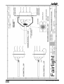
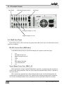
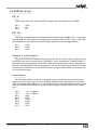
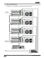
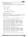
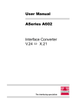
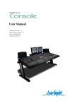
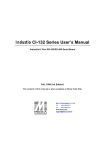
Installation Manual
Software Version 1.2n
Part Number: MANDADINS
Document Number: 122
Manual by: Andrew Brent
Norm Jackson
Steve Logan
Copyright © February 1998
Ref: DaDInst07.p65
T ABLE
OF
CONTENTS
Introduction. .................................................... 3
8. Maintenance .............................................. 16
DaD key features ........................................ 3
8.1 DaD Power Supply .............................. 16
8.2 Hardware Test Operations ................... 16
8.3 The Tests Submenu .............................. 16
Dsp ...................................................... 16
Scsi ...................................................... 17
Panel .................................................... 17
8.4 Loading software to the DaD .............. 17
8.5 DAD Programming Cable ................... 18
8.6 DAD Serial Port Logging ..................... 18
8.7 DAD Control Panel Ram Reset ............ 19
1. Cautions & Saftey Requirements .................. 4
1.1 Safety Precautions ................................. 4
1.2 EMC Warning ........................................ 5
1.3 External Cables ..................................... 5
1.4 Fuse ...................................................... 5
1.5 Mains Cables ........................................ 5
1.6 Cleaning ................................................ 5
1.7 Mains Plugs and Power Cords ............... 6
Mains Attachment Plugs ........................ 6
Mains Power Cords ................................ 6
Index .............................................................. 21
2. Specifications ............................................... 8
2.1 Mechanical ........................................... 8
Rack ...................................................... 8
Controller .............................................. 8
2.2 Electrical ............................................... 8
2.3 Audio .................................................... 8
3. Connections ................................................. 9
3.1 DaD Cpu Panel ..................................... 9
RS-232 Logger Port (DB9 Male) ............. 9
Video/Word Clock Sync (BNC x 2) ........ 9
3.2 DaD Aux Panel.................................... 10
LTC In .................................................. 10
LTC Out ............................................... 10
Control 1 and Control 2 ....................... 10
Cable Length ....................................... 10
3.3 DAD 4 Channel Output Card .............. 11
4. DaD Control Network ................................ 12
4.1 ATTENTION ........................................ 12
4.2 Control Network ID Assignment ......... 12
5. System Diagram ......................................... 13
6. Scsi Setup ................................................... 14
6.1 DaD Internal Scsi ................................ 14
6.2 DaD External Scsi ............................... 14
6.3 Assigning Scsi ID ................................. 14
7. Operation ................................................... 15
7.1 Creating DaD files on an MFX3plus .... 15
7.2 Loading and playing files on the DaD . 15
DaD Installation Manual
2
I NTRODUCTION .
This Manual describes specific information about the DaD product from Fairlight. In doing
so it is not possible to only describe the DaD, some information about how files are created on
the MFX for the DaD must also be included. You should find enough information for the technical user to install hardware and load a file for playback in an environment containing both
MFX3plus and DaD systems.
DA D
KEY FEATURES
Plug and play Compatability with MFX3plus.
Lock times of less than one second.
Locks and play’s audio in Reverse.
Supports sync from Video, Word Clock and LTC.
Plays 24 tracks with crossfades and EQ from one Hard Disk.
Boots from Flash ROM.
Software upgradeable from RS232 port on rear of unit.
3
DaD Installation Manual
1. CAUTIONS & S AFTEY R EQUIREMENTS
1.1 SAFETY PRECAUTIONS
1. Read Instructions - All the safety instruction should be read before the device is
operated.
2. Retain Instructions - The safety and operating instructions should be retained for
future reference.
3. Heed Warnings - All warnings on the device and in the operating instructions should
be adhered to.
4. Follow Instructions - All operating and use instruction should be followed.
5. Water and Moisture - The device should not be used near water - for example, near
bathtub, washbowl, kitchen sink, laundry tub, in a wet basement, or near a swimming pool etc.
6. Carts and Stands - The device should be used with a cart or stand that is recommended by the manufacturer.
7. Ventilation - The device should be situated so that its location or position does not
interfere with its proper ventilation. For example, the device should not be situated
on a bed, soft rug, or similar surface that may block the ventilation openings; or
placed in a built-in installation, such as a bookcase or cabinet that may impeded the
flow of air through the ventilation openings.
8. Heat - The device should be situated away from heat sources such as radiator, heat
registers, stoves or other appliances (including amplifiers) that produce heat.
9. Mains Power Cords - The equipment has an auto-sensing Power supply unit for
sensing the mains supply circuit voltage and can be operated under various Mains
Supply Voltages (100/110/220/240V). Only mains power cord and attachment plugs
approved by the standards authority in the country of use should be used to connect
the equipment to the alternate supply circuit voltage.
10. Grounding or Polarization - Precautions should be taken so that the grounding or
polarization means of the device is not defeated.
11. Mains Power Cord Protection - Mains Power cords should be routed so they are not
likely to be walked on or pinched by items placed upon or against them, paying
particular attention to the cords at plugs, convenience receptacles, and the point
where they exit from the device.
DaD Installation Manual
4
1.2 EMC WARNING
The DaD conforms to EMC directive 89/336/EEC standard Class A EN55022
EN50082.1.1995. As a class A device, it may cause radio interference in a domestic environment
in which case the user may be required to take adequate measures.
Installers should be aware that under the requirements of the EMC directive, both individual pieces of equipment and also complete installations must comply.
For information about EMC requirements please consult the following two references:
1) Ott, Henry W. "Noise Reduction Techniques in Electronic Systems"
John Wiley and Sons, 1988, 2nd ed.
ISBN 0-471-85068-3
2) Williams, Tim, "EMC for Product Designers"
Newnes Publishing, 1992,
ISBN 0-7506-1264-9
1.3 EXTERNAL CABLES
External cables should use braided shields in favor of foil shields.
External cables should use metal backshells for the connectors in favor of plastic or
metalised plastic.
The braided cable shields should be terminated at the backshells.
Feritte cores should be used on all cables near the connectors.
1.4 FUSE
To reduce the risk of fire, replace only with the same manufacturer, type and rating fuse. UL
listed or recognised fuse to be used only.
1.5 MAINS CABLES
All external cables are to be of UL listed or recognised type only
1.6 CLEANING
Do not use alcohol based cleaners on the DaD Console. A soap based solution is recommended. Ensure that the cloth is thoroughly wringed before attempting to wipe any panel or
faceplates. Do not spray cleaning agents directly onto the DaD Console. Apply to a Cloth and
then to the unit being cleaned.
5
DaD Installation Manual
1.7 MAINS PLUGS AND POWER CORDS
The following lists the recommended mains plugs and leads required for use in various
countries throughout the world.
MAINS ATTACHMENT PLUGS
Standards applicable
Country
ASTA BS1363 1984
UK
BS 546, 1950
India, Kenya, Nigeria, Kuwait, Parts of
Asia and the Far East
IEC695-2-1 & NF-USE
France and Belgium
DIN49441 & CEE 7 Sheet VII
Europe
SEV
Switzerland
CE123-16
Italy
MAINS POWER CORDS
Standards applicable
Country
CSA22.2 No. 42 & UL498
North America & Japan
ASE 1011 (1959)
Switzerland
CEI 2316
Italy
SRAF 1962
Denmark
AS3112-1990, NZSS198-1967
Australia, New Zealand, Fiji, Papua New
Guinea, Republic of China
DaD Installation Manual
6
7
DaD Installation Manual
2. S PECIFICATIONS
2.1 MECHANICAL
RACK
Width:
Height:
Depth:
19” Mounting, Front mounts only.
3 Units, 5 1/4” high.
15 1/4” (from front panel not including connectors.)
CONTROLLER
Width:
Height:
Depth:
14 1/2”
1 3/4” (at rear of controller)
7 1/4”
2.2 ELECTRICAL
Power Consumption:
Heat output:
100W
342 BTU’s
2.3 AUDIO
THD:
Noise:
Max Output:
Output Impedance:
DaD Installation Manual
0.05%
-90dB
+22dBu
<50Ohms
8
3. CONNECTIONS
Cpu Panel
Aux Panel
4 Channel Output Card #1
Analogue Outputs (1 to 4)
Digital Outputs (1 to 4)
3.1 DAD CPU PANEL
Each DaD unit has a CPU card with rear panel accessible to the user. The connectors on this
panel are as follows:
RS-232 LOGGER PORT (DB9 MALE)
A 38K Baud terminal may be attached to display or capture system messages.
1
2
3
4
5
6
7
8
9
n/c
RDI Receive Data In
TDO Transmit Data Out
n/c
GND
n/c
RTS Request To Send
CTS Clear To Send
n/c
VIDEO/WORD CLOCK SYNC (BNC
X
2)
These connectors accept standard Video Black signal for synchronizing the machine to
NTSC or PAL timing reference. They are also used to accept Word Clock if that is selected as
the Sync Source.
The 2 connectors provided are a loop through and may be used interchangeably. No
termination is provided by the DaD, so a normal multi-machine configuration would consist of daisy chained machines with a terminator on the spare BNC of the last machine.
9
DaD Installation Manual
3.2 DAD AUX PANEL
LTC IN
XLR Female Connector Balanced LTC timecode signal from Reference -20 dBm.
Pin 1
Pin 2
Pin 3
GND
IN+
IN-
LTC OUT
XLR Male Connector generates Balanced LTC timecode signal 0 dBm. This is not a loop
through from the LTC In port and cannot be used to daisy chain the LTC signal. A Distribution Amplifier or split from the main LTC feed is required to run multiple dubbers.
Pin 1
Pin 2
Pin 3
CONTROL 1
GND
OUT+
OUT-
AND
CONTROL 2
These are RJ-45 8 way Network connectors for the RS-485 control signals which join up
to 24 DaD units and 2 Control Panels. CONTROL 1 and 2 are identical ,a Control Panel or
other DaD unit may be connected to either. Note that Control Panels receive power from
the DaD CONTROL PORT they are plugged into. A DaD unit MUST be powered ON for the
Control Panel attached to it to function, however an unpowered DaD in a daisy chain will
not break the network.
CABLE LENGTH
RS-485 balanced lines are driven using Transceivers specified by the manufacturer to
operate over a distance of greater than 300 Feet. Minimize the cable length between Rack
units to avoid possible differences in Ground potential. Control Panels derive their ground
from the DaD Rack they attach to, so the user may employ a longer cable for this connection.
Pin 1
Pin 2
Pin 3
Pin 4
Pin 5
Pin 6
Pin 7
Pin 8
+12 V @ 500mA
+12 V @ 500mA
NET+
NET DATA+
DATAGND
GND
DaD Installation Manual
10
3.3 DAD 4 CHANNEL OUTPUT CARD
DaD Channel cards have provision for 4 Analog and 4 Digital outputs at the rear of the
machine. The Analog Output channels are identified as AO1, AO2, AO3, AO4.
Analog outputs follow the MFX convention assigned to a DB15 Male connector.
Pin 1
Pin 2
Pin 3
Pin 4
Pin 5
Pin 6
Pin 7
Pin 8
Pin 9
Pin 10
Pin 11
Pin 12
Pin 13
Pin 14
Pin 15
FG
GND 1
AO2+
AO2GND3
AO4+
AO4NC
AO1+
AO1GND2
AO3+
AO3GND4
NC
Digital outputs follow a new convention specific to the DaD. These AES pairs are assigned to
Digital Output Channels DO1/2 and DO3/4 and are available on a DB9 Male connector.
Pin 1
Pin 2
Pin 3
Pin 4
Pin 5
Pin 6
Pin 7
Pin 8
Pin 9
FG
DO3/4 GND
DO1/2GND
GND
DO3/4 +
GND
DO1/2+
11
DaD Installation Manual
4. D A D CONTROL N ETWORK
Up to 24 DaD Rack units and 2 Control Panels may be connected in a network. A daisy chain
configuration is used with Control Panels being attached to the ends of the chain. Each DaD
Rack has 2 Control ports whereas a Control Panel has only one. RJ-45 terminated cables are
provided with each DaD rack, however the user may supply longer ones if required. Any standard data cable may be used, providing pin to pin correspondence is maintained (i.e.
PIN1 -> PIN1, PIN2 -> PIN2, ... PIN8 -> PIN8).
Each DaD rack provides 12V @ 500mA to a Control Panel attached to either Control Port.
This supply is Diode Protected to ensure no current may flow between adjacent DaD Rack units
connected in a daisy chain.
4.1 ATTENTION
Existing 10BaseT PC LANs are not compatible with the DaD Control Network.
DO NOT plug a DaD network into any PC LAN device!
DO NOT attempt to use a 10BaseT HUB in any way!
PC Data cables are usually BLUE. If there is data cabling near your DaD installation, it
may be advisable to make DaD Control cables of a different color to avoid confusion.
4.2 CONTROL NETWORK ID ASSIGNMENT
For a Network of DaD units to function correctly, each device must have a unique ID to
avoid conflicts. DaD Rack units may be set as ID 1 -> 24. Control Panels may also have ID of 1 ->
24. The Control Network will not function correctly if either 2 Rack units share a common ID, or
if 2 Control Panels share a common ID. It is OK for a Rack and a Control Panel to have the same
ID.
Both Rack and Control Panel may be assigned an ID by the user. To do this, make a single
connection between one Rack and one Control Panel, power up the DaD and proceed to the
SETUP MENU. Set the desired address of both Rack and Control Panel. If you are setting up a
large network, repeat the above procedure for each Rack unit before connecting all machines in
a daisy chain.
Do not connect a network of DaD machines which have not been assigned a unique ID. This
may result in unpredictable operation where DaD racks or Control Panels may not be able to be
configured correctly.
DaD Installation Manual
12
5. S YSTEM DIAGRAM
The following is an example of a sync and control setup using 4 DaDs:
75 Ohm
Terminator
Video Sync
Rj45
LTC
DA or Split
13
DaD Installation Manual
6. SCSI S ETUP
6.1 DAD INTERNAL SCSI
The front of the DaD rack contains two half height drive bays to allow mounting of Removable Disk Drives or Optical devices with direct access from the front of the unit. Each bay is
supplied with it’s own 50 pin IDC connector and standard Molex power connector.
6.2 DAD EXTERNAL SCSI
External SCSI connection is available at the rear of the DaD via an Industry standard 50 way
Centronics connector. When not used this connector should have an Active SCSI Terminator
attached. Such a terminator is shipped with each DaD. When an external device or chain is
attached, the terminator should be connected to the end device.
WA R N I N G
The DaD uses an internal SCSI drive for system functions.
This drive always occupies SCSI ID 0!
If any other devices are connected with the SCSI ID 0 address, the internal operating
system and projects on the external device may be damaged or lost.
SCSI ID 7 is assigned to the DaD CPU and may not be used.
If internal SCSI devices are mounted in the Drive Bays, these will have been assigned addresses between 1 and 6. Use the SETUP:TEST menu to scan the SCSI bus if this information is
not known. Assign any unused addresses to each external SCSI device.
6.3 ASSIGNING SCSI ID
SCSI devices attached to the DaD may occupy ID 1 through ID 6. By default, the DaD will
scan the SCSI Bus and use the lowest ID device found as the location of project files. Since all
internal devices must be removable, forcing recognition of a particular device can be accomplished by removing any device on a lower ID. The DaD will find the next lowest ID simply by
using the LOAD MENU as usual.
Removable devices without media mounted will be bypassed. Knowing this a user can place
a removable Kingston at a low address so when inserted it will become the default device.
Assign a high address to a fixed external device so it will only be activated when all removable devices are not present.
The best ID assignment will depend on the preferred operating procedure used with the
DaD, contact your local Fairlight Office to discuss details specific to your installation.
The TEST MENU may be used to scan the SCSI BUS to identify all attached devices.
DaD Installation Manual
14
7. O PERATION
7.1 CREATING DAD FILES ON AN MFX3PLUS
DaD doesn’t play MFX3plus (.MT) files. It loads and play’s a new file format supported by
MFX3plus called MDL (.DL). DaD language files are created on an MFX3 plus in the following way:
1. Make sure the project which is to go to the DaD is on the intended removable hard
disk drive which will be physically taken to the DaD.
2. Open the intended project.
3. On the command line, type: MDL <return>
This will generate the MDL file on that Hard Disk. That’s it, remove the drive, take it to the
DaD and load the file in order to play it.
POINTS
TO WATCH:
1. The DaD can open extensions to the main file, just like MFX, however care needs to
be taken to make sure the audio for all the borrowed clips is resident on the drive
which will be taken to the DaD.
2. If you do intend to consolidate the project to one Hard Disk and one project without
extensions then don’t forget to do a dispose in the space menu prior to making the
MDL file. This will ensure that there is no attached projects to the project you wish to
take to the DaD.
3. If you make the MDL file on one drive, then copy the project to a new drive using
either Copy or Backup in the MFX, you must re-make the MDL file on the new disk.
4. The MDL is a global build of all clips on the top layer of the project. If you wish to
speed DaD loading then it is advisable to edit the project down to what only will be
playing on the stage. This will also help as far as disk usage optimization is concerned.
5. Ensure no clips cross over midnight (00:00:00:00). This will cause problems when
loading into the DaD.
7.2 LOADING AND PLAYING FILES ON THE DAD
Like the MFX the DaD boots up ready to load projects, known on the DaD as the title menu.
Pressing Softkey 2 (load button) will access the connected SCSI device and allow you to browse
the .DL files on the drive using the -. + keys on the Numeric Keypad. When the file you wish to
load is next to the arrow symbol in the DaD’s LCD display pressing enter on the keypad will load
the file. Loading the file is completed when the track key’s light up indicating the DaD has
material on that track and is ready to play. Pressing the chase key at this point will force the
DaD to lock to the incoming LTC.
For further details of loading/slipping and sync modes please see the DaD user manual.
15
DaD Installation Manual
8. MAINTENANCE
8.1 DAD POWER SUPPLY
The DaD rack unit incorporates an Auto Sensing Switch Mode Power Supply. This accepts an
IEC power cord and will function at 110/240 Volts at 50/60 Hertz. The Power Supply includes a
switched IEC out socket which may be used to power external devices such as Hard Drives and
MO units.
The Power Supply does not have any fuse or other user serviceable parts.
8.2 HARDWARE TEST OPERATIONS
When a DaD unit is powered on it will perform a number of Hardware tests to determine
whether all channel cards are performing correctly. These tests are as follows:1. Each Channel Card will be loaded with a diagnostic program which will test the basic
card operation.
2. Each Channel Card will perform memory tests to establish its Audio Buffer memory
is functional and error free.
Any errors will be logged to the DaD serial port, see the description under DaD programming cable on how to build a cable to make use of this feature.
8.3 THE TESTS SUBMENU
Additional tests may be performed using the controller as the user interface. These tests are
found in the setup menu which is in Title Page.
After Pressing the Tests Softkey the following tests are available.
DSP
Shows the presence of each DSP card and indicates whether operation is correct. Cards
which are shown as SICK or FAIL should be replaced.
Note: In this menu you are able to set the DSP clock rate.
This should be set to 60MHz
DO NOT CHANGE THIS!
The DSP speed should only be changed by authorised Fairlight personel for diagnostic
purposes. If instructed to do so, use the +/- keys. Press BOOT a second time to accept the
change and boot the DSPs at the selected rate. The selected rate is saved to disk so the
machine will automatically boot at the new rate forever more, or until you change it again.
By default, all DaD’s should boot at 60 MHz if you don’t touch this feature. Exit the menu to
change your mind. Don’t change the rate if you simply want to reboot the cards.
The BOOT option forces a reboot of all cards, during which a log of the operation is
written to the serial port. If your system has some problems, a Fairlight technician will tell
you how to extract a report from this log. The menu cannot be accessed while a project is
loaded.
DaD Installation Manual
16
SCSI
Scans the SCSI buss and shows all drives, with information about their address, vendor
and performance. The letter F indicates a fixed drive, while R indicates a removable. The
figure under Kb/s is a worst-case seek disk speed check, which causes the disk to read data
that is very widely spread across it’s surfaces. This is a good guide to the performance expectations of different disks used on the DaD.
Pressing SCAN repeats the tests. This may be done many times, if you are cabling the
system for example. Each time the test is run, a different DSP card is used, and this is reported as slot number. If bad results are obtained with a particular slot, it is likely that the
DSP card has a fault.
PANEL
All LED’s are lit, so failures can be spotted. In addition you may check the function of any
switch, or the jogger wheel, by activating them.
8.4 LOADING SOFTWARE TO THE DAD
With the DaD turned OFF connect the programming cable between either COM1 or COM2
on your PC and DaD serial port located at the back of the DaD unit. Next, insert the programming disk into drive A: or B: of the PC, copy the contents to a directory for DaD maintenance on
your PC, change directory to that new directory, and at the MS-DOS prompt type the command:
loader <port> <id> dad??.x
where <port> is either 1 or 2 depending on which COM port the cable is connected to,
<id> is a serial number which may be up to 9 digits long, and dad??.x is a file name of the system software module. The download program will display the following:
Copyright (c) Discrete Time Systems Pty. Ltd. 1995
Waiting for DaD-24T, press control-C to abort ...
after which you should turn the DaD ON and the software download will commence.
During the download process you will see the progression of the download displayed as
incrementing line numbers. You may also see the occasional communications error reported if
the UARTs in you PC are not the faster 16550A variety - however, this has no impact on the
loading process. When complete, a message of the type
Download is finished, ???? of ???? lines were transferred.
is displayed after which you may disconnect the programming cable from the DaD and
reboot it with the new software by turning it OFF and ON again.
17
DaD Installation Manual
8.5 DAD PROGRAMMING CABLE
A DaD programming cable can be made from the following description. It can be used for
both downloading software and diagnostic logging if a switch is installed on the DaD side of the
cable.
9pin female
(PC side)
pin 2 —
pin 3 —
pin 5 —
—
9pin female
(DaD side)
pin 3
pin 2
pin 5
pin 7 & 8 (via switch)
Software download - pin 7 & 8 - short circuit
Serial Port Logging - pin 7 & 8 - open circuit
8.6 DAD SERIAL PORT LOGGING
With a PC Connected to the RS232 port you can get useful information about how the DaD
is functioning as well as more detailed description’s of fault’s should they occur. Use a terminal
program on the PC and set it to 38K4 N81 and VT52 Terminal Emulation.
Power on the DaD.
On startup, automatic logging is enabled and DaD will dump the following to the PC:
logok (0,0.428) (idle): System started, logger enabled
logok (1,0.078) (disk): slot[0] no card seen (cpu card probably)
logok (2,0.562) (disk): card[1] booted ok, 60 MHz clock, 8 Mb buffer
logok (3,0.562) (disk): card[2] booted ok, 60 MHz clock, 8 Mb buffer
logok (4,0.562) (disk): card[3] booted ok, 60 MHz clock, 8 Mb buffer
logok (5,0.562) (disk): card[4] booted ok, 60 MHz clock, 8 Mb buffer
logok (6,0.562) (disk): card[5] booted ok, 60 MHz clock, 8 Mb buffer
logok (7,0.562) (disk): card[6] booted ok, 60 MHz clock, 8 Mb buffer
logok (8,0.003) (disk): Scanning SCSI bus...
logok (9,3.750) (disk): found disk[0,id_0,k_531,b_512,fixed,SC-2]
logok (10,0.001) (disk): (FUJITSU M2684S-512 2036 sync links tags)
logok (11,1.265) (user): Booting DaD[1] Version 1.2D Copyright DTS Jun 21
1997 04:27:09 [15:21]
logok (12,0.007) (chaser): TP Ident: 2.3 DTP
logok (13,0.026) (user): Starting dubber playback engine...
logok (14,0.542) (audio): card[1] booted ok, 60 MHz clock, 8 Mb buffer
logok (15,0.546) (audio): card[2] booted ok, 60 MHz clock, 8 Mb buffer
logok (16,0.546) (audio): card[3] booted ok, 60 MHz clock, 8 Mb buffer
logok (17,0.546) (audio): card[4] booted ok, 60 MHz clock, 8 Mb buffer
logok (18,0.546) (audio): card[5] booted ok, 60 MHz clock, 8 Mb buffer
logok (19,0.546) (audio): card[6] booted ok, 60 MHz clock, 8 Mb buffer
And then continue with other messages as the system is used.
There are some command’s which can be issued by the PC to the DaD when connected.
These are :
DaD Installation Manual
18
To dump the most recent 100 lines of log at any time, type:
log dump
(or “l du”)
This disables automatic logging as well, so type:
log all
(or “l”)
to re-enable it after dumping the log:
To Dump the task/process table with statistics gathered since last time this command was
given:
tasks
(or “t”)
To Dump system interrupt, message and control information since last time this command
was given:
audit
(or “a”)
To Dump some system related information:
stat
(or “s”)
To report the system software version:
version
(or “v”)
8.7 DAD CONTROL PANEL RAM RESET
If you find yourself with a Control panel which will not start-up you may have a situation
where the Non-Volatile RAM has become corrupted. It is possible to correct this problem in the
field with a PC, a terminal program and the DaD programming cable set to Serial port Logging
mode. Connect the one suspect panel to one DaD rack, connect the DaD rack to the PC and
verify that automatic logging is occurring. Then do the following:
NOTE: Make sure you type the following in lower case. Backspaces are not allowed, so if
you make a mistake you must press return and enter the line again.
You Type: cp sense 0
DaD Responds: control panel 0 responding
You Type: cp nr 0 16
DaD Responds: NVM RAM dump...
DaD Responds:
45 24 7 3 1 2 1 80 aa 56 0 26 c7 0 0 2e
(please note that the above may be different number’s on your faulty panel, it is not important)
You Type: cp nw 7 4 0 0x20 0x54 0x54
19
DaD Installation Manual
DaD Responds: cp reset (console will blink and restart)
logok (20,01:21) (Display): panel[1] found, attaching...
And the Log will continue.....
Remember to now set the id of the panel before re-connecting it back to the DaD network.
DaD Installation Manual
20
I NDEX
A
N
ANALOG OUTPUTS ..................................................................... 11
AUX PANEL ................................................................................... 10
AUX PANEL ................................................................................... 10
NETWORK ..................................................................................... 12
NETWORK ID ................................................................................ 12
NETWORK ID ASSIGNMENT ........................................................ 12
C
O
CABLE ............................................................................................ 18
CABLE LENGTH ............................................................................. 10
CLEANING ........................................................................................ 5
CONNECTIONS ............................................................................... 9
CONTROL NETWORK .................................................................. 12
CPU PANEL ...................................................................................... 9
CPU PANEL ...................................................................................... 9
CREATING A DAD FILE ................................................................. 15
CREATING DAD FILES .................................................................. 15
OPERATION .................................................................................. 15
OUTPUT CARD ............................................................................. 11
D
S
DIGITAL OUTPUTS ....................................................................... 11
SAFETY PRECAUTIONS ....................................................................4
SCSI ......................................................................................... 14, 17
SCSI ................................................................................................ 14
SCSI ID ........................................................................................... 14
SCSI SETUP .................................................................................... 14
SERIAL PORT LOGGING ............................................................... 18
SPECIFICATIONS .............................................................................. 8
SYNC ................................................................................................. 9
SYSTEM DIAGRAM ........................................................................ 13
P
POWER CONSUMPTION ................................................................ 8
POWER CORDS ............................................................................... 6
POWER SUPPLY............................................................................. 16
PROGRAMMING CABLE ............................................................... 18
E
EMC .................................................................................................. 5
EXTERNAL CABLES ........................................................................... 5
F
FEATURES ......................................................................................... 3
FUSE .................................................................................................. 5
T
H
TESTS SUBMENU .......................................................................... 16
HARDWARE TEST OPERATIONS .................................................. 16
HEAT OUTPUT ................................................................................. 8
V
VIDEO SYNC .................................................................................... 9
L
LOADING AND PLAYING FILES ................................................... 15
LOADING SOFTWARE .................................................................. 17
LOGGER PORT ................................................................................. 9
LTC ................................................................................................. 10
LTC IN: ........................................................................................... 10
LTC OUT ........................................................................................ 10
W
WORD CLOCK ................................................................................. 9
M
MAINS CABLES ................................................................................. 5
MAINS PLUGS .................................................................................. 6
MAINTENANCE ............................................................................. 16
21
DaD Installation Manual