1
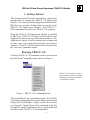
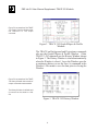
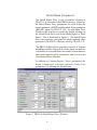
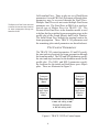
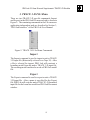
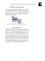
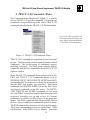
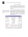
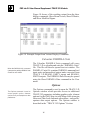
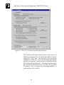
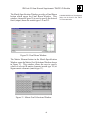
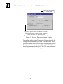
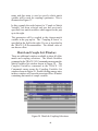
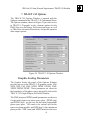
PBO Lab 2.0 User Manual Supplement: TRACE 3-D Module ™ PBO Lab 2.0 (Particle Beam Optics Laboratory) User Manual Supplement: TRACE 3-D Application Module Distributed by AccelSoft, Inc. P. O. Box 2813 Del Mar, CA 92014 USA (858) 677-0133 [email protected] www.ghga.com/accelsoft i PBO Lab 2.0 User Manual Supplement: TRACE 3-D Module PBO Lab 2.0 User Manual Supplement: TRACE 3-D Application Module 1999, 2001 by G. H. Gillespie Associates, Inc. All Rights Reserved. ISBN 1-892267-06-3 All rights reserved. No part of this book may be reproduced, in any form or by any means, without permission from the publisher. Printed in the United States of America. Published by AccelSoft Inc., San Diego, California. ii PBO Lab 2.0 User Manual Supplement: TRACE 3-D Module Included with this supplement is the following document, reproduced and distributed as part of a license agreement between G. H. Gillespie Associates, Inc. and the Regents of the University of California, operator of the Los Alamos National Laboratory (“LANL”): Appendix: “TRACE 3-D Documentation” TRACE 3-D Documentation, by K. R. Crandall and D. P. Rusthoi, Third Edition, May 1997. Los Alamos National Laboratory Report Number LA-UR-97-886 copyright 1987, 1990, 1997 by The Regents of the University of California. All Rights Reserved. TRACE 3-D is a FORTRAN program maintained and distributed by the Los Alamos Accelerator Code Group at LANL. The program is included with PBO Lab TRACE 3-D Application Module under a license agreement. Running TRACE 3-D is accomplished directly from the PBO Lab interface - the TRACE 3-D program is fully integrated with the PBO Lab environment. This supplement discusses the PBO Lab Commands and the output options for the TRACE 3-D Application Module. The TRACE 3-D program is described in the TRACE 3-D Documentation, which is included as Appendix A to this supplement. iii PBO Lab 2.0 User Manual Supplement: TRACE 3-D Module This page is intentionally blank. iv PBO Lab 2.0 User Manual Supplement: TRACE 3-D Module Table of Contents Chapter and Subject Page 1. Getting Started Running TRACE 3-D TRACE 3-D Elements Initial Beam Parameters Final Beam Parameters Plot Control Parameters 1 3 5 6 7 8 2. TRACE 3-D Output Text Output Window Graphic Output Window 11 13 13 3. TRACE 3-D File Menu Import Export 15 17 17 4. TRACE 3-D View Menu View Input File View Output File View Profile Data View Aperture Data View PARMILA Units View Match File 19 21 22 22 22 23 23 5. TRACE 3-D Commands Menu Beam Dynamics Commands Graph Beam Line Trace on Background Plot Projection Calculate Phase Advance Calculate Phase & Energy 25 28 28 30 31 32 32 v PBO Lab 2.0 User Manual Supplement: TRACE 3-D Module Chapter and Subject Page 5. TRACE 3-D Commands Menu (continued) Matching Commands Match Specification Perform Matching Calculate Mismatch Match and Couple Variables Display Commands Show Beam Vectors Show R Matrix Show Modified Sigma Calculate PARMILA Units Options 33 33 33 34 34 34 35 35 35 36 36 6. TRACE 3-D Matching Beam Matching Parameter Fitting TRACE 3-D Matching Types Find Matched Twiss Parameters Find Variables For Match Match and Couple Variables Match and Couple List Windows Matching the R and s Matrices Matching for Round Beam Matching for X,Y,Z Planes Matching for Phase Advance 37 42 43 46 46 46 47 49 50 50 50 51 7. TRACE 3-D Options Graphic Scaling Parameters Element Options Profile and Aperture Options Generate Aperture File Generate Profile Data 53 55 56 57 57 57 Appendix: “TRACE 3-D Documentation” 59 vi TM TM PBO Lab 2.0 PBO Lab 2.0 User Manual Supplement: TRACE 3-D Module Getting Started User Manual Supplement: TRACE 3-D Application Module 1 PBO Lab 2.0 User Manual Supplement: TRACE 3-D Module This page is intentionally blank. 2 PBO Lab 2.0 User Manual Supplement: TRACE 3-D Module 1. Getting Started This Getting Started Section is intended as a quick start introduction for running the TRACE 3-D Application Module. The remainder of this Supplement describes the PBO Lab user interface features that are specific to the TRACE 3-D Application Module. The TRACE 3D Documentation describes the TRACE 3-D program. When the TRACE 3-D Application Module is installed in PBO Lab, a TRACE 3-D option will be added to the Application Context pop-up in Document windows. The Application Context is used to indicate native inputs and in some cases access application-specific user interface windows. TRACE 3-D sub-menus will also be placed in the View and Commands menus. Running TRACE 3-D A Variety of TRACE 3-D commands can be executed from the pull-down Commands menu, shown in Figure 1. TRACE 3-D Commands include a variety of beam dynamics, matching and display commands for the TRACE 3-D Application Module. Figure 1 TRACE 3-D Commands Menu. The Graph Beam Line command generates the TRACE 3-D beam envelopes and phase-space ellipses in the Graph Ellipses & Profile Window. Figure 2 shows the result of executing the Graph Beam Line command using the Example B model distributed with the application and described in the TRACE 3-D Documentation. 3 PBO Lab 2.0 User Manual Supplement: TRACE 3-D Module Figure 2 is an example of the TRACE 3-D Graphic Output Window after the execution of the Graph command. Figure 2 TRACE 3-D Graph Ellipses & Profile Window. The TRACE on Background and Projections commands also use the Graph Ellipses & Profile Window. Other TRACE 3-D Commands use the History Window shown in Figure 3. The History Window is cleared automatically when the Window is closed. Leave the Window open for a continuous history or use the Save As command in the Window’s File menu to save the data prior to closing the Window. Figure 3 is an example of the TRACE 3-D History Window after a series of output commands were executed. The History Window is editable and its content can be saved to a disk file. Figure 3 TRACE 3-D History Window. 4 PBO Lab 2.0 User Manual Supplement: TRACE 3-D Module TRACE 3-D Elements There are several elements supported by PBO Lab which are not supported by TRACE 3-D. These are treated as zero length drift elements in the execution of a TRACE 3-D command and will have no effect on dynamics calculations. Figure 4 lists all of the beamline pieces supported by TRACE 3-D. Type Piece Piece Code Icon Type Type Piece Piece Code Icon Type - Initial Beam 8 Bend 1 Drift 9 Edge 2 Thin Lens 10 Radio Frequency Gap 3 Quadrupole 11 RFQ 4 Permanent Magnet Quadrupole 12 Radio Frequency Cavity 5 Solenoid 13 Tank 6 Doublet 14 Wiggler 7 Triplet 15 Rotate - Marker - Final Figure 4 PBO Lab Pieces supported by TRACE 3-D. 5 TRACE 3-D native inputs are indicated in each Piece Window with green dots which appear to the right of a parameter. Initial Beam Parameters The Initial Beam Piece is not a beamline element in TRACE 3-D, it is a specialized PBO Lab piece. However, the Initial Beam Piece parameters are used define the initial emittances (EMITI) and the initial Twiss parameters (BEAMI) inputs for TRACE 3-D. As with other Piece Windows this window is opened by double clicking on the Initial Beam Piece icon in the Model Space or Work Space. This is illustrated in Figure 5. The Initial Beam Piece also provides a tab panel for initial centroid offset parameters (BEAMCI) which are used by TRACE 3-D. The PBO Lab Beam Piece provides a variety of features including scalable ellipse plots of the beam parameters, calculation of equivalent Semi-Axis and Twiss parameters and initial centroid offset parameters, and access to the Correlation Matrix Window. In addition to Courant-Snyder (Twiss) parameters the Beam Parameters selection includes Semi-Axis parameters for defining the Initial Beam. Figure 5 PBO Lab Initial Beam Piece Window. 6 The Semi-Axis parameters are not supported directly by TRACE 3-D, however they can be used to specify an initial Sigma matrix input for TRACE 3-D using the Correlation Matrix Window. The Correlations button in the Initial Beam Window opens the Correlation Matrix Window. This window is used to specify an Initial Sigma Matrix for TRACE 3-D. The Correlations button is only active with the Semi-Axis Beam Parameters Selection. The Initial Sigma Matrix (SIGI) and the TRACE 3-D flag (IBS) are assigned when the Semi-Axis Beam Parameters are selected. The Particle Distribution Type specified in the Beam Piece Window is not used for TRACE 3-D. The Comp From Axis Button in the Beam Piece Window computes the Twiss Parameters from the Semi-Axis Parameters and the Correlations Matrix. If the Beam Parameters selection is Semi-Axis then the Comp From Twiss button will calculate Semi-Axis and Correlation values from the current Twiss Parameters. Final Beam Parameters The Copy From Output button copies the TRACE 3-D Output Beam Twiss parameters (BEAMO) into the Twiss parameters of the Initial Beam Piece (BEAMI). The Copy From Final button copies the Twiss parameters specified in the Final Beam Window (BEAMF used for matching) into the Twiss parameters of the Initial Beam Piece (BEAMI). These buttons provide the TRACE 3D Exchange Beams functionality described in Section 10.24 of the TRACE 3-D Documentation. An unlimited number of Beam Pieces may be stored on the Work Space and can be used to save copies of the TRACE 3-D BEAMI, BEAMF and BEAMO beam vectors. The Final Beam Twiss parameters (BEAMF, used for matching) are set via a similar window which can be opened in the Matching Specification Window. The Final Beam Window can also be opened by double clicking on a “Final” Piece icon and pressing the New Constraints button. The Final Beam Window also provides buttons to copy the Initial Beam Twiss parameters and the TRACE 3-D output beam vector. Unlike the Initial Beam Piece, the Final Beam parameters are not contained in a PBO 7 Refer to Sections 9.2 and 10.24 of the TRACE 3-D Documentation. The Beam and Final Pieces are used to define the start and stop locations for beam propagation through the beamline model. Lab beamline Piece. There is only one set of Final Beam parameters for each PBO Lab Document, although these parameters may be accessed through the Final Piece. Multiple Final Pieces do not create multiple Final beam parameter sets. The Final Piece in PBO Lab is used as a special type of Marker Piece for TRACE 3-D. The location of the Final Piece in the beamline model is used to define the the point that beam propagation stops in the profile plot of the Graph Ellipses and Profile Window. The Initial Beam Piece defines the starting location for beam propagation. These TRACE 3-D parameters and the remaining plot control parameters are described next. Plot Control Parameters The TRACE 3-D control parameters: N1 and N2 specify the start and stop locations for beam propagation through the beamline model. The NP1 and NP2 parameters specify the start and stop locations for the beamline model in the profile plot. The NEL1 and NEL2 parameters specify the locations for the initial and final phase space ellipse plots. These are illustrated in Figure 6. Transverse Phase-Space Ellipses at Transverse Phase-Space Ellipses at NEL1 NEL2 Longitudinal Phase-Space Ellipse at Longitudinal Phase-Space Ellipse at NEL1 NEL2 Plot Beamline Model Starting at NP1 and ending at NP2 Propagate BeamStarting at N1 and ending at N2 Figure 6 TRACE 3-D Plot Control inputs. 8 The locations of the both the Initial and Final Pieces in the beamline model are used to define the TRACE 3D plot control parameters: N1 and N2. There must be an Initial Beam Piece in the beamline model to execute TRACE 3-D. However, a Final Piece is not required. If there is no Final Piece in the model then the sequence of the last Piece in the Model used to define N2. If there are multiple Initial Beam Pieces in the model then the right most Beam Piece will be used. If there are multiple Final Pieces in the model than the left most Final Piece will be used. The model is sequenced left to right. N1 is initially assigned the sequence of the Initial Beam Piece and N2 the Final Beam Piece. TRACE 3-D supports forward and backward beam propagation. The direction is determined by comparing the N1 and N2 values. If N1 < N2 then forward propagation is used with N1=N1+1 and N2=N21. If N1 > N2 then beam propagation is backward. By default NP1=NEL1=N1 and NP2=NEL2=N2. However, a Marker Piece (or Final Piece) may be used to specify alternate locations for NP and NEL parameters. Figure 7 Final (Marker) Piece Window. 9 There must be an Initial Beam Piece in the beam line model in order to execute TRACE 3-D. All pieces are sequenced including Pieces which are not supported as beamline elements by TRACE 3-D. Unsupported Pieces are defined as zero length drift elements in TRACE 3-D. PBO Lab 2.0 User Manual Supplement: TRACE 3-D Module Figure 7 illustrates the Final Piece Window which is similar to the general Marker Piece Window. The New Constraints button opens the Matching Specification Window. The New Diagnostics button opens the Plot Control Window shown in Figure 8. Figure 8 Plot Control Window. Markers for NP are only valid outside the range of N1N2, e.g. NP1 <= N1 and NP2 >= N2 for forward propagation and NP1 >= N1 and NP2 <= N2 for backward propagation; Markers for NEL are only valid inside the range of N1-N2, e.g. NEL1 >= N1 and NEL2 <= N2 for forward propagation and NEL1 <= N1 and NEL2 >= N2 for backward propagation. The last valid Marker for NP1 (left to right) is used to assign the NP1 value and the first valid Marker for NP2 (left to right) is used to assign the NP2 value. The last valid Marker for NEL1 (left to right) is used to assign the NEL1 value and the first valid Marker for NEL2 (left to right) is used to assign the NEL2 value. This Getting Started Section is only intended to provide the user with a brief overview of the PBO Lab TRACE 3D Application Module. Refer to the PBO Lab User Manual for more general information on the PBO Lab user interface. The remainder of this Section provides more information on the material presented in the Getting Started Section, as well as other important subjects on the use of TRACE 3-D in PBO Lab. All users are encouraged to read the entire User Manual. 10 PBO Lab 2.0 TM TM TRACE 3-D Output User Manual Supplement: TRACE 3-D Application Module 11 This page is intentionally blank. 12 PBO Lab 2.0 User Manual Supplement: TRACE 3-D Module 2. TRACE 3-D Output Output from TRACE 3-D is sent to two different windows in PBO Lab. Text and numerical data is sent to the TRACE 3-D Text Output Window. Graphic output such as beam envelopes and phase-space ellipses are drawn in the TRACE 3-D Graphic Output Window. Additional output such as Aperture and Profile data, PARMILA Units data and Matching data are written to disk files which can be opened from the View menu. Text Output Window Text output from TRACE 3-D is sent to the TRACE 3-D Text Output Window. The Text Output Window has a default size and location but can be resized in both vertical and horizontal directions. Text output is appended to previous output when this window remains open. Closing the window will clear the previous content. File, Edit and Font menus provide the standard commands in the Text Output Window, including the Save As command which can be used to save the output from TRACE 3D to a named text file prior to closing the window. The Text Output Window is cleared automatically when the window is closed. Leave the window open for continuous history or use the Save As command to save the data prior to closing the window. Graphic Output Window Graphic output from TRACE 3-D is sent to a graphic output window. The Graphic Output window has a default size and location but can be resized in both vertical and horizontal directions. The current window contents are re-scaled when the window is resized. The graphic output window can be resized, positioned and left open for subsequent graphic commands. The size is only limited by the size of the monitor. Graphic output can not be sent to the window if it has been minimized. 13 When resized the Graphic Output window will scale the output for the new size. PBO Lab 2.0 User Manual Supplement: TRACE 3-D Module This page is intentionally blank. 14 PBO Lab 2.0 TM TM TRACE 3-D File Menu User Manual Supplement: TRACE 3-D Application Module 15 This page is intentionally blank. 16 PBO Lab 2.0 User Manual Supplement: TRACE 3-D Module 3. TRACE 3-D File Menu There are two TRACE 3-D specific commands: Import and Export, in the PBO Lab File menu which is shown in Figure 9. The remaining commands in the File menu are application independent and are described in Section 3, “PBO Lab Interface” of the PBO Lab User Manual. Figure 9 TRACE 3-D File Menu Commands. Import The Import command is used to import a native TRACE 3-D input file (Historically referred to as Tape 30). After a file is selected for import, PBO Lab will construct a beamline model from the native TRACE 3-D input file. The resulting model can then be saved as PBO Lab model file. Export The Export command is used to export a native TRACE 3-D input file. After a name is specified for the Export file, PBO Lab will write the native TRACE 3-D formatted input file for the beam line model in a PBO Lab Document window. 17 PBO Lab 2.0 User Manual Supplement: TRACE 3-D Module This page is intentionally blank. 18 TM TM PBO Lab 2.0 PBO Lab 2.0 User Manual Supplement: TRACE 3-D Module TRACE 3-D View Menu User Manual Supplement: TRACE 3-D Application Module 19 This page is intentionally blank. 20 PBO Lab 2.0 User Manual Supplement: TRACE 3-D Module 4. TRACE 3-D View Menu There are six commands in the PBO Lab View menu that are specific to viewing TRACE 3-D data files. Figure 10 shows the TRACE 3-D View sub-menu. The remaining commands in the View menu are application independent and are described in Section 3, “PBO Lab Interface” of the PBO Lab User Manual. Figure 10 TRACE 3-D View Menu Commands. View Input File The Input File command is used to create and view a native TRACE 3-D input file (Tape 30) which is generated by PBO Lab from the Document beamline model. This command will create a “Trace3DInput” ASCII text file (any previous file is overwritten) and that file will be opened in an editable text window. The standard File, Edit and Font menus are provided. The Save As command can be used to save the input file with a unique name. Access to the TRACE 3-D native input file is provided for informational purposes, the text file is not used to execute TRACE 3-D. PBO Lab implements a dynamic data interface with the TRACE 3-D application. 21 View Output File Beam Dynamics commands are described in in the TRACE 3-D Commands Menu Section. The Output File command is used to create and view a native TRACE 3-D data file (historically referred to as Tape 31) which is generated by PBO Lab from the data returned by TRACE 3-D after execution of a Beam Dynamics command. The format of this data file is the same as the Tape 30 input file. However, the output file will also contain return data such as the output beam (BEAMO) and the output emittances (EMITO), for a previously executed TRACE 3-D Beam Dynamics command. View Profile Data The Profile Data Option is accessed with the TRACE 3-D Options command in the Commands menu. The Profile Data command is used to open an existing “Profile Data” file. The profile data file will be opened in an editable text window. The standard File, Edit and Font menus are provided. The Save As command can be used to save the input file with a unique name. The Profile Data file is created during the execution of the Graph Beam Line command when the Profile Data Option has been selected in the TRACE 3-D Options window. With each execution of the Graph command a new Profile Data file will be created, over writing any previous file. View Aperture Data The Aperture Data Option is accessed with the Options command in the Commands menu. The Aperture Data command is used to open an existing “Aperture Data” file. The aperture data file will be opened in an editable text window. The standard File, Edit and Font menus are provided. The Save As command can be used to save the input file with a unique name. The Aperture Data file is created during the execution of the Graph Beam Line command when the Aperture Data Option has been selected in the TRACE 3-D Options window. With each execution of the Graph command a new Aperture Data file will be created, over writing any previous file. 22 View PARMILA Units The PARMILA Units command is used to open an existing “PARMILA Units” file. The PARMILA Units file will be opened in an editable text window. The standard File, Edit and Font menus are provided. The Save As command can be used to save the input file with a unique name. This command will not generate the file if it does not exist in the application directory. The PARMILA Units file is created with the Compute PARMILA Units command in the Commands menu. The file contains unnormalized input units and normalized output units converted from TRACE 3-D BEAMI, BEAMO, EMITI, and EMITO parameters. When the PARMILA Units command is executed, any existing PARMILA Data file will be over written. View Match File The Match Output command is used to view the “match.out” data file which is generated during a Perform Matching command. The match output file will be opened in an editable text window. The standard File, Edit and Font menus are provided. The Save As command can be used to save the input file with a unique name. Match specification and execution are described in the “TRACE 3-D Matching” Section. 23 The match output file will be over written on each execution of the Perform Matching command. PBO Lab 2.0 User Manual Supplement: TRACE 3-D Module This page is intentionally blank. 24 TM TM PBO Lab 2.0 PBO Lab 2.0 User Manual Supplement: TRACE 3-D Module TRACE 3-D Commands Menu User Manual Supplement: TRACE 3-D Application Module 25 PBO Lab 2.0 User Manual Supplement: TRACE 3-D Module This page is intentionally blank. 26 PBO Lab 2.0 User Manual Supplement: TRACE 3-D Module 5. TRACE 3-D Commands Menu The Commands menu illustrated in Figure 11, is used to execute TRACE 3-D specific commands. The majority of commands correspond directly to the native TRACE 3-D commands described in the TRACE 3-D Documentation. Most of the PBO Lab TRACE 3-D Commands correspond directly to the native TRACE commands described in the TRACE 3-D Documentation. Figure 11 TRACE 3-D Commands Menu. TRACE 3-D Commands are organized in four functional groups. The first group contains beam dynamics related commands. The second group of commands support matching operations. The third group contains display commands and the last command is for the TRACE 3-D Options window. Some TRACE 3-D commands that are not present in the PBO Lab TRACE 3-D Commands menu such as NEWFILE, INPUT, ADD, DELETE, QUERY and SAVE are found in the File menu or are effectively incorporated into the PBO Lab graphic user interface. Equivalent commands for NEWFILE in PBO Lab are the New, Open and Import commands in the File menu. The INPUT, ADD, DELETE and QUERY commands are not used since the PBO Lab interface handles these functions with graphical beamline set up and access to element parameters by double-clicking Pieces in the beamline model. The SAVE command equivalents in PBO Lab are the Save, Save As and Export commands in the File menu. The END command is equivalent to Exit in the File menu. These menu commands are discussed in Section 3 “PBO Lab Interface” in the PBO Lab User Manual. Two other 27 PBO Lab 2.0 User Manual Supplement: TRACE 3-D Module TRACE 3-D commands, CENTROID and APERTURE are integrated into the PBO Lab user interface. The CENTROID equivalent in PBO Lab is the Centroid Parameters tab panel in the Initial Beam Piece, which provides access to beam centroid offsets. The APERTURE command is implemented in PBO Lab as a user option. This is described in the “TRACE 3-D Options” Section. Most TRACE 3-D commands result in output to one of two different TRACE 3-D output windows. Graph Beam Line, Trace on Background and Plot Projections commands send graphics to a Graphic Output Window. Other Beam dynamics commands and the display commands send text to a Text Output window. Beam Dynamics Commands There are five commands in the Beam Dynamics group of the TRACE 3-D Commands menu. Each of these commands are described here. Graph Beam Line The Graph Beam Line command generates beam envelopes and phase-space ellipses in the Graphic Output window. The Graph Beam Line command generates the TRACE 3-D beam envelopes and phase-space ellipses in the Graphic Output window. Figure 12 shows the result of executing the Graph Beam Line command using the Example B model distributed with the application and described in the TRACE 3-D Documentation. The beamline elements are drawn first in the profile box at the bottom of the window. The initial phase space ellipses are then drawn. Horizontal (solid red) and vertical (dashed blue) ellipses in the top plot and longitudinal (dashed green) in the bottom plot. If the Initial Piece is to the right of the Final Piece in the beamline model, then the initial ellipses will be drawn on the left-hand side of the window; if the Initial Piece is to the right of the Final Piece in the beamline model then the beam traverses the model in the reverse direction and the initial ellipses will be drawn on the right-hand side of the window. 28 PBO Lab 2.0 User Manual Supplement: TRACE 3-D Module Figure 12 Output from the Graph Beam Line Command. Beam envelopes are then drawn in the beam profile box at the bottom of the window. The horizontal (solid red) and longitudinal (dotted green) beam profiles in the upper half of the profile box and the vertical (dashed blue) profile in the lower half. After the beam envelopes are complete, the final ellipses are drawn followed by various parameter values which are displayed in the center of the window as shown in Figure 12. 29 PBO Lab 2.0 User Manual Supplement: TRACE 3-D Module Trace on Background The Trace on Background command generates beam envelopes and phase-space ellipses over the output from a previous Graph Beam Line command. The Trace command will be dimmed if a Graph command has not be executed. The Trace on Background command generates an overlay of beam envelopes and phase-space ellipses in the current Graphic Output Window. The Trace on Background command is not useful if the beamline length has been changed or the Graphic Output Window has been resized since the last Graph command. The Graphic Output window must be left open after a Graph command to use the Trace on Background command. Figure 13 shows the results from the Trace on Background command over the Graph example illustrated in Figure 16. Figure 13 Output from the Trace on Background Command. 30 PBO Lab 2.0 User Manual Supplement: TRACE 3-D Module Plot Projections The Plot Projections command requires the previous execution of a Graph command and will be dimmed if a Graph command has not be executed. Projections of the beam in x-y, x-z and x-∆p/p are displayed in the Graphic Output window. The upstream end of the system is shown on the left-hand side of the window and the downstream end on the right. Figure 14 shows the resulting display after executing the Plot Projections command. The Plot Projections command is used to plot initial and final projections on x-y, x-z and x-∆p/p planes. Figure 14 Output from the Plot Projections Command. 31 Calculate Phase Advance The Calculate Phase Advance command calculates and displays the phase advance and Twiss parameters for the three phase-space planes. The Calculate Phase Advance command is used to calculate and display the phase advance (σ) and the Twiss (α & β) beam ellipse parameters for each of the three phase-space planes. This command requires a previous execution of the Graph command. The phase advance is given in degrees, alpha and beta are in mm/mrad. The results are sent to the Text Output window. An example of the resulting output from this command is shown in Figure 15. Calculate Phase & Energy The Calculate Phase & Energy command is used to calculate and display information about the the longitudinal plane of the output beam. This includes the phase and energy of the beam center, the phase and energy half-widths, the length on the longitudinal semi axis, the half-width and the longitudinal emittance. An example of the resulting output from the Calculate Phase & Energy command is shown in Figure 15. Refer to Section 10.23 in the TRACE 3-D Documentation for additional information on Phase and Energy. Figure 15 Output from Calculate Phase Advance and Calculate Phase & Energy Commands. 32 Matching Commands There are five different matching related commands in the TRACE 3-D commands menu. These are briefly described here. The “Matching Options” Section describes the steps for setting the match type and specifying match and couple variables for a matching problem. Match Specification The Match Specification command opens the TRACE 3D Match Specification window. Depending on the particular match type selected, TRACE 3-D will attempt to find matched-ellipse parameters or values for specified match variables, in order to fit the final beam or specified matrix elements. The match procedure searches for a solution to a set of nonlinear, simultaneous equations in an iterative procedure. The maximum number of iterations (NIT) and the matching tolerance (DELTA) are set in the Match Specification Window as described in the “Matching Options” Section. If a solution has not been found within the specified number of iterations, then the match variables will be set to the values found which minimize the convergence factor. Perform Matching The Perform Matching command is used to start the matching process. The match type must be set prior to execution of this command. Output from the matching process includes the convergence factor and the values for each of the match variables. This data is written to the match.out file for each iteration. Matching will proceed until the maximum number of iterations has been reached or when the convergence factor falls below the 33 The “Matching Options” section describes the steps for setting the match type and specifying match and couple variables for a matching problem. user specified Tolerance. The final values calculated for the selected match variables and the associated convergence factor are sent to the Update Match Variables window as described in the “Matching Options” Section. Calculate Mismatch For a definition of the TRACE 3-D mismatch factor refer to the TRACE 3-D Documentation. The Calculate Mismatch command calculates and displays the mismatch factor between the output beam (BEAMO) and the desired final beam (BEAMF). Note that a match type must be set in the Match Specification window. Output from the Calculate Mismatch command is sent to the Text Output window. Match and Couple Variables The Match and Coupling windows are discussed in the “Matching Options” Section. The Match Variables command opens the TRACE 3-D Match Variables window which displays the current match variable selections and there values. The Coupled Variables command opens the TRACE 3-D Coupling Variables window which displays the currently selected TRACE 3-D coupling variables and their associated match variables. Display Commands A variety of commands are available for displaying data before and after a Graph command has been executed. Most of these commands display data calculated from a previous Graph command. Figure 16 illustrates the Text Output window after executing the Show Beam Vectors, Show R-Matrix and Show Modified Sigma commands. This output is from Example B after matching to convergence. 34 Show Beam Vectors The Show Beam Vectors command is used to display all of the TRACE 3-D beam vectors. The initial beam (BEAMI), the final beam (BEAMF) and the output beam (BEAMO) are displayed, followed by the beam centroid offsets (BEAMC) and the initial beam centroid offsets (BEAMCI). The output for this command is illustrated in Figure 18. The output beam (BEAMO) must be calculated in a previous Graph command. Show R Matrix When a Graph command is executed the 6x6 transfer matrix is stored in the RM array. The Show R Matrix command displays this R matrix. A description of the R matrix for each element can be found in Section 6 “Transfer Matrices” in the TRACE 3-D Docu-mentation. An example of the output generated by this command is illustrated in Figure 18. Show Modified Sigma The Show Modified Sigma command displays the modified Sigma matrix in the Text Output window in the format shown in Figure 17. Output from the Show Modified Sigma command is shown in Figure 16. x max x 'max y max y 'max z max ∆p max p r12 r13 r14 r15 r16 r 23 r 24 r 25 r 26 r 34 r 35 r 36 Because the Sigma matrix is a symmetric matrix, only half of the elements are displayed. r 45 r 46 r 56 Figure 17 Modified Sigma Matrix Format. 35 PBO Lab 2.0 User Manual Supplement: TRACE 3-D Module Figure 18 shows of the resulting output from the three display commands: Show Beam Vectors, Show R Matrix, and Show Modified Sigma. Figure 18 Example Output from Various Display Commands. Calculate PARMILA Units When the PARMILA Units command is executed any existing PARMILA Data file will be over written. The Calculate PARMILA Units command will cause TRACE 3-D to calculate and write the “PARMILA Units” file. This file will then be opened in a text window. The PARMILA Units file contains PARMILA unnormalized input units and normalized output units converted from TRACE 3-D BEAMI, EMITI, inputs and BEAMO, EMITO outputs. The PARMILA Data file may be opened using the Show PARMILA Data command in the View menu. Options The Options command is used to access graphic scales, element options and profile/aperture data preferences. The Options command is used to open the TRACE 3-D Options window which provides access to additional TRACE 3-D parameters, including graphic scales, element options for the PMQ Step size and fringe field extension factor and Thin Lens chromatic aberrations, and profile/ aperture data output options. The Options window is described in the “TRACE 3-D Options” Section. 36 TM TM PBO Lab 2.0 PBO Lab 2.0 User Manual Supplement: TRACE 3-D Module TRACE 3-D Matching User Manual Supplement: TRACE 3-D Application Module 37 PBO Lab 2.0 User Manual Supplement: TRACE 3-D Module This page is intentionally blank. 38 PBO Lab 2.0 User Manual Supplement: TRACE 3-D Module 6. TRACE 3-D Matching The matching capabilities of TRACE 3-D are among its most powerful features. This section discusses the use of PBO Lab to implement the various matching options available in TRACE 3-D. The set up of matching problems is the focus of this section. The Match commands are discussed in the “TRACE 3-D Commands Menu” Section. Fourteen different beam matching or parameter fitting options are available in TRACE 3-D. The match type (MT) indicates the type of matching desired. Types 1-4 specify that matched Twiss parameters are to be found. Type 13 specifies that initial Twiss parameters are to be found to fit desired final Twiss parameters. Types 5-12 specify that values are to be found for selected element parameters to fit final Twiss parameters, or to fit selected R matrix or Sigma matrix elements. Type 14 specifies that values are to be found for selected element parameters to fit for desired phase advances in selected phase planes. TRACE 3-D supports fourteen different types of beam matching and fitting. The PBO Lab TRACE 3-D Match Specification Window shown in Figure 19 is used to set the match type and to access other matching parameters. Matching types are divided into two groups: “Find Matched Twiss Parameters” and “Find Variables For Match”. Match types 1-4 are used to find matched Twiss parameters, similarly match type 13 varies initial Twiss parameters to match for desired final Twiss parameters. Match types 5-12 are used to find variables for a match by varying element parameters. Match types are divided into Beam Matching and Parameter Fitting groups. 39 PBO Lab 2.0 User Manual Supplement: TRACE 3-D Module Figure 19 TRACE 3-D Match Specification Window. The Match Specification window also provides access to additional parameters for the maximum number of match iterations (NIT) and the tolerance for matching convergence (DELTA). All of the matching procedures use the convergence criteria which are specified in the Match Specification Window. Matching is terminated if the calculated mismatch factor is below the specified Tolerance value or when the maximum number of iterations has been reached. 40 PBO Lab 2.0 User Manual Supplement: TRACE 3-D Module The Match Specification Window provides a Final Beam button which opens the Final Beam Window. This window, shown in Figure 20 is used to specify the desired final (output) beam for match types 5-9 and 12. Figure 20 Final Beam Window. The Matrix Element button in the Match Specification Window opens the Matrix Goal Selections Window shown in Figure 21. This window allows the user to specify values of selected R matrix elements (match type 10) or Sigma matrix elements (match type 11). Figure 21 Matrix Goal Selections Window. 41 A detailed definition of the mismatch factor can be found in the TRACE 3-D Documentation. PBO Lab 2.0 User Manual Supplement: TRACE 3-D Module For match type 14, the Phase Advances button is used to open the window shown in Figure 22 in order to fit for specified phase advances in the selected phase planes. Figure 22 Match for Phase Advances in Selected Phase Planes. Beam Matching (Find Matched Twiss Parameters) Beam Matching procedures are specified in the Match Specification Window. The Initial Beam Twiss Parameters are varied with these procedures but they are not explicitly selected as match variables. The Perform Matching command in the TRACE 3-D Commands menu is used to execute the matching procedure. Following the matching procedure, the Update Beam Parameters window, shown in Figure 23 is automatically opened. The Initial Beam Parameters will not be updated in the beamline model until they are explicitly updated by the user. Parameters may be updated individually or all at once. All parameter updates must be made prior to closing the window. Continue the matching procedure with additional executions of the Perform Matching command after updating the beam parameters. The variables for each match iteration and the associated mismatch factor are written to the “match.out” file which can be opened with button in the Update Window or by using the match output View menu command. 42 PBO Lab 2.0 User Manual Supplement: TRACE 3-D Module Figure 23 TRACE 3-D Beam Update Window. Parameter Fitting (Find Variables For Match) Parameter Fitting procedures are specified in the Match Specification Window. The beamline element parameters varied with these procedures must be explicitly selected as match variables in the Special Parameter Setting window. The S-Window, shown in Figure 24 is accessed with the S-button located to left of the parameter name in the Piece Windows of beamline elements. Application specific inputs are accessed in the TRACE 3-D tab panel of the Special Parameter Settings Window. The example in Figure 24 shows the Magnetic Field Gradient parameter being selected as a match variable in the Quadrupole element labeled QUAD1. 43 PBO Lab 2.0 User Manual Supplement: TRACE 3-D Module Application Independent Variable Name Application Specific settings for TRACE 3-D include specifying parameter as a Match Variable, Coupled to a Match Variable or as an Import Parameter. Figure 24 Special Parameter Setting Window. Depending on the type of Parameter Fitting selected, the fitting constraints are specified with the Final Beam, Matrix Elements or Phase Advances buttons in the Match Specification window shown in Figure 19. The Perform Matching command in the TRACE 3-D Commands menu is used to execute the matching procedure. 44 PBO Lab 2.0 User Manual Supplement: TRACE 3-D Module Figure 25 Update Match and Couple Variables Window. Following the matching procedure, the Update Match Variable window shown in Figure 25 is automatically opened. The fitted match variables will not be used to update the beamline model until they are explicitly updated by the user. Parameters may be updated individually or all at once. All parameter updates must be made prior to closing the window. The variables for each match iteration and the associated mismatch factor are written to the “match.out” file which can be opened with button in the Update Window or by using the match output View menu command. The Update Window also displays any parameters which have been coupled to a match variable. As with the match variables, the couple variables will not be used to update the beamline model until they are explicitly updated by the user. 45 PBO Lab 2.0 User Manual Supplement: TRACE 3-D Module TRACE 3-D Matching Types Each of the TRACE 3-D match types for Beam Matching and Parameter Fitting are briefly described here. A detailed definition is presented in the TRACE 3-D Documentation. Find Matched Twiss Parameters (Match Types 1-4) Use the Match Output button in the Update Window to view matching results. Once a beamline is defined the only action necessary for setting up a beam matching problem to Find Matched Twiss Parameters (match types 1-4) is to select the match type in the Match Specification Window. Once the match type is specified, select the Perform Matching Commands in the TRACE 3-D Commands menu to execute the TRACE 3-D matching procedure. These commands are discussed further in the “TRACE 3-D Commands” Section. Find Variables For Match (Match Types 5-12 & 14) PBO Lab automatically sets up the MP and MVC arrays that are used by TRACE 3-D. Once a beamline is defined, match variables must be specified for parameter fitting in order to Find Variables For Match (match types 5-12 & 14). These match types have been further divided in the Match Specification Window according to whether the objective is to adjust beamline element parameters to achieve (a) specified final values of certain Twiss parameters (match types 5-9), (b) specified values of selected R matrix elements (match type 10) or Sigma matrix elements (match type 11), (c) fit for a round beam (match type 12), or (d) fit for specified phase advances in selected phase planes (match type 14). 46 PBO Lab 2.0 User Manual Supplement: TRACE 3-D Module Match and Couple Variables Beamline element parameters are selected as matching TRACE 3-D (MP) or coupling (MVC) variables in a Special Parameter Settings windows described previously. This is illustrated in Figure 26 with a Quadrupole Piece Window. In this example the “S” button is pressed for the Magnetic Field Gradient parameter. This opens the Special Parameter Settings window (S-Window). The SWindow is a PBO Lab window with application specific tab panels. The number of tab panels depends on the number of installed applications. Only the TRACE 3-D Special Parameter Setting are described here. The "S" button opens the Special Parameter Settings Window for a parameter. This parameter has been defined as a TRACE 3-D Match Variable. Figure 26 Special Parameter Settings Window. 47 By default there are no active Special Parameter Settings for Piece Parameters. Initially the Parameter Variable name field at the top of the S-Window is empty and the radio button selection indicates the parameter value as specified in the Piece Window. The only thing that is required to specify a parameter as a match variable is to select the “Match Variable” radio button in the TRACE 3-D tab panel. A default variable name will be generated in the Parameter Variable text field in the upper (application independent) portion of the SWindow. The Parameter Variable name is application independent which means that it is used by PBO Lab and it may also be used by any installed application. TRACE 3-D does not use this variable name directly. The name is used in the PBO Lab interface to identify the Special Settings for this parameter. This name can be changed but must always be unique among other variable names in a beamline model. The variable name is also used when specifying a coupling variable This parameter has been Coupled to a previously defined Match Variable. Figure 27 Specifying Coupling Parameters. TRACE 3-D supports coupling element parameters to match variables. PBO Lab identifies match variables by 48 name and this name is used to specify which match variable will be used for coupling a parameter. This is illustrated in Figure 27. In this example the radio button for “Couple to Match Variable” has been selected and user has previously specified four match variables which appear in the pop up to the right. This parameter will be coupled to the chosen match variable in the pop up list. The “Coupling K factor” is specified in the field to the right. It’s use is described in the TRACE 3-D Documentation. The default value of one has no effect. Match and Couple List Windows There are additional windows available to show all of the match and coupling selections. The Match Variables command in the TRACE 3-D Commands menu opens the Match Variables list window shown in Figure 28. The Coupled Variables command in the TRACE 3-D Commands menu opens the Coupling Variables list window shown in Figure 28. Double clicking on any entry in these windows will open the associated Piece Window containing that match or couple variable. Figure 28 Match & Coupling Selections. 49 Matching the R and s Matrices (Match Types 10 & 11) The VAL and IJM arrays are automatically set up from the users Matrix Goal Selections. Both the R Matrix option (match type 10) and the Sigma Matrix option (match type 11) use the Matrix Goal Selections Window (Figure 21) for inputting the goal values for up to six (6) of these matrix elements. The process for making goal selections in this window is the same for either matrix. To specify a matrix element value, click on the desired element in the matrix display and enter the value in the Matrix Value field. Use the Accept button to add it to the list. An entry in the list can be removed by selecting it with the mouse and pressing the delete button. Matching for Round Beam (Match Type 12) Match Type 12 is used to vary element parameters to fit for a round beam (equal X and Y envelopes at the end of the beamline). Matching variables (beamline element parameters which are to be varied) must be specified as described previously. The Perform Matching command can then be executed to find values for match variables that satisfy the desired round beam. Matching for X,Y,Z Planes (Match Type 13) Match Type 13 is used to vary initial Twiss parameters (BEAMI) to fit a desired beam in X,Y,Z planes (BEAMF).The initial Twiss parameters in the Initial Piece Window will be varied by TRACE 3-D to fit a desired final beam which is specified in the Final Beam Window. The Final Beam Window (Figure 20) is opened with the Final Beam buttons in the Match Specification Window. The Perform Matching command can then be executed to find the initial Twiss parameters that satisfy the desired Final Beam. 50 Matching for Phase Advance (Match Type 14) Match Type 14 is used to vary element parameters to fit for specified phase advances in specified phase-space planes. Match variables (beamline element parameters which are to be varied) must be specified as described previously. The desired phase-space planes and phase advances are set in the Match for Phase Advance Window illustrated in Figure 22. This window is opened with the Phase Advances button in the Match Specification Window. 51 The match output file will be over written on each execution of the Perform Matching command. PBO Lab 2.0 User Manual Supplement: TRACE 3-D Module This page is intentionally blank. 52 TM TM PBO Lab 2.0 PBO Lab 2.0 User Manual Supplement: TRACE 3-D Module TRACE 3-D Options User Manual Supplement: TRACE 3-D Application Module 53 This page is intentionally blank. 54 PBO Lab 2.0 User Manual Supplement: TRACE 3-D Module 7. TRACE 3-D Options The TRACE 3-D Options Window is opened with the Options command in the TRACE 3-D Commands Menu. The Options window, shown in Figure 29 provides access to TRACE 3-D graphic scales, element options for the PMQ Step size and fringe field extension factor as well as Thin Lens chromatic aberrations, and profile/aperture data output options. Figure 29 TRACE 3-D Options Window. Graphic Scaling Parameters The Graphic Scales tab panel of the Options Window provides access to the TRACE 3-D graphics scales XM, XPM, DPP, YM, XMI, XPMI, DPMI, DWMI, XMF, XPMF, DWMF, DPMF. These parameters set values for the boundaries of the phase-space and profile plots in the TRACE 3-D Graph Ellipses & Profile Window. The XMI (mm) and XPMI (mrad) parameters are the axes for the initial transverse phase-space plots. DPMI (deg) and DWMI (keV) are the axes for the initial longitudinal phase-space plots. YM (mm) is the vertical axis for the transverse beam profiles and DPP (deg) is the maximum phase profile. XMF (mm) and XPMF (mrad) are the axes 55 for the final transverse phase-space plots. DPMF (deg) and DWMF (keV) are the axes for the final longitudinal phase-space plots. XM (mm) and XPM (mrad) are the axes for the projection phase-space plots. The following equations are used to initially estimate values for the TRACE 3-D graphics scales: XMI = GraphScale1*SQRT((Betah)*(Emith)), XPMI = GraphScale1*SQRT((Gammah)*(Emith)), where Gammah = (1.0 + Alphah**2)/Betah. Refer to subheading 9.5 from Section 9 “Input Variables” of the TRACE 3-D Documentation. Emith, Alphah and Betah are the current values for these input parameters shown in the Initial Beam Piece window. This is repeated for the vertical plane, and the larger of the two values of XMI and XPMI are used. Similarly for the longitudinal plane DPMI = GraphScale3 *SQRT((Betaz)*(Emitz)), and DWMI = GraphScale3*SQRT((Gammaz)*(Emitz)), where Gammaz = (1.0 + Alphaz**2)/Betaz),The same scaling is done for the final graphics scales (XMF, XPMF, DPMF and DWMF, which set values for the boundaries of the final phase-space plots). The profile and projection graphics scales are set as and YM = GraphScale2*larger(XMI,XMF), DPP = GraphScale4*larger(DPMI,DPMF), XM = GraphScale2*larger(XMI,XMF), XPM = GraphScale4*larger(XPMI,XPMF). The values used for the GraphScale factors are: GraphScale1 = 2.0 GraphScale2 = 1.2 GraphScale3 = 2.0 GraphScale4 = 1.2 Element Options The Element tab panel in the TRACE 3-D Options Window allows the user to specify the PMQ step size and fringe field extension factor and select an option for the use of Thin Lens chromatic aberrations. 56 The PMQ Maximum Step Size (PQSMAX) parameter is used in TRACE 3-D dynamics calculations. Other elements use the Maximum Step Size Global Parameter (SMAX). The Fringe Field Extension Factor (PQEXT) is used for calculating the extension of the fringe field of permanent-magnet quadrupole elements. The Chromatic Aberrations option specifies whether chromatic aberrations are to be taken into account in the Thin Lens element. Refer to Section 9.1 and Appendix I of the TRACE 3-D Documentation for a detailed description of this option. For further definitions and discussion refer to sub-headings 9.1 and 9.3 from Section 9 “Input Variables,” of the TRACE 3-D Documentation. Profile and Aperture Options The Profiles and Apertures tab panel of the Options Window, provides access to the TRACE 3-D options for generating Profile and Aperture data files and for specifying a the Aperture Multiplication Factor. Generate Aperture File If the Generate Aperture Data option is selected then aperture data will be written during the execution of the Graph Beam Line command. Any existing “Aperture Data” file will be overwritten. The Aperture Data file can be opened using the View menu Aperture Data command. The Aperture Multiplication Factor is used in the generation of the aperture data. Generate Profile Data If the Generate Profile Data option is selected then profile data will be written during the execution of the Graph Beam Line command. Any existing “Profile Data” file will be overwritten. The Profile Data file can be opened using the View menu Profile Data command. The Aperture Multiplication Factor is used in the generation of the profile data. 57 For definitions and discussion refer to Section 10.8 of the TRACE 3-D Documentation. PBO Lab 2.0 User Manual Supplement: TRACE 3-D Module This page is intentionally blank. 58 PBO Lab 2.0 TM TM Appendix “TRACE 3-D Documentation” User Manual Supplement: TRACE 3-D Application Module 59 This page is intentionally blank. 60


![versão 2.1.0.12 [manual do utilizador]](http://vs1.manualzilla.com/store/data/006044888_1-70dd06ab8e168e0c494c18026b841087-150x150.png)