1
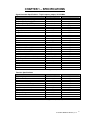
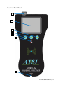
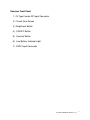
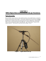
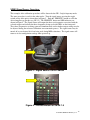
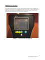
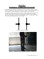
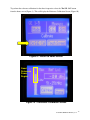
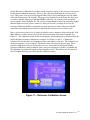
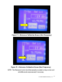
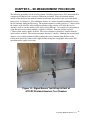
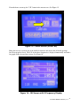
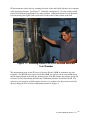
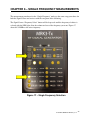
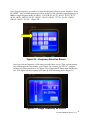
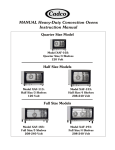
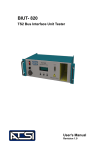
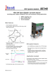
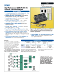
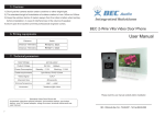
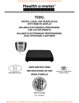
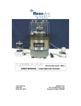
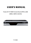
ATSI
Advanced Testing Services, Inc.
Products Division
9420 San Mateo Blvd. NE, Suite C, Albuquerque, NM 87113
MRK3
MRI RF Shielding Effectiveness
TEST KIT
OWNER/USER MANUAL
REV 1.2
ATSI
Ph: 505-292-2032
ATSI
Fax: 505-237-8430
TABLE OF CONTENTS
Chapter 1
Page
Specifications……………………………………………......
2
Signal Source Specifications……………………………….
2
Receiver Specifications……………………………………..
2
Antenna Specifications………………………………………
3
Chapter 2
MRK3 Front Panel Signal Source…………………………..
4
MRK3 Front Panel Receiver…………………………………
6
Chapter 3
MRK3 Signal Source and Receiver Set-up Procedures…
8
Chapter 4
MRK3 SE Reference Calibration Procedure……………..…
15
Chapter 5
MRK3 SE Measurement Procedure…………………....…….
20
Chapter 6
Single Frequency SE Measurement Procedure…….………
23
ATSI MRK3 OWNERS MANUAL_V1.2
1
CHAPTER 1 – SPECIFICATIONS
Signal Generator Specifications: Triple frequency output, 101.251MHz.
Parameter
Value
Frequency range
50 - 155
Frequency resolution
10
o
Frequency Calibration @ 25 C
+/- 1.0
o
o
Frequency Stability (0 -70 C)
+/- 1.0
Aging
+/- 1.0
SSB Phase Noise
@1kHz from carrier
@10kHz from carrier
@100kHz from carrier
Wideband noise
Output harmonics
Sub-harmonics
Non-harmonic spurious
30kHz < offset < 380 kHz
380kHz< offset < 1MHz
1MHz < offset < 2.5MHz
Wideband
Output power (500kHz - 400MHz)
Output impedance
DC input Voltage
DC input Current
MRK3-Tx
Size: 3.6" x 7.9" x 1.3"
Receiver Specifications:
Parameter
Frequency range
IF Bandwidth
Receiver sensitivity
SE measurement range
SE measurement accuracy
Input Power (max linear)
Input impedance
DC input Voltage
DC input Current
MRK3-Rx
Size: 4.9" x 9" x 2.0"
Unit
MHz
Hz
ppm
ppm
ppm/year
-107
-114
dBc/Hz
dBc/Hz
-122
<-130
dBc/Hz
dBc/Hz
-60
-75
dBc
dBc
-53 max
-47 max
-60 max
-70 max
dBc
dBc
dBc
dBc
12 +/- 1.5dB
50
dBm
Ohms
9-15
250
V
mA
Weight: 7.5 oz (no batteries)
Value
50 - 155
8
-135
0 - >110
+/-1.0
Unit
MHz
kHz
dBm
dB
dB
+5
50
dBm
Ohms
9-15
600
V
mA
Weight: 14 oz (no batteries)
ATSI MRK3 OWNERS MANUAL_V1.2
2
Antenna Specifications 2ea:
Parameter
Frequency range
Input impedance
Value
50 - 155
50
Unit
MHz
Ohms
ATSI MRK3 OWNERS MANUAL_V1.2
3
CHAPTER 2 – FRONT PANEL
Signal Source
Front Panel
1
2
3
4
5
8
6
7
ATSI MRK3 OWNERS MANUAL_V1.2
4
Signal Source Front Panel
1.) BNC Type Female RF Output Connector
2.) ON/OFF Toggle Switch
3.) 9VDC Input Connector
4.) Preset Mode Button
a. This button selects the triple preset frequencies for the
specified magnets. Each button push cycles to the next set of
preset magnet frequencies.
5.) Frequency Select Button
a. This button selects a single output frequency from the twenty
preset frequencies. Each button push cycles to the next preset
frequency.
6.) Hold Button
a. This button is currently NOT ACTIVE
7.) LED light indicating the ROW of the active frequency/frequencies.
8.) LED light indicating the COLUMN of the active
frequency/frequencies.
ATSI MRK3 OWNERS MANUAL_V1.2
5
Receiver Front Panel
1
2
3
4
5
6
7
ATSI MRK3 OWNERS MANUAL_V1.2
6
Receiver Front Panel
1.) N Type Female RF Input Connector
2.) Touch View Screen
3.) Brightness Button
4.) ON/OFF Button
5.) Contrast Button
6.) Low Battery Indicator Light
7.) 9VDC Input Connector
ATSI MRK3 OWNERS MANUAL_V1.2
7
Important Notes:
1. SE MEASUREMENTS:
THIS UNIT IS DESIGNED TO ONLY CONDUCT SE MEASUREMENTS
WITH THE SIGNAL SOURCE POSITIONED OUTSIDE OF THE SHIELDED
ENCLOSURE, AND THE RECEIVE SYSTEM INSIDE THE SHIELDED
ENCLOSURE. THE RECEIVER IS HIGHLY SENSITIVE, AND CAN BE
SATURATED FROM OUTSIDE AMBIENT RF SOURCES.
FOR SE MEASUREMENTS THE MRK3 TEST KIT SHOULD BE USED IN
THE CONFIGURATIONS SHOWN IN THE SET UP SECTION OF THIS
MANUAL. MODIFICATIONS SUCH AS SUCH AS IN-LINE AMPLIFIERS
OR ATTENUATORS SHOULD NOT BE USED.
2. RECEIVER WARM UP:
Software Version 2.5: Units with this software version have temperature
compensated power measurements and can be used after a 30 second warm
up. (This assumes ambient temperature operating range from 30ºF to 130ºF,
use in ambient temperatures below 30º may require longer warm up time.)
Software Version 2.3: Before the first use of the day, the receiver should
be turned on for 10-15 minutes and allowed to warm up to operating
temperature. The receiver may then be turned off and on without additional
warm up if not turned off for more than 20 minutes.
(Software version is displayed on the initial screen when receiver is
powered on.)
3. USING AC ADAPTERS: The AC adapters for the receiver and signal
generator are marked with RX and TX labels. AC power may be safely
used with rechargeable or alkaline AA batteries installed in the units. (The
batteries are NOT charged using the AC adapters)
4. CHARGING BATTERIES: The rechargeable batteries included in the test kit
should be removed from the units and charged with the supplied AA battery
charger upon receipt. Powering the signal source and receiver from the AC
adapter will not charge the installed batteries. Regular alkaline AA batteries
can also be used to power the units.
ATSI MRK3 OWNERS MANUAL_V1.2
8
5. LOW BATTERY INDICATOR: The low battery indicators will turn on when
batteries levels are getting low. The receiver and signal source can continue
to be used with low batteries but will turn off automatically once the battery
levels become to low to sustain operation within the performance
specifications.
6. SIGNAL SOURCE MODE FOR S.E. CALIBRATION: The Signal Source
should be left in the same mode while making S.E. measurements as used
during the S.E. reference level calibration. If the Signal Source was
outputting three frequencies during the S.E. calibration process, it should be
set to output the same three frequencies while making S.E. measurements.
The same is true when the Signal Source is set to output a single frequency.
The output mode needs to be maintained between S.E. calibration and S.E.
measurements to ensure the power level is the same during both the
calibration and measurement steps. The Signal Source will output a
different average power level in single frequency mode than at the same
frequency when the triple frequency output mode is used.
7. CHECKING S.E. MEASUREMENT RANGE: The S.E. measurement range can
be checked by turning off the Signal Source, and measuring S.E. inside the
shielded enclosure. Since the Signal Source is turned off, the receiver will
show the highest S.E. that can be achieved for the current calibration and
measurement setup. The S.E. currently being measured is limited by the
internal noise of the receiver and any interfering signals that may be present
inside the RF shielded room.
8. INCREASING S.E. MEASUREMENT RANGE: Using the Signal Source in
single frequency mode can increase the S.E. measurement range over what
can be achieved in triple frequency mode. Single frequency mode transmits
a higher average power level that will give a higher reference level during
the S.E. calibration step and give higher dynamic range during S.E.
measurements.
ATSI MRK3 OWNERS MANUAL_V1.2
9
CHAPTER 3
MRK3 Signal Source and Receiver Set-up Procedures
Signal Source Setup:
Remove Di-Pole antennas from case along with the elements and assemble them by screwing the
antenna elements into the antenna heads. Connect the signal generator side antenna to the tripod
using the threaded tripod mount. Fully extend tripod legs and raise tripod head. Strap the MRK3
Signal Source to a tripod leg with the velcro tether strap. Connect the RF output of the Signal
Source to the antenna with the supplied short RF cable. (No element tuning is required for the
supplied antennas). The transmit set-up should look like Figure 1 below.
Figure 1 – Signal Source Set-up
ATSI MRK3 OWNERS MANUAL_V1.2 10
Receiver Setup:
Connect the RF input of the MRK3 Receiver to the receive antenna with the long RF cable. (Rx
cable is labeled, and has ferrite suppression). Screw antenna elements into antenna head and
fully extend elements. (No element tuning is required for the supplied antennas). The receive
system should look like the set-up shown in Figure 2.
Figure 2 – Receive Set-up
ATSI MRK3 OWNERS MANUAL_V1.2 11
MRK3 Signal Source Operation:
This example of the calibration procedure will be shown for the GE 1.5 triple frequency mode.
The same procedure is used for the other modes. Turn the signal source on using the toggle
switch on top of the unit as shown here in Figure 3. Push the "PRESETS" button to select the
desired magnet type (In this case GE 1.5). The ‘PRESETS’ button and LED indicators are
shown in Figure 4. The Signal Source will output the three test frequencies associated with the
selected magnet and indicate the three frequencies being used with LED's on the front panel.
These three frequencies are being generated simultaneously and no further output settings need to
be adjusted during the reference calibration or measurement process. The signal source may be
turned off to save battery life if not being used during MRI evaluations. The signal source will
return to its last configuration settings when powered up.
Figure 3 – Signal Source On-Off Switch
Figure 4 – Presets Button set to GE 1.5
ATSI MRK3 OWNERS MANUAL_V1.2 12
The output frequencies for triple output mode are as follows:
GE 1.5
51.251 MHz , 63.751 MHz, 76.751 MHz
GE 3.0
102.251 MHz, 127.751 MHz, 153.251 MHz
All Others
64.251 MHz, 101.251 MHz, 128.251 MHz
ATSI MRK3 OWNERS MANUAL_V1.2 13
MRK3 Receiver Operation:
Setup MRK3 Signal Source and select the required transmit frequency mode according to the
instructions in the Signal Source Setup and Operation sections above. Setup the MRK receiver
according to the instructions in the MRK3 Receiver Setup section and turn on receiver by
pushing the center button below the screen as shown in Figure 5.
Figure 5 – ON-OFF Button for Receiver
ATSI MRK3 OWNERS MANUAL_V1.2 14
CHAPTER 4
REFERENCE CALIBRATION PROCEDURE
Before RF shielding effectiveness measurement can be taken, a reference calibration must be
performed with the system. The procedures for this are as follows. Place the Di-pole source and
receive antennas, oriented horizontally, in an open area with the receive antenna held
approximately 2 meters away from the source antenna. Ensure that the receive antennas is held
at about the same height above ground as the source antenna. Ensure there are no objects
between or around the two antennas that could significantly affect the strength of the RF signal.
The antenna orientation/positioning is shown in Figure 6.
6’
(Top view of antenna orientation)
Figure 6 – Antenna Positioning for Reference Calibration
ATSI MRK3 OWNERS MANUAL_V1.2 15
From the home screen (Figure 7) on the receiver unit, tap the "Mode" button. This will display
the mode selection screen (Figure 8).
Figure 7 – Home Screen
Select the button for the desired magnet type. This will set the three frequencies of operation for
the receiver.(This example will be for GE 1.5). Once the magnet is selected it will return to the
home screen (Figure 9).
Figure 8 – Magnet Selection Screen
ATSI MRK3 OWNERS MANUAL_V1.2 16
To perform the reference calibration for the three frequencies select the "Do S.E. Cal" button
from the home screen (Figure 9). This will display the Reference Calibration Screen (Figure 10).
Figure 9 – Return to Home Screen
Good
Reference
Power
Region
Figure 10 – Reference Calibration Screen
ATSI MRK3 OWNERS MANUAL_V1.2 17
On the Reference Calibration Screen there will be a numeric display of the reference level power
for the current calibration frequency. There is also a bar graph indicating the received power
level. This power level needs to be below the 'Max' line to avoid saturating the receiver which
will result in inaccurate S.E. readings. The power level should also not be below the 'Low' area
to ensure a dynamic range of greater than 100dB is achieved. An example of the acceptable
power region is shown in Figure 10. The receive antenna should be moved up and down slightly
until the highest received power is achieved. If the power level is too high or too low, the
reference calibration should be performed in a more open area to reduce reflection of the RF
signal from surrounding objects which can affect the received power level of the system.
Once a good receive power level is achieved, hold the receive antenna in place and tap the "Cal
Now" button to set the reference level for the S.E measurement at the active frequency. See
Figure 11. The calibration screen for the next frequency will automatically be displayed after the
current frequency reference calibration is complete. See Figure 12 and 13. Calibrate the
reference level for the other two frequencies in the same manner as the first. The calibration for
all three frequencies is now complete. The home screen will now be displayed again. These
reference calibration levels are stored in the receivers’ non-volatile memory until another
reference calibration is fully performed at this same preset frequency regardless of whether the
SE calibration is performed in single or triple frequency mode. The receiver may be turned on
and off without affecting any of the reference calibration values.
Figure 11 – Reference Calibration Screen
ATSI MRK3 OWNERS MANUAL_V1.2 18
Figure 12 – Reference Calibration Screen (Next Frequency)
Figure 13 – Reference Calibration Screen (Next Frequency)
NOTE: The Reference Levels should be manually recorded so they can be used
with dBm mode measurements if necessary.
ATSI MRK3 OWNERS MANUAL_V1.2 19
CHAPTER 5 – SE MEASUREMENT PROCEDURE
The following procedures can be used to perform a shielding effectiveness (S.E.) measurement in
a magnet mode that has had a reference calibration performed. Place the transmit antenna
outside of the shielded room with the elements horizontal and parallel to the wall of the shield
being tested. See Figure 14. The calibration distance of 2 meters should be maintained between
the two antennas during the SE testing. The transmit antenna is usually placed at 1.7 meters from
the surface of the shield to achieve uniform radiation of the exterior wall, while the receive
antenna is used to scan the interior of the wall to locate RF leaks. An example of a measurement
setup that meets most testing standards would be as follows: Transmit antenna is placed
1.7meters from outside surface of shield. The receive antenna is positioned .3meters from the
inside surface of shield. The total measurement distance is 2 meters. Although the measurement
distance is not exactly maintained while scanning the receive antenna from the floor to the
ceiling of the shield, the effect of this slight distance change has a negligible effect on the S.E.
measurement for single level rooms.
Figure 14 – Signal Source Test Set-up in front of
ATSI RF Shielded Anechoic Test Chamber
ATSI MRK3 OWNERS MANUAL_V1.2 20
From the home screen tap the "S.E." button in the measure area. See Figure 15.
Figure 15 – Home Screen (Select SE)
Bring the receiver system inside of the shielded enclosure and ensure that all shield openings
have been properly closed. The S.E. for the three frequencies is displayed numerically and with a
bar graph on the screen of the receiver. See Figure 16.
Figure 16 – SE Screen with 3 Frequency Display
ATSI MRK3 OWNERS MANUAL_V1.2 21
SE measurements can be taken by scanning the inside of the shield wall with the receive antenna
at the appropriate distance. See Figure 17. Normally a maximum 12’x12’ foot section of wall
can be tested with the Signal Source in a single position. Additional sections of wall should be
tested by moving the Signal Source and receiver to the center of that section of the wall.
Figure 17 – Scanning Inside of ATSI RF Shielded Anechoic
Test Chamber
The measurement range on the SE screen is between 50 and 110 dB of attenuation for each
frequency. For RF leaks that register lower than 50 dB, the receiver can be used in dBm mode
and the range adjusted to measure the absolute power of the RF leakage and compare it with the
reference level recorded during the Reference Calibration procedure to calculate the SE. The
reference level cannot be recalled from the receiver so it would need to have been recorded by
the user during the S.E. reference calibration procedure in Chapter 4.
ATSI MRK3 OWNERS MANUAL_V1.2 22
NOTES:
ATSI MRK3 OWNERS MANUAL_V1.2 23
CHAPTER 6 – SINGLE FREQUENCY MEASUREMENTS
The measurement procedures for the “Single Frequency” mode are the same setup procedures for
both the Signal Source and receiver with the exception of the following:
The Signal Source “Frequency Select” button will be depressed until the frequency of choice is
selected with the LED lights lit in the column and row of the frequency you want. Figure 17
shows 64.251MHz as the active frequency.
Figure 17 – Single Frequency Selection
ATSI MRK3 OWNERS MANUAL_V1.2 24
The receiver “Mode” button will be tapped when in the “Home Screen”. (Figure 18)
Figure 18 – Home Screen
Tap/select the “Single” button as shown in Figure 19. This will display the single frequencies
available for selection. (Figure 20)
Figure 19 – Mode Selection Screen
ATSI MRK3 OWNERS MANUAL_V1.2 25
Now select the frequency you wish to use from the frequency selection screen displayed. If you
hit “NEXT”, other available frequencies will be displayed. The selectable output frequencies in
MHz for single frequency mode are 50.251, 51.251, 60.251, 63.751, 64.251, 70.251, 76.751,
80.251, 90.251, 100.251, 101.251, 102.251, 110.251, 120.251, 127.751, 128.251, 130.251,
140.251, 150.251, 153.251. (Figure 20)
Figure 20 – Frequency Selection Screen
Once you select the frequency it will return you to the home screen. Then you can conduct
your calibration in the same manner as in Chapter 4 by selecting “Do SE Cal” , and then
conduct your SE measurement as in Chapter 5 by selecting the SE button from the Measure
area. The display for that frequency will come up in SE measuring mode. (Figure 21)
.
Figure 21 – Single Frequency SE Screen
ATSI MRK3 OWNERS MANUAL_V1.2 26
ATSI MRK3 OWNERS MANUAL_V1.2 27
(THIS PAGE LEFT INTENTIONALLY BLANK)
ATSI MRK3 OWNERS MANUAL_V1.2 28
ADVANCED TESTING SERVICES, INC.
9420 San Mateo Blvd. NE, Suite C
Albuquerque, New Mexico
87113
Phone: 505-292-2032
Fax: 505-237-8430
Website: www.advanced-testing.com
ATSI MRK3 OWNERS MANUAL_V1.2 29