1
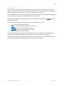
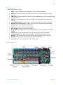
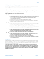
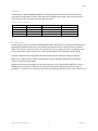
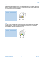
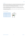
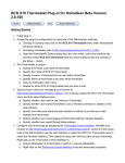
UniPi
technical
documentation
REV 1.1
UniPi
Contents
Overview.................................................................................................................................................. 2
Description .............................................................................................................................................. 3
GPIO port map ..................................................................................................................................... 4
Power Requirements ........................................................................................................................... 5
Connecting Raspberry Pi to UniPi........................................................................................................ 5
Building blocks ......................................................................................................................................... 5
Relays................................................................................................................................................... 5
Digital Inputs ....................................................................................................................................... 5
5-12V Step-up (internal 12V power supply) .................................................................................... 6
Jumper settings ............................................................................................................................... 6
Analog Inputs....................................................................................................................................... 6
EEPROM ............................................................................................................................................... 7
Analog Output ..................................................................................................................................... 7
1Wire sensors ...................................................................................................................................... 8
UART .................................................................................................................................................... 8
I2C ports ............................................................................................................................................... 9
Technical parameters ............................................................................................................................ 10
Onboard I2C ICs.................................................................................................................................. 10
Relays................................................................................................................................................. 10
Digital Inputs ..................................................................................................................................... 10
Analog Output ................................................................................................................................... 10
Power Requirements ......................................................................................................................... 10
Dimensions ........................................................................................................................................ 10
Revision History ..................................................................................................................................... 11
Changes ............................................................................................................................................. 11
WWW. UNIPI. TECHNOLOGY
1
REV 1.1
UniPi
Overview
UniPi is an add-on board for the Raspberry Pi (RPi). It features many components such as 12 (+2)
digital inputs with LED signalization, two 0-10V analog inputs, one 0-10V analog output, changeover
relays, single channel 1wire master controller and a real-time clock module.
The two digital inputs 13,14 and the I2C_0 bus are meant to connect via the P5 header of RPi B (only)
which is no longer available on newer Raspberry Pis (B+ and newer).
We provide basic open-source Python library for interfacing the UniPi available on GitHub which is
recommended to use.
There are also many platforms and libraries that are compatible with UniPi:
•
•
•
•
•
REX – Industrial PLC automation tool
FHEM – Home automation GNU/GPL v.2 Perl server
Wyliodrin – Online visual programming service
HomeSeer – Another home automation system
Others… See www.unipi.technology
UniPi is fully compatible with Raspberry Pi (models A, A+, B, B+, B+ model 2) and mounting-hole
compatible with BeagleBone Black. However we do not provide support for BeagleBone.
Please note the UniPi is only compatible with Raspberry Pi model B rev 2. Connecting model B rev. 1
is also possible provided checking the Raspberry Pi official documentation.
WWW. UNIPI. TECHNOLOGY
2
REV 1.1
UniPi
Description
Major building blocks of UniPi:
•
•
•
•
•
•
•
•
•
•
•
•
•
•
Relays: 8 relays 250VAC@5A or 24VDC@5A – control switching elements
UART port: Standard serial port to connect serial console or many other devices (NFC
readers, … )
1Wire port: Provides 1Wire bus interface to connect 1Wire devices such as temperature and
humidity sensors
I2C port: For connecting other extension modules for example relay or analog output
modules
I2C configuration pins: To connect the I2C_0 bus from the RPi (only for advanced users)
RTC (Real Time Clock) module: Provides real time in case of internet or power outage
(backup battery not included in the package).
Power 5V: 2.1mm connector for power supply
RPI connector: 26-pin connector for Raspberry Pi
Digital inputs: 12(+2) galvanically isolated digital inputs for reading signals from external
devices
12V out: Power supply 12V@200mA - only for use with digital inputs of the UniPi
Configurable ports: To configure digital inputs for use with external power source
Analog in: Two 0-10V analog inputs for reading analog signals from external devices
Analog out: One 0-10V analog output for proportional controlling
AO trimmer: For precise adjustment of the analog output
Figure 1 - The UniPi
WWW. UNIPI. TECHNOLOGY
3
REV 1.1
UniPi
GPIO port map
Table 1 – Raspberry Pi P1 header map
UniPi
AO
I01
I02
I03
I04
I05
I06
I07
I08
I09
I10
I11
I12
I2C1_SCL
I2C1_SDA
UART RX
UART TX
RPi BCM
GPIO18
GPIO04
GPIO17
GPIO27
GPIO23
GPIO22
GPIO24
GPIO11
GPIO07
GPIO08
GPIO09
GPIO25
GPIO10
GPIO02
GPIO03
GPIO15
GPIO14
Function
PWM
Digital Input
Digital Input
Digital Input
Digital Input
Digital Input
Digital Input
Digital Input
Digital Input
Digital Input
Digital Input
Digital Input
Digital Input
I2C1_SCL
I2C1_SDA
UART0_RXD
UART0_TXD
Description
Analog Output 0-10V
Digital Input
Digital Input
Digital Input
Digital Input
Digital Input
Digital Input
Digital Input
Digital Input
Digital Input
Digital Input
Digital Input
Digital Input
Internal I2C_1, RJ11 connector
UART RJ11 connector
Table 2 – Raspberry Pi P5 header map
UniPi
I13
I14
I2C0_SCL
I2C0_SDA
RPi BCM
GPIO31
GPIO30
GPIO29
GPIO28
Function
Digital Input
Digital Input
I2C0_SCL
I2C0_SDA
Description
Digital Input
Digital Input
External I2C_1
Table 3 – MCP23008 pin map
Relay
8
7
6
5
4
3
2
1
MCP23008
GP0
GP1
GP2
GP3
GP4
GP5
GP6
GP7
WWW. UNIPI. TECHNOLOGY
4
REV 1.1
UniPi
Power Requirements
There are two options of powering the UniPi board and Raspberry Pi:
• Single power source (RPi and UniPi are powered from the same power source)
• jumper JP1 mounted
• 5V DC 2A through the UniPi power connector (1.5A for UniPi + RPi requirements)
• Please note that UniPi can only provide 750mA to the RPi (max 1.1A in newest
versions of UniPi)
• Raspberry Pi micro USB power connector not used
• Dual power source (separate power source for each UniPi and Raspberry Pi)
• jumper JP1 dismounted
• Raspberry Pi powered from the micro USB port according to the RPi requirements
• 5V DC 1.5A through the UniPi power connector
Attention:
• Powering the UniPi from the Raspberry Pi is not recommended and could damage the
Raspberry Pi.
• When using the Raspberry Pi in heavy load and multiple peripherals connected we
recommend dual power source solution.
Connecting Raspberry Pi to UniPi
Before the first use plug in a CR2032 battery to the battery holder.
Connecting UniPi to Raspberry Pi is straight forward:
1.
2.
3.
4.
5.
6.
Make sure you have properly configured the power jumper – see powering requirements
Screw the spacers to the mounting holes of the UniPi
Connect the provided flat cable to the RPi connector
Screw the Raspberry Pi to the UniPi
Connect the other end of the flat cable to the RPi (make sure it is not twisted)
Plug in the power supply
Building blocks
Relays
Maximum relay switching power is limited to 250V AC/5A or 24V DC/5A, voltages over this limit must
be switched using external relay or contactor.
Relays are controller by the MCP23008 (address 0x20), see map of MCP’s GPIO to relays in Table 3 .
Each relay has a LED indicating its state.
There are three contacts for each relay named CO (change-over or C=connected), NO (normally
opened), NC (normally closed). By default contacts CO and NC are connected (NO is not connected),
by switching the relay on, CO gets connected to NO (NC is disconnected).
Digital Inputs
These inputs can be triggered by 5-24V DC voltage with minimum pulse length of 5ms. For easy visual
reading of their states all inputs are equipped with LED.
When using the GPIOs make sure to set a software pull-up resistor on each GPIO to make it work
properly otherwise state of the GPIO cannot be read properly.
WWW. UNIPI. TECHNOLOGY
5
REV 1.1
UniPi
5-12V Step-up (internal 12V power supply)
All inputs are primarily set to be driven by the internal 12V power supply. The 12V line is wired out
via the orange connector marked as 12V. Do not exceed 200ma current draw.
Jumper settings
In case of using external power source, inputs must be configured by JP2 - JP5 jumpers. The
configuration must be done before powering up the UniPi. Using the external power supply and
proper jumper configuration provides galvanic isolation for its inputs.
Jumper configuration when using external power source:
•
JP2
o
o
o
•
JP3
o
o
o
•
When switched to the side of the JP3 label, inputs I01 and I02 act as inputs for signal
from the connected peripheral device via the external power source.
The ground of power supply for this inputs must be connected to the P02.
Please note that to set I01 and I02 for ext. power source make sure to switch JP2 first
and then JP3, after that you can safely connect the peripheral device.
JP4
o
o
•
Switching this jumper to the side of the JP2 label causes the P02 (green connector) to
act as an input for ground from the external power source. Otherwise P02 is
connected to the internal 12V.
This step must be done as first when changing jumper settings.
Please note that after this step, the GND of UniPi is connected to P02! Make sure to
proceed with JP3 settings after this step.
When switched to the side of the JP4 label, inputs I03 and I04 act as inputs for signal
from the connected peripherals via the external power source.
The ground of power supply for this inputs must be connected to P01.
JP5
o
o
o
When switched to the side of the JP5 label, inputs I05 - I14 act as inputs for signal
from the connected peripherals via the external power source.
The ground of power supply for this inputs must be connected to P01.
Please note that I13 and I14 are wired out via the P5 header of Raspberry Pi (models
before the PLUS versions).
Analog Inputs
UniPi features two analog 0-10V input channels (via the MCP3422, address 0x68) marked as AI1 and
AI2. Each channel has its own + and – (e.g. AI1+ and AI1-). The + connector expects positive voltage
from the connected device and – expects the negative pole (the GND). The guaranteed accuracy is
5% however 1% is commonly reachable.
To correctly calculate the input voltage, a coefficient of the resistor divider has to be taken into
account. The coefficient of each channel is saved in EEPROM as single precision binary floating point
format binary32 (IEEE 754). Before version 1.1 the coefficient is not saved in the EEPROM and thus
must be calculated during conversion in software (Typically the value is around 5.56). See chapter
EEPROM for more details. 1
WWW. UNIPI. TECHNOLOGY
6
REV 1.1
UniPi
EEPROM
UniPi features onboard EEPROM (24C02) for storing important information with 2k bit memory
organized into single block of 256 * 8-bit. We reserve address space 0xe0 – 0xff the rest is left for
user space. The rest of unused reserved bytes are nulled.1
Table 4 - memory organization
Starting address
0xe0
0xe2
0xf0
0xf4
Number of bytes
2
2
4
4
Example
fa-55
1.1
0x40b089c5 (5.516818)
0x40b08b44 (5.517)
Description
UniPi identification
UniPi version
AI1 coefficient
AI2 coefficient
Analog Output
Analog output is driven by the GPIO 18 PWM signal and is designed to run at 400Hz. The GPIO port is
galvanically isolated from the rest of the output. The maximum current driven from this output is
20mA. This output is meant to control 3rd party devices that can adjust its power according to the 010V. The precision of AO in UniPi v1.0 is +-5% but also depends of the Raspberry Pi CPU usage.
External voltage must be connected to the AOV connector with maximum voltage of 35V DC.
Make sure to adjust output voltage using the blue trimmer (labeled as R49) before connecting
devices to avoid causing damage.
Behavior of the AO has changed since the UniPi version 1.1 (incl.). Before that 100% duty cycle on
PWM meant to output 0V, and 0% DC (or permanent low) meant 10V. But after the version 1.1
(including v 1.1) the process is different and more logic meaning 100% duty cycle is 10V and 0% is 0V.
1
WWW. UNIPI. TECHNOLOGY
7
REV 1.1
UniPi
1Wire sensors
UniPi features single channel 1Wire master controller (DS2482-100, address 0x18). The 1Wire bus is
wired out via the RJ45 connector (see Table 5 for detailed description). The data line is ESD protected
and the 5V power current is limited to 200mA.
Table 5 - 1Wire RJ45 connector
RJ11 pin
1
2
3
4
5
6
7
8
Function
5V
DATA
DATA
GND
UART
The UART interface of Raspberry Pi is wired out via the RJ11 connector labeled UART. See Table 6 UART RJ11 connector. This port does not have any protection, so make sure to be careful when
connecting devices. Operating voltage of this port is 3V3.
Table 6 - UART RJ11 connector
RJ11 pin
1
2
3
4
5
6
Function
5V
RX
TX
GND
-
WWW. UNIPI. TECHNOLOGY
8
REV 1.1
UniPi
I2C ports
Raspberry Pi has two I2C interfaces. The I2C _1 of the RPi is connected via the main P1 connector and
does not need any special modification. All the onboard ICs are connected to this bus. The second I2C
bus, I2C_0, is wired out via the P5 connector which needs to be soldered from the bottom of the
Raspberry Pi. Please check our online tutorial for further information.
The I2C _1 is by default wired out via the onboard RJ11 connector labeled I2C and features ESD
protection. UniPi also features optional I2C port (labeled I2C_1) on the edge of the board but does
not have any connector by default.
Please note that the I2C_0 has been reserved for special purpose starting with RPi models + and thus
is no longer recommended to use.1
Table 7 - I2C RJ11 connector
RJ11 pin
1
2
3
4
5
6
Function
5V
I2C data (SDA)
I2C clock (SCL)
GND
-
WWW. UNIPI. TECHNOLOGY
9
REV 1.1
UniPi
Technical parameters
Onboard I2C ICs
All onboard I2C chips are connected to the main bus.
Table 8 - I2C chip addresses
Chip type
MCP23008
DS2482-100
MCP79410
MCP3422
24AA00/24C02
Address
0x20
0x18
0x6F, 0x57
0x68
0x50-0x57
Usage
Relays
1Wire master
Real Time Clock
ADC
EEPROM
Relays
•
•
Version 1.0: 8x Omron G5LA-1-E: 250V AC/5A or 24V DC/5A
Version 1.1: 8x Finder 36.11.9.005.4001
Digital Inputs
•
12(+2)x 5-24V DC
Analog Output
•
•
Maximum supply voltage: 35V
Maximum output current: 20mA
Power Requirements
•
•
•
The main UniPi power connector is standard 2.1mm inner diameter, 5.5mm outer diameter
5V DC 2A in single power supply mode (JP1 connected)
o Attention: UniPi can supply only 750mA (1.1A in newest version) to the RPi
When JP1 disconnected
o 5V DC 1.5A for UniPi
o 5V DC min 1A for Raspberry Pi (according to the RPi manual)
Dimensions
Width: 198mm
Height: 86mm
Depth: 16mm (without the RPi, cable and spacers)
Weight: 0.21kg
WWW. UNIPI. TECHNOLOGY
10
REV 1.1
UniPi
Revision History
Revision Release date Author
1.0
6. 11. 2014
Tomas Hora
1.1
4. 3. 2015
Tomas Hora & Imas NV
Changes
1
Introduced in version 1.1
Thanks to Imas NV, Turnhout, Belgium for correction.
Raspberry Pi is a trademark of the Raspberry Pi Foundation.
WWW. UNIPI. TECHNOLOGY
11
REV 1.1