1
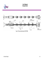
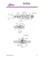
Unit 17 Denmore Industrial Estate, Denmore Road, Bridge of Don, Aberdeen AB23 8JW
User Manual
Grease Head
This Manual Covers the Following Part Numbers:
145-3297-HV0
145-3727-HV0
OPS-3297 Rev D
User Manual
Grease Head
Table of Contents
Revision History .......................................................................................... iii
Safety.............................................................................................................. iv
1 Introduction ............................................................................................... 1
1.1
General .............................................................................................. 1
1.2
Product Identification ......................................................................... 1
2 Technical Specification ............................................................................. 2
3 Technical .................................................................................................. 3
3.1
Description......................................................................................... 3
3.2
Key Product Features ........................................................................ 5
4 Operation .................................................................................................. 9
4.1
Lifting and Handling ........................................................................... 9
4.2
Pre Job .............................................................................................. 9
4.3
During Job ......................................................................................... 9
4.4
Post Job........................................................................................... 13
5 Maintenance ........................................................................................... 13
5.1
Introduction ...................................................................................... 13
5.2
Schedule.......................................................................................... 13
5.3
Safety .............................................................................................. 14
5.4
Tools ................................................................................................ 14
5.5
Redress Procedure .......................................................................... 15
5.6
Maintenance Record Sheet ............................................................. 16
6 Testing .................................................................................................... 17
7 Parts List and Drawings .......................................................................... 18
8 Spares .................................................................................................... 28
Table 1:Technical Data .................................................................................... 2
Table 2: Flow Tube Requirements ................................................................... 4
Table 3: Configuring to suit the wire............................................................... 11
Table 4: Maintenance Record ........................................................................ 16
Table 5: Parts List 145-3297-HH0.................................................................. 19
Table 6: Parts List 145-3727-HV0 .................................................................. 24
Table 7 : Redress Kit Part No RDK-3297-HV0 .............................................. 28
Table 8: Redress Kit Pt No RDK-3727-HV0 ................................................... 28
Table 9 : Supporting Equipment..................................................................... 29
Figure 1: Grease Head Safety ........................................................................ iv
Figure 2: Grease Head .................................................................................... 2
Figure 3: Pressure gradient inside the flow tube assembly .............................. 3
Figure 4: Couettes flow equation ..................................................................... 4
Figure 5: Fast Collar ........................................................................................ 5
Figure 6: Dual Port Connector Sub .................................................................. 5
Figure 7: Tension Pack Off .............................................................................. 6
Figure 8: Air Line Wiper Setup ......................................................................... 7
Figure 9: Lower Pack off (Option) .................................................................... 8
OPS-3297 Rev D
i
User Manual
Grease Head
Figure 10: Tie-off Hook .................................................................................... 8
Figure 11: Greasehead Setup ........................................................................ 12
Figure 12: Grease Head Assembly 145-3297-HH0........................................ 20
Figure 13: Grease Head Detail Assembly 145-3297-HH0 ............................. 22
Figure 14: Greasehead Assembly Pt No 145-3727-HV0 ............................... 25
Figure 15: Greasehead Detail Assembly Pt No 145-3727-HV0 ..................... 27
OPS-3297 Rev D
ii
User Manual
Grease Head
Revision History
Issue, Release Date
Rev A, 20 Apr. 10
Rev B, 12 Sept 10
Rev C, 14 Oct 10
Rev D, 03 Dec 10
OPS-3297 Rev D
Description
Initial Issue
Addition of GIH Pt No 145-3727 HV0
Update of Configuration Information
Pt No Update for Packing Gland
iii
User Manual
Grease Head
Safety
WARNING: Trapped air requires considerable time to compress and
when it is compressed is highly dangerous. It has enough stored
energy to separate parts with considerable force.
All pressure equipment has a particular pressure rating and care must be
taken to ensure that no item is used in a situation that may cause its working
pressure to be exceeded.
All personnel involved in pressure testing must be formally trained, competent
and utilising the appropriate PPE.
Safe-Lok devices, where fitted, should be checked for positional security to
avoid unnecessary movement of the collar
Ensure the identification band/plate is fitted and is displaying the correct
information as per the Tag Sheet/Index
This equipment and the equipment it is attached to is heavy never position
yourself below a suspended load
Figure 1: Grease Head Safety
Finger, Glove and
loose clothing trap
area
OPS-3297 Rev D
iv
User Manual
Grease Head
1 Introduction
1.1 General
Phuel has transformed the greasehead functionality with the innovation of
using what are essentially small quick union connections on the flow tube
housings. This vastly improves, eases and speeds up the redressing
operations and allows the operator to align his hydraulic connection with ease.
The design utilises standard flow tubes and comes complete with ball check
valves and chemical injection facilities. The Phuel greasehead is designed for
up to 10,000psi working pressure, 15,000psi test pressure H2S service.
Higher working pressures can be obtained if required
This user manual serves as an introduction to the equipment and contains the
relevant specifications, operation, planning and maintenance instructions,
parts list and drawings.
1.2 Product Identification
Phuel products are identified by a unique serial number that facilitates full
product traceability. Each product is supplied with a documentation pack that
contains product certification and material/inspection reports. The serial
number is always etched on the surface of the product but can sometimes be
difficult to find or read after painting. A customer identification number is also
included to allow the customer to track the asset in their system.
A stainless steel band secures the nameplate tag that is stamped with the
information shown below. This tag should be located in the first instance to
ensure that this manual refers to the correct equipment.
PHUEL OIL TOOLS LTD
DESCRIPTION & SIZE
CUSTOMER ID No
PHUEL ID No 06-XXX-XX
MWP & SERVICE
TEST DATE
OPS-3297 Rev D
1
User Manual
Grease Head
2 Technical Specification
Part Number
Connections
145-3297-HH0
145-3727-HV0
5 ¾’’ Otis Type
2’’ NPT Male Top Thread
10,000 Psi
15,000 Psi
H2S
318 lbs / 144 kg
133.3’’ / 3.39m
129.4’’ / 3.29m
Maximum Working Pressure
Design Test Pressure
Service
Weight
Overall Length (A)
Make Up Length (B)
Table 1:Technical Data
Figure 2: Grease Head
OPS-3297 Rev D
2
User Manual
Greasehead
3 Technical
3.1 Description
The grease injection control head (greasehead) provides a pressure seal
around stationary or moving wireline that is run into or out of wells to prevent
the escape of well fluids to the environment. The assembly consists of a
hydraulic pack off and a series of flow tube assemblies.
The flow tube assembly consists of a number of close fitting steel tubes
through which the wire line passes. Each flow tube is approximately 14” long
and these are slipped onto the wire and connected together with the fast collar
connection to build up the required length. Viscous grease is injected between
the bore of the flow tube and the outside of the wire and travels along the
length of the flow tube stack creating a pressure drop. Grease injection
pressure can then be increased to about 25% more than the well pressure to
create a liquid seal that allows the wire to move but prevents the escape of
well fluids. The inside diameter of the flow tubes needs to be from 0.003” to
0.008” larger than the actual wire diameter for the seal to be effective so the
flow tubes must be selected based on the wire being used.
Figure 3: Pressure gradient inside the flow tube assembly
The length of flow tube required depends on the well pressure, the wire size,
the flow tube size, the grease viscosity and pump rate and the effectiveness of
the seal will depend on the pull out speed of the wire. The relationship for the
pressure drop can be expressed mathematically by Couettes flow equation.
This shows that the clearance between the wire and the flow tube has a great
OPS-3297 Rev D
3
User Manual
Greasehead
effect on the pressure drop created as so this is the most important parameter
to consider.
Figure 4: Couettes flow equation
The actual diameter of the wire must be measured and recorded to allow the
correct diameter of flow tube to be selected. The condition of the wire must
also be considered as mud or rust ingress can cause the wire to swell.
Consideration also needs to be given to the wear of the flow tubes as these
tend to wear in the middle, where it is most difficult to measure the bore.
The grease is injected above the first flow tube and exits after the last one.
Since the grease is continuously moving and some is being lost to the well,
the injection process is continuous and in order to create sufficient flow rate it
may be necessary to inject at two locations depending on the well pressure.
The table below shows the recommended greasehead arrangement
depending on the well pressures. This is a guideline only.
Well Pressure
Fluid
No of flow tubes* No of Injection Points
0-5000 psi
Liquid
4
1
0-5000 psi
Gas
5
1
5-10,000 psi
Liquid
6
1
5-10,000 psi
Gas
7-8
1
10-15,000 psi
Liquid
10
2
10-15,000 psi
Gas
11-12
2
* including the flow tubes below the grease injection port(s)
Table 2: Flow Tube Requirements
OPS-3297 Rev D
4
User Manual
Greasehead
3.2 Key Product Features
3.2.1 Fast Collar
The fast collar is designed to allow quick replacement of the flow tubes either
due to a requirement for a line size change or for repair. The fast collar is
released by unscrewing the collar from the connector sub, which bears
against the circlip to pull the seal out of the bore - allowing access to the flow
tube housing and the flow tube. This results in a fast and easy method of
configuring the greasehead and allows the injection and return ports to be
orientated as required.
Figure 5: Fast Collar
3.2.2 Dual Ported Connector Sub
The Connector Subs between each of the flow tube housings has two
opposing saver sub ports. Depending on the Saver Sub fitted these can either
be blanked off or used for pressure monitoring in between each flow tube if
required. This provides maximum
operational flexibility
3.2.3 Check Valve Saver Sub
The saver sub interface also allows a right
angled check valve assembly to be used
that angles the outlet at a suitable angle
to ease the management of the hoses and
provides a check valve to prevent well
fluids being returned to the grease skid.
These subs can be placed in any location
but are normally used in the chemical
injection port and the grease injection
port.
Figure 6: Dual Port Connector Sub
The check valve components can easily be removed to provide a simple right
angled port that may be used on the grease return line if only one injection
line is required.
OPS-3297 Rev D
5
User Manual
Greasehead
3.2.4 Tension Pack off
The pack off assembly allows a rubber seal to be made against static wire in
order to prevent the escape of well fluids if the grease seal is lost. In some
greaseheads the packing can become energised by the flow of the grease
and can cause it to grip down on the wire and prevent or restrict the running of
the wire. The Phuel pack off element is located at both ends and is held in
tension to prevent this kind of problem from occurring.
Figure 7: Tension Pack Off
3.2.5 Air Line Wiper
The Phuel Air Line Wiper allows easier handling and wire protection due to
the smaller bell housing and its internal curvature. With a standard airline
connected the internal jet system produces a curtain of air which retains the
grease and wipes the wire removing almost 100% of the grease. The bell
housing also contains a drain hole which is usually plugged but is available to
be used to drain off any residual grease.
OPS-3297 Rev D
6
User Manual
Greasehead
Figure 8: Air Line Wiper Setup
OPS-3297 Rev D
7
User Manual
Greasehead
3.2.6 Lower Pack off Option
As an option there is a lower pack off assembly that can be attached below
the lower flow tube to provide a lower pack off assembly. This can be used to
quickly re-establish the grease seal during operations rather than circulating
the grease all the way to the BOP.
The lower pack off would be closed with the upper one and grease circulated
through only the greasehead length without any losses in to well below. This
will provide a smaller volume for circulation and may eliminate the need to
close BOP on the wire – thus saving valuable operational time.
Figure 9: Lower Pack off (Option)
3.2.7 Hose Tie-off Hook
A tie-off hook is provided in the bottom sub to allow the hoses that hang from
the greasehead to be secured and tied together. This improves the hose
management when lifting the greasehead into position.
This hook is not intended to be used for the lifting the greasehead. Do not
apply lifting loads at this point.
Figure 10: Tie-off Hook
OPS-3297 Rev D
8
User Manual
Greasehead
4 Operation
All operations to be carried out by suitably qualified and competent
personnel
4.1 Lifting and Handling
Thread protectors should always be fitted when lifting or moving the
greasehead.
4.1.1 Vertical
The greasehead should be lifted with a suitable lifting clamp or sling that is
rated for the total lifting load. Following the instructions for the clamp or sling
being used.
If practical leave the thread protectors fitted until ready to make up the
connections.
4.1.2 Horizontal
Suitable slings can be wrapped around either end of the greasehead to allow
horizontal lifting for means of transportation or fitting. Always pay attention to
the centre of gravity and do not continue to lift if the greasehead is not sitting
horizontal as it might slip through the slings.
4.2 Pre Job
•
•
•
•
•
•
•
•
•
Ensure thread protectors are fitted
Check maintenance record sheet and ensure the equipment has been
maintained by competent personnel
Check all certification is in date
Confirm information band is fitted and correct
Ensure equipment is suitable for the maximum working pressures and
services involved
Ensure visible ‘O’ rings are seated correctly and there are no signs of
damage
Ensure threads are clean
Inspect for signs of damage
Pressure test to maximum operating pressure
4.3 During Job
•
•
•
Select the correct size of flow tubes according to the actual wire sizes
for the wire being used.
Insert the wire as shown in the following diagram
Rig up the hoses according to the diagram
OPS-3297 Rev D
9
User Manual
Greasehead
4.3.1 Replacing the Saver Sub
It is not expected that the saver sub would need to be replaced during normal
operations but if damage occurs to a pressure fitting or a leak is found during
pressure testing then this procedure should be followed.
•
•
•
•
•
•
•
•
•
•
•
Ensure that the pressure is bled off.
Do not remove the pressure fittings at this time as they can be used to
provide grip to remove the plug.
Remove the two socket head cap screws and lock washers. (If they
appear unusually tight or difficult to move re-check that the pressure
has been removed).
Grip the pressure fitting and pull out the saver sub with a pulling and
rocking motion. If the pressure fitting has been removed already then
two ¼-20 UNC screws (not supplied) can be used to jack out the sub.
Inspect the o-ring for signs of damage and replace if necessary
Inspect the seal bore for signs of damage and report if necessary
If required, remove the pressure fitting – clean and inspect the pressure
port.
To re-fit the sub apply grease to the o-ring and seal bore.
Push the sub into the bore by hand as far as possible, ensuring that the
part is centralised in the bore.
Fit the screws and washers and tighten to drive the o-ring into the bore.
Make up each screw equally to ensure that the sub does not become
twisted.
Fully tighten the screws.
4.3.2 Removing the Check Valve Components
This will be required if the injection Check Valve Saver Sub is being moved to
the return port to provide a right angled port. The check valve can be reinstated by following the procedure in reverse.
•
•
•
•
•
With the check valve sub removed from the body
Unscrew the Hollow Hex Plug using a suitable hex key
Remove the spring and check valve and store in a safe place
Replace the Hollow Hex Plug to act as a thread protector
Refit the Check Valve sub to the required port.
4.3.3 Configuring to suit the wire
The Phuel greasehead is multi-line and so no special parts changes are
required to suit the diameter of the wire being used. Only the line wiper
module needs to be changes to ensure that the wiper works effectively.
The table below shows the parts that should be fitted for the range of wire
sizes.
OPS-3297 Rev D
10
User Manual
Greasehead
Wire
Interlocking
Seats
Split Packing
Packing Gland
Air Nozzle
Wire Guide
Line Wiper
Packing Stick
Item No *
20
21
40
55
57
59
Qty
1 off each
2 off each
1 off set
1 off
2 off each
2 off each
3/16
147-3361-W19
147-3365-W19
7/32
147-3361-W21
147-3365-W21
147-3361-W25
147-3365-W25
147-3361-W31
147-3365-W31
147-3361-W38
147-3365-W38
1/4
5/16
145-3236-W43
(LEFT)
&
145-3237-W43
(RIGHT)
147-3464-W31
145-2970-W43
145-2969-PU8
3/8
147-3464-W43
7/16
15/32
145-3236-W47
145-2970-W47
147-3361-W43
147-3365-W43
147-3361-W47
147-3365-W47
147-3464-W47
* - Refers to drawing shown in Section 7.
Table 3: Configuring to suit the wire
OPS-3297 Rev D
11
User Manual
Greasehead
Figure 11: Greasehead Setup
OPS-3297 Rev D
12
User Manual
Grease Head
4.4 Post Job
•
•
•
Inspect for signs of damage
Ensure threads are clean
Ensure thread protectors are fitted
5 Maintenance
All maintenance to be carried out by suitably qualified and competent
personnel
5.1 Introduction
Regular maintenance of the equipment using Phuel redress kits or Phuel
approved parts is essential to its continued safe operation. Ensure that the pre
and post job operating procedures are followed and that maintenance records
are kept.
5.2 Schedule
The maintenance schedule may be governed by international or company
standards and the following is considered to be the minimum requirements.
5.2.1 Pre & Post Job
Refer to Section 4.2 and Section Error! Reference source not found. for
details
5.2.2 Yearly
•
•
•
•
•
•
•
•
Disassemble Greasehead (see 5.5.1) clean and degrease all
components
Inspect the condition of all sealing surfaces and surface coatings
Re-coat threads and sealing surfaces if necessary. If in doubt contact
Phuel Oil Tools Ltd
Replace all elastomeric seals with items from redress kit (see spares
Table 7)
Regrease components
Re-assemble (see 5.5.2)
Pressure test to maximum working pressure in accordance to testing
procedure (see 6)
Inspect paint work and repair as necessary
5.2.3 Five Yearly
•
•
•
Yearly Maintenance (plus the following)
Carry out 100% surface NDE on all surfaces
Pressure test to test pressure witnessed by certifying authority
OPS-3297 Rev D
13
User Manual
Grease Head
5.3 Safety
•
•
•
•
•
Ensure all pressure testing is carried out in the appropriate testing area
by suitably qualified personnel.
Wear appropriate personal protective equipment.
Do not over exert yourself while using torque wrenches. Use
appropriate mechanical advantages when available.
Ensure that all tools and equipment are in good condition and are
suitable for the intended use.
Clear up any fluid spills immediately to avoid slips.
5.4 Tools
The following tools are required:
• Memac Chain Wrench (No2 with 14’’ chain)
Other pipe wrenches may be used but will mark equipment
• 3/8 hex Allen key
• 7/8’’ Spanner (If NPT Plug to be fitted)
• Wire Brush
OPS-3297 Rev D
14
User Manual
Grease Head
5.5 Redress Procedure
5.5.1 Dis-Assembly
•
•
•
•
•
•
•
•
•
Remove the packoff assembly by unscrewing the uppermost Fast
Collar (6)
Remove the Top Sub (1) and strip off the Saver Sub assembly
Pump up the piston and remove the Interlocking seats (20 & 21)
Remove the split Packing (22) and Packing Gland (40)
Bleed off the piston pressure and disconnect the pump
Remove the Seal Housing (2) and collect the spilled hydraulic fluid
Remove the Spring (41)
Remove the Piston (4)
Remove all the Saver Sub assemblies from the Return Housing
•
•
•
•
•
Remove the Flow Tube Housing (7) from the next Connector Sub (5)
Strip off the Saver Sub assemblies from the Connector Sub
Remove the Flow Tube if fitted
Remove the Circlip (43) and remove the Fast Collar (6)
Repeat this process until all Housings are removed
•
•
•
•
Remove the Check valve port from the Bottom Sub
Remove the Collar
Remove the Retaining Ring (24), Ball Cup (25) and Ball (42)
Remove the Check Valve Seat (23)
•
Remove all seals from the individual components without damaging the
surface of the sealing groove. Only do this if new seals are being fitted
– otherwise leave the seals as they are and inspect for signs of
damage or wear.
5.5.2 Re-Assembly
Re-assembly is the reverse to dis-assembly
•
•
•
Ensure fresh seals are used from a redress kit and verify that the expiry
date has not been exceeded
Inspect all seal grooves and bores for signs of scratches. Clean up if
required with fine emery cloth
Fit the seals avoiding excessive stretch and lightly coat with grease
OPS-3297 Rev D
15
User Manual
Grease Head
5.6 Maintenance Record Sheet
Date
Type of
Performed
Performed Maintenance
By
Verified
By
Comments
Table 4: Maintenance Record
OPS-3297 Rev D
16
User Manual
Grease Head
6 Testing
All testing is to be carried out in the designated test area and by suitably
qualified and competent personnel.
WARNING: Trapped air requires considerable time to compress and
when it is compressed is highly dangerous. It has enough stored
energy to separate parts with considerable force.
•
•
•
•
•
•
•
•
Fit appropriate test caps and blanking plugs. No flow tubes are required
for a body test
Fill with testing fluid bleeding off any air within the system
Apply a pressure of 500 psi and ensure pressure holds for a minimum
of 10 minutes
Increase pressure to 10,000 psi (Maximum Working Pressure), allow to
stabilise and maintain this pressure until it is evident there are no
apparent leaks. (Testing to be carried out to Test pressure when
decreed by maintenance schedule)
Bleed off pressure, drain test fluid and dry
Remove test caps
Apply coating of de-watering solution to protect the bore and threads
Fit thread protectors and shipping cap plugs
On completion of all maintenance ensure the maintenance record sheet (Para
5.6) is completed
OPS-3297 Rev D
17
User Manual
Grease Head
7 Parts List and Drawings
Item Number
1
2
3
4
5
6
7
8
9
10
11
12
13
20
21
22
23
24
25
29
30
31
32
33
34
35
36
37
40
41
42
43
44
45
46
47
48
49
50
55
56
57
Part Number
147-3363-480
145-2971-480
145-2974-480
145-2966-480
145-2975-480
145-2120-480
145-2121-480
145-2123-480
175-3341-480
145-2176-480
205-2105-480
900-3019-480
145-3248-480
145-3236-W43
145-3237-W43
145-2969-PU8
145-2126-B21
145-2128-B21
145-2127-PTF
802-2977-H80
802-2183-H80
801-0119-V90
801-0210-V90
801-0223-V90
801-0224-V90
801-0225-V90
801-0234-V90
801-0342-V90
145-2970-W43
145-2177-STL
145-2181-316
145-2180-STL
190-1749-STL
190-2786-PEK
190-1703-STL
SHC-0583-3A4
WNL-0580-304
950-3524-STL
145-2215-304
147-3361-W31
147-3362-480
147-3365-W31
OPS-3297 Rev D
Quantity
1
1
1
1
5
6
6
1
1
6
5
3
1
1
1
2
1
1
1
2
1
15
12
6
6
2
1
1
1
1
1
6
3
3
3
30
30
1
6
1
1
1
Description
LINE WIPER HOUSING
SEAL HOUSING
RETURN HOUSING
PISTON
CONNECTOR SUB
FAST COLLAR
FLOW TUBE HOUSING
BOTTOM SUB
5-3/4 SOLID COLLAR (DW STYLE)
SAVER SUB 1/2" NPT
BLANK TEST PORT
CHECK HOUSING
SAVER SUB (10MM HOLE)
INTERLOCKING SEAT - LEFT
INTERLOCKING SEAT - RIGHT
SPLIT PACKING
CHECK VALVE SEAT
RETAINING RING
BALL CUP
PISTON T-SEAL (2.00)
PISTON T-SEAL (3.250)
O-Ring - B.S Size 119
O-Ring - B.S Size 210
O-Ring - B.S Size 223
O-Ring - B.S Size 224
O-Ring - B.S Size 225
O-Ring - B.S Size 234
O-Ring - B.S Size 342
PACKING GLAND
PISTON SPRING
BALL BEARING 0.750 DIA
EXTERNAL CIRCLIP (DSH-50)
COMP SPRING (C6615650)
CHECK CONE SEAL
Hollow Lock Screw 3/4-16 (MAC-765)
Soc Hd Cap Size 1/2 Length 0.75 in
WASHER NORDLOCK (M12)
SHOULDER EYE BOLT (1/2 UNC)
SPLIT COTTER PIN 1/8 X 3" LONG
AIR NOZZLE (DW STYLE)
PACKING HOUSING
WIRE GUIDE (DW LINE WIPER)
18
User Manual
Grease Head
Item Number
58
59
61
62
63
100
Part Number
147-3364-316
147-3464-W31
SHC-0502-3A4
801-0220-V90
WNL-0500-304
910-3541-N66
Quantity
1
1
2
1
2
1
Description
FUNNEL (DW STYLE)
LINE-WIPER PACKING STICK
Soc Hd Cap Size 1/4 Length 0.375 in
O-Ring - B.S Size 220
Nordlock Washer size 1/4
DW MALE PROTECTOR 5-3/4
Table 5: Parts List 145-3297-HH0
OPS-3297 Rev D
19
User Manual
Grease Head
Figure 12: Grease Head Assembly 145-3297-HH0
OPS-3297 Rev D
20
User Manual
Grease Head
OPS-3297 Rev D
21
User Manual
Grease Head
Figure 13: Grease Head Detail Assembly 145-3297-HH0
OPS-3297 Rev D
22
User Manual
Grease Head
Item Number
1
2
3
4
5
6
7
8
9
10
11
12
13
20
21
22
23
24
25
29
30
31
32
33
34
35
36
37
40
41
42
43
44
45
46
47
48
49
50
55
56
57
Part Number
147-3363-480
145-2971-480
145-2974-480
145-2966-480
145-2975-480
145-2120-480
145-2121-480
145-2123-480
175-3341-480
145-2176-480
145-3665-480
900-3019-480
145-3248-480
145-3236-W43
145-3237-W43
145-2969-PU8
145-2126-B21
145-2128-B21
145-2127-PTF
802-2977-H80
802-2183-H80
801-0119-V90
801-0210-V90
801-0223-V90
801-0224-V90
801-0225-V90
801-0234-V90
801-0342-V90
145-2970-W43
145-2177-STL
145-2181-316
145-2180-STL
190-1749-STL
190-2786-PEK
190-1703-STL
SHC-0583-3A4
WNL-0580-304
950-3524-STL
145-2215-304
147-3361-W21
147-3362-480
147-3365-W21
OPS-3297 Rev D
Quantity
1
1
1
1
2
6
6
1
1
5
3
3
1
1
1
2
1
1
1
2
1
9
12
6
6
2
1
1
1
1
1
6
3
3
3
18
18
1
6
1
1
1
Description
LINE WIPER HOUSING
SEAL HOUSING
RETURN HOUSING
PISTON
CONNECTOR SUB
FAST COLLAR
FLOW TUBE HOUSING
BOTTOM SUB
5-3/4 SOLID COLLAR (DW STYLE)
SAVER SUB 1/2" NPT
BLANK CONNECTOR SUB
CHECK HOUSING
SAVER SUB (10MM HOLE)
INTERLOCKING SEAT - LEFT
INTERLOCKING SEAT - RIGHT
SPLIT PACKING
CHECK VALVE SEAT
RETAINING RING
BALL CUP
PISTON T-SEAL (2.00)
PISTON T-SEAL (3.250)
O-Ring - B.S Size 119
O-Ring - B.S Size 210
O-Ring - B.S Size 223
O-Ring - B.S Size 224
O-Ring - B.S Size 225
O-Ring - B.S Size 234
O-Ring - B.S Size 342
PACKING GLAND
PISTON SPRING
BALL BEARING 0.750 DIA
EXTERNAL CIRCLIP (DSH-50)
COMP SPRING (C6615650)
CHECK CONE SEAL
Hollow Lock Screw 3/4-16 (MAC-765)
Soc Hd Cap Size 1/2 Length 0.75 in
WASHER NORDLOCK (M12)
SHOULDER EYE BOLT (1/2 UNC)
SPLIT COTTER PIN 1/8 X 3" LONG
AIR NOZZLE (DW STYLE)
PACKING HOUSING
WIRE GUIDE (DW LINE WIPER)
23
User Manual
Grease Head
Item Number
58
59
61
62
63
100
Part Number
147-3364-316
147-3464-W21
SHC-0502-3A4
801-0220-V90
WNL-0500-304
910-3541-N66
Quantity
1
2
2
1
2
1
Description
FUNNEL (DW STYLE)
LINE-WIPER PACKING STICK
Soc Hd Cap Size 1/4 Length 0.375 in
O-Ring - B.S Size 220
Nordlock Washer size 1/4
DW MALE PROTECTOR 5-3/4 (Not Shown)
Table 6: Parts List 145-3727-HV0
OPS-3297 Rev D
24
User Manual
Grease Head
Figure 14: Greasehead Assembly Pt No 145-3727-HV0
OPS-3297 Rev D
25
User Manual
Grease Head
OPS-3297 Rev D
26
User Manual
Grease Head
Figure 15: Greasehead Detail Assembly Pt No 145-3727-HV0
OPS-3297 Rev D
27
User Manual
Grease Head
8 Spares
Use only spares supplied or approved by Phuel Oil Tools Ltd.
It is recommended that sufficient quantities of the following spares be
maintained to ensure that the equipment is always available when required.
Elastomeric spares are supplied in Viton material as standard. Many other
materials are available please specify when ordering.
Part No
Qty
802-2977-H80
802-2183-H80
801-0119-V90
801-0210-V90
801-0223-V90
801-0224-V90
801-0225-V90
801-0234-V90
801-0342-V90
801-0220-V90
2
1
15
12
6
6
2
1
1
1
Description
PISTON T-SEAL (2.00)
PISTON T-SEAL (3.250)
O-Ring - B.S Size 119
O-Ring - B.S Size 210
O-Ring - B.S Size 223
O-Ring - B.S Size 224
O-Ring - B.S Size 225
O-Ring - B.S Size 234
O-Ring - B.S Size 342
O-Ring - B.S Size 220
Table 7 : Redress Kit Part No RDK-3297-HV0
Part No
Qty
801-0119-V90
801-0210-V90
801-0223-V90
801-0224-V90
801-0225-V90
801-0234-V90
801-0342-V90
801-0220-V90
802-2977-H80
802-2183-H80
9
12
6
6
2
1
1
1
2
1
Description
O-Ring - B.S Size 119
O-Ring - B.S Size 210
O-Ring - B.S Size 223
O-Ring - B.S Size 224
O-Ring - B.S Size 225
O-Ring - B.S Size 234
O-Ring - B.S Size 342
O-Ring - B.S Size 220
PISTON T-SEAL (2.00)
PISTON T-SEAL (3.250)
Table 8: Redress Kit Pt No RDK-3727-HV0
8.1.1 Individual Items
Individual items may be ordered as required using the part number specified
Note: O-Rings conform to industry standards and may be substituted with
those from other suppliers -– at the sole risk of the user.
OPS-3297 Rev D
28
User Manual
Grease Head
8.1.2 Supporting Equipment
The following are available for order directly from Phuel Oil Tools Ltd
Part No.
147-2709-HV0
145-2139-480
145-2140-480
Item Description
Air Line Wiper
Flow Tube Size 326
Flow Tube Size 335
Comments
To clean grease from the wire
With bore 0.324/0.327
With bore 0.333/0.336
Table 9 : Supporting Equipment
* - Other flow tube sizes are available upon request
OPS-3297 Rev D
29