1
+))))))))))))))))))))))))))))))))))))))))))))))))))))))))))))))))))))))(
*
$
*
VIGILANT
$
*
$
*
IO-NET PROGRAMMABLE CONTROLLER
$
*
$
*
USER’S MANUAL
$
*
$
.(((((((((((((((((((((((((((((((((((((((((((((((((((((((((((((((((((((($
DOCUMENT: LT0115
+)))))))))))))))))))))))))))))))))))))))))))),
*
Issue 2.01 ......... 5 February 1996
*
.))))))))))))))))))))))))))))))))))))))))))))-
The VIGILANT IO-NET User’s Manual is a product of
Vigilant Fire & Evacuation Systems
211 Maces Road
Christchurch
NEW ZEALAND
Phone : +64-3-389-5096
Fax : +64-3-389-5938
+)))))))))))))))))))))))))))))))))))))))))))))))))))))))))))))))))))))),
*
COPYRIGHT (C) 1995
*
*
*
* Information contained in this document is subject to copyright, and *
* shall not be reproduced in any form whatsoever, or its contents
*
* disclosed to any third party, without the written consent of
*
* Vigilant Fire & Evacuation Systems.
*
*
*
* Information contained in this document is believed to be accurate
*
* and reliable, however Vigilant Fire & Evacuation Systems reserves
*
* the right to change the content without prior notice.
*
*
*
.))))))))))))))))))))))))))))))))))))))))))))))))))))))))))))))))))))))-
VIGILANT IO-NET Programmable Controller
User’s Manual
Document: LT0115
+))))))))))))))))))))))))))))))))))))))))))))))))))))))))))))))))))))))(
*
NON-DISCLOSURE AGREEMENT
$
.(((((((((((((((((((((((((((((((((((((((((((((((((((((((((((((((((((((($
Vigilant Fire & Evacuation Systems (THE COMPANY) and the User of
this/these document(s) desire to share proprietary technical information
concerning electronic systems.
For this reason, the company is disclosing to the User information in
the form of this/these document(s). In as much as the company considers
this information to be proprietary and desires that it be maintained in
confidence, it is hereby agreed by the User that such information shall
be maintained in confidence by the User for a period of TEN YEARS after
the issue date and only be used for the purpose for which it was
supplied.
During this period, the User shall not divulge such information to any
third party without the prior written consent of the company and shall
take reasonable efforts to prevent any unauthorised disclosure by its
employees. However, the User shall not be required to keep such
information in confidence if it was in their possession prior to its
receipt from the company; if it is or becomes public knowledge without
the fault of the User; or the information becomes available on an
unrestricted basis from a third party having a legal right to disclose
such information.
The User’s receipt and retention of this information constitutes
acceptance of these terms.
This information is copyright and shall not be reproduced in any form
whatsoever.
+))))))))))))))))))))))))))))))))))))))))))))))))))))))))))))))))))))))(
*
END USER LIABILITY DISCLAIMER
$
.(((((((((((((((((((((((((((((((((((((((((((((((((((((((((((((((((((((($
The Vigilant IO-NET Programmable Controller is able to be programmed by
the User, making use of a programming facility and the functions
therein.
The Company, therefore cannot accept any responsibility as to the
suitability of the functions generated by the user using the programming
facility.
Page ii
5 Feb 1996
Issue 2.01
Document: LT0115
VIGILANT IO-NET Programmable Controller
User’s Manual
+))))))))))))))))))))))))))))))))))))))))))))))))))))))))))))))))))))))(
*
TABLE OF CONTENTS
$
.(((((((((((((((((((((((((((((((((((((((((((((((((((((((((((((((((((((($
Non-Disclosure Agreement . . . . . . . . . . . . . . . . ii
End User Liability Disclaimer . . . . . . . . . . . . . . ii
Amendment Log
. . . . . . . . . . . . . . . . . . . . . vi
1.
GENERAL
1.1
1.1.1
1.1.2
1.2
1.3
1.4
1.5
1.6
1.7
GENERAL . . . . . . . . . . . . . . . .
Non-Programmed Mode . . . . . . . . . .
Programmed Mode . . . . . . . . . . . .
F3200/F4000 REMOTE MIMIC PANELS . . . .
POINT TO POINT TELEMETRY NON-PROGRAMMED
STANDALONE PROGRAMMABLE CONTROLLER . .
AS1668 AIR HANDLING CONTROL FUNCTIONS .
INSTALLATION OF COMPILER UTILITY . . .
SOFTWARE VERSION RELEASES . . . . . . .
2.
SPECIFICATIONS
2.1
2.2
2.3
2.4
GENERAL . . . . . . .
INPUT SPECIFICATIONS
OUTPUT SPECIFICATIONS
ORDERING CODES . . .
3.
GENERATING A SOURCE FILE
3.1
3.2
INTRODUCTION . . . . . . . . . . . . .
ADDING NETWORK PARAMETERS TO THE USER
SOURCE FILE . . . . . . . . . . . . . .
OUTPUT LOGIC EXPRESSIONS . . . . . . .
General Format . . . . . . . . . . . .
Order of Evaluation of Operands . . . .
Operand Types . . . . . . . . . . . . .
IO-NET Controller Circuit Inputs . . .
Controller Outputs . . . . . . . . . .
F4000/F3200 Zone Data . . . . . . . . .
Variables . . . . . . . . . . . . . . .
The New Alarm (NA) Function . . . . . .
System Conditions . . . . . . . . . . .
Constants . . . . . . . . . . . . . . .
Timers . . . . . . . . . . . . . . . .
ASSIGNING VALUES TO NETWORK PARAMETERS
Assigning Target Station Address . . .
Assigning Maximum Station Number . . .
Enabling Local RZDU Data Input . . . .
3.3
3.3.1
3.3.2
3.3.3
3.3.3.1
3.3.3.2
3.3.3.3
3.3.3.4
3.3.3.5
3.3.3.6
3.3.3.7
3.3.3.8
3.4
3.4.1
3.4.2
3.4.3
.
.
.
.
.
.
.
.
.
.
.
.
.
.
.
.
.
.
.
.
.
.
.
.
.
.
.
.
.
.
.
.
.
.
.
.
. . .
. . .
. . .
. . .
MODE
. . .
. . .
. . .
. . .
1-2
1-2
1-3
1-4
1-5
1-6
1-7
1-8
1-9
.
.
.
.
.
.
.
.
2-2
2-3
2-4
2-5
. . .
3-2
.
.
.
.
.
.
.
.
.
.
.
.
.
.
.
.
.
.
.
.
.
.
.
.
.
.
.
.
.
.
.
.
.
.
.
.
.
.
.
.
.
.
.
.
.
.
.
.
.
.
.
.
.
.
.
3-3
3-4
3-4
3-8
3-9
3-10
3-10
3-11
3-12
3-13
3-15
3-18
3-18
3-27
3-27
3-28
3-29
))))))))))))))))))))))))))))))))))))))))))))))))))))))))))))))))))))))))
Continued ...
Issue 2.01
5 Feb 1996
Page iii
VIGILANT IO-NET Programmable Controller
User’s Manual
Document: LT0115
+))))))))))))))))))))))))))))))))))))))))))))))))))))))))))))))))))))))(
*
TABLE OF CONTENTS (CONTINUED)
$
.(((((((((((((((((((((((((((((((((((((((((((((((((((((((((((((((((((((($
3.4.4
3.4.5
3.4.6
3.4.7
3.5
3.5.1
3.5.2
3.5.3
Enabling Transmission of Zone Data Onto
Network . . . . . . . . . . . . . . . .
Assigning RZDU Protocol Type . . . . .
Using the MRAM Parameter . . . . . . .
Other Network Parameters . . . . . . .
EXAMPLE PROGRAMS . . . . . . . . . . .
Duplicating Non-Programmed Mode . . . .
Passing Data on to the IO-NET Network .
Accessing Zones . . . . . . . . . . . .
4.
PROGRAMMING A SOURCE FILE
4.1
4.2
4.3
4.4
4.5
4.6
4.6.1
4.6.2
RUNNING THE COMPILER/PROGRAMMER
COMPILING A USER SOURCE FILE .
PROGRAMMING A USER SOURCE FILE
VERIFYING A SOURCE FILE . . . .
THE RETRIEVE COMMAND . . . . .
ERROR MESSAGES . . . . . . . .
Programming Module Errors . . .
Compiler Error Messages . . . .
5.
HARDWARE CONFIGURATION
5.1
5.1.1
5.1.2
5.2
5.3
5.3.1
5.3.2
5.4
5.5
5.6
5.7
5.8
PHYSICAL WIRING OF THE CONTROLLER BOARD . .
Network Wiring . . . . . . . . . . . . . .
Input/Output Termination Bds . . . . . . .
INPUT WIRING . . . . . . . . . . . . . . .
OUTPUT WIRING . . . . . . . . . . . . . . .
Open Collector Outputs . . . . . . . . . .
Relay Outputs . . . . . . . . . . . . . . .
F4000 RZDU DATA WIRING . . . . . . . . . .
DIPSWITCH SETTINGS ON THE IO-NET CONTROLLER
SELECTING THE BAUD RATE FOR THE NETWORK
.
WIRING THE IO-NET PROGRAMMING MODULE . . .
MODEM CONNECTION . . . . . . . . . . . . .
6.
NON-PROGRAMMED MODE OPERATION
6.1
OPERATION OF NON-PROGRAMMED MODE
.
.
.
.
.
.
.
.
.
.
.
.
.
.
.
.
.
.
.
.
.
.
.
.
.
.
.
.
.
.
.
.
The
. .
. .
. .
. .
. .
. .
. .
. .
.
.
.
.
.
.
.
.
.
.
.
.
.
.
.
.
.
.
.
.
.
.
.
.
3-30
3-30
3-31
3-32
3-33
3-33
3-33
3-34
. 4-2
. 4-4
. 4-6
. 4-7
. 4-8
. 4-9
. 4-9
. 4-10
.
.
.
.
.
.
.
.
5-2
5-2
5-4
5-5
5-6
5-6
5-6
5-7
5-9
. 5-11
. 5-12
. 5-13
. . . . . .
6-2
))))))))))))))))))))))))))))))))))))))))))))))))))))))))))))))))))))))))
Continued ...
Page iv
5 Feb 1996
Issue 2.01
Document: LT0115
VIGILANT IO-NET Programmable Controller
User’s Manual
+))))))))))))))))))))))))))))))))))))))))))))))))))))))))))))))))))))))(
*
TABLE OF CONTENTS (CONTINUED)
$
.(((((((((((((((((((((((((((((((((((((((((((((((((((((((((((((((((((((($
7.
POWERING UP AN IO-NET
CONTROLLER OR NETWORK
7.1
7.2
7.2.1
7.2.2
7.2.3
7.3
CONNECTING A NEW CONTROLLER . . .
PROCEDURE AFTER POWER UP . . . .
Status LED . . . . . . . . . . .
Self Tests on Start-Up . . . . .
Verification of Network Operation
NETWORK DIAGNOSTIC PROGRAM . . .
8.
8.1
8.2
8.3
8.4
8.4.1
8.4.2
8.4.3
8.4.4
8.4.5
.
.
.
.
.
.
.
.
.
.
.
.
.
.
.
.
.
.
.
.
.
.
.
.
.
.
.
.
.
.
.
.
.
.
.
.
7-2
7-3
7-3
7-4
7-5
7-6
DESIGNING AN IO-NET NETWORK
RECOMMENDATIONS FOR NETWORK DESIGN . .
CONFIGURING THE F4000 FIP . . . . . . .
CONFIGURING THE F3200 FIP . . . . . . .
SYSTEM RESPONSE AND TIMING . . . . . .
Network Transmit Delay . . . . . . . .
Controller Status Input Scan Rate . . .
Controller Output Logic Execution Time
Delay From Input Change of State to
Output COS . . . . . . . . . . . . . .
Delay From Zone Change of State to
Output COS . . . . . . . . . . . . . .
.
.
.
.
.
.
.
.
.
.
.
.
.
.
. 8-2
. 8-3
. 8-6
. 8-7
. 8-7
. 8-10
. 8-10
. . . 8-11
. . . 8-11
))))))))))))))))))))))))))))))))))))))))))))))))))))))))))))))))))))))))
Issue 2.01
5 Feb 1996
Page v
VIGILANT IO-NET Programmable Controller
User’s Manual
Document: LT0115
+))))))))))))))))))))))))))))))))))))))))))))))))))))))))))))))))))))))(
*
AMENDMENT LOG
$
.(((((((((((((((((((((((((((((((((((((((((((((((((((((((((((((((((((((($
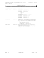
3 FEBRUARY 1993
Issue 1
Original
4 MARCH 1994
Issue 1.1
Addition of Section 1.7
Amendment of Section 2.4
Amendment of Sections:
3.1
3.3.3.6
3.4
Change Section 3.4.3 to 3.4.4
New Section 3.4.3
Amendment of Section 4.6.2
Amendment of Section 5.4
Amendment to Fig 5.2
Amendment to Section 8.2
5 JULY 1995
Issue 2.0
Numerous modifications to the manual.
Updated for V2.00 Compiler software and
V2.00 software in the IO-NET Controller.
Major additions include :
- additions to section 3.3.3.6
- new section 3.3.3.9
- additions to section 3.4
5 FEB 1996
Issue 2.01
New software versions for controller &
compiler released (V2.01).
Pages 1-2,1-3,1-9,1-10,3-11,3-18,4-5,56,5-7,5-8 and 7-2 amended.
Page vi
5 Feb 1996
Issue 2.01
Document: LT0115 IO-NET Programmable Controller User’s Manual
System Description
Chapter 1
SYSTEM DESCRIPTION
&&&&&&&&&&&&&&&&&&&&&&&&&&&&&&&&&&&&&&&&&&&&&&&&&&&&&&&&&&&&&&&&&&&&&&&&
1.1
1.1.1
1.1.2
GENERAL . . . . . . . . . . . . . . . . . . .
Non-Programmed Mode . . . . . . . . . . . . .
Programmed Mode . . . . . . . . . . . . . . .
1-2
1-2
1-3
1.2
F3200/F4000 REMOTE MIMIC PANELS . . . . . . .
1-4
1.3
POINT TO POINT TELEMETRY NON-PROGRAMMED MODE
1-5
1.4
STANDALONE PROGRAMMABLE CONTROLLER
. . . . .
1-6
1.5
AS1668 AIR HANDLING CONTROL FUNCTIONS . . . .
1-7
1.6
INSTALLATION OF COMPILER UTILITY
. . . . . .
1-8
1.7
SOFTWARE VERSION RELEASES . . . . . . . . . .
1-9
))))))))))))))))))))))))))))))))))))))))))))))))))))))))))))))))))))))))
Issue 2.01
5 Feb 1996
Page 1-1
IO-NET Programmable Controller User’s Manual Document: LT0115
System Description
+))))))))))))))))))))))))))))))))))))))))))))))))))))))))))))))))))))))(
* 1.1
GENERAL
$
.(((((((((((((((((((((((((((((((((((((((((((((((((((((((((((((((((((((($
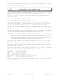
The IO-NET Programmable Controller may operate as a stand-alone unit or
may be linked in a network to other IO-NET Controllers to provide
similar functions to a traditional programmable logic controller.
It can also receive zone data from multiple F4000/F3200 Fire Panels and
provide versatile AS1668 air-handling control functions or remote zone
mimic indicators.
Multiple IO-NET units may be connected together (multidrop 2 or 3 wire)
to provide low cost point-to-point telemetry between multiple locations.
Up to 128 Controllers may be connected to the same network although
physical constraints may limit a system to less than this.
Each IO-NET Controller comprises an IO-NET control card with up to 32
discrete inputs and 32 outputs. Available plug-on I/O termination
boards are as follows:
32
16
32
16
16
input card
input card
digital output (transistor switch)
digital output (transistor switch)
relay output (single pole c/o)
A controller may operate in either programmed or non-programmed mode
according to the setting of a dipswitch on the controller.
In both programmed and non-programmed mode the controller transmits the
states of its 32 inputs on the network (if connected) for use by other
controllers and receives the states of all the inputs on all other
controllers on the network. The zone data received from an F4000/F3200
RZDU data connection may be transmitted onto the network by an IO-NET
controller for other controllers to use without the need to wire the
RZDU data line to all controllers.
NOTE :- there are several versions of IO-NET controller software in
current use and these may be freely mixed on the same network, although
the later versions of software have extra features that earlier versions
do not have. Refer to section 1.7 for software version information.
Page 1-2
5 Feb 1996
Issue 2.01
Document: LT0115 IO-NET Programmable Controller User’s Manual
System Description
1.1.1
NON-PROGRAMMED MODE
4444444444444444444
In non-programmed mode each of the 32 outputs on the controller will
mimic the state of 32 inputs on a different controller - its "pair".
The controller does not have to be programmed with a specific control
program. Non-programmed mode is described in more detail in Chapter 6.
The controller cannot transmit or receive zone data in non programmed
mode.
1.1.2
PROGRAMMED MODE
444444444444444
In programmed mode a specific control program is field programmed into
the controller and the state of the outputs on the controller is
determined by logic expressions defined in the control program. The
control program also includes the definition of network parameters which
allow setting of values such as RTS (Request to Send) delays, etc. The
control program also specifies whether the controller has an RZDU data
input connected and whether it is to transmit that data onto the IO-NET
network or not.
In programmed mode the state of each output is set according to a logic
expression which may include the state of:
1.
2.
3.
4.
5.
6.
7.
8.
one of its own inputs
an input on any other controller on the network
one of its own outputs
any zone on one or more F4000/F3200 fire panels connected to the
network.
one of its own logic variables
some system conditions such as network fault.
the state of a timer
the "scan status" of any IO-NET controller or F4000/F3200 fire
panel.
In programmed mode a control program is generated from a user source
file and is programmed into the controller EPROM. A controller EPROM
can be re-programmed a limited number of times, typically 8 to 12,
depending on the size of the control program.
Examples of possible applications are described in the following
sections.
Issue 2.01
5 Feb 1996
Page 1-3
IO-NET Programmable Controller User’s Manual Document: LT0115
System Description
+))))))))))))))))))))))))))))))))))))))))))))))))))))))))))))))))))))))(
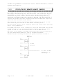
* 1.2
F3200/F4000 REMOTE MIMIC PANELS
$
.(((((((((((((((((((((((((((((((((((((((((((((((((((((((((((((((((((((($
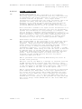
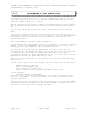
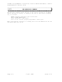
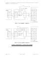
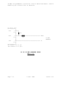
An IO-NET controller may receive F4000 or F3200 zone data from one RZDU
data input wired directly into the controller. The controller may be
programmed to transmit this zone data onto the network so that other
controllers may also receive the zone data without being directly
connected to an RZDU data line, although the same RZDU data line may be
wired into multiple IO-NET controllers if desired. A controller may
receive and access zone data received from both an RZDU data input and
from zone data received on the network.
The controller can be programmed to display the state of one or more
zones which may be from one or more F4000 or F3200 panels.
A local buzzer output can be turned on when a new alarm occurs and reset
with a local pushbutton.
An IO-NET Controller can be connected to both the F4000 RZDU bus and the
IO-NET network, ie. it can simultaneously receive data from an F4000
system as well as send and receive data on the IO-NET network.
The limit on the number of IO-NET controllers which can be connected to
the same F4000/F3200 RZDU data line is hardware dependent.
Further details on using zone data are given in section 3.4 and 8.
32
I/Ps
O/Ps
32
I/Ps
O/Ps
32
I/Ps
O/Ps
Page 1-4
F4000
RZDU BUS
*
*
->+))), *
*IO /))*NET/)),
<-.)))- *
* IO-NET
* network
*
->+))), *
*IO /))1
*NET* *
<-.)))- *
/))))))))))))))))
*
*
*
->+))), *
*IO /))*NET*
<-.)))-
5 Feb 1996
To other IO-NET
controllers if
necessary.
Issue 2.01
Document: LT0115 IO-NET Programmable Controller User’s Manual
System Description
+))))))))))))))))))))))))))))))))))))))))))))))))))))))))))))))))))))))(
* 1.3
POINT-TO-POINT TELEMETRY
$
*
NON-PROGRAMMED MODE
$
.(((((((((((((((((((((((((((((((((((((((((((((((((((((((((((((((((((((($
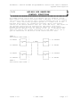
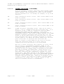
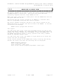
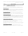
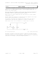
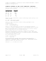
An IO-NET Controller may operate in non-programmed mode where the
outputs on one controller mimic the inputs of another controller.
+))))))),
+))))))),
32I->*
*
*
*-> 32O
*IO-NET /))))))))))))))/))))))))))))))1IO-NET *
32O<-* # 0 *
2 WIRE
* # 1 *<- 32I
.))))))).)))))))Further details on non-programmed mode are given in Section 6.
Issue 2.01
5 Feb 1996
Page 1-5
IO-NET Programmable Controller User’s Manual Document: LT0115
System Description
+))))))))))))))))))))))))))))))))))))))))))))))))))))))))))))))))))))))(
* 1.4
STAND-ALONE PROGRAMMABLE
$
*
CONTROLLER
$
.(((((((((((((((((((((((((((((((((((((((((((((((((((((((((((((((((((((($
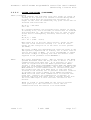
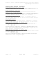
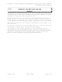
An IO-NET Controller may operate as a stand-alone unit without
connection to a network.
The outputs can be programmed to operate based on a logic function
involving the inputs and other output states.
+)))))),
+)))))))))))))))))),
+)))))),
UP TO 32*
/))))1
/))))1
*UP TO 32
INPUTS*INPUT /))))1
/))))1OUTPUT*OPEN
*TERM *
*IO-NET CONTROLLER *
*TERM *COLLECTOR
*BD
/))))1
/))))1BD
*OR
*
/))))1
/))))1
*RELAY
.)))))).)))))))))))))))))).))))))-OUTPUTS
Page 1-6
5 Feb 1996
Issue 2.01
Document: LT0115 IO-NET Programmable Controller User’s Manual
System Description
+))))))))))))))))))))))))))))))))))))))))))))))))))))))))))))))))))))))(
* 1.5
AS1668 AIR HANDLING
$
*
CONTROL FUNCTIONS
$
.(((((((((((((((((((((((((((((((((((((((((((((((((((((((((((((((((((((($
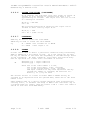
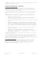
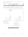
An IO-NET network can be used to do AS1668 type air handling control
where remote controllers scattered round a building or site are used to
turn electric fans on and off and to monitor whether the fan is running
or not. Other controllers grouped together at a common site in the
building have inputs (eg. pushbutton switches) which allow manual
control of the remote electric fans (ie. start and stop). The inputs on
the grouped controllers are monitored by the remote controllers.
Grouped controllers monitor the state of inputs on remote controllers
which indicate whether a fan is running or not (ie. a checkback) and
these are used by the grouped controllers to turn LED’s on or off to
give an indication of the state of the remote electric fans.
PANEL 0
F3200/F4000 RZDU LINK....
+)))))),
:
+)))))),
32 INPUTS ->*
*
:
*
*->
*IO-NET*...:
2 WIRE
*IO-NET*
* #1
/))))))0)))/)))0)))))1 #3
*
*
*
*
*
*
*
32 OUTPUTS <-*
*
*
*
*
*<.))))))*
*
.))))))*
*
*
*
*
*
+)))))),
*
*
+)))))),
32 INPUTS ->*
*
*
*
*
*->
*IO-NET*
*
*
*IO-NET*
* #2
/)))))).)))))1 #4
*
*
*....
*
*
32 OUTPUTS <-*
*
:
*
*<.)))))):
.))))))PANEL 1
:
F3200/F4000 RZDU LINK...:
Issue 2.01
5 Feb 1996
32 OUTPUTS
32 INPUTS
32 OUTPUTS
32 INPUTS
Page 1-7
IO-NET Programmable Controller User’s Manual Document: LT0115
System Description
+))))))))))))))))))))))))))))))))))))))))))))))))))))))))))))))))))))))(
* 1.6
INSTALLATION OF COMPILER
$
*
UTILITY
$
.(((((((((((((((((((((((((((((((((((((((((((((((((((((((((((((((((((((($
The IO-NET programming facility consists of a number of files on an
MS_DOS floppy disk and a programming module. The module is connected to
the PC serial port and a PSU for operation. The files on the floppy
disk should be installed on the PC as follows.
The files required to run the compiler/programmer on a PC are:
IONETCPL.EXE (for use with V2.00 or later controllers)
COMPIOR.EXE (for use with V1.00,1.01,1.02 controllers)
DUMPMEM.BIN
PROGSBC8.BIN
PROGSBC9.BIN
and these should all reside in the same directory and for convenience
the directory should be included in the PATH search setting.
These files do not have to reside in the user work directory. "User
work directory" refers to the directory containing the source control
programs written by the user.
There are also some text files supplied which contain the assignment of
default parameter values which need to be included in every user source
file.
These files are:
NETPRMV3.120
NETPRMV3.240
NETPRMV3.480
NETPRMV3.960
NETPRMV3.12M
(for version 2.00 or later controllers /
version 2.00 compiler
)
NETPRMV2.240
NETPRMV2.480
NETPRMV2.960
NETPRMV2.12M
NETPRMV2.120
(for version 1.02,1.01,1.00 controllers /
version 1.02 compiler
)
and should be copied to the user work directory.
Page 1-8
5 Feb 1996
Issue 2.01
Document: LT0115 IO-NET Programmable Controller User’s Manual
System Description
+))))))))))))))))))))))))))))))))))))))))))))))))))))))))))))))))))))))(
* 1.7
SOFTWARE VERSION RELEASES
$
.(((((((((((((((((((((((((((((((((((((((((((((((((((((((((((((((((((((($
IO-NET Controller V1.00
First release of controller software February 1993.
IO-NET Controller V1.01
Second release of controller software March 1994.
This version includes the capability of operating with either
"Non-LCD RZDU protocol" or "LCD RZDU protocol". Refer to Sections
3.4.3 and 8.2.
For a controller which does not access any zone data (ie. does not
receive RZDU data from an F4000/F3200 Fire Panel) or is operating
in non-programmed mode, there is no difference between Controller
V1.00 software and Controller V1.01 software.
IO-NET Controller V1.02
Third release of controller software November 1994.
This version is operationally identical to V1.01 controller and
was created to match a small change in a new release of the
MOTOROLA MC68HC705C8 processor.
IO-NET Controller V2.00
Fourth release of controller software July 1995.
This version includes some new features including
- use of timers in the control program
- transmission of zone data over the network to reduce the
amount of wiring required
- accessing zone data from multiple F4000/F3200 fire panels
- detection of scan fail on individual IO-NET controllers
and F4000/F3200 panel links in addition to the INF/ZNF
facility.
IO-NET Controller V2.01
Fifth release of controller software FEB 1996. Corrects problem
with transient invalid input states in low current mode.
IO-NET Compiler V1.00 (COMPIOR.EXE program)
First release February 1993.
This version may be used with either V1.00 Controller software or
V1.01/1.02 Controller software but does not provide the RZDP
parameter which may be needed by V1.01 Controller software. Ie.
it cannot be used to compile programs for Controllers requiring
the LCD RZDU protocol.
Issue 2.01
5 Feb 1996
Page 1-9
IO-NET Programmable Controller User’s Manual Document: LT0115
System Description
1.7
SOFTWARE VERSION RELEASES (CONTINUED)
IO-NET Compiler V1.01 (COMPIOR.EXE)
Second release March 1994.
This version allows the programming of the RZDU protocol type with
the RZDP parameter. Refer to Sections 3.4.3 and 8.2.
This version may be used with either V1.00 Controller software or
V1.01/1.02 Controller software. A V1.00 Controller will ignore
the RZDP parameter if it is included and can operate only with
"Non-LCD RZDU protocol".
IO-NET Compiler V1.02 (COMPIOR.EXE)
Third release JULY 1995.
This version corrects a software bug in V1.01,V1.00 COMPIOR.EXE
compiler software.
This version is for use with V1.00,1.01,1.02 controllers and
cannot be used with V2.00 or later controllers.
If an attempt is made to use it to program V2.00 or later
controller then an error message will be given.
IO-NET Compiler V2.00 (IONETCPL.EXE)
NOTE NEW FILE NAME IONETCPL.EXE
Third release JULY 1995.
This version includes some new features, including
- use of timers in the control program
- transmission of zone data over the network to reduce the
amount of wiring required
- accessing zone data from multiple F4000/F3200 fire panels
- detection of scan fail on individual IO-NET controllers
and F4000/F3200 panel links in addition to the INF/ZNF
facility.
This version can be used with version 2.00 or later controllers
only. If an attempt is made to use it to program V1.02 or earlier
controller then an error message will be given.
IO-NET Compiler V2.01 (IONETCPL.EXE)
Fourth release FEB 1996.
Allow both [] and () in timer equation T[5,10]=... .
IO-NET network monitoring diagnostic program V2.00.
First release JULY 1995. IONETM1.EXE (COM1). IONETM2.EXE (COM2).
This program runs on a PC and can receive (but not transmit)
messages from the network and display them, to allow the operation
of the network to be observed.
Page 1-10
5 Feb 1996
Issue 2.01
Document: LT0115 IO-NET Programmable Controller User’s Manual
Specifications
Chapter 2
SPECIFICATIONS
&&&&&&&&&&&&&&&&&&&&&&&&&&&&&&&&&&&&&&&&&&&&&&&&&&&&&&&&&&&&&&&&&&&&&&&&
2.1
GENERAL . . . . . . . . . . . . . . . . . . .
2-2
2.2
INPUT SPECIFICATIONS
. . . . . . . . . . . .
2-3
2.3
OUTPUT SPECIFICATIONS . . . . . . . . . . . .
2-4
2.4
ORDERING CODES
2-5
. . . . . . . . . . . . . . .
))))))))))))))))))))))))))))))))))))))))))))))))))))))))))))))))))))))))
Issue 2.01
5 Feb 1996
Page 2-1
IO-NET Programmable Controller User’s Manual Document: LT0115
Specifications
+))))))))))))))))))))))))))))))))))))))))))))))))))))))))))))))))))))))(
* 2.1
GENERAL
$
.(((((((((((((((((((((((((((((((((((((((((((((((((((((((((((((((((((((($
Dimensions:
Main PCB
16 I/O PCBs
32 I/O & 16 Relay PCBs
Format:
Supplied as circuit boards for incorporation in other
equipment enclosures.
Power Supply:
24Vdc (17.5-28V)
Inputs:
Common ground. Clean contacts or end-of-line
monitored. Limited analog values available for
special applications software.
Outputs:
Open collector closure to 0V.
Relay Outputs:
Single pole changeover. Contacts rated 30V, 2 Amps
(resistive), 1A (inductive DC); 1A (AC inductive and
resistive).
Network Length:
At a baud rate of 2400 and with 1mm diameter wire the
total length should not exceed 3 kilometres. At 9600
baud the maximum length is 1 kilometre with 1mm
diameter wire.
Network Address:
31 (32 IO-NET Controllers) in non-programmed mode.
127 (128 IO-NET Controllers) in programmed mode.
Network Baud
Rates:
1200, 2400, 4800 or 9600
RZDU Data Line
Length:
System Response
Time:
Page 2-2
165mmW x 270mmH
93mmW x 135mmH
93mmW x 270mmH
Maximum 30V, 200mA.
With 1mm wire the maximum length is 1km.
Section 8.4 gives same information on the response
times and delays that occur in an IO-NET system.
5 Feb 1996
Issue 2.01
Document: LT0115 IO-NET Programmable Controller User’s Manual
Specifications
+))))))))))))))))))))))))))))))))))))))))))))))))))))))))))))))))))))))(
* 2.2
INPUT SPECIFICATIONS
$
.(((((((((((((((((((((((((((((((((((((((((((((((((((((((((((((((((((((($
IO-NET Controller inputs operate with either low current pullup or high
current pullup according to the setting of dipswitch I0 on the IO-NET
Controller board. With I0 off all inputs are high current pullup and
with I0 on all inputs are low current pullup.
End of Line (normalising) Resistor
3K3 300mW for high current pullup
27K 300mW for low current pullup
On an input termination board each input has a 10V zener diode and 100N
capacitor for transient suppression.
The following table shows the voltage and resistance thresholds and
ranges for the four input conditions - open circuit, normal, alarm and
short circuit.
Thresholds & Ranges for High Current/Low Current Pullup
State
Voltage
(Nominal)
Resistance
(Ohms)
Thres.
High Current Pullup
Nom.
Range
Mid
5V
O/C
Open
Circuit
Low Current Pullup
Nom.
Range
O/C
>13K
>180K
4.16V
Normal
3.33V
3K3
2K1-5K5
27K
1.66V
830E
475E-1K25
(1)
6K8
17K-48K
2.50V
Alarm
3K85-11K
(2)
0.83V
Short
Circuit
<200E
0V
S/C
Line Capacitance:
Hi Current Pull Up Lo Current Pull Up -
<1K75
S/C
500nF maximum
300nF maximum
Notes
1.
Nominal 830E achieved by 820E or 3K3 parallel with 1K1 (or 1K2).
2.
Nominal 6K8 achieved by 6K8 or 27K parallel with 9K1 (or 10K).
3.
The resistance ranges show the values of resistance for which the
appropriate state is guaranteed.
Issue 2.01
5 Feb 1996
Page 2-3
IO-NET Programmable Controller User’s Manual Document: LT0115
Specifications
+))))))))))))))))))))))))))))))))))))))))))))))))))))))))))))))))))))))(
* 2.3
OUTPUT SPECIFICATIONS
$
.(((((((((((((((((((((((((((((((((((((((((((((((((((((((((((((((((((((($
24V OUTPUT
VOLTAGE
-
Greater than Supply Voltage (at IO-NET) minus
2.5V.
CURRENT
-
Limited to 650mA typical (500mA min, 800mA max)
ACCESS
-
3 Way terminal block on Termination or Relay Bd.
Common terminals on Output Termination Bd.
OPEN COLLECTOR OUTPUTS
NUMBER
-
32 max
"OFF" VOLTAGE
-
28.5V max
"ON" VOLTAGE
-
1V max at 30mA, 1.1V max at 100mA.
"ON" CURRENT
-
100mA max per output.
TERMINATION
OPTIONS
-
16 way Output Termination
Screw terminals, 1.5sq mm
32 way Output Termination
Screw terminals, 1.5sq mm
16 Way Relay Board.
Screw terminals, 1.5sq mm
-
Board.
max cable size.
Board.
max cable size.
max cable size.
RELAY OUTPUTS
16 WAY RELAY BD
TYPE
-
Single Pole Changeover.
RATING
-
2A @ 30Vdc Resistive, 1A @ 30Vdc Inductive.
1A @ 30Vac Resistive, 1A @ 30Vac Inductive.
QUIESCENT CURRENT -
Nil (ie. for relays all off).
OPERATED CURRENT
11.5mA @ 24Vdc per operated relay.
Page 2-4
-
5 Feb 1996
Issue 2.01
Document: LT0115 IO-NET Programmable Controller User’s Manual
Specifications
+))))))))))))))))))))))))))))))))))))))))))))))))))))))))))))))))))))))(
* 2.4
ORDERING CODES
$
.(((((((((((((((((((((((((((((((((((((((((((((((((((((((((((((((((((((($
The following gives the part number of PCBs associated with the IO-NET
system, together with a brief description of their use.
PA0498 PCB ASSEMBLY,1901-117,IO-NET CONTROLLER
This is the IO-NET Controller PCB.
Field connection of inputs\output is provided by screw terminals on
separate termination boards. These connect to the IO-NET Controller by
26 way FRCs (Flat Ribbon Cables) which have to be ordered separately.
PA0474 PCB ASSEMBLY,1901-73-1,F4000 IOR 32 WAY INPUT TERM BD
PA0479 PCB ASSEMBLY,1901-73-1,F4000 IOR 16 WAY INPUT TERM BD
These allow termination of up to 1.5mm² field wiring and carry the
transient voltage protection components. One FRC is required for each
16 inputs. A PA0479 is half of a PA0474.
PA0475 PCB ASSEMBLY,1901-73-2,F4000 IOR 32 WAY O/P TERM BD
PA0480 PCB ASSEMBLY,1901-73-2,F4000 IOR 16 WAY O/P TERM BD
These allow termination of up to 1.5mm² field wiring to the open
collector outputs. Each output has a protection diode to the positive
supply.
There are single +V, 0V and Earth terminals for each 16 outputs.
One 16 way FRC is required for each 16 outputs. A PA0480 is half of a
PA0475.
PA0470 PCB ASSEMBLY,1901-64,F4000 16 WAY RELAY BOARD
Provides 16 sets of changeover clean contacts and includes voltage
transient protection and suppression components on the coil. There are
single +V, 0V and Earth terminals for each relay board. One 1.4m 26 way
FRC is supplied with each relay board.
LM0044
LM0045
LM0046
LM0049
LM0056
LOOM,1901-81-1,26
LOOM,1901-81-2,26
LOOM,1901-81-3,26
LOOM,1901-81-4,26
LOOM,1901-81-5,26
WAY
WAY
WAY
WAY
WAY
FRC,2M
FRC,5M
FRC,0.5M
FRC,250MM
FRC,1.2M
These 26 way FRCs provide the inter-connection between the IO-NET
Controller and the input/output termination and relay boards.
PA0481 PCB ASSEMBLY,1901-100,F4000 RZDU/RS232 I/F BOARD
This converts the F4000 RZDU Comms line into a voltage compatible with
the IO-NET Controller. Issue A can drive up to 5 IO-NET Controllers on
up to 200m of cable. Issue B versions can drive up to 32 Controllers on
up to 2km of cable.
Issue 2.01
5 Feb 1996
Page 2-5
IO-NET Programmable Controller User’s Manual Document: LT0115
Specifications
ORDERING CODES (CONTINUED)
PA0483 PCB ASSEMBLY,1901-103,F4000 IOR UNPROTECTED TERM BOARD
This provides screw terminals for the 16 inputs or outputs on 1 26 way
FRC from the IO-NET Controller. It should only be used for protected
wiring inside a cabinet as it provides no transient protection for the
inputs or outputs. Screw terminals for +V and 0V are also provided.
PA0700 PCB ASSEMBLY,1901-120,IO-NET PROGRAMMING MODULE
Programming module for "burning" of programmed mode EPROMs. Includes
cable to connect to PC and programming software (SF0088). Requires 24V
(19.2-28.3V) DC power supply for operation.
PA0464 PCB ASSEMBLY,1830-40-1,1200 BAUD MODEM CMOS/4 WIRE
This modem is suitable for use with IO-NET Controller. Refer to the
Technical Manual for this product for full details. Special wiring of
the modem to the IO-NET Controller is required.
SF0087 SOFTWARE,IO-NET CONTROLLER,V2.00,OTP
"Blank" OTP microprocessor for IO-NET Controller. Already programmed
for non-programmed mode operation and for programmed mode the user
program space is all blank.
SF0088 SOFTWARE,IO-NET COMPILER,V2.00,DISK C/W MANUAL
PC Compiler software and user manual. The disk includes two versions of
software. Version 2.00 is for use with V2.00 or later Controller.
Version 1.02 compiler is also supplied and is for use with Version 1.02,
1.01 or 1.00 Controllers.
LT0115 LITERATURE,1901-121,IO-NET USER MANUAL
This document.
Page 2-6
Supplied with SF0088 and PA0700.
5 Feb 1996
Issue 2.01
Document: LT0115 IO-NET Programmable Controller User’s Manual
Generating a Source File
Chapter 3
GENERATING A SOURCE FILE
&&&&&&&&&&&&&&&&&&&&&&&&&&&&&&&&&&&&&&&&&&&&&&&&&&&&&&&&&&&&&&&&&&&&&&&&
3.1
INTRODUCTION
. . . . . . . . . . . . . . . .
3-2
3.2
ADDING NETWORK PARAMETERS TO THE USER
SOURCE FILE . . . . . . . . . . . . . . . . .
3-3
3.3
3.3.1
3.3.2
3.3.3
3.3.3.1
3.3.3.2
3.3.3.3
3.3.3.4
3.3.3.5
3.3.3.6
3.3.3.7
3.3.3.8
OUTPUT LOGIC EXPRESSIONS . . . .
General Format . . . . . . . . .
Order of Evaluation of Operands .
Operand Types . . . . . . . . . .
IO-NET Controller Circuit Inputs
Controller Outputs . . . . . . .
F4000/F3200 Zone Data . . . . . .
Variables . . . . . . . . . . . .
The New Alarm (NA) Function . . .
System Conditions . . . . . . . .
Constants . . . . . . . . . . . .
Timers . . . . . . . . . . . . .
3.4
3.4.1
3.4.2
3.4.3
3.4.4
.
.
.
.
.
.
.
.
.
.
.
.
.
.
.
.
.
.
.
.
.
.
.
.
.
.
.
.
.
.
.
.
.
.
.
.
.
.
.
.
.
.
.
.
.
.
.
.
.
.
.
.
.
.
.
.
.
.
.
.
3-4
3-4
3-8
3-9
3-10
3-10
3-11
3-12
3-13
3-15
3-18
3-18
. .
. .
. .
. .
The
. .
. .
. .
. .
.
.
.
.
3-27
3-27
3-28
3-29
3.4.5
3.4.6
3.4.7
ASSIGNING VALUES TO NETWORK PARAMETERS
Assigning Target Station Address . . .
Assigning Maximum Station Number . . .
Enabling Local RZDU Data Input . . . .
Enabling Transmission of Zone Data Onto
Network . . . . . . . . . . . . . . . .
Assigning RZDU Protocol Type . . . . .
Using the MRAM Parameter . . . . . . .
Other Network Parameters . . . . . . .
.
.
.
.
3-30
3-30
3-31
3-32
3.5
3.5.1
3.5.2
3.5.3
EXAMPLE PROGRAMS . . . . . . . . . .
Duplicating Non-Programmed Mode . . .
Passing Data on to the IO-NET Network
Accessing Zones . . . . . . . . . . .
.
.
.
.
.
.
.
.
3-33
3-33
3-33
3-34
.
.
.
.
.
.
.
.
.
.
.
.
.
.
.
.
.
.
.
.
))))))))))))))))))))))))))))))))))))))))))))))))))))))))))))))))))))))))
Issue 2.01
5 Feb 1996
Page 3-1
IO-NET Programmable Controller User’s Manual Document: LT0115
Generating a Source File
+))))))))))))))))))))))))))))))))))))))))))))))))))))))))))))))))))))))(
* 3.1
INTRODUCTION
$
.(((((((((((((((((((((((((((((((((((((((((((((((((((((((((((((((((((((($
A source file consists of a text file containing logic expressions to
control the state of the outputs on the controller.
It also includes the setting of some "network parameters" such as RTS
delay, etc, and configuration parameters such as RZDU, RZDP, TXZD.
Every source file must include the assignment of values to all of the
network parameters. Assignment of parameters RZDU, RZDP and TXZD is
optional. Parameters RZDU,RZDP,TXZD are optional. An error will occur
if any of the network parameter assignments are missing.All network and
configuration parameters must appear before any logic expression
statements.
Any valid file name may be used for the name of the source file but it
is recommended that some consistent naming of files be used.
For example, PROJNAME.S0 where PROJNAME is the name of the project or
building etc, and the extension is the IO-NET controller number.
Also keep a record of the physical location of the IO-NET Controller
associated with each source file. This could be included as a comment
in the source file.
After making any changes to a user source file the file should be backed
up to floppy disk.
A base file is supplied called NETPRMV3.240 which supplies default
assignments for all of the required network parameters for a network
operating at 2400 baud.
Alternative files are supplied for 9600, 4800 and 1200 modem baud rate
systems.
File
File
File
File
NETPRMV3.960
NETPRMV3.480
NETPRMV3.120
NETPRMV3.12M
is
is
is
is
for
for
for
for
9600
4800
1200
1200
baud
baud
baud (without modems)
baud with modems
Version 1.01/1.02 of the programmer software COMPIOR.EXE file uses an
earlier set of parameter files which are NETPRMV2.240, NETPRMV2.480,
NETPRMV2.960 and NETPRMV2.12M.
If accessing zone information from an RZDU link the parameter RZDP
should always be included to specify the RZDU protocol type. The RZDU
parameter is used to specify the panel number associated with the zone
data received from the RZDU data connection.
Page 3-2
5 Feb 1996
Issue 2.01
Document: LT0115 IO-NET Programmable Controller User’s Manual
Generating a Source File
+))))))))))))))))))))))))))))))))))))))))))))))))))))))))))))))))))))))(
* 3.2
ADDING NETWORK PARAMETERS TO THE
$
*
USER SOURCE FILE
$
.(((((((((((((((((((((((((((((((((((((((((((((((((((((((((((((((((((((($
The first step in creating a source file is to copy the appropriate
network parameter file to a new source file.
eg. COPY NETPRMV3.240 USERFIL1.TXT
will create the text file USERFIL1.TXT.
DO NOT do this copy command if USERFIL1.TXT already exists as it will
destroy the existing contents of USERFIL1.TXT. (In this case use an
editor (eg. EDIT) to edit the existing file USERFIL1.TXT and insert the
contents of the NETPRMV3 file).
Alternatively, use the DOS COPY command to append the NETPRMV3 file to
the end of USERFIL1.TXT with the command:
COPY USERFIL1.TXT + NETPRMV3.240
You will then need to use an editor to move the parameters from the end
of the file to the start, since all parameters MUST appear before any
logic expressions.
WARNING
Be careful when using the copy command to append two files
together. The example given of COPY USERFIL1.TXT +
NETPRMV3.240 will work correctly and append the file
NETPRMV3.240 to USERFIL1.TXT. However, if the command is
entered incorrectly it could result in one of the files
being destroyed.
If unsure, make backup copies of the files involved first.
Every source file must include the assignment of network parameters,
even if the target controller is not going to be connected to an IO-NET
network.
The values of network parameters may be modified if desired.
of network parameters is described in Section 3.4.
The usage
A source file may consist of network parameters only - it does not have
to include any output logic expressions. If there are no output logic
expressions then the controller will never control any outputs but will
still transmit the state of its inputs onto the network and also
transmit zone data onto the network if programmed to (with TXZD).
Issue 2.01
5 Feb 1996
Page 3-3
IO-NET Programmable Controller User’s Manual Document: LT0115
Generating a Source File
+))))))))))))))))))))))))))))))))))))))))))))))))))))))))))))))))))))))(
* 3.3
OUTPUT LOGIC EXPRESSIONS
$
.(((((((((((((((((((((((((((((((((((((((((((((((((((((((((((((((((((((($
3.3.1
GENERAL FORMAT
44444444444444
A source file may contain any number of output logic expressions
(limited only by the available space in the target EPROM) which assign
the value of an expression to a local output or internal variable or
timer.
eg.
O4 = I7/9O OR I15/1A AND V3
; to control output 4
and may also assign values to logic variables
eg.
V5 = V4 + I3/26A
and to timers
eg.
T1[15,25] = I1/4S
At run time the target controller will evaluate all of the logic
expressions sequentially in exactly the order they appear in the source
file.
When the controller gets to the end of the logic expressions it returns
to the start and cycles through forever.
Expressions which assign values to outputs do NOT have to appear in
numerical order of the output number. They may be in any order however, the order that the expressions appear in the source file does
NOT determine the order in which the PHYSICAL output changes. The
physical state of the outputs is only updated at the completion of each
pass through the entire list of logic expressions (and also at intervals
of 100 milliseconds) so that the actual state of the physical output may
not necessarily follow the logical state of the output generated by the
logic expressions if the logical state changes quickly.
There does not have to be a logic expression for every output.
The same output should be controlled by ONLY ONE EXPRESSION and the
compiler will display a warning message if more than one expression is
given for the same output.
eg.
O5 = V1 OR V2
O6 = I1/1A
O5 = O6 OR I29/3S
is controlling output 5 with two different expressions and the actual
state which appears at the physical output will be intermittent.
Page 3-4
5 Feb 1996
Issue 2.01
Document: LT0115 IO-NET Programmable Controller User’s Manual
Generating a Source File
GENERAL FORMAT (CONTINUED)
Similarly, the program should not contain more
defining the input condition and start/stretch
The compiler will display a warning if this is
timer may be accessed as many times as desired
the "right hand side" of a logic expression.
than one expression
delays of the same timer.
done. The state of a
in multiple equations on
Expressions which assign values to variables may be in any order with
more than one expression for the same variable being allowed if desired.
The variable will then keep that value until the next occurrence of an
expression which assigns a value to that variable. It is recommended
that the same variable is not used for two different purposes except
perhaps by an experienced user or if the compiler produces a "RAM limit
exceeded" error.
Comments may be included anywhere in the source file. Any text on the
same line following a semicolon ; is treated as a comment with the
exception of the semicolon used in the NA function.
Be careful not to unintentionally convert a real logic expression into a
comment by accidentally placing a semicolon at the start of or part way
through, a logic expression.
Blank lines may appear anywhere in the source file.
Each logic expression must fit entirely on a single line but long lines
are allowed- up to 299 characters (if your editor allows this many).
Variables can be used to simplify complex or long expressions.
Following the last logic expression in the file, the keyword END must
appear on a new line to terminate the list of expressions. Any lines
following the END statement may contain comments only.
Upper or lower case characters are allowed everywhere and are treated
identically.
A logic expression does not have to start in column one, it may start in
any column ie. a logic expression may be preceded by any number of
blanks on that line.
In general, individual operands such as I15/3A should not contain any
embedded blank characters (in some cases this is not strictly enforced
and embedded blanks are allowed) but spaces may be used freely between
operands and operators.
It is not essential to have any spaces between operands and operators
but they should be included for clarity.
Issue 2.01
5 Feb 1996
Page 3-5
IO-NET Programmable Controller User’s Manual Document: LT0115
Generating a Source File
GENERAL FORMAT (CONTINUED)
Each logic expression is of the form :
Ox = Operand {Binary operator Operand} ...
to assign the state of output x (x = 1 to 32)
or
Vx = Operand {Binary operator Operand} ...
to assign a value to logic variable x (x = 1 to 256).
or
Tx[mmm,nnn] = Operand {Binary operator Operand} ...
to define the input condition and timer delays (start, stretch) for
timer x (x = 1 to 128). The start delay (mmm) and stretch delay (nnn)
are required and may be any value from 0 to 255 seconds.
The curly brackets {} which are not part of the expression indicate that
their contents are optional and may be repeated any number of times.
The right hand side of each expression consists of one or more operands
with each pair of operands separated by a binary operator.
All operands return a logical value of TRUE or FALSE. If the right hand
side of an expression evaluates to TRUE then the specified output on the
left hand side will be turned ON (and FALSE = OFF) or if the left hand
side is a variable, then the variable will be assigned a value of TRUE
or FALSE. The operation of timers is described in section 3.3.3.8.
If the output or variable which appears on the left hand side of the =
also appears as an operand on the right hand side then the value used on
the right hand side is the value of the operand before the new
assignment.
Any operand may be preceded by the unary operator NOT (the symbol ^ may
also be used) which complements the value of the operand.
Each operand may itself consist of an expression enclosed in parentheses
() with a maximum nesting level limited by the amount of stack space
required for evaluation at run time. The nesting level limit is 16
which is more than enough for any foreseeable requirement.
Page 3-6
5 Feb 1996
Issue 2.01
Document: LT0115 IO-NET Programmable Controller User’s Manual
Generating a Source File
GENERAL FORMAT (CONTINUED)
The binary operators which may be used are:
AND - logical AND (alternatively use .)
OR - logical OR (alternatively use +)
XOR - exclusive OR
The one unary operator which may be used is:
NOT - logical complement (alternatively use ^)
The single character "+" (plus) may be used instead of OR, the character
"." (fullstop) may be used instead of AND, and the character "^" may be
used instead of NOT.
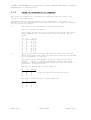
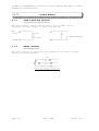
The truth tables for AND,OR,XOR and NOT are (F = FALSE, T = TRUE)
A AND B
A
F
F
T
T
B
F
T
F
T
RESULT
F
F
F
T
A OR B
A
F
F
T
T
B
F
T
F
T
RESULT
F
T
T
T
A XOR B
A
F
F
T
T
B
F
T
F
T
RESULT
F
T
T
F
NOT A
A
F
T
RESULT
T
F
Example
NOT A OR NOT B
A
F
F
T
T
Issue 2.01
B
F
T
F
T
RESULT
T
T
T
F
5 Feb 1996
Page 3-7
IO-NET Programmable Controller User’s Manual Document: LT0115
Generating a Source File
3.3.2
ORDER OF EVALUATION OF OPERANDS
4444444444444444444444444444444
The order of evaluation of operands is important and can affect the
result of the expression.
When more than one operand appears in an expression, the order of
evaluation of the operands is not necessarily left to right but depends
on some rules as follows:
A.
The contents of parentheses are evaluated first.
eg. O3 = V1 AND (V2 OR V3)
will cause "V2 OR V3" to be evaluated first with the result
being "ANDed" with V1 resulting in the following truth
table.
V1
V2
V3 * O3
)))))))))))))3)))
F
F
F * F
F
F
T * F
F
T
F * F
F
T
T * F
T
F
F * F
T
F
T * T
T
T
F * T
T
T
T * T
B.
Each of the operators AND, OR, XOR and NOT have a priority
which determines the order of evaluation when not overridden
with parentheses as follows:
The NOT operator has highest priority, AND has the next
highest
priority, and OR and XOR have equal and lowest
priority. Where operators have equal priority the order of
evaluation is left to right.
Eg. NOT V1 AND V2 has a truth table of:
V1
F
F
T
T
V2
F
T
F
T
RESULT
F
T
F
F
with the "NOT V1" being done first
but NOT (V1 AND V2) has a truth table of:
V1
F
F
T
T
Page 3-8
V2
F
T
F
T
RESULT
T
T
T
F
5 Feb 1996
Issue 2.01
Document: LT0115 IO-NET Programmable Controller User’s Manual
Generating a Source File
ORDER OF EVALUATION OF OPERANDS (CONTINUED)
Eg. V1 OR V2 AND V3 results in the "V2 AND V3" being
evaluated first because the AND operator has a higher
priority than OR.
Operators of equal priority result in evaluation of operands
from left to right. Eg. V1 OR V2 XOR V3 OR V4 XOR V5 will
result in the operands being evaluated in the order they
appear with V1 first and V5 last.
If unsure, use parentheses. The use of parentheses does not
affect the size of object code generated.
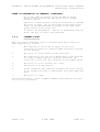
3.3.3
OPERAND TYPES
4444444444444
There are several different types of operands which may be used in a
logic expression as follows:
1.
The condition of one of the 32 inputs on the local
controller or inputs on a remote IO-NET Controller received
via the network.
2.
The state of a local output on the controller.
3.
The condition of any zone on an F4000/F3200 system received
via either an RZDU connection directly wired into the
controller or from zone data received on the IO-NET network.
4.
The state of a local variable V1 to V256.
5.
The "State" of an NA function.
6.
System conditions and constants including the "scan status"
of any IO-NET controller or F4000/F3200 fire panel RZDU data
link.
7.
The state of a timer.
Each operand returns a value of TRUE or FALSE as described in sections
3.3.3.1 to 3.3.3.8 below.
Issue 2.01
5 Feb 1996
Page 3-9
IO-NET Programmable Controller User’s Manual Document: LT0115
Generating a Source File
3.3.3.1
IO-NET CONTROLLER CIRCUIT INPUTS
The four conditions of a circuit input may be accessed as follows:
Ix/yO
Ix/yN
Ix/yA
Ix/yS
(open circuit)
(normal)
(alarm)
(short circuit)
Where x is the address of an IO-NET Controller 0 to 255, y is the number
of a circuit input 1 to 32 and O, N, A, S refer to the four voltage
bands where S is the lowest band (short circuit) and O is the highest
(open circuit). The operand returns true if the circuit input x/y is in
the specified condition O, N, A or S at the time the logic expression is
evaluated.
NOTE - currently the maximum address which can be physically set (with
dipswitches) an a controller is 127 but the compiler allows a controller
number of 0-255 to be used in expressions.
The circuit input x/y can be any input on any IO-NET controller
including the inputs of the controller running this program.
Eg. O1 = I3/15A OR I0/32S results in output 1 being on if either input
15 on controller 3 is in Alarm or if input 32 on controller 0 is in
short circuit.
When the controller is first powered up the initial state of all inputs
will be normal until their true state is received either from the
network for remote controller inputs or from input boards for local
controller inputs. If a local input termination board is not connected
the associated inputs will all be in an open circuit condition.
3.3.3.2
CONTROLLER OUTPUTS
The local outputs can appear as an operand on the right hand side of an
expression as:
OxF or OxN where x is the number of an output 1-32
NOTE
It is not possible to use output states of other
controllers.
OxF returns TRUE if the output is OFF, otherwise FALSE.
OxN returns TRUE if the output is ON, otherwise FALSE.
Eg. O2 = O1F OR 032N; will result in output 2 being ON if output 1 is
off or output 32 is on.
After power-up or re-start of the controller all outputs will initially
be off.
Page 3-10
5 Feb 1996
Issue 2.01
Document: LT0115 IO-NET Programmable Controller User’s Manual
Generating a Source File
3.3.3.3
F4000/F3200 ZONE DATA
The condition of a zone on an F4000/F3200 fire panel may be accessed as
follows:
Zpp:nnnA
Zpp:nnnF
Zpp:nnnI
Zpp:nnnN
returns TRUE
returns TRUE
returns TRUE
returns TRUE
not in fault
if
if
if
if
or
zone in alarm and NOT isolated
zone in fault and NOT isolated
the zone is isolated
the zone is not isolated and
alarm.
where pp is a panel number, 0-63, nnn is a zone number 1-528. Zone data
from multiple fire panels may be accessed but the total number of panels
accessed should be 8 or less.
Each IO-NET controller which has an RZDU data link directly connected is
programmed with a panel number and whether the zone data should be
transmitted over IO-NET or not (TXZD). The zone data which it transmits
onto the IO-NET network will include the panel number for identification
by other controllers. Any controller may access zone data from both its
own directly connected RZDU data link and from zone data which it
receives via the IO-NET network.
eg.
O32 = Z3:1A AND Z4:528N
results in output 32 being on if zone 1 on panel 3 is in
alarm (and not isolated) and zone 528 on panel 4 is normal.
When the zone corresponds to an Ancillary Control Zone on F4000 or a
relay on an F3200 FIP then the conditions A,I,F,N are
Zpp:nnnA
Zpp:nnnF
Zpp:nnnI
Zpp:nnnN
returns TRUE
returns TRUE
returns TRUE
returns TRUE
not in fault
if
if
if
if
or
zone activated and NOT isolated
zone in fault and NOT isolated
the zone is isolated
the zone is not isolated and
activated.
After power-up or restart of the controller the state of all zones will
initially be normal until the current actual state is received. This
could take up to 7 or 8 minutes for a system with 528 zones depending on
which version of software is being used in the F4000 panel. In the
latest version of F4000 panel software the time to refresh the state of
all 528 zones is approximately 70 seconds.
Issue 2.01
5 Feb 1996
Page 3-11
IO-NET Programmable Controller User’s Manual Document: LT0115
Generating a Source File
3.3.3.4
VARIABLES
Variables may be used for storage of logical values.
A variable is accessed with Vnnn
where nnn is a value 1-256.
There are up to 256 variables available, the actual number limited by
available RAM storage in the controller. A variable has a logical value
of either TRUE or FALSE.
eg.
V1
V2
V3
V4
=
=
=
=
Z1A OR Z2F
I0/1A OR I0/2S
V1 OR V2
V1 AND V2
Variables should be used "contiguously" starting with V1, then V2,
V3 .... etc, to minimise RAM usage in the IO-NET Controller.
The compiler will display an error message if the RAM storage limits of
the controller are exceeded.
When the controller is first powered up or restarted, the initial value
of all variables is FALSE.
A variable may be useful for holding the result of an expression which
is common to several different logic expressions. This can result in a
saving of EPROM space.
Variables are also useful in NA functions because an NA function is not
allowed to use an expression in its operand list. This can be overcome
by assigning the expression to a variable first and accessing the
variable in the NA function.
Variables are also useful for other things. For example, the expression
V1 = NOT V1
will toggle the value of V1 each time it is executed and
produce an oscillating value.
The expression
V1 = V1 OR ZNF
will latch the occurrence of a zone network fault.
Page 3-12
5 Feb 1996
Issue 2.01
Document: LT0115 IO-NET Programmable Controller User’s Manual
Generating a Source File
3.3.3.5
THE NEW ALARM (NA) FUNCTION
The NA function may be used as an operand in any logic expression and
has the form:
NA (reset input; operand list)
where operand list consists of a list of fundamental operands separated
by commas and includes:
OnnF
OnnN
Ix/yO
Ix/yN
Ix/yA
Ix/yS
Vnnn
Zpp:nnnA
Zpp:nnnF
Zpp:nnnI
Zpp:nnnN
Tnnn
IRnnn
PRnn
-
local output nn (1-32) off
local output nn (1-32) on
input y (1-32) on controller x (0-127) open circuit
input y on controller x normal
input y on controller x alarm
input y on controller x short circuit
variable nnn (1-256)
zone pp:nnn (1-528) alarm (and not isolated)
zone pp:nnn fault (and not isolated)
zone pp:nnn isolated
zone pp:nnn normal (not A,I or F)
timer nnn (1-128) state
IO-NET controller responding status
Fire Panel responding status
and "reset input" may be any one of the above fundamental operands ie.
it is a single operand such as I5/I2S or V15 or Z1:42A, etc.
The operand list may not include expressions ie.
XOR may not be used in an NA function. If it is
expression in an NA function then the expression
assigned to a variable and the variable included
operators NOT, AND, OR,
desired to use an
should first be
in the operand list.
The NA function returns a value of TRUE or FALSE as follows. Whenever
any operand in the list has a change of state from FALSE to TRUE then
the function returns a value TRUE and continues to return a value TRUE
(forever regardless of any further changes of state in the operand list)
until the specified reset input has a change of state from FALSE to
TRUE. At this point NA returns FALSE and continues to return FALSE
until the next change of state from FALSE to TRUE of any operand in the
list.
Issue 2.01
5 Feb 1996
Page 3-13
IO-NET Programmable Controller User’s Manual Document: LT0115
Generating a Source File
3.3.3.5
THE NEW ALARM (NA) FUNCTION (CONTINUED)
The same operand may appear any number of times in the list.
eg.
NA(I5/12S; 03N, I7/25A, Z0:124A, V15)
This function is set to TRUE whenever one of the operands in the list
becomes TRUE. Eg. if local output 3 changes state from off to on or if
input 25 on controller 7 changes state into alarm, etc, and is set to
FALSE when input 12 on controller 5 has a change of state into a short
circuit condition.
After power up or restart of the controller the initial state (value
returned) by all NA functions is FALSE.
The NA function may be used as often as desired (within the limits of
RAM storage) in any logic expression.
eg.
O5 = NA(Z12:42F; I2/1A, I2/2A) OR NA(I1/2S; Z1:52A) OR I3/7A
Each NA function uses some RAM storage in the controller which sets a
limit on the number of new alarm functions which can be used. (A
function with 6 or less operands in the operand list uses one byte of
RAM storage, 7-14 operands uses 2 bytes of RAM).
If there is a large number of operands in the set list then multiple NA
functions can be used to achieve the same thing.
eg.
V1 = NA(I1/1S ; Z1:1A, Z1:2A)
O32 = NA(I1/1S ; V1, Z1:3A, Z1:4A)
is the equivalent of
O32 = NA(I1/1S ; Z1:1A, Z1:2A, Z1:3A, Z1:4A)
Multiple reset operands can be achieved by using two NA functions as
shown in the following example.
V1 = NOT V1
V2 = NA(V1; I1/1S, I1/2S, I1/3S)
O32 = NA(V2; I2/1S, I2/2S, I2/3S)
When any of I1/1S, I1/2S, I1/3S have a transition from FALSE to TRUE,
the first NA function becomes TRUE so V2 goes from FALSE to TRUE which
will provide a reset to the second NA function. The first NA function is
being continually reset on every second pass of the equation (since the
value of V1 is continually alternating), however, if any of the operands
I1/1S, I1/2S, I1/3S become TRUE the NA function will always become TRUE
because the operands in the "set list" override the reset operand.
Page 3-14
5 Feb 1996
Issue 2.01
Document: LT0115 IO-NET Programmable Controller User’s Manual
Generating a Source File
3.3.3.6
SYSTEM CONDITIONS
INF
IO-NET network fault
This returns TRUE if this controller is not regularly
receiving input status information from any controller that
is required by the output equations or from any controller
accessed with the IR operand. If no input status
information is required from any other controller and no IR
operands are used, then INF will be TRUE if no valid
messages of any kind are being received from the network,
otherwise INF will be FALSE. INF is prevented from
returning TRUE during the first 60 seconds after power-up.
Each controller transmits its input status information on to
the network at regular intervals, but will not necessarily
include the information in every message it transmits. The
rate at which it transmits input information is set by a
network parameter and must be often enough to prevent an INF
fault occurring at other controllers requiring that data.
The rate at which a controller requires to receive input
information is also set by a network parameter (DRQT).
ZNF
F4000/F3200 zone data receive fault.
This returns TRUE if the controller is not receiving valid
data from the all of the F4000/F3200 fire panels that it
requires. Valid data must be received from all of the
panels being accessed with zone operands Zpp:nnnC (where C
is A,I,F or N) or being accessed with PRpp (panel
responding) regularly - at least every 32 seconds - or ZNF
will be set TRUE. After being set true the value of ZNF will
be updated every 32 seconds and will be set FALSE if it is
found that valid data has been received from all required
panels. This includes panels for which zone data is
received via the IO-NET network and also any direct
connection RZDU data link.
ZNF is prevented from returning TRUE during the first 60
seconds after power-up.
ZNF will also be set TRUE if a message is received from the
IO-NET network which contains zone data and has a panel
number the same as the panel number that has been assigned
to the Controller’s own RZDU data connection. ZNF will be
cleared to FALSE at the next 32 second update time.
ZNF is always FALSE (except for the situation of duplicated
panel numbers just mentioned) if the logic expressions do
not access any zone status and no PRpp operands are used even if the local RZDU data link is enabled (by including
the RZDU parameter). Ie. if the local RZDU data link is
enabled but no zone status or PR operands are used then ZNF
will still always return FALSE even if the local RZDU data
link fails.
Issue 2.01
5 Feb 1996
Page 3-15
IO-NET Programmable Controller User’s Manual Document: LT0115
Generating a Source File
3.3.3.6
SYSTEM CONDITIONS (CONTINUED)
If it is necessary to detect this fault then include a PRpp
operand (see below) in the program. ZNF is a non-latching
value, however, the occurrence of a fault can be latched
with an expression V1 = V1 OR ZNF, for example, or by an NA
function.
IB1
Input termination board 1 status.
board is present.
This returns TRUE if the
IB2
Input termination board 2 status.
board is present.
This returns TRUE if the
OB1
Output termination board 1 status.
board is present.
This returns TRUE if the
OB2
Output termination board 2 status.
board is present.
This returns TRUE if the
IRnnn
IO-NET controller responding status. This may be used to
detect a loss of communications with controller nnn. It is
necessary to use a timer in conjunction with the IRnnn
operand since IRnnn actually returns a value which
OSCILLATES between TRUE and FALSE when controller nnn is
responding normally. The value of IRnnn operand is set TRUE
whenever a message containing input status data (ie. the
status of the 32 input points on controller nnn) is received
from controller nnn, but at periodic intervals of several
seconds IRnnn is set FALSE and remains FALSE until the next
point status data is received from controller nnn.
IRnnn is forced to return TRUE for the first 60 seconds
after the controller powers up to allow time for
communication with the network to be established.
The rate at which controller nnn transmits its point status
data is set by a programmable parameter (DRFT) in the
control program running in controller nnn when it is in
programmed mode and for a controller running in slave mode
the rate is one of 2 fixed values (6 seconds for non modem
mode and 12 seconds for modem mode - refer section 6.1).
Also, whenever a change of state on an input point occurs
then that controller will immediately transmit its point
status data. The IRnnn operand is set FALSE at periodic
intervals according to the value of the programmed parameter
DRQT and remains FALSE until the next point status data is
received from controller nnn. Hence it is necessary to use
a timer to detect the condition of IRnnn returning FALSE
continuously for longer than a certain length of time - a
time of 30 seconds or more is recommended.
Page 3-16
5 Feb 1996
Issue 2.01
Document: LT0115 IO-NET Programmable Controller User’s Manual
Generating a Source File
3.3.3.6
SYSTEM CONDITIONS (CONTINUED)
IRnnn (continued)
As an example, the following logic will result in output 32
turning on if a period of 30 seconds occurred during which
no point status data was received from Controller 16.
Output 32 will turn off immediately any point status data is
received from Controller 16.
T1[30,0] = NOT IR16
032 = T1
As a further example, the following logic results in output
32 turning on if, for 30 seconds, no status data is received
from Controller 16. The output will stay on, even if point
status data is subsequently received, until reset by input
I1/1S.
T1[30,0] = ^IR16
032 = T1 + (032N. ^I1/1S)
When input I1/1 is put into short circuit, output 32 will
turn off if the fault has cleared, i.e. if T1 is false.
Output 32 will always be on if the fault is still present
(T1 TRUE).
The value of DRQT also determines how often the value of the
INF operand is updated and is normally set to about twice as
long as the value of DRFT. It is not recommended to reduce
the value of DRQT to anything less than the default value
supplied in the parameter files NETPRMV3.*
PRnnn
Fire panel responding status. This is similar to the IRnnn
operand described above and may be used to detect a loss of
communications with panel nnn. It is necessary to use a
timer in conjunction with the PRnnn operand since PRnnn
returns a value which OSCILLATES between TRUE and FALSE when
panel nnn is responding normally. The value of PRnnn is set
TRUE whenever a valid communication is received from panel
nnn (either from the local RZDU input or from zone data
received on the network) but at periodic intervals (fixed at
32 seconds) the value of PRnnn is set FALSE and remains
FALSE until the next valid communication is received from
panel nnn. Normally one communication (a message) is
received from each fire panel every 2 seconds, either from
the local RZDU input or from zone data received on the
network.
PRnnn is forced to return TRUE for the first 60 seconds
after power up of the controller to allow time for
communication with the network to be established.
Issue 2.01
5 Feb 1996
Page 3-17
IO-NET Programmable Controller User’s Manual Document: LT0115
Generating a Source File
3.3.3.6
SYSTEM CONDITIONS (CONTINUED)
As an example, the following logic will result in Output 32
turning on if no message is received from Panel 5 for
approximately 60 seconds. The output will turn off as soon
as a message is received.
T1[60,0] = NOT PR5
O32 = T1
The following modification shows how the output can be
latched on until reset by input I1/1S.
T1[60,0] = ^PR5
O32 = T1 + (032N.^I1/1S)
3.3.3.7
CONSTANTS
TRUE may be used to return the value TRUE.
FALSE may be used to return the value FALSE.
eg.
V1 = FALSE
O3 = TRUE
3.3.3.8
TIMERS
sets variable V1 to FALSE
turns output 3 on.
A timer can be used to detect a particular condition being continuously
TRUE or FALSE for a set length of time. Up to 128 timers may be used
but may be limited to less than this depending on the RAM storage limits
in the controller. An input condition, start delay and stretch delay
must be specified for a timer with a statement as follows.
OR
Tnnn[xxx,yyy] = input condition
Tnnn(xxx,yyy) = input condition
where nnn is the timer number 1 to 128,
xxx is the start delay, 0-255 (seconds)
yyy is the stretch delay, 0-255 (seconds)
and input condition is any valid expression and may
include any number of operands, NA functions etc.
Either [] or () may be used.
The current "state" of a timer is either TRUE or FALSE and may be
accessed in an expression with the operand Tnnn, where nnn is the timer
number 1-128.
Timer numbers used in a control program should be used "contiguously",
starting with 1, to minimise the usage of RAM in the controller. Eg. if
a program needs two timers, then use timers 1 and 2 - don’t use timers 5
and 25 as this will waste RAM memory.
Page 3-18
5 Feb 1996
Issue 2.01
Document: LT0115 IO-NET Programmable Controller User’s Manual
Generating a Source File
3.3.3.8
TIMERS (CONTINUED)
The state of a timer is set to TRUE or FALSE as follows.
If the current state of timer nnn is FALSE, then when the input
condition has a transition from FALSE to TRUE, the start delay (xxx)
starts. If the input condition remains continuously TRUE for the entire
length of time specified by the start delay, then the current state of
the timer will be set to TRUE - ie. Tnnn will return a value of TRUE.
The current state of the timer will then remain TRUE until the input
condition becomes FALSE (and remains FALSE) for the length of time
specified by the stretch delay. Ie. if the current state of timer is
TRUE, then when the input condition has a transition from TRUE to FALSE,
the stretch delay (yyy) starts and if the input condition remains
continuously FALSE for the length of time specified by the stretch delay
then the current state of the timer will be set to FALSE - ie. Tnnn
will return a value of FALSE.
When the timer is false, if the input condition does not remain
continuously true for the full length of the start delay, then the timer
will not become true. Similarly when the timer is true, if the input
condition does not remain continuously false for the full length of the
stretch delay then the timer will not become false.
TRUE.........
+))))))))))))))))))))))),
Input Condition *
:
*
FALSE .......)))))):
.)))))))))))))))))))
: Start :
: Stretch :
: Delay :
: Delay
:
:
+))))))))))))))))))))))))),
Timer Condition :
*
*
)))))))))))))).)))))))))
Timer Operation
As the input condition is evaluated only once every pass through the
entire control program, short lived changes in the input condition may
not cause a timer to start or reset. The time to execute one pass of
the control program is dependent on the size of the program ie. the
number and size of the expressions it contains. Typically this could be
100 to 300 milliseconds, but could be as long as 500 to 600 milliseconds
for large programs.
If the start delay is zero, then when the input condition becomes TRUE
the state of the timer will immediately be set TRUE. Note that the
state of the timer only changes when the input condition is evaluated,
which is once on each pass through the entire control program. Ie. even
with a start delay of zero, short lived changes of the input condition
may not cause the timer state to become TRUE. The timer state will
become TRUE only if the input condition is TRUE at the time the input
condition is evaluated.
Issue 2.01
5 Feb 1996
Page 3-19
IO-NET Programmable Controller User’s Manual Document: LT0115
Generating a Source File
3.3.3.8
TIMERS (CONTINUED)
Similarly, if the stretch delay is zero, then when the input condition
becomes FALSE, the state of the timer will immediately be set FALSE, but
note again that short lived changes of the input condition may not cause
the timer to change state.
At power up, the state of all timers is FALSE.
The state of a timer, Tnnn, may be used anywhere in an expression and
the same timer or any number of timers may be accessed any number of
times in the same expression. A timer Tnnn, may also be used in the set
list of an NA function and may also be used as the reset operand in an
NA function.
Timer example 1
The following example shows how a timer can be used to give a pulsed
output with fixed pulse widths of 30 seconds on and 20 seconds off.
Output 32 will be on for 30 seconds and off for 20 seconds.
T4[20,30] = NOT T4
O32 = T4
The input condition to timer 4 is
NOT T4, hence if T4 is initially
FALSE then the input condition will be TRUE, so after 20 seconds the
state of the timer will then be set TRUE. This causes the input
condition to become FALSE, so the stretch delay (30) starts and after 30
seconds the state of the timer will be set FALSE. The cycle then
repeats.
Timer Example 2
This example shows the logic required to achieve the equivalent of the
"pulse" timer provided on an F3200 fire panel.
A timer can be used to give a single pulse and then turn off even if the
"input condition" remains TRUE. Any input condition can be used - the
example uses I1/1S but it may be any expression. When I1/1S has been
TRUE continuously for 10 seconds, output 32 will turn on and stay on for
exactly 20 seconds, after which it will turn off and stay off even if
I1/1S is still TRUE. A transition of I1/1S from FALSE to TRUE is then
required to start the process off again. Transitions of I1/1S while the
timer is TRUE and output 32 is on are ignored.
V1 = I1/1S
V2 = NOT T1
T1[10,20] = NA(V2;V1) AND NOT T1 AND V1
O32 = T1
Page 3-20
5 Feb 1996
Issue 2.01
Document: LT0115 IO-NET Programmable Controller User’s Manual
Generating a Source File
3.3.3.8
TIMERS (CONTINUED)
This is a fairly complex example. Suppose the state of the timer is
initially FALSE and I1/1S is also FALSE. When I1/1S goes TRUE the NA
function will be set TRUE and will remain TRUE until V2 has a transition
from FALSE to TRUE (which will occur when timer T1 has a transition from
TRUE to FALSE). When the NA function goes TRUE the start delay of the
timer will start because the entire input condition is TRUE (V1 is TRUE
and "NOT T1" is also TRUE).
After V1 has been TRUE for 10 seconds the state of the timer will become
TRUE and output 32 will turn on. Now the input condition to the timer
has become FALSE (because "NOT T1" is now FALSE) so the stretch delay
starts and after 20 seconds the state of the timer will become FALSE and
output 32 will turn off. The transition of the timer from TRUE to FALSE
will reset the NA function so that a new transition of V1 from FALSE to
TRUE is then required to start the whole process off again.
I1/1S
O32
+))))))))))))))))))))))))))))))))))))))
))))))))+++10secs++
+))))))))))))))))))),
)))))))))))))))))).))))))))
+++++ 20 secs +++++
The delay before output 32 turns on is set by the start delay and the
length of time that output 32 stays on for is set by the stretch delay.
Timer Example 3 - a Pulse Counter
"Pulse counter logic" may be used to create even longer time delays than
the maximum of 255 seconds. The following example uses T5 (Timer 5) as
the input condition to count pulses from, but the equation V131=T5 may
specify any input condition for which pulses are to be counted, eg. a
circuit input. (If pulses from a circuit input are being counted, short
duration pulses may be missed.)
The following pulse counter logic relies on the fact that the equations
are executed EXACTLY in the order shown - which is what an IO-NET
controller does.
Note also that ideally a program should allocate variable numbers
starting from 1 up contiguously. However, using variable numbers as
shown makes the logic easier to understand.
Issue 2.01
5 Feb 1996
Page 3-21
IO-NET Programmable Controller User’s Manual Document: LT0115
Generating a Source File
3.3.3.8
TIMERS (CONTINUED)
T5[13,2] = NOT T5
V131 = T5
V132 = (V132 XOR (^V131.V151))
V151 = V131
V133 = (V133 XOR (^V132.V152))
V152 = V132
V134 = (V134 XOR (^V133.V153))
V153 = V133
V135 = (V135 XOR (^V134.V154))
V154 = V134
V136 = (V136 XOR (^V135.V155))
V155 = V135
The state of variable V132 will change every 15 seconds (13+2) at the
time that timer 5 has a transition from TRUE to FALSE. Ie. V132
oscillates and is TRUE for 15 seconds and FALSE for 15 seconds.
Variable V133 will change every 30 seconds at the time that variable
V132 has a transition from TRUE to FALSE.
Similarly, V134 will change state every 60 seconds, V135 every 2
minutes, and so on, with each successive timer doubling the time period.
Timer Example 4, Long Output Pulses
The pulse counters of Example 3 can be used to generate long time
delays. Suppose it is necessary to turn output 32 on for 15 minutes and
off for 30 minutes continually. This can be done using the pulse
counter equations above but with start and stretch delays in the base
timer of 178 and 2. Ie. T5[178,2] = NOT T5.
This means that variable 132 changes state every 3 minutes, V133 changes
every 6 minutes, etc.
The following table shows the state of the 4 variables V132-V135 after
3,6,9,12,15...... minutes.
Page 3-22
5 Feb 1996
Issue 2.01
Document: LT0115 IO-NET Programmable Controller User’s Manual
Generating a Source File
3.3.3.8
TIMERS (CONTINUED)
Time
(Minutes)
V132
V133
V134
V135
Binary
Value of
Counter
0
F
F
F
F
0
3
T
F
F
F
1
6
F
T
F
F
2
9
T
T
F
F
3
12
F
F
T
F
4
15
T
F
T
F
5
18
F
T
T
F
6
21
T
T
T
F
7
24
F
F
F
T
8
27
T
F
F
T
9
30
F
T
F
T
10
With the addition of a reset variable (V130) the pulse counter logic can
be used to make Output 32 oscillate on for 15 minutes and off for 30
minutes.
T5[178,2] = NOT T5.V130
V131 = T5
V132 = (V132 XOR (^V131.V151)).V130
V151 = V131
V133 = (V133 XOR (^V132.V152)).V130
V152 = V132
V134 = (V134 XOR (^V133.V153)).V130
V153 = V133
V135 = (V135 XOR (^V134.V154)).V130
V154 = V134
V160 = ((^V132.V133.^V134.V135).^V160) + (V160.^(V132.^V133.V134))
V130 = ^(V160 XOR V161)
V161 = V160
O32 = V160
At startup of the controller, V160 and V161 will both be false so V130
will be set TRUE after the first pass and the pulse counter will start
counting. When the state of variables V132-V135 reaches FTFT
respectively, (10 counts of 3 minutes = 30 minutes), V160 will become
TRUE.
Issue 2.01
5 Feb 1996
Page 3-23
IO-NET Programmable Controller User’s Manual Document: LT0115
Generating a Source File
3.3.3.8
TIMERS (CONTINUED)
V130 will then immediately be set FALSE for exactly one pass of all
equations which will reset the pulse counter. V160 then remains TRUE
until the state of variables V132-V134 reaches TFT respectively (15
minutes) at which point V160 will become FALSE and once again V130 will
immediately become TRUE for exactly one pass of all equations and reset
the counter.
Note that the logic works for all cases of the on and off times being
less, equal or greater than each other.
Timer Example 5 - Long Time Delay Input Monitoring
Suppose it is necessary to detect an input condition being continually
true for 15 minutes at which point an output is to turn on and remain on
until the input condition has been continually false for 6 minutes.
The following equations do this with the desired input condition being
I1/1S. (The input condition could actually be any expression.)
T5[178,2] = NOT T5.V130
V131 = T5
V132 = (V132 XOR (^V131.V151)).V130
V151 = V131
V133 = (V133 XOR (^V132.V152)).V130
V152 = V132
V134 = (V134 XOR (^V133.V153)).V130
V153 = V133
V135 = (V135 XOR (^V134.V154)).V130
V154 = V134
V136 = (V136 XOR (^V135.V155)).V130
V155 = V135
V162 = I1/1S
V160 = ((V132.^V133.V134).^V160) + (V160.^(^V132.V133))
V130 = ^((^V162.^V160) + (V162.V160) + (V160 XOR V161))
V161 = V160
O32 = V160
The equation for V130 specifies the conditions which reset the counter.
It is important that the length of the stretch timer is a small, nonzero value, otherwise the base timer will not get reset properly when
the pulse counter is reset (V130 set false). A value of 2 should always
be used for the stretch delay.
Page 3-24
5 Feb 1996
Issue 2.01
Document: LT0115 IO-NET Programmable Controller User’s Manual
Generating a Source File
3.3.3.8
TIMERS (CONTINUED)
The counter is continuously reset while
"V160 is false and the input condition is false"
OR while
"V160 is TRUE and the input condition is also TRUE"
and the the counter is reset for exactly one pass following any
transition of V160.
An alternative equation for V160 which produces the same result is
V160 = ((V132.V134).^V160) + (V160.^(V133)).
i.e. it is possible to leave out some of the "least significant"
variables which for which the "match condition" is FALSE.
Timer Example 6 - Long Time Delay Input Monitoring
The following example of pulse counter timing is a variation of the
preceding example. Suppose an output is to turn on after an input
condition has been TRUE continually for 15 minutes and stay on for
exactly 6 minutes and then turn off and stay off until the input
condition has a transition from FALSE to TRUE and the cycle starts
again.
T5[178,2] = NOT T5.V130
V131 = T5
V132 = (V132 XOR (^V131.V151)).V130
V151 = V131
V133 = (V133 XOR (^V132.V152)).V130
V152 = V132
V134 = (V134 XOR (^V133.V153)).V130
V153 = V133
V135 = (V135 XOR (^V134.V154)).V130
V154 = V134
V136 = (V136 XOR (^V135.V155)).V130
V155 = V135
V162 = I1/1S
V160 = ((V132.^V133.V134).^V160) + (V160.^(^V132.V133))
V163 = ((^V160.V161) + V163).V162
V130 = ^((^V162.^V160) + (V160 XOR V161) + V163)
V161 = V160
O32 = V160
V163 is set true when V160 has a transition from TRUE to FALSE (ie. the
point at which the output turns off), and latches TRUE until V162 (the
input condition) becomes FALSE.
The equation for V130 specifies the conditions which reset the counter,
ie. the counter is reset when:
"the input condition is FALSE and V160 is FALSE"
OR while
"V163 is true"
and the counter is reset for exactly one pass following any transition
of V160.
Issue 2.01
5 Feb 1996
Page 3-25
IO-NET Programmable Controller User’s Manual Document: LT0115
Generating a Source File
3.3.3.8
TIMERS (CONTINUED)
Timing Accuracy
For time delays requiring greater accuracy/resolution, smaller values
of the start and stretch delays in the base timer of the pulse counter
can be used but more equations and variables will be needed to achieve
longer times. For accuracy, it is important that the stretch delay
value in the base timer is a small non zero value - the value 2 is
recommended. Also, the start delay should always be a non zero value i.e. do not have a value of zero for the start delay.
There is an inaccuracy in the base rate of a timer. Due to the way the
time is measured, the controller decrements every timer at a nominal
rate of once every 1.008 seconds (1108 milliseconds) and this is also
subject to a variation in the base crystal oscillator which is
approximately 0.5% (half a percent).
Hence, with increasing a time delay, a variation of +1.3 percent to +.3
percent can occur. In a 24 hour period this can amount to 15 to 20
minutes.
Even with start and stretch delays both non-zero, there is potential for
variation in the repeat rate of a time, eg. T5[1,1] = NOT T5, will
repeat exactly every 2 seconds in most cases except for programs where
the time to execute one pass of the output logic is approaching 1 second
or more.
For all but extremely large programs, the execution time of one pass of
the output logic is normally less than 500 milliseconds.
If a timer is used to drive a pulse counter, any inaccuracy in the base
timer has a multiplying effect through the pulse counter.
Page 3-26
5 Feb 1996
Issue 2.01
Document: LT0115 IO-NET Programmable Controller User’s Manual
Generating a Source File
+))))))))))))))))))))))))))))))))))))))))))))))))))))))))))))))))))))))(
* 3.4
ASSIGNING VALUES TO NETWORK
$
*
PARAMETERS
$
.(((((((((((((((((((((((((((((((((((((((((((((((((((((((((((((((((((((($
The file NETPRMV3.240 contains the complete list of the network
parameters which need to be assigned for a 2400 baud network. The
following table shows which file to use for a particular baud rate.
NETPRMV3.960
NETPRMV3.480
NETPRMV3.240
NETPRMV3.120
NETPRMV3.12M
-
9600
4800
2400
1200
1200
baud
baud
baud
baud (without modems)
baud (with modems)
There are five network parameters in particular which may need to be set
by the user. These are
- ADDR : target station address
- MXST : max station number
- RZDU : local RZDU data connection enable and panel number,
if any.
- RZDP : assign local RZDU data input protocol type
- TXZD : enable transmission of zone data onto the IO-NET
network.
If the compiler produces a "ram storage limit exceeded error" it may
also be necessary to include the MRAM parameter to allow the compiler to
reduce the amount of RAM it allocates to the RZDU receive buffer (if
any) in the controller.
3.4.1
ASSIGNING TARGET STATION ADDRESS
44444444444444444444444444444444
The address of the target controller into which the source file is to be
programmed can be specified with the parameter assignment
ADDR = nnn
where nnn is the controller number 0 to 127. This must be the same
number as assigned to the address dipswitch on the IO-NET Controller.
The parameter to assign the address should be included only if a "Ram
limit exceeded" error is produced by the compiler (see Section 4.6).
Normally it is not necessary to specify the address of the target
station in the user source file. If the parameter for the target
station address is specified in the source file then it is important
that the EPROM be installed in a target controller with the specified
address. If not, the controller may display an error cadence on its
status LED after power up and not run (see Section 7).
Issue 2.01
5 Feb 1996
Page 3-27
IO-NET Programmable Controller User’s Manual Document: LT0115
Generating a Source File
3.4.2
ASSIGNING MAXIMUM STATION NUMBER
44444444444444444444444444444444
The value for max station number is assigned with the statement
MXST = nnn
where nnn = 0 to 255. The value for MXST should be set to the number of
the highest controller address you are ever likely to connect to the
network. Any controller connected to the network with an address higher
than this will not be given access to the network. A reasonable upper
limit value should be used for max station number. Too large a value
can reduce the efficiency of the network and increase the start-up time
of the network or increase the access time when adding a new station to
the network.
The information in the following paragraph may be useful if adding new
stations to an existing network and the new stations have addresses
greater than the value of the max station parameter on the existing
controllers.
It is not essential for all stations to have the same value for max
station number, but is probably desirable. For a given station N,
station N gets access to the network only if the next lowest numbered
controller present on the network has a max station number greater than
or equal to the value N. For example, if controllers 5,7 and 12 are the
only controllers physically present on the network then the max station
value of controller 7 determines whether controller 12 gets access to
the network - BUT, note that if controller 7 disconnected from the
network for a while it would then be the max station value of controller
5 which determined controller 12 access.
Note that in non programmed mode a default value of 31 is assigned for
max station.
Page 3-28
5 Feb 1996
Issue 2.01
Document: LT0115 IO-NET Programmable Controller User’s Manual
Generating a Source File
3.4.3
ENABLING LOCAL RZDU DATA INPUT
444444444444444444444444444444
Zone status used in the control program may come from either a local
RZDU data connection or from zone data received on the IO-NET network
from other controllers which have their own RZDU data connection. Each
controller which has a local RZDU data connection must include the
parameter
RZDU = nn
where nn is the panel number (0-63) associated with that particular fire
panel. Each controller with a local RZDU connection should be given a
unique panel number and these should be carefully recorded in the
documentation of the system.
When zone status is accessed in the control program, each zone operand
must include the panel number - Zpp:nnnC, where pp is the panel number
0-63, nnn is the zone number 1-528, and C is A,I,F,N.
The panel number may specify any fire panel connected to a controller on
the network provided that that controller has been programmed to
transmit the zone data from its RZDU data connection onto the network
(by including TXZD parameter).
The compiler (IONETCPL) is not able to detect duplication of panel
numbers but a network controller is able to detect it and will set the
ZNF operand to TRUE if it receives a message of zone data from the
network where the panel number is the same as its own RZDU connection
panel number.
The local RZDU data connection may be enabled even if none of the zone
data from it is accessed in the control program - this could happen if
it was desired for the controller to transmit the zone data onto the
network. A controller may access zone data from either or both its own
RZDU data connection (if any) or zone data received from the network.
Refer to Section 3.4.6 and 8 for information on RZDU zone data refresh
rates and the delay from a zone change of state occurring to the new
state being received by an IO-NET controller.
Issue 2.01
5 Feb 1996
Page 3-29
IO-NET Programmable Controller User’s Manual Document: LT0115
Generating a Source File
3.4.4
ENABLING TRANSMISSION OF ZONE DATA ONTO THE
NETWORK
4444444444444444444444444444444444444444444
A controller may be programmed to transmit all of the zone data it
receives on its local RZDU data connection onto the IO-NET network for
use by other controllers. To enable the transmission of zone data onto
the network, the parameter TXZD = 1 must be included in the control
program. The parameter, RZDU, described above, must also be included
and so must the RZDP parameter. The panel number specified by the RZDU
parameter will be included in every message of zone data transmitted
onto the IO-NET network so that other controllers can identify the zone
data.
NOTE - for a network using 1200 baud modems the transmission of zone
data takes up a significant amount of time on the network and if a
controller does not get an opportunity to transmit often enough, it may
have to continually discard some of the zone status data that it
receives from its RZDU input - which could result in the status of some
zones NEVER being transmitted on the network. Refer to section 8.3 for
further information.
3.4.5
ASSIGNING RZDU PROTOCOL TYPE
4444444444444444444444444444
The data received on the local RZDU data connection from an F4000/F3200
fire panel can be in one of two different formats or "protocol types".
Older versions of F4000 panels transmit data in a format referred to as
"non-LCD RZDU protocol" and newer versions of F4000/F3200 panels can be
programmed to transmit using this or the newer "LCD RZDU protocol". The
older non-lcd protocol transmits only led/zone status and the newer lcd
protocol also sends event text and information for display on a remote
lcd and allows more functions for isolating/ resetting zones from remote
RZDUs/RDUs. Refer to Section 8.2 for information on how to configure an
F4000 fire panel.
Version 1.00 of the IO-NET controller software can operate only with
"non-LCD RZDU protocol".
For V1.01 and higher versions of the IO-NET controller software, the
control program programmed into the controller must specify which type
of RZDU protocol is to be used.
The parameter RZDP is used to specify which type of RZDU protocol is
being used.
Including RZDP = 0
Including RZDP = 1
will select non-LCD/standard protocol
will select LCD RZDU protocol
If an IO-NET controller is connected to an F4000/F3200 fire panel which
is transmitting the wrong version of the RZDU protocol, then the IO-NET
controller will not operate correctly.
Page 3-30
5 Feb 1996
Issue 2.01
Document: LT0115 IO-NET Programmable Controller User’s Manual
Generating a Source File
3.4.6
USING THE MRAM PARAMETER
444444444444444444444444
If the compiler produces a "RAM storage limit exceeded" error the MRAM
parameter (Minimise RAM) may be needed to reduce the size of the RZDU
buffer (if any) allocated in the controller. The size of the buffer is
set by the compiler and affects the capability of the controller to
transmit zone data onto the IO-NET network. The MRAM parameter has no
effect if the controller is not programmed to transmit zone data onto
the network.
If the controller is programmed to transmit zone data onto the IO-NET
network then the compiler will attempt to allocate an RZDU receive
buffer size of at least 60 bytes - this is twice the size of the
maximum sized message which can be received on its local RZDU data
connection. The controller receives a message of zone data on its RZDU
data connection once every 2 seconds, but is not able to transmit this
data onto the network immediately - it must store it briefly until it
gets an opportunity to transmit it onto the network.
The average and maximum lengths of time the controller must wait before
it can transmit this zone data onto the network is dependent on the baud
rate of the network, the number of controllers connected to the network,
also the "activity level" of the network. Some approximate figures are
given in Section 8.4 for the length of time a controller may have to
wait before it is able to transmit on the network.
When the controller gets an opportunity to transmit on the network it
will immediately transmit all of the zone data that it currently has
stored in its buffer (which could require multiple messages being
transmitted - and it may also transmit the status of its own input
points) before relinquishing transmission right to the next controller.
The controller must therefore have a large enough RZDU receive buffer to
be able to store a reasonable amount of zone data while it is waiting
for the opportunity to transmit it. On a typical system a controller
would get an opportunity to transmit more often than once every 2
seconds so that the message of zone data which it receives from the RZDU
data connection every 2 seconds has probably been completely transmitted
by the time the next RZDU message is received.
However, there may be times when the controller has not transmitted the
last data received from the RZDU input. The size of the buffer set by
the compiler determines how much zone data the controller can store
while it is waiting to transmit it.
Since the controller has only a relatively small amount of total RAM
storage space (approximately 130 bytes available to the user for a
standard HC705C8 eprom type) some flexibility has been provided by the
compiler to allow some control of the size of the RZDU buffer allocated.
Issue 2.01
5 Feb 1996
Page 3-31
IO-NET Programmable Controller User’s Manual Document: LT0115
Generating a Source File
3.4.6
USING THE MRAM PARAMETER
(CONTINUED)
If the controller has its local RZDU data connection enabled but is not
programmed to transmit zone data onto the IO-NET network then the
compiler will allocate an RZDU receive buffer size of minimum 30 bytes this is all that is needed to store the maximum size message that can be
received from the RZDU input and the controller never needs to store
more than one message at a time. (In actual fact the compiler will
allocate all of the free RAM it has available to the RZDU buffer which
may result in a buffer size of more than 30 bytes).
If the controller is programmed to transmit zone data onto the network
then the compiler will initially attempt to allocate a minimum of 60
bytes to the buffer - which it will probably be able to do for a lot of
control programs, however some larger programs may not have enough free
RAM for a 60 byte buffer. By including the MRAM parameter the
controller will allow the buffer size to be reduced to a minimum of 30
bytes. To enable this feature, the statement
MRAM = 1
should be included in the control program.
The compiler will ALWAYS allocate all of the free ram it can to the RZDU
receive buffer so that the buffer size could be set at any value from 30
to 60 bytes when the MRAM parameter is enabled.
3.4.7
OTHER NETWORK PARAMETERS
444444444444444444444444
It should not be necessary to change any other network parameters but
further information can be found in the VIGILANT IO-NET PROTOCOL MANUAL
and obtained on request if necessary.
Page 3-32
5 Feb 1996
Issue 2.01
Document: LT0115 IO-NET Programmable Controller User’s Manual
Generating a Source File
+))))))))))))))))))))))))))))))))))))))))))))))))))))))))))))))))))))))(
* 3.5
EXAMPLE PROGRAMS
$
.(((((((((((((((((((((((((((((((((((((((((((((((((((((((((((((((((((((($
3.5.1
DUPLICATING NON-PROGRAMMED MODE
4444444444444444444444444444444
The following program duplicates the operation of non-programmed mode if
it was running in a controller with address zero.
O1 = I1/1A OR I1/1S
O2 = I1/2A OR I1/2S
:
:
:
O32 = I1/32A OR I1/32S
3.5.2
PASSING DATA ON TO THE IO-NET NETWORK
4444444444444444444444444444444444444
Each controller transmits the state of all its inputs onto the IO-NET
network. By wiring a local output to one of its own inputs it is
possible for a controller to effectively pass output information onto
the network for use by other controllers. This could include error
conditions eg. INF or ZNF, or perhaps even the state of one of its own
outputs.
With an output wired directly to an input, when the output is on, the
state of the input will be EITHER alarm or short circuit (with low
current pull-up it will definitely be short circuit but with high
current pull-up it may be either alarm or short circuit) and when the
output is off, the state of the input will be either normal or open
circuit depending on whether an EOL resistor is connected or not.
Eg. if the controller at address 8 has output 32 wired directly to input
32 and included the statement O32 = INF OR ZNF, then if some other
controller (say 5) included the statement
O1 = I8/32A OR I8/32S
then output 1 (on controller 5) would be on when controller 8 had a zone
network fault (ZNF) or an IO-NET network fault (INF).
Issue 2.01
5 Feb 1996
Page 3-33
IO-NET Programmable Controller User’s Manual Document: LT0115
Generating a Source File
3.5.3
ACCESSING ZONES
444444444444444
The following are simple examples of output logic using F4000/F3200 fire
panel zone data.
O1 = Z3:1A
; output 1 on if zone 3:1 is in alarm
V1 = Z0:2A OR Z0:3A OR Z0:4A
O2 = V1
; output 2 on if alarm on zones 2, 3 or 4 of panel 0.
O3 = NA (I1/1S; Z1:2A, Z1:3A, Z1:4A)
;
output 3 on if any new alarm on zones 2, 3 or 4 of panel 1, latched
;
until reset by short circuit on input 1 on controller 1.
O4 = Z2:156F OR Z3:157F OR V1
;
output 4 on if fault on zone 2:156 or zone 3:157 or if
;
alarm on zones 2, 3 or 4 of panel 0 (from expression for V1 above)
Page 3-34
5 Feb 1996
Issue 2.01
Document: LT0115 IO-NET Programmable Controller User’s Manual
Programming a Source File
Chapter 4
PROGRAMMING A SOURCE FILE
&&&&&&&&&&&&&&&&&&&&&&&&&&&&&&&&&&&&&&&&&&&&&&&&&&&&&&&&&&&&&&&&&&&&&&&&
4.1
RUNNING THE COMPILER/PROGRAMMER . . . . . . .
4-2
4.2
COMPILING A USER SOURCE FILE
. . . . . . . .
4-4
4.3
PROGRAMMING A USER SOURCE FILE
. . . . . . .
4-6
4.4
VERIFYING A SOURCE FILE . . . . . . . . . . .
4-7
4.5
THE RETRIEVE COMMAND
4-8
4.6
4.6.1
4.6.2
ERROR MESSAGES . . . . . . . . . . . . . . . 4-9
Programming Module Errors . . . . . . . . . . 4-9
Compiler Error Messages . . . . . . . . . . . 4-10
. . . . . . . . . . . .
))))))))))))))))))))))))))))))))))))))))))))))))))))))))))))))))))))))))
Issue 2.01
5 Feb 1996
Page 4-1
IO-NET Programmable Controller User’s Manual Document: LT0115
Programming a Source File
+))))))))))))))))))))))))))))))))))))))))))))))))))))))))))))))))))))))(
* 4.1
RUNNING THE COMPILER/PROGRAMMER
$
.(((((((((((((((((((((((((((((((((((((((((((((((((((((((((((((((((((((($
A utility program is provided which runs under MSDOS on a PC and allows
the programming of a user source control program into an IO-NET
Controller EPROM. The name of the utility program is IONETCPL.EXE and
may be run by typing IONETCPL. To program an IO-NET Controller EPROM
the PC must be connected to the programming module via a serial port.
A controller EPROM may be re-programmed a limited number of times
(approx 8 to 12 times).
The IONETCPL program allows the user to select which serial port to use
(via menu option "Setup") and also the baud rate, etc. The programmer
module requires 4800 baud, no parity, 8 data bits, 1 stop bit and no
flow control. The parameters selected for the Port and baud rate, etc,
are saved automatically into a file called IORSETUP.PRM.
The IONETCPL program may be run even if the PC is not connected to the
programming module so that a user may compile a source file to check for
syntax errors without doing any programming. Before using the Program,
Verify or Retrieve commands, the programming module must be connected to
the PC as follows:
1.
2.
3.
4.
5.
6.
Power down the programming module if not already.
Install the desired EPROM in the programming module.
Connect the programming module to the PC with an RS232 cable into
the appropriate serial port. Refer to Section 5.7 for wiring
details of the programming module.
Switch the Run/Reset switch to RESET.
Power up the programming module.
Switch the Run/Reset switch to RUN.
Once an EPROM is installed and the programming module powered up the
Program, Verify or Retrieve commands may normally be used any number of
times (unless an error occurs) without having to reset or powerdown the
programming module (except for when changing the EPROM).
ALWAYS ENSURE THAT WHENEVER INSTALLING OR REMOVING AN EPROM FROM THE
PROGRAMMING MODULE THAT THE MODULE IS POWERED DOWN.
To run the programming utility, type IONETCPL.
A menu of options will be displayed.
At the bottom of the screen will appear a brief description of what each
option does.
To select an option either use the up arrow and down arrow keys to move
the "cursor" to the desired option and then press RETURN; or, press the
leading character of each option (C for Compile, P for Program, etc).
Page 4-2
5 Feb 1996
Issue 2.01
Document: LT0115 IO-NET Programmable Controller User’s Manual
Programming a Source File
RUNNING THE COMPILER/PROGRAMMER (CONTINUED)
Before a source file can be programmed into an EPROM it must first be
compiled using the "Compile Source" option from the menu. Intermediate
object data is created (hidden from the user) when a source file is
compiled.
After a source file has been compiled with no errors it may then be
programmed into an EPROM using the Program option. When programming is
completed an automatic verify operation will be done, whereby data is
read back from the EPROM and compared against the intermediate object
data.
An IO-NET Controller EPROM may be re-programmed with a user control
program a limited number of times (approximately 8 to 12 times depending
on size), until all of the available user program space has been used
up. The user will be informed if all of the user program space has been
used up. The Program, Verify and Retrieve options all inform the user
how much unused space is remaining in an EPROM. When a source file is
compiled with no errors the size of the object data created is
displayed, and this can be used to work out how many times a particular
source file can be re-programmed into an EPROM.
After an EPROM has been programmed it may be verified at any time using
the Verify option which compares the latest user control program in the
EPROM against a user source file. The user source file must have
already been compiled with the Compile option before the Verify command
can be used.
Issue 2.01
5 Feb 1996
Page 4-3
IO-NET Programmable Controller User’s Manual Document: LT0115
Programming a Source File
+))))))))))))))))))))))))))))))))))))))))))))))))))))))))))))))))))))))(
* 4.2
COMPILING A USER SOURCE FILE
$
.(((((((((((((((((((((((((((((((((((((((((((((((((((((((((((((((((((((($
A user source file may be compiled with or without the target controller
EPROM and programming device connected (on line) to the PC.
The user will be prompted to indicate whether the target EPROM is on
line or not with:
Is target EPROM on line? [Y/N]
Press "Y" RETURN if the target EPROM is on line.
If the target EPROM is on line some information will be read from it
which gives the amount of RAM storage space available for storing zone
data and controller point data, etc, at run-time in the controller.
If the user control program requires more RAM storage space than there
is available in the controller EPROM, then the compiler will indicate an
error.
If the target EPROM is not on line, then default values will be used for
the amount of RAM storage space available. These can be set in the user
source file with the RAMT and RAMB parameters, if desired.
NOTE
Before a control program can be programmed into a target EPROM the
source file must be compiled with the target EPROM on line.
Similarly with the VERIFY command the source file must be compiled
with the target EPROM on line before the verify command can be
used. The user will be prompted to recompile the source file with
the target EPROM on line if this has not been done.
Having indicated whether the target EPROM is on line or not, the user
will then be prompted for the name of the source file to be compiled.
A drive letter and directory may be included in the source file name if
necessary. If the source file resides in the current directory then no
directory name is needed.
The source file name may be edited if desired (eg. to correct a mistake
when typing the name) with the editing keys as follows:
Right Arrow - move cursor right
Left Arrow - move cursor left
End
- move cursor to end
Home - move cursor to start
Del
- delete character under cursor
Backspace
- delete character to left of cursor
Escape
- abort the Compile operation
After the source file name has been entered and the file has been found,
it will be compiled.
Page 4-4
5 Feb 1996
Issue 2.01
Document: LT0115 IO-NET Programmable Controller User’s Manual
Programming a Source File
COMPILING A USER SOURCE FILE (CONTINUED)
After the completion of a successful compilation, some information is
displayed about the RAM and EPROM usage of the program compiled as
follows:
Program object code size
- this value is the number of bytes of EPROM the program uses.
Total non buffer RAM used
- this is the number of bytes of RAM used by the control program
to hold point data, zone data, variables, timers etc. and does not
include the number of bytes of RAM allocated to the RZDU receive
buffer.
RZDU receive buffer size
- this is the size in bytes of the receive buffer. Refer to
section 3.4.6 MRAM parameter.
Total physical user RAM
- this is the total amount of user RAM available in the controller
(in bytes). It is the total amount of RAM available for storing
point data, zone data, variables and RZDU receive buffer etc for
any control program. The amount of free RAM remaining unused by
this control program can be calculated by
Free RAM left =
(Total physical user RAM)
minus
(Total non buffer RAM used plus RZDU
receive buffer size)
Physical base page user ram
- this is the total amount of user base page RAM in the
controller (bytes). Base page RAM is needed by variables,
NA functions and timer state flags. Controller point data,
zone data and timer counters can use either base page or non
base page RAM.
If any errors are found in the source file then the line number in which
the first error occurred will be indicated, and the contents of the line
will be displayed along with a small up arrow character indicating the
approximate position in the line that the error occurred.
Only the first error will be displayed. If no errors occur, the object
size of the program, in bytes, will be displayed. Having been compiled
the control program may then be programmed into a controller EPROM with
the program command or verified against an existing programmed
controller EPROM with the verify command.
After a successful compilation one of the following messages
"Transmitting of zone data onto the network is ENABLED"
or
"Transmitting of zone data onto the network is DISABLED"
will appear as a reminder of whether the program included the TXZD=1
parameter setting or not.
Issue 2.01
5 Feb 1996
Page 4-5
IO-NET Programmable Controller User’s Manual Document: LT0115
Programming a Source File
+))))))))))))))))))))))))))))))))))))))))))))))))))))))))))))))))))))))(
* 4.3
PROGRAMMING A USER SOURCE FILE
$
.(((((((((((((((((((((((((((((((((((((((((((((((((((((((((((((((((((((($
To program a source file into a controller EPROM the source file must
first be compiled with no errors and the target EPROM must be on line
when the compile operation is done.
Before initiating the Program command, the EPROM should be installed in
the programmer (with power off) and then the programmer device powered
ON.
To initiate the Program operation select the Program option from the
menu.
If no valid source compilation has been done an error message will be
displayed, otherwise, the name of the source file that was compiled will
be displayed and the operator will be prompted to proceed with the
Program operation.
Press "Y" RETURN to proceed with programming.
If proceeding with programming the PC will attempt to read data from the
EPROM. Section 4.6 describes the error messages which can occur when
accessing the target EPROM in the programmer device.
If valid data is read from the EPROM then the source file will be
programmed into the EPROM and then a verify operation will be performed
to read the data back from the EPROM and check that it has been
programmed correctly. While programming of data is being done, the red
LED will be ON and the green LED will be OFF.
While the verify operation is in progress, both the red and green LEDs
will be ON.
If the verify operation is successful, the following will be displayed:
EPROM verifies correctly
Chip is 8K C8 EPROM type
Space remaining = nnnn bytes
Size of last control program programmed = nnnn bytes
If the message:
"Failure During Programming"
appears, then a problem occurred during the actual programming of new
data into the EPROM. It may be possible to recover by repeating the
Program operation.
After a new control program has been programmed into a controller EPROM,
the EPROM should be installed in the target IO-NET Controller and the
operation of the new control program checked.
Page 4-6
5 Feb 1996
Issue 2.01
Document: LT0115 IO-NET Programmable Controller User’s Manual
Programming a Source File
+))))))))))))))))))))))))))))))))))))))))))))))))))))))))))))))))))))))(
* 4.4
VERIFYING A SOURCE FILE
$
.(((((((((((((((((((((((((((((((((((((((((((((((((((((((((((((((((((((($
The Verify command can be used to check the control program contained in
an EPROM against a source file. The source file must have been
previously compiled with the target EPROM on line.
While the verify operation is reading data from the EPROM both the red
and green LEDs will be ON.
Associated with the control program in an EPROM is a checksum (CRC)
which is programmed along with the control program.
The verify command calculates the CRC of the control program in the
EPROM and checks it against the value stored in the EPROM. If the CRC
is incorrect the message:
EPROM control program CRC incorrect
will appear.
If a CRC error does occur, power the programmer device off and on and
repeat the verify command. If a CRC error still occurs then either reprogram the control program into the EPROM or throw the EPROM away. If
the EPROM subsequently passes a verify operation the verify command
should be repeated several times.
If a CRC error does occur, the number of bytes which do not match the
source file will be displayed.
If the control program in the EPROM does verify correctly and exactly
matches the source file then the following will be displayed:
EPROM verifies correctly.
Chip is 8KC8 EPROM type.
Space remaining = nnnn bytes.
Size of last control program programmed = nnnn bytes.
Issue 2.01
5 Feb 1996
Page 4-7
IO-NET Programmable Controller User’s Manual Document: LT0115
Programming a Source File
+))))))))))))))))))))))))))))))))))))))))))))))))))))))))))))))))))))))(
* 4.5
THE RETRIEVE COMMAND
$
.(((((((((((((((((((((((((((((((((((((((((((((((((((((((((((((((((((((($
The Retrieve command checks the CRC of the control program in an EPROM
and if the CRC is correct, it displays the size of the control program,
etc, as follows:
EPROM contains valid data with correct CRC.
Chip is 8KC8 EPROM type.
Space remaining = nnnn bytes
Size of last control program programmed = nnnn bytes.
While the Retrieve operation is reading data from the EPROM both the red
and green LEDs will be ON.
Page 4-8
5 Feb 1996
Issue 2.01
Document: LT0115 IO-NET Programmable Controller User’s Manual
Programming a Source File
+))))))))))))))))))))))))))))))))))))))))))))))))))))))))))))))))))))))(
* 4.6
ERROR MESSAGES
$
.(((((((((((((((((((((((((((((((((((((((((((((((((((((((((((((((((((((($
4.6.1
PROGRAMMING MODULE ERRORS
4444444444444444444444444
Error messages which can occur with the Compile, Program, Verify and
Retrieve commands when accessing an EPROM in the programming module are
as follows:
Chip Not Responding
The PC cannot communicate with the controller EPROM in the Programming
Module. Check that the correct serial port on the PC is used and the
correct baud rate etc has been set with the Setup command (4800 baud, no
parity, 8 data bits, 1 stop bit is required).
Power the programmer module OFF and then ON and try the command again.
Chip Checksum Read Error
This indicates that a response of some sort was received from the
programmer module but there was an error in the data received (perhaps
due to noise on the serial line). Power the programmer module OFF and
then ON and try again.
Invalid Data Read From Chip
This error indicates that the EPROM module is not valid or of the wrong
type or software version. A valid controller EPROM contains some coded
values stored in some fixed locations in the EPROM which allows the PC
to check that the EPROM is the correct type and version. Version 1.02
and earlier controller eproms can be programmed only with version 1.02
or earlier compiler. Version 1.10 compiler can program only controller
V2.00 version or later.
Unable to Program - EPROM is Full
This indicates that there is not enough space left in the EPROM to
program the source file. The Retrieve command can be used to show how
much free space is remaining in an EPROM (in bytes).
The Compile command also indicates the size (in bytes) of the object
data produced when the source file is compiled.
The EPROM should either be thrown out or could be used in non-programmed
mode. Also it is possible that the EPROM could be used with a smaller
source file.
Error Reading File DUMPMEM.BIN
The file DUMPMEM.BIN must reside in the same directory as the
IONETCPL.EXE file. If the file is present but the error still occurs
try re-copying the file from the floppy disk it was originally supplied
on.
Issue 2.01
5 Feb 1996
Page 4-9
IO-NET Programmable Controller User’s Manual Document: LT0115
Programming a Source File
PROGRAMMING MODULE ERRORS (CONTINUED)
Error Reading File PROGSBC8.BIN
Error Reading File PROGSBC9.BIN
Both of these files must be present in the same directory as the
IONETCPL.EXE program. Try re-copying them from floppy disk.
Failure During Programming
This error occurs if something goes wrong during the programming of a
source file into EPROM. Use the Verify and Retrieve command to check if
the EPROM has been programmed correctly. If the Verify fails then it
may be possible to try the programming operation again or it may be
necessary to throw the EPROM away.
RAM Size Mismatch Error
This error can occur during programming an EPROM if the source file was
compiled with a different target EPROM on line than the EPROM currently
being programmed. The source file should be re-compiled with the target
EPROM on line.
4.6.2
COMPILER ERROR MESSAGES
44444444444444444444444
Range Error
This occurs when an out of range numerical value is used. Examples are
use of a controller circuit input number of 33 when the allowed range is
1 to 32 or a variable number of 0 when the range is 1 to 256.
Syntax Error
This covers many different types of error such as illegal characters or
unknown words or brackets or operators missing in an expression.
Line Too Long
The maximum length of a line is 299 characters.
Target Stack Error
This error is unlikely to occur but will if more than 16 levels of stack
space are required at run-time in the IO-NET Controller to evaluate an
expression. The compiler detects this and indicates an error.
Eg. O1 = V1 OR (V3 OR (V4 ... with 17 levels of nested brackets would
exceed this limit.
To overcome the error, reduce the number of brackets or separate the
expression into two parts using a variable.
Missing Network Parameters
Every source file must contain an assignment for every network
parameter. The full list of network parameters is supplied in the file
NETPRMV3.240 (or 480, etc) according to the baud rate of the network
being used. All network and configuration parameters must appear before
any output logic expressions.
Page 4-10
5 Feb 1996
Issue 2.01
Document: LT0115 IO-NET Programmable Controller User’s Manual
Programming a Source File
COMPILER ERROR MESSAGES (CONTINUED)
Missing RZDP Parameter for Protocol Type
If a local RZDU data connection is enabled with the RZDU parameter then
the RZDP parameter must also be included. Refer to Section 3.4.5.
No END Statement in Source File
An END statement must be included at the end of every source file.
Parameters must precede expressions
All network and configuration parameters (including RZDU,RZDP,TXZD if
used) must appear in the source file before any output logic expressions
ie. before statements such as V1 = Z1:2A, O32 = Z1:13F etc.
Cant access own address with IR
The IR operand (refer section 3.3.3.6) is not allowed to specify a
controller number which is the same as the controller address assigned
with the ADDR parameter.
Missing RZDU parameter
If the TXZD parameter is included to enable transmission of zone data
onto the IO-NET network then the RZDU parameter must also be included.
WARNING multiple expressions for the same output
If the same output is controlled by more than one expression then a
warning message is displayed.
eg.
O12 = Z1A
O12 = Z1F
is an example where output 12 is controlled by more than one equation
and will result in a potentially intermittent and indeterminant output
state. This warning will not prevent programming of an eprom but, for
normal operation, it should not be done.
WARNING multiple expressions for the same timer
If the same timer is controlled by more than one equation then a warning
message is displayed.
eg. T1[15,30] = I1/1S
T1[15,30] = I2/1S
Control of a timer by more than one equation will give indeterminant
operation and should not be done. Variables can be used if the input
condition for a timer is long and complex.
Issue 2.01
5 Feb 1996
Page 4-11
IO-NET Programmable Controller User’s Manual Document: LT0115
Programming a Source File
COMPILER ERROR MESSAGES (CONTINUED)
Base Page RAM Limit Exceeded
If this error occurs it means that the source file compiled with no
syntax errors but that the total number of variables, NA functions,
timers and remote IO-NET controllers accessed exceeded available base
page RAM space in the IO-NET controller.
If the target EPROM was not on line when the source file was compiled,
then the source file should be re-compiled with the target EPROM on
line.
If this error still occurs when the source file is compiled with the
target EPROM on line, then it is necessary to reduce the usage of:
1.
The range of variables used.
ALWAYS start with variable V1 and use variables contiguously
(without any "gaps"). Eg. if you require 3 variables, use V1, V2,
V3 - do not use V1, V100, V256.
2.
The number of NA functions used or the number of operands in an NA
function.
3.
The range of IO-NET Controller numbers accessed in the control
program. The difference between the highest and lowest controller
number accessed determines the amount of base page RAM required,
so, if possible, station numbers should be accessed contiguously
but the lowest station number accessed does not have to be station
0.
4.
The range of timers used.
timers contiguously.
5.
The RANGE of fire panels accessed in zone operands - the
difference between the highest and lowest fire panel number
determines the amount of base page RAM required. Use consecutive
panel numbers if possible.
Always start with timer T1 and use
It requires fairly heavy use of variables, NA functions etc to exceed
the base page RAM limit.
Eg. if the highest and lowest IO-NET Controller number accessed were 31
and 0, and all 256 variables (V1 to V256) were used, then approximately
144 NA function operands can be used (eg. 24 NA functions with 6
operands each or 12 NA functions with 14 operands each). An NA function
with 7 to 14 operands uses 2 bytes of RAM.
Total RAM Limit Exceeded
If this error occurs it means that the source file compiled with no
syntax errors but the total amount of RAM required in the IO-NET
Controller for storing zone data, IO-NET Controller point status,
variables, NA functions, timers and RZDU receive buffer, if any,
exceeded the available RAM.
Page 4-12
5 Feb 1996
Issue 2.01
Document: LT0115 IO-NET Programmable Controller User’s Manual
Programming a Source File
COMPILER ERROR MESSAGES (CONTINUED)
If the target EPROM was not on line when the source file was compiled
then the source file should be re-compiled with the target EPROM on
line.
If this error still occurs when the source file is compiled with the
target EPROM on line then it is necessary to reduce the usage of:
1.
The range of variables used, the number of NA functions and NA
function operands, the range or number of timers used, and the
range of IO-NET Controller numbers accessed as discussed under the
"Base Page RAM Limit" error above. Use of the MRAM parameter may
allow the size of the RZDU receive buffer to be reduced, if any refer to section 3.4.6.
2.
If any controller circuit inputs are accessed on the "local"
station containing the controller EPROM then specify the address
of the target station that the EPROM is to be installed in by
including the parameter ADDR = nnn in the source file.
If the parameter ADDR = nnn is included then the number of circuit
inputs on the local station which are accessed makes no difference
to the amount of RAM required.
3.
Reduce or re-arrange the number of controller circuit inputs
accessed on remote IO-NET controllers.
IO-NET controller circuit inputs are stored in groups of four.
Eg. 1, 2, 3, 4 are stored as one group, 5, 6, 7, 8 are next, etc,
and it is possible that reducing the number of "groups" which are
accessed can reduce the required RAM storage. Eg. if 3 circuits
are accessed on controller 15 try to make them all from the same
group such as circuits 1, 2, 3, rather than circuits from three
different groups.
4.
Reduce or rearrange the number of zones accessed. Less RAM is
required if zones are contiguous rather than scattered through a
wide range.
Eg. Accessing zones 1, 2, 3, 4, 5, 6, 7, 8 requires less RAM than
accessing zones 10, 20, 30, 40, 50, 60, 70 and 80.
5.
Include the statement
MRAM = 1
in the source file. This may allow a reduced RZDU receive buffer
size - refer Section 3.4.6.
As a final resort, there is a version of the IO-NET Controller
EPROM available that has more RAM data storage but it has limited
availability.
Issue 2.01
5 Feb 1996
Page 4-13
IO-NET Programmable Controller User’s Manual Document: LT0115
Programming a Source File
THIS PAGE INTENTIONALLY BLANK
Page 4-14
5 Feb 1996
Issue 2.01
Document: LT0115 IO-NET Programmable Controller User’s Manual
Hardware Configuration
Chapter 5
HARDWARE CONFIGURATION
&&&&&&&&&&&&&&&&&&&&&&&&&&&&&&&&&&&&&&&&&&&&&&&&&&&&&&&&&&&&&&&&&&&&&&&&
5.1
5.1.1
5.1.2
PHYSICAL WIRING OF THE CONTROLLER BOARD . . .
Network Wiring . . . . . . . . . . . . . . .
Input/Output Termination Bds . . . . . . . .
5-2
5-2
5-4
5.2
INPUT WIRING
. . . . . . . . . . . . . . . .
5-5
5.3
5.3.1
5.3.2
OUTPUT WIRING . . . . . . . . . . . . . . . .
Open Collector Outputs . . . . . . . . . . .
Relay Outputs . . . . . . . . . . . . . . . .
5-6
5-6
5-6
5.4
F4000 RZDU DATA WIRING
5-7
5.5
DIPSWITCH SETTINGS ON THE IO-NET CONTROLLER
5.6
SELECTING THE BAUD RATE FOR THE NETWORK
5.7
WIRING THE IO-NET PROGRAMMING MODULE
5.8
MODEM CONNECTION
. . . . . . . . . . .
5-9
. . 5-11
. . . . 5-12
. . . . . . . . . . . . . . 5-13
))))))))))))))))))))))))))))))))))))))))))))))))))))))))))))))))))))))))
Issue 2.01
5 Feb 1996
Page 5-1
IO-NET Programmable Controller User’s Manual Document: LT0115
Hardware Configuration
+))))))))))))))))))))))))))))))))))))))))))))))))))))))))))))))))))))))(
* 5.1
PHYSICAL WIRING OF THE CONTROLLER BOARD
$
.(((((((((((((((((((((((((((((((((((((((((((((((((((((((((((((((((((((($
Reference can be made to the F4000 Technical Manual, Chapter 14, (IOR)
for technical information on the IO-NET Controller.
5.1.1
NETWORK WIRING
44444444444444
An IO-NET Controller has 8 screw terminals located at the top of the PCB
and labelled from right to left as.
1.
2.
3.
4.
5.
6.
7.
8.
24V OUT
24V IN
0V OUT
0V IN
CHNL1 OUT
CHNL1 IN
CHNL2 OUT
CHNL2 IN
These should be connected as follows:
Pin 1 24V OUT
-
connect to 24 volt power source
Pin 2 24V IN
-
no connection.
Pin 3 0V OUT
-
connect to 0 volt wire of the power source.
Pin 4 0V IN
-
connect to 0V wire of the IO-NET network.
Pin 5 CHNL1 OUT
-
connect to "data" wire of the network and also
to Pin 7 CHNL 2 OUT.
Pin 7 CHNL2 OUT
-
connect to "data" wire of the network and also
to Pin 5 CHNL 1 OUT.
Ie. Pins 5 and 7 are joined together and also to the network data line.
Pin 6 CHNL1 IN
-
connect to RZDU protocol data line if required
(refer Section 5.4).
Pin 8 CHNL2 IN
-
this is an output which is high when the
controller is transmitting and low otherwise.
It can be used as a "transmit" indication.
If the controller is not connected to the network, then it does not
require any connections to pins 5 and 7. A wiring diagram is shown in
Fig 5.1.
At the left hand side of the controller PCB there are two jumper links
LK1, LK2 which should be set to the 0V position.
Page 5-2
5 Feb 1996
Issue 2.01
Document: LT0115 IO-NET Programmable Controller User’s Manual
Hardware Configuration
TO OTHER IO-NET
CONTROLLERS
24V DATA 0V
T
T
T
*
*
*
*
*
*
+))))))))))))))))))))))))))))))))))))))))))))Q
*
*
*
*
*
*
*
/))))))))))))))))),
+24V))2)))3)))3)))))))))))1+24V OUT
1 *J2
*
*
/)))))))))))))))))1
PSU/BATT *
*
*+24V IN
2 *
*
*
/)))))))))))))))))1
0V ))))))3)))3)))))))))))10V
OUT
3 *
*
*
/)))))))))))))))))1
*
/)))))))))))10V
IN
4 *
*
*
/)))))))))))))))))1
/)))3)))))))))))1CH1 OUT
5 *
*
*
/)))))))))))))))))1
*
*
*CH1 IN
6 *
*
*
/)))))))))))))))))1
/)))3)))))))))))1CH2 OUT
7 *
*
*
/)))))))))))))))))1
*
*
*CH2 IN
8 *
DATA 0V
/)))))))))))))))))TO OTHER
*
IO-NET
*
CONTROLLERS
*
IO-NET CONTROLLER
.))))))))))))))))))))))))))))))))))))))))))))Q
FIG 5.1
IO-NET CONTROLLER PSU & NETWORK WIRING
Issue 2.01
5 Feb 1996
Page 5-3
IO-NET Programmable Controller User’s Manual Document: LT0115
Hardware Configuration
5.1.2
INPUT/OUTPUT TERMINATION BDS
4444444444444444444444444444
The IO-NET Controller provides inputs and outputs in 16 way blocks
ie. a choice of any combination of 0, 16 or 32 inputs or outputs. An
Output Termination Board (1901-73-2) provides open collector outputs and
a Relay Board (1901-64) provides clean contact outputs. Both types are
approved for field cabling eg. an open collector output can be used to
drive a remote LED.
Inputs 1 to 16 connect via socket J3, inputs 17-32 via socket J4,
outputs 1 to 16 via socket J5 and outputs 17-32 via socket J6.
The following gives the part number of PCBs associated with the IO-NET
controller, together with a brief description of its use.
PA0498 PCB ASSEMBLY,1901-117,IO-NET CONTROLLER
This is the IO-NET Controller PCB.
Field connection of inputs/outputs is provided by screw terminals on
separate termination boards. These connect to the IO-NET Controller by
26 way FRCs (Flat Ribbon Cables) which have to be ordered separately.
The controller has a nominal 650mA current limited 24V output to power
LEDs, relay coils, etc.
PA0474 PCB ASSEMBLY,1901-73-1,F4000 IOR 32 WAY INPUT TERM BD
PA0479 PCB ASSEMBLY,1901-73-1,F4000 IOR 16 WAY INPUT TERM BD
Allows termination of up to 1.5sq mm field wiring.
Also carries the transient voltage protection components.
Requires one FRC per each 16 inputs.
A PA0479 is half of a PA0474.
PA0475 PCB ASSEMBLY,1901-73-2,F4000 IOR 32 WAY O/P TERM BD
PA0480 PCB ASSEMBLY,1901-73-2,F4000 IOR 16 WAY O/P TERM BD
Allows termination of up to 1.5sq mm field wiring to the open collector
outputs.
Has a protection diode per circuit up to the positive supply.
Has one common +V, 0V and Earth terminal per each 16 circuits.
Requires one 16 Way FRC per each 16 circuits.
A PA0480 is half of a PA0475.
PA0470 PCB ASSEMBLY,1901-64,F4000 16 WAY RELAY BOARD
Provides 16 sets of changeover clean contacts.
Has voltage transient protection and suppression components on the coil
side and one common +V, 0V and Earth connector.
An IO-NET controller may be connected to 0,1 or 2 relay boards.
One 1.4m 26 Way FRC is supplied with each relay board.
Page 5-4
5 Feb 1996
Issue 2.01
Document: LT0115 IO-NET Programmable Controller User’s Manual
Hardware Configuration
+))))))))))))))))))))))))))))))))))))))))))))))))))))))))))))))))))))))(
* 5.2
INPUT WIRING
$
.(((((((((((((((((((((((((((((((((((((((((((((((((((((((((((((((((((((($
Inputs to the IO-NET Controller are normally terminated with an
End-of-Line (or normalising) resistor - 3k3 for high current mode and
27k for low current mode.
The controller can determine 4 states from the resistance presented to
the input terminals - Open Circuit, Normal, Alarm and Short Circuit.
The normal state is with the EOL resistor present.
These states are then transmitted over the network for other IO-NET
Controllers to use.
How the inputs are wired up to field devices will depend on the field
device and the functionality for each state.
For example the AS1668 Fire Fighters Air-Conditioning fan control
requires Auto, Run and Stop conditions to control a remote fan.
These three states can be combined on a single input as follows:
+))))))))))))))0))))))))))))))
*
*
*
|
*
|
*
AUTO
+2,
*STOP
RUN+2,
* *RN
*
* *RA
.0*
.0*
.))))))))))))2))))))))2))))))))))))))
RA = Alarm Resistance
INPUT
COM (0V)
RN = Normal Resistance
The input is Normal for the Auto position, Alarm for the Run position
and Short Circuit for the Stop position. These states can be combined
with other information - such as F4000 zone alarm states, to control the
operation of an output at another IO-NET Controller.
Issue 2.01
5 Feb 1996
Page 5-5
IO-NET Programmable Controller User’s Manual Document: LT0115
Hardware Configuration
+))))))))))))))))))))))))))))))))))))))))))))))))))))))))))))))))))))))(
* 5.3
OUTPUT WIRING
$
.(((((((((((((((((((((((((((((((((((((((((((((((((((((((((((((((((((((($
5.3.1
OPEN COLLECTOR OUTPUTS
4444444444444444444444
The open collector outputs can be used to turn on LEDs, relays,
solenoids and other control or indicating devices.
COM
(+24V)
OUTPUT
))))))))))))),
)2) LED
)0)
+2,
.0- R LED
)))))))))))))-
5.3.2
))))))))))0))))),
)2)
)0)
*
* RELAY/SOLENOID
*
*
))))))))))2)))))-
RELAY OUTPUTS
4444444444444
The relay contacts on the 16 Way Relay Module can be used to control
external isolated equipment.
COM
+))))))))))))) ))))))))>
NO
))))))))))) )))))))>
*
NC
.))))))))))))))) )))))))>
Relay Bd (Relay Shown Off)
Page 5-6
5 Feb 1996
Issue 2.01
Document: LT0115 IO-NET Programmable Controller User’s Manual
Hardware Configuration
+))))))))))))))))))))))))))))))))))))))))))))))))))))))))))))))))))))))(
* 5.4
F4000 RZDU DATA WIRING
$
.(((((((((((((((((((((((((((((((((((((((((((((((((((((((((((((((((((((($
The IO-NET Controller can be connected to the F4000 (or F3200) RZDU data
bus with the use of the RZDU/RS232 1901-100 Interface Board. This board
isolates and converts the F4000 RZDU data bus signals to a voltage
compatible with the IO-NET Controller. It can be powered from the same
+24V supply as the IO-NET Controller. Issue A Rev 1 and Rev 2 versions
of the Interface Board require the use of a 1k5 resistor and a 15 volt
zener diode as shown in Fig 5.2(A). Issue B versions can be connected
to 24 volts directly.
The RXD output (J4 pin 3) or TXD output (J2 pin 3) of the RZDU/RS232
Interface Bd can drive a number of IO-NET Controllers over a maximum
cable distance of 200 metres. Beyond this, the RZDU data cable should
be extended and another RZDU/RS232 Interface Bd used for the remote IONET Controllers. J4 pin 3 and J2 pin 3 are in fact the same signal,
just labelled differently on the two connectors.
An IO-NET controller with a local RZDU data connection can be programmed
to transmit the zone data it receives from the RZDU input onto the IONET network for use by other controllers. This saves wiring the RZDU
data line directly to all IO-NET controllers which need it. Multiple
controllers, each connected to a different fire panel, may be programmed
to transmit zone data onto the network. Each controller is programmed
with a unique panel number for the zone data it receives on its RZDU
input.
NOTE transmitting zone data on to the network can slow the network down
and for 1200 baud networks it may be preferable to wire the RZDU data
line directly to controllers which need zone data. Refer to Section 8.4
for more detail on network time delays.
Issue 2.01
5 Feb 1996
Page 5-7
IO-NET Programmable Controller User’s Manual Document: LT0115
Hardware Configuration
*1K5
+))))))
))))))+24V PSU
*
+)))))))))))))))Q
/)1 /, *15V ZENER
*
*
/))))))))))0V
/))))))))))),
S))))))))))),
+))))))))))02))0)2)0)))),
*+24V OUT 1*J2
F4000
*
*
* + * - *
*
/)))))))))))1
MASTER
*
*
.)))2)))*
*+24V IN
2*
+)))))))1
/))))))), PA0481
+))2)),
/)))))))))))1
*+VRZDU *
*+VRZDU * 1901-100
*
*
*0V
OUT 3*
/)))))))1
/)))))))1
*RXD 3/)))),
/)))))))))))1
*0V
/)))))10V
* F4000 RZDU *
*
* +))10V
IN
4*
/)))))))1
/)))))))1 RS232 I/F *
*
* * /)))))))))))1
*TX
/)), *TX
* LINK FOR
*0V 7/))))3)- *CH1 OUT 5*
/)))))))1 * /)))))))1 "RZDU"
*
*
*
/)))))))))))1
*RX
* .))1RX
*
*
*
.))))1CH1 IN
6*
.)))))))1
/))))))).))0))/)))))))))))1
J17
*
*J1
J4*
*CH2 OUT 7*
*
*
*
/)))))))))))1
S))))))))))).)))))))))))))))))))))))*CH2 IN
8*
/)))))))))))*
IO-NET
*
CONTROLLER
.)))))))))))))))Q
FIG 5.2(A) PA0481 ISSUE A
+24V 0V
+)))))))))))))))Q
*
/))))))))))))))))),
*
*
*
+)))))))))), *
/))))))))))),
S))))))))))),
+))))))0)2)0)2)0)2)0)))0,
* *
*+24V OUT 1*J2
F4000
*
*
J2* + * - *TXD*RXD**
* *
/)))))))))))1
MASTER
*
*
.)))2)))2)))2)))-*
* *
*+24V IN
2*
+)))))))1
/))))))), PA0481
+))2)),* *
/)))))))))))1
*+VRZDU *
*+VRZDU * 1901-100
*
** *
*0V
OUT 3*
/)))))))1
/)))))))1
*
** *
/)))))))))))1
*0V
/)))))10V
* F4000 RZDU *
** .)))))10V
IN
4*
/)))))))1
/)))))))1 RS232 I/F *
**
/)))))))))))1
*TX
/)), *TX
* LINK FOR
*
**
*CH1 OUT 5*
/)))))))1 * /)))))))1 "RZDU"
*
**
/)))))))))))1
*RX
* .))1RX
*
*
*.))))))))1CH1 IN
6*
.)))))))1
/))))))).))0))/)))))))))))1
J17
*
*J1
J4*
*CH2 OUT 7*
*
*
*
/)))))))))))1
S))))))))))).)))))))))))))))))))))))*CH2 IN
8*
/)))))))))))*
IO-NET
*
CONTROLLER
.)))))))))))))))Q
FIG 5.2 (B) PA0481 ISSUE B
IO-NET CONTROLLER TO F4000 RZDU WIRING
Page 5-8
5 Feb 1996
Issue 2.01
Document: LT0115 IO-NET Programmable Controller User’s Manual
Hardware Configuration
+))))))))))))))))))))))))))))))))))))))))))))))))))))))))))))))))))))))(
* 5.5
DIPSWITCH SETTINGS ON THE IO-NET CONTROLLER
$
.(((((((((((((((((((((((((((((((((((((((((((((((((((((((((((((((((((((($
There are two blocks of 8 dipswitches labelled SW1 and SW2 on the
controller which are used as follows. (Block SW1/switch 1 is closest to
the processor EPROM and connector for power supply and comms lines).
The dipswitches are read only on power-up of the IO-NET Controller and
cannot be changed after the controller has powered up.
A0
A1
A2
A3
A4
A5
A6
N0
N1
N2
I0
I1
I2
I3
O1
O2
SW1
+))),S),
*
* *
*
* *
*
* *
*
* * IO-NET Controller Number
*
* *
*
* *
*
*S)- S)),
*
*
*
.)))*
SW2
*
+))),
* Baud Rate
*
*
*
*
*
S))*
*- High/Low Current Pull-up
*
*- Programmed/Non-Programmed Mode
*
*- Non-Modem/Modem Mode of Communication (for
*
* non-programmed mode) or IO-NET connection not required
*
* (for programmed mode)
*
*S),
*
* *
*
* * Not Used
.)))-S)-
Switches 1 to 7 on SW1 (A0-A6) set the IO-NET Controller address
(number) with switch 1 (A0) being the least significant bit of the
address. An address of zero corresponds to all 7 switches being off.
An address of 127 is all switches on.
Each address switch has the following weighting, with the address being
equal to the sum of the weightings for those switches turned on.
Switch
A0
A1
A2
A3
A4
A5
A6
Weighting
Issue 2.01
1
2
4
8
16
32
64
5 Feb 1996
Page 5-9
IO-NET Programmable Controller User’s Manual Document: LT0115
Hardware Configuration
DIPSWITCH SETTINGS ON THE IO-NET CONTROLLER (CONTINUED)
Switch 8 on SW1 (labelled N0) and switches 1 and 2 on SW2 (N1, N2) set
the baud rate as follows:
N2
N1
N0
Baud Rate
off
off
off
off
on
on
on
on
off
off
on
on
off
off
on
on
off
on
off
on
off
on
off
on
9600
4800
2400
1200
600
300
150
75
Switch 3 on SW2 (labelled I0) selects either high current pullup or low
current pullup.
I0 = OFF = high current pullup
I0 = ON = low current pullup
Switch 4 on SW2 (labelled I1) selects either programmed or nonprogrammed mode.
I1 OFF = programmed mode
I1 ON = non-programmed mode
Switch 5 on SW2 (labelled I2) is used for two different purposes
according to whether programmed mode or non-programmed mode is selected.
When non-programmed mode is selected (switch I1 ON) switch I2 selects
between modem operation and non-modem operation.
When non-modem operation is selected, a default set of network
parameters corresponding to 2400 baud or higher is used. When modem
operation is selected a default set of network parameters corresponding
to 1200 baud with modems is used.
For non-programmed mode (I1 ON)
I2 OFF = non-modem mode
I2 ON = modem mode
For programmed mode (I1 OFF) switch I2 must be switched OFF if
connection to the IO-NET network is required and switched ON if no
connection is required. Refer to Section 7.2.1. The setting of this
dipswitch affects only the Status led.
Switches 6, 7, 8 on SW2 are not used.
Page 5-10
5 Feb 1996
Issue 2.01
Document: LT0115 IO-NET Programmable Controller User’s Manual
Hardware Configuration
+))))))))))))))))))))))))))))))))))))))))))))))))))))))))))))))))))))))(
* 5.6
SELECTING THE BAUD RATE FOR THE
$
*
NETWORK
$
.(((((((((((((((((((((((((((((((((((((((((((((((((((((((((((((((((((((($
The baud rate for the network is selectable on dipswitches but not all
of the baud rates which are selectable are practical. With a DC network
2400,4800 or 9600 baud would normally be used.
At 2400 baud, with up to 24 stations on the network any (the first)
change of state occurring on any controller input would be transmitted
on the network and received by all other controllers within 1.2 seconds
of the change of state occurring. Refer to Section 8.4 for more detail.
The lower the baud rate, the longer the maximum data line length of the
total network.
A controller operating in non-programmed mode has a choice of 1200 baud
with modems, or 2400, 4800, 9600 baud without modems.
If a mixture of controllers operating in both programmed and nonprogrammed mode are on the same network, then it is important that the
controllers in programmed mode use network parameters which match the
controllers operating in non-programmed mode. Chapter 6 lists the
default network parameters used in non-programmed mode.
Issue 2.01
5 Feb 1996
Page 5-11
IO-NET Programmable Controller User’s Manual Document: LT0115
Hardware Configuration
+))))))))))))))))))))))))))))))))))))))))))))))))))))))))))))))))))))))(
* 5.7
WIRING THE IO-NET PROGRAMMING
$
*
MODULE
$
.(((((((((((((((((((((((((((((((((((((((((((((((((((((((((((((((((((((($
Wiring of the IO-NET Programming Module to a 24V PSU and to a PC RS232
serial port is shown in Fig 5.3 below. For connection to the J1
connector standard cables are available from Vigilant Fire & Evacuation
Systems. The part numbers for these are LM0042 (DB25) and LM0041 (DB9).
+)))))))))))))))))))))))))))))))))))))))))))))))),
*
+))),
*
+24V ))3)))124V*
*
*
/)))1
*
0V ))3)))10V *
*
*
.)))*
*
*
*
*
*
*
*
*
*
*
*
*
*
*
*
*
*
*
*
*
*
*
*DB25
CONNECTOR J1
*
/,
+))),
*
**
+))))))))))))1 1 *
*
+))))))))))))))1*7 GND
*
/)))1
*
*
**
*
*
*
*
*
+))))))))))1*3 RX
*
/)))1
*
*
*
**
*
+))))))))1 3 *
*
*
*
+))))))1*2 TX
*
*
/)))1
*
*
*
*
**
*
*
+))))1 4 *
*
+))2)))2)))2)),
/*
*
*
.)))*
DB25* 7
3
2 *
.)))))))))))))))))))))3)))3)))3))))))))))))))))))AT * GND TX RX *
*
*
*
PC .))0)))0)))0))*
*
*
*
*
*
*
*
*
DB9 +))2)))2)))2)),
+))2)))2)))2)),
AT * 5
2
3 *
DB25* 7
3
2 *
PC * GND TX RX *
AT * GND TX RX *
.)))))))))))))PC .))0)))0)))0))*
*
*
DB9 +))2)))2)))2)),
AT * 5
2
3 *
PC * GND TX RX *
.)))))))))))))FIG 5.3
IO-NET PROGRAMMING MODULE TO PC WIRING
Page 5-12
5 Feb 1996
Issue 2.01
Document: LT0115 IO-NET Programmable Controller User’s Manual
Hardware Configuration
+))))))))))))))))))))))))))))))))))))))))))))))))))))))))))))))))))))))(
* 5.8
MODEM CONNECTION
$
.(((((((((((((((((((((((((((((((((((((((((((((((((((((((((((((((((((((($
Connection of the 1830-40-1 modem to the IO-NET Controller involves some
special wiring between them. This is shown in Fig 5.4.
Refer to the 1830-40 Modem Technical Manual for setup and wiring of the
1830-40 Modem.
REMOVE 100K
FROM Q15-C
S)))))))))))))))))))),
*
Q15-C ))))3),
J2
* *
+),
+))))))))))))))))))))
CH1OUT
* *
* *
1 *
(TX) )))))))))))))3)3),
+)))))))))3)3)))))1
* * *
*
* *
2 *
CH2OUT
* * *
* +)))))0)3)3)))))1
(RX) )))))3)3)3),
* *
* * *
3 *
* * * *
* *
* 3)3)))))1
+5V )))))))))))))3)3)3)3)))3)* * *
4 *
* * * *
*
+2,3)3)))))1
* * * *
*
10K* ** *
5 *
* * * *
*
.0-* *
* *
1830-40-1 MODEM
* * * *
*
* * *
6 *
* * * *
*
* 3)3)))))1
* * * *
*
* * *
7 *
* * * .)))3)))))))3)3)3)))))1
* * *
*
* * *
8 *
* * .)))))3)))))))3)3)3)))))1
* *
*
* * *
9 *
* .)))))))3)))))))2)3)3)))))1
*
*
* * 10 *
REF 3 ))))3)))))))))3)3)))))1
ADD 1K5
*
* * 11 *
PARALLEL
*
3)3)))))1
R32
*
* * 12 *
+2,
*
+)))))))))3)3)))))1
* *
*
*
* *
.)))))))))))))))))))))Q
.0*
*
.)*
*
12 WAY MOLEX
*
*
0V ))))))))))))))))))3)))))))))* REMOVE PIN
*
S))))))))))))))))))))1901-117 IO-NET
CONTROLLER
FIG 5.4
IO-NET CONTROLLER TO 1830-40-1 MODEM WIRING
Issue 2.01
5 Feb 1996
Page 5-13
IO-NET Programmable Controller User’s Manual Document: LT0115
Hardware Configuration
THIS PAGE LEFT INTENTIONALLY BLANK
Page 5-14
5 Feb 1996
Issue 2.01
Document: LT0115 IO-NET Programmable Controller User’s Manual
Non-Programmed Mode Operation
Chapter 6
NON-PROGRAMMED MODE OPERATION
&&&&&&&&&&&&&&&&&&&&&&&&&&&&&&&&&&&&&&&&&&&&&&&&&&&&&&&&&&&&&&&&&&&&&&&&
6.1
OPERATION OF NON-PROGRAMMED MODE
. . . . . .
6-2
))))))))))))))))))))))))))))))))))))))))))))))))))))))))))))))))))))))))
Issue 2.01
5 Feb 1996
Page 6-1
IO-NET Programmable Controller User’s Manual Document: LT0115
Non-Programmed Mode Operation
+))))))))))))))))))))))))))))))))))))))))))))))))))))))))))))))))))))))(
* 6.1
OPERATION OF NON-PROGRAMMED MODE
$
.(((((((((((((((((((((((((((((((((((((((((((((((((((((((((((((((((((((($
An IO-NET Controller can operate either in programmed mode or nonprogrammed mode. Dipswitch I1 should be ON to select non-programmed
mode. In programmed mode the outputs of the controller follow the logic
equations of the user control program programmed into it.
In non-programmed mode the controller does not have a user control
program programmed into it (or if it does it will ignore it).
In non-programmed mode the outputs of the controller (if any) are set
according to the state of the inputs on its "Controller pair".
"Controller pair" is the controller with an adjacent address as follows.
Addresses are arranged in pairs with 0, 1 being a pair, 2, 3 being a
pair, etc, with the even address being the lower address.
If controller 0 is set to non-programmed mode then the outputs of
controller 0 mimic the inputs of controller 1. Similarly if controller
1 is set to non-programmed mode, then the outputs of controller 1 mimic
the inputs of controller 0.
It is not necessary to have both controllers in the pair set to nonprogrammed mode, ie. one of them could be set to programmed mode and one
to non-programmed mode.
Also, it is not necessary to have both controllers in the pair present
on the network. If a controller is set to non-programmed mode but does
not have any output termination boards connected, then it is not
necessary for its controller pair to be present in the system. Section
7.2.1 describes the operation of the status led in non-programmed mode.
In non-programmed mode the controller is normally connected to the IONET network, but has no need to be connected to the F4000 RZDU network.
If valid messages are not being received from the IO-NET network then
the status led will give a single flash instead of a double flash.
A controller with no output termination boards would normally be set to
non-programmed mode unless it is necessary to change some of the network
parameters.
The outputs of a non-programmed mode controller follow the state of its
pair’s inputs as follows:
Input
Open Circuit
Normal
Alarm
Short Circuit
Page 6-2
Output
off
off
on
on
5 Feb 1996
Issue 2.01
Document: LT0115 IO-NET Programmable Controller User’s Manual
Non-Programmed Mode Operation
OPERATION OF NON-PROGRAMMED MODE (CONTINUED)
A user control program can be written to duplicate the operation of nonprogrammed mode as follows (for a controller with address zero):
O1 = I1/1A
O2 = I1/2A
:
:
:
:
:
:
O32 = I1/32A
OR
OR
OR
I1/IS
I1/2S
:
:
:
I1/32S
In non-programmed mode (dipswitch I1 ON), dipswitch I2 selects one of
two sets of default network parameters as follows:
Dipswitch I2 ON = modem mode (1200 baud)
Dipswitch I2 OFF = non-modem mode (2400 baud or higher)
In non-modem mode (I2 off), the default parameter settings are suitable
of 2400 baud or higher.
The network parameters assigned for modem mode (I2 ON) are as follows:
LRTS
TURN
LDFF
TRFF
TRTS
TIGN
CTST
CTCT
IACT
RTD1
RTD2
RTST
NRRT
TNRT
SENR
DRFT
DRQT
MXST
=
=
=
=
=
=
=
=
=
=
=
=
=
=
=
=
=
=
24
0
1
0
0
37
30
30
10
12
15
11
3
6
2
12
21
31
;
;
;
;
;
;
LEADING RTS DELAY 25
TURN-AROUND DELAY 11
ONE LEADING DUMMY FF
NO TRAILING FF
TRAILING RTS DELAY 0
END TX IGNORE PERIOD
MILLISECONDS
MILLISECONDS
CHARACTER
40 MILLISECONDS
; MAX STATION = 31
Note that the maximum station is set to a value of 31.
Issue 2.01
5 Feb 1996
Page 6-3
IO-NET Programmable Controller User’s Manual Document: LT0115
Non-Programmed Mode Operation
OPERATION OF NON-PROGRAMMED MODE (CONTINUED)
The network parameters assigned for non-programmed mode, non-modem mode
(I2 OFF) are:
LRTS
TURN
LDFF
TRFF
TRTS
TIGN
CTST
CTCT
IACT
RTD1
RTD2
RTST
NRRT
TNRT
SENR
DRFT
DRQT
MXST
=
=
=
=
=
=
=
=
=
=
=
=
=
=
=
=
=
=
0
2
0
0
0
2
12
12
4
4
5
2
3
6
2
6
12
31
; LEADING RTS DELAY ZERO
; TURN-AROUND DELAY 2 MILLISECONDS
; TRAILING RTS DELAY 0
; MAX STATION = 31
The above parameter settings are suitable for 2400, 4800 or 9600 baud.
If the default network parameters above are not suitable, then the
controller should be run in programmed mode with the user control
program specifying the desired network parameters and an appropriate
control program to control the outputs.
Page 6-4
5 Feb 1996
Issue 2.01
Document: LT0115 IO-NET Programmable Controller User’s Manual
Power Up a Controller or Network
Chapter 7
POWERING UP AN IO-NET CONTROLLER OR
NETWORK
&&&&&&&&&&&&&&&&&&&&&&&&&&&&&&&&&&&&&&&&&&&&&&&&&&&&&&&&&&&&&&&&&&&&&&&&
7.1
CONNECTING A NEW CONTROLLER . . . . . . . . .
7-2
7.2
7.2.1
7.2.2
7.2.3
PROCEDURE AFTER POWER UP . . . .
Status LED . . . . . . . . . . .
Self Tests on Start-Up . . . . .
Verification of Network Operation
.
.
.
.
7-3
7-3
7-4
7-5
7.3
NETWORK DIAGNOSTIC PROGRAM
. . . . . . . . .
7-6
.
.
.
.
.
.
.
.
.
.
.
.
.
.
.
.
.
.
.
.
))))))))))))))))))))))))))))))))))))))))))))))))))))))))))))))))))))))))
Issue 2.01
5 Feb 1996
Page 7-1
IO-NET Programmable Controller User’s Manual Document: LT0115
Powering Up a Controller or Network
+))))))))))))))))))))))))))))))))))))))))))))))))))))))))))))))))))))))(
* 7.1
CONNECTING A NEW CONTROLLER
$
.(((((((((((((((((((((((((((((((((((((((((((((((((((((((((((((((((((((($
When a network of IO-NET Controllers is to be powered up the controllers
may be powered up in any order as the network will automatically allow
the addition of new controllers.
Similarly, the network will keep operating if an IO-NET Controller is
powered down or disconnected from the network.
When a new controller is being added to a network the entire network
does not have to be powered down. The network can be left running while
the new controller is connected.
1.
If connection to the network is required then connect the
controller to the network data line via the screw terminal
connections labelled CHNL1 OUT and CHNL2 OUT.
2.
If the controller is to be connected to an F4000 system via the
RZDU protocol data line then connect the pin labelled CH1 IN (Pin
6) to the RZDU data line using the RZDU F4000 RS232 interface
board (refer Section 5.4).
3.
Connect power via the screw terminals labelled 24V OUT and 0V OUT.
NOTE :- There are several versions of controller software in current use
and these may be freely mixed on the same network. e.g. if some
controllers are version 1.00 and some are version 2.01 the network will
operate correctly without any compatibility problems. Of course, later
versions of software have some additional features that earlier versions
did not have. Refer to section 1.7 for software version information.
Page 7-2
5 Feb 1996
Issue 2.01
Document: LT0115 IO-NET Programmable Controller User’s Manual
Power Up a Controller or Network
+))))))))))))))))))))))))))))))))))))))))))))))))))))))))))))))))))))))(
* 7.2
PROCEDURE AFTER POWER UP
$
.(((((((((((((((((((((((((((((((((((((((((((((((((((((((((((((((((((((($
7.2.1
STATUS LED
4444444444
A red status led is located approximately in the centre of the IO-NET
Controller PCB.
For both programmed and non-programmed modes during normal operation
with no faults the status led will give a "double flash" every 2
seconds, ie. two blips, 100 milliseconds apart, every 2 seconds.
If either a "zone network fault" (RZDU protocol connection) or an IO-NET
network fault is present the status led will give a single flash every 2
seconds.
A zone network fault can occur only in programmed mode and the possible
causes are described in Section 3.3.3.6 with the ZNF operand.
An IO-NET network fault can occur as follows:
1.
Non-programmed Mode.
For non-programmed mode a network fault will occur if either the
controller is not receiving valid messages from the network, or if
it is receiving valid messages from the network but not input
information from its controller pair at regular intervals AND it
has at least one output board connected. If it has no output
boards connected, then it does not require any input information
from its controller pair, but it still requires to receive valid
messages from the network.
2.
Programmed Mode.
In programmed mode the status led will give a single flash every 2
seconds if there is either an IO-NET network fault or a "zone
network fault".
A dipswitch is used (I2 - switch 5 on SW2) to select whether
connection to the IO-NET network is required. If no connection to
the IO-NET network is required then dipswitch I2 should be
switched ON to prevent an IO-NET network fault from occurring.
Dipswitch I2 should be switched OFF if connection to the IO-NET
network is required.
An IO-NET network fault will occur if connection to the network is
required and either no valid messages are being received, or valid
messages are being received, but input information is not being
regularly received from all controllers whose inputs are included
in the logic equations of this controller.
The setting of dipswitch I2 affects only the status led. It does
not affect the value returned by the INF parameter in a logic
equation.
Issue 2.01
5 Feb 1996
Page 7-3
IO-NET Programmable Controller User’s Manual Document: LT0115
Powering Up a Controller or Network
7.2.2
SELF TESTS ON START-UP
4444444444444444444444
The controller performs some self tests on start-up and if any faults
are found will indicate the fault by flashing the status led rapidly at
a certain rate. The controller will then attempt to restart the
program.
1.
Internal EPROM/RAM CRC checksum fault.
The status led flashes once per second for 8 seconds but the led
is on for 800 milliseconds and off for 200 milliseconds each
second ie. the on time is 4 times as long as the off time. If
this fault occurs and does not clear itself the EPROM should be
thrown away (but first check that the EPROM is installed correctly
with no bent pins and no other problems such as a power supply
fault).
2.
Fault with shift register circuitry on controller PCB.
At start-up a test is performed on the shift register circuitry.
If a fault is found the status led will flash at a rate of 10
flashes per second, 10 milliseconds on, 90 milliseconds off, for a
period of 5 seconds, before re-starting. If this fault occurs,
check that the processor EPROM is installed correctly with no bent
pins.
3.
Fault with user control program.
If the controller is operating in programmed mode, the EPROM
contains a CRC checksum of the control program and this is checked
on start-up. Also the controller checks for illegal instruction
codes contained in the control program. Illegal instruction codes
are not expected to occur and indicate a software bug either in
the controller or in the PC compiler program.
If either of these faults occur, then the status led will flash at
a rate of five flashes every second for a period of ten seconds
before restarting itself. The led will be on for 10 milliseconds
and off for 190 milliseconds.
If this fault occurs and does not clear itself, then check that
the processor EPROM is installed correctly, etc. It may be
possible to re-program the user control program into the EPROM and
to try again or the EPROM may need to be thrown away and a new
EPROM installed. If the problem still occurs with a new EPROM,
then a copy of the user source file used and also the faulty EPROM
should be returned to the manufacturer for evaluation.
Page 7-4
5 Feb 1996
Issue 2.01
Document: LT0115 IO-NET Programmable Controller User’s Manual
Power Up a Controller or Network
7.2.3
VERIFICATION OF NETWORK OPERATION
444444444444444444444444444444444
If all controllers are connected and working correctly, they should all
be giving a double flash on their status led every 2 seconds. A single
flash every 2 seconds indicates a fault is present. It may be that the
fault is not with the controller giving the single flash but with some
other controller not transmitting data correctly.
Check that all controllers are set to the correct addresses and that no
two controllers are at the same address.
After commissioning a new system or making any changes to a network, all
controllers should be checked that they are giving a double flash on
their status led.
Also, if possible, each controller should be checked that it operates
its outputs correctly according to the logic of its control program.
Issue 2.01
5 Feb 1996
Page 7-5
IO-NET Programmable Controller User’s Manual Document: LT0115
Powering Up a Controller or Network
+))))))))))))))))))))))))))))))))))))))))))))))))))))))))))))))))))))))(
* 7.3
NETWORK DIAGNOSTIC PROGRAM
$
.(((((((((((((((((((((((((((((((((((((((((((((((((((((((((((((((((((((($
A diagnostic program is available which can be run on a Personal
Computer or Laptop to allow the monitoring of the messages being
transmitted on an IO-NET network. There are two executable files
supplied with the IO-NET compiler, IONETM1.EXE which uses serial port
COM1, and IONETM2.EXE which uses serial port COM2.
The PC/laptop serial port can be connected to the IO-NET network as
shown in Figure 7.3.1. Take care when connecting "earthed" computers or
laptops as there could be an earth fault on the IO-NET cables.
Enter IONETM1 or IONETM2 to run the appropriate program.
When the program is first started the user is prompted to select the
baud rate of the IO-NET Network to be monitored. Following this
different commands may be selected with single keystrokes as follows:
M.
Press M to display the menu of single keystroke commands.
Q.
Press Q to exit and return to DOS.
Space
Press SPACE to pause/resume the display of messages.
paused, any received messages are discarded.
H.
Press H to hold display output - the display of messages will
stop but, unlike the SPACE key, received messages are not
discarded while the display is in hold mode. Press H to release
from hold mode.
P.
Press P to change the baud rate.
E.
Press E to display and then clear a count of the number of
messages that have been received with a crc error.
D.
Press D at any time to stop or start the display of ALL messages
received - when display of ALL messages is enabled, it overrides
the selections for individual stations which are set with the S
command. When display of ALL messages is turned off, messages
will be displayed according to the S command.
S.
Press S to select a station (0-255) to which the following
commands A,C and V will apply.
While
-
press A to toggle (enable or disable) the display of all
messages received for station S. Enabling display of all
messages will override the C & V settings.
-
press C to toggle (enable or disable) display of messages
for station S ONLY when the message is DIFFERENT to the last
message received for station S.
Page 7-6
5 Feb 1996
Issue 2.01
Document: LT0115 IO-NET Programmable Controller User’s Manual
Power Up a Controller or Network
Running the Network Diagnostic Program (Continued)
-
press V to toggle (enable or disable) the display of
messages for station S ONLY when the message contains point
or zone data which is DIFFERENT from the last status
received for those points or zones.
The S and A,C,V commands can be used to get different
combinations of messages for multiple stations displayed.
X,Y,Z,U The keys X,Y,Z and U are global commands that are applied to all
stations as if the user had entered the A (enable), A (disable),
C or V commands respectively for all stations (0-255). I.e.
X - Enable displaying of all messages for all stations
(= A enable).
Y - Disable displaying of all messages for all stations
(= A disable).
Z - Enable displaying of messages for all stations ONLY when the
message received is different to the last message received
for that station (= C enable).
U - Enable displaying of messages for all stations which have
CHANGING point or zone data (= V enable).
The Y command is used to undo the settings of A,C,V,X,Z, and U.
ie. it turns everything off. By combining these commands and
the A, C and V commands for various stations, it is possible to
select the configuration of messages displayed.
B.
The B key can be used to select "byte mode" which displays every
character received and does not check for valid messages.
The format of IO-NET messages is fully described in the IO-NET protocol
manual, however, sufficient information is given here to determine which
controller has sent the message; what the next controller in the token
passing scheme is; the message control type; and the user message type
and data if any. Messages are displayed starting with the byte count of
the message and ending with the 2 CRC bytes of the message.
Byte 1 - count byte, number of bytes in the message, starting with
the count byte but not including the 2 CRC bytes.
Byte 2 - Source Controller address
Byte 3 - Destination Controller address
Byte 4 - message control type
09 = token pass, 0A = broadcast, 05 = station entry
are the most common messages received.
Byte 5 - user message type 01,02,03.
This byte and any following user data is optional.
Type 01,02 contain controller input status. The next 8
bytes contain the status of 32 inputs, with bit 0,1 of the
first byte being point 0.
Type 03 = zone data, next byte is panel number.
Issue 2.01
5 Feb 1996
Page 7-7
IO-NET Programmable Controller User’s Manual Document: LT0115
Powering Up a Controller or Network
PC Serial Port
)))))))))))),
*
TXD
2 /)))),
(3)*
*
*
$ 4k7
*
$
*
*
RXD
3 /))))2))))$$$$$)))))))))))))))))))))))o DATA
(2)*
3k3
*
*
*
GND
7 /)))))))))))))))))))))))))))))))))))))o 0V
(5)*
*
))))))))))))Pin numbers for 25 pin
(Pin numbers for 9 pin)
IO-NET
NETWORK
PC TO IO-NET NETWORK CABLE
FIG 7.3.1
Page 7-8
5 Feb 1996
Issue 2.01
Document: LT0115 IO-NET Programmable Controller User’s Manual
Designing an IO-NET Network
Chapter 8
DESIGNING AN IO-NET NETWORK
&&&&&&&&&&&&&&&&&&&&&&&&&&&&&&&&&&&&&&&&&&&&&&&&&&&&&&&&&&&&&&&&&&&&&&&&
8.1
RECOMMENDATIONS FOR NETWORK DESIGN
. . . . .
8-2
8.2
CONFIGURING THE F4000 FIP . . . . . . . . . .
8-3
8.3
CONFIGURING THE F3200 FIP . . . . . . . . . .
8-6
8.4
8.4.1
8.4.2
8.4.3
8.4.4
SYSTEM RESPONSE AND TIMING . . . . . .
Network Transmit Delay . . . . . . . .
Controller Status Input Scan Rate . . .
Controller Output Logic Execution Time
Delay From Input Change of State to
Output COS . . . . . . . . . . . . . .
Delay From Zone Change of State to
Output COS . . . . . . . . . . . . . .
8.4.5
.
.
.
.
.
.
.
.
. 8-7
. 8-7
. 8-10
. 8-10
. . . 8-11
. . . 8-11
))))))))))))))))))))))))))))))))))))))))))))))))))))))))))))))))))))))))
Issue 2.01
5 Feb 1996
Page 8-1
IO-NET Programmable Controller User’s Manual Document: LT0115
Designing an IO-NET Network
+))))))))))))))))))))))))))))))))))))))))))))))))))))))))))))))))))))))(
* 8.1
RECOMMENDATIONS FOR NETWORK DESIGN
$
.(((((((((((((((((((((((((((((((((((((((((((((((((((((((((((((((((((((($
When designing an IO-NET system, there are some simple rules which can
be followed which help to make it more efficient.
It is not essential to follow these rules. A system will still work
whatever the arrangement and assignment of station addresses, circuit
inputs or zones. However, assigning controller addresses and circuit
inputs sequentially can reduce the possibility of exceeding the RAM and
EPROM storage space limitations in the controller (see Section 4.2
Compiling a User Source File) and make the network communication more
efficient.
1.
Assign the controller numbers (addresses) sequentially starting
with 0 (zero) then 1, etc. This makes the network more efficient
and can allow a faster data transfer rate between controllers on
the network. It can also minimise the amount of RAM and EPROM
storage space required in each controller by the user control
program when operating in programmed mode (see Section 4.2
Compiling a User Source File).
2.
Allocate inputs on each controller sequentially starting with
input 1 then input 2, etc. This can help to minimise the amount
of RAM and EPROM storage space required in each controller.
3.
Set the value of the network parameter for maximum station number
(MXST = nnn) in each source file control program to the number of
the highest station address you are ever likely to connect to the
network. Any station connected to the network with an address
higher than this will not be given access to the network. Note
that in non-programmed mode the default value for max station is
31.
See Section 3.4 on network parameters.
4.
An IO-NET Controller which does not have any outputs but has
inputs only, and does not have an RZDU data connection, does not
need to be run in programmed mode unless some of the network
parameters require changing. The controller can be run in nonprogrammed mode (dipswitch I1 ON). (See Chapter 6 on NonProgrammed Mode).
5.
If possible, allocate and access F4000 zones sequentially. Eg.
using zones 1, 2, 3 say Z1:1N, Z1:2N, Z1:3N, is preferable to
using zone 1, zone 100, zone 528, because accessing a wide range
of zones can use up more space in the controller EPROM and RAM.
Page 8-2
5 Feb 1996
Issue 2.01
Document: LT0115 IO-NET Programmable Controller User’s Manual
Designing an IO-NET Network
+))))))))))))))))))))))))))))))))))))))))))))))))))))))))))))))))))))))(
* 8.2
CONFIGURING THE F4000 FIP
$
.(((((((((((((((((((((((((((((((((((((((((((((((((((((((((((((((((((((($
An IO-NET Controller may be connected to Vigilant F3200 and F4000 Fire
Indicator Panels (FIP) to access the state of zones - zone alarm, zone
fault and zone isolate. The zone data is output from the FIP using the
RZDU communications protocol which runs at 1200 baud. Some additional
detail on the RZDU data connection is also given in section 3.4.3-3.4.6.
It is recommended that the version of F4000 FIP software be V1.36 or
higher for NON-LCD fire panels, or be V2.06 or higher for LCD fire
panels.
It is necessary to configure the F4000 FIP to ensure that it sends out
all the necessary zone data on the RZDU port.
Some types of F4000 systems (those with a liquid crystal display) allow
the programming of the RZDU protocol type. This is done with the RP
command from the CS menu.
There are several different versions of F4000 systems in use, and the
action required to configure the RZDU protocol link is not the same for
all versions.
The following procedure, if followed step by step, will work for all
versions.
Step 1
Use the ND (Number of Displays) command from the CS
(Configure System) menu on the F4000 programmers terminal.
When prompted, enter the number of zone display boards which
are in use on the F4000 system or just press RETURN to leave
the value unchanged. The current setting of this value is
probably already correct.
After entering a value for the Number of Display Boards, one
of the following will occur:
A:
You will be returned to the CS menu as there are no
RZDUs programmed as connected.
Use the NR command in the CS menu to set the number of
RZDUs to that which are actually connected, or if none
are actually connected then set the value to 1
temporarily. Then return to the start of Step 1 and
use the ND command again. This should now allow you
to assign a value for the number of remote zone
display boards (options B or C).
After completing Step 1, if there are no actual RZDUs
connected, then use Step 2 to set the value back to
zero.
Issue 2.01
5 Feb 1996
Page 8-3
IO-NET Programmable Controller User’s Manual Document: LT0115
Designing an IO-NET Network
CONFIGURING THE F4000 FIP (CONTINUED)
OR
B:
You will be prompted to enter the "largest number of
display boards at any RZDU".
The number of zones for which data is transmitted on
the RZDU protocol link is dependent on this value. If
there are any actual F4000 RZDU devices present, then
the value entered here will need to be at least the
"largest number of display boards at any RZDU" but may
need to be higher depending on the highest numbered
zone accessed in any IO-NET Controller.
The value entered should be
number of display boards at
zone number accessed by any
1, divided by 16, plus 1. =
the higher of the largest
any RZDU or the highest
IO-NET Controller, minus
HZN-1 + 1
16
OR
C:
You will be prompted to enter the number of the
highest numbered zone displayable by any RZDU. You
should enter the highest numbered zone accessed at any
RZDU OR at any IO-NET Controller.
Step 2
If you set the number of RZDUs to 1 as part of Step 1 A
then, use the NR command to set the number of RZDUs
connected to zero if there are no actual RZDUs connected.
Step 3
If the RP command is available in the CS menu (type HE for
help to check) then use it to select the type of RZDU
protocol required.
IO-NET controllers with software version 1.01 or later may
be programmed to operate with either version of the
protocol.
If the CS menu does not have an RP command then the F4000
panel will always transmit old "non-LCD RZDU protocol".
Refer to Section 3.4.3 for programming the RZDU protocol
type into the IO-NET controller.
After configuring the F4000 system it is desirable, if possible, to
check that the correct zone data is being sent to the IO-NET Controllers
by creating a variety of conditions on the zones accessed by the
controllers and testing the response of the controllers. The
diagnostics facilities on an F4000 programmers terminal can be used to
check what data is being sent on the RZDU data link.
Page 8-4
5 Feb 1996
Issue 2.01
Document: LT0115 IO-NET Programmable Controller User’s Manual
Designing an IO-NET Network
CONFIGURING THE F4000 FIP (CONTINUED)
If the zone is an Ancillary Control Zone (which is used to control one
or more relays) then
Zpp:nnnA
Zpp:nnnF
Zpp:nnnI
Zpp:nnnN
Issue 2.01
-
TRUE
TRUE
TRUE
TRUE
if
if
if
if
zone activated and not isolated
supervision fault on zone and not isolated
the zone is isolated.
none of the above.
5 Feb 1996
Page 8-5
IO-NET Programmable Controller User’s Manual Document: LT0115
Designing an IO-NET Network
+))))))))))))))))))))))))))))))))))))))))))))))))))))))))))))))))))))))(
* 8.3
CONFIGURING THE F3200 FIP
$
.(((((((((((((((((((((((((((((((((((((((((((((((((((((((((((((((((((((($
An IO-NET controller may alternatively be connected to an F3200 FIP
which will transmit zone data in the same format as an F4000 FIP. The
RZDU protocol type (LCD or NON-LCD) must be selected at the F3200 FIP
using the keypad and program mode/system config/rzdu options in the
menus - refer to the F3200 Installation & Programming Manual.
An F3200 panel will always transmit data for all of the zones and relays
(total maximum of 64) that it has assigned. The first physical relay
will be mapped to the first unused zone at the end of the alarm zones.
For example, if there are three 8 zone and two 8 relay modules fitted
then zones 1 to 24 correspond to the inputs and zones 25-40 correspond
to the relay outputs.
The state of a relay can be accessed with
Zpp:nnnA
Zpp:nnnF
Zpp:nnnI
Zpp:nnnN
Page 8-6
-
TRUE
TRUE
TRUE
TRUE
if
if
if
if
relay activated and not isolated
supervision fault on relay and not isolated
the relay is isolated.
none of the above.
5 Feb 1996
Issue 2.01
Document: LT0115 IO-NET Programmable Controller User’s Manual
Designing an IO-NET Network
+))))))))))))))))))))))))))))))))))))))))))))))))))))))))))))))))))))))(
* 8.4
SYSTEM RESPONSE AND TIMING
$
.(((((((((((((((((((((((((((((((((((((((((((((((((((((((((((((((((((((($
The information given here may be used to estimate the time delay that
will occur from the time of an input changing state to the new state of
that input being received and used at another controller. The delay is
affected by
1. the baud rate of the network
2. the number of stations on the network
3. the number of fire panels for which data is being transmitted
onto the network.
4. the activity level on the network
5. the error/retry rate of the network
6. the number of gaps between adjacent station addresses - the
more gaps then the more time is taken up doing station entry
messages. For example, a configuration with stations 0,1,2,3,4
is more efficient than 0,3,6,8,9.
8.4.1
Network Transmit Delay
The average and approximate maximum delay before a controller has an
opportunity to transmit on the network can be estimated from the
information here.
Under normal operation each controller in turn will transmit onto the
network and the maximum time a station has to wait before being able to
transmit is the sum of the maximum time each individual station takes.
When each controller transmits, it will transmit one of the following:
1.
no status data - it just passes the "token" on - this is an
8 byte message - this includes the 2 byte header FF 02.
2.
one or more messages of fire panel zone status data AND/OR a
message containing the status of all of its 32 inputs.
The message containing the status of its 32 inputs is a 17
byte message.
Each message containing zone data is a maximum of 22 bytes
and a controller may transmit more than one zone data
message if it has more zone data to send then will fit into
a single message. The transmission time to add on for zone
status messages is given further below.
A controller does not normally transmit the status of its own inputs
each time it transmits on the network. The network parameter DRFT has a
default rate of every 6 seconds for this. A controller will transmit
the status of its own inputs whenever it has a change of state to send,
and also, if any one controller whose input status is needed by other
controllers is actually "off the air" and not responding, then, every
few seconds in one scan EVERY controller will transmit the status of its
inputs (ie. this only happens in a fault condition).
Issue 2.01
5 Feb 1996
Page 8-7
IO-NET Programmable Controller User’s Manual Document: LT0115
Designing an IO-NET Network
Network Transmit Delay (Continued)
Hence each station may or may not transmit the status of its own inputs
each time it transmits. For each baud rate, the data below gives a
value at the end to add on if any zone data is being transmitted on the
network. These figures assume mostly contiguous station addresses and
little or no errors/retries - which is normal.
2400 baud rate.
Transmit time per station when no input status data sent = 40 millisecs
Transmit time per station when status data sent = 80 millisecs
For 25 stations, maximum delay before station transmits = 2 seconds
(worst case 25 times 80 msecs) - this is the maximum "scan time" of the
network (plus zone status transmit time to be added) and assumes all
stations transmit input status data.
For 25 stations, typical delay before transmitting = 0 to 1.2 seconds
ie. average of 0.6 seconds. This assumes that an average of 4 stations
per scan transmit input status data.
If zone data is being transmitted on the network then, every 2 seconds,
there is an additional amount of transmit time taken up on the network
as follows.
1.
For EACH F3200 panel for which zone data is being
transmitted on the network - add 200 millisecs (2 messages
containing the status of 32 zones every 2 seconds). This
value is the same regardless of whether zone changes of
state occur.
2.
For EACH F4000 panel for which zone data is being
transmitted on the network - add 100 millisecs (1 message
containing the status of 16 zones every 2 seconds) - this is
the rate for zone status refresh - OR, if multiple changes
of state occur on zones, this value can be a maximum of 280
millisecs (requiring 3 messages of zone data sent on the
network every 2 seconds).
4800 baud rate
For 4800 baud the data rate is twice as fast so the transmit times and
delays are (approximately) half the figures given for 2400 baud above
eg. for 25 stations, the maximum delay before transmitting is 1 second
and the typical delay is 0.3 seconds. If zone status is being
transmitted the time taken up every 2 seconds is 100 msecs for each
F3200 panel and 50 millisecs for each F4000 panel.
Page 8-8
5 Feb 1996
Issue 2.01
Document: LT0115 IO-NET Programmable Controller User’s Manual
Designing an IO-NET Network
Network Transmit Delay (Continued)
9600 baud rate
9600 baud is twice as fast as 4800 baud so the figures for this are half
again eg. for 25 stations the maximum delay is 0.5 seconds and the
typical delay is 150 millisecs.
1200 baud rate
The times for this are twice the 2400 baud rate figures.
1200 baud with modems
The figures given here assume that the default network parameters
supplied in the file NETPRMV3.12M are being used.
Transmit time per station when no input status data sent = 120 millisecs
Transmit time per station when status data sent = 190 millisecs
For 25 stations, maximum delay before station transmits = 4.75 seconds
(worst case 25 times 190 msecs) - this is the maximum "scan time" of
the network (plus zone status transmit time to be added) and assumes all
stations transmit input status data.
For 25 stations, typical delay before transmitting = 0 to 3.42 seconds
ie. average of 1.7 seconds. This assumes that an average of 6 stations
per scan transmit input status data.
If zone data is being transmitted on the network then, every 2 seconds,
there is an additional amount of transmit time taken up on the network
as follows.
1.
For EACH F3200 panel for which zone data is being
transmitted on the network - add 520 millisecs (2 messages
containing the status of 32 zones every 2 seconds). This
value is the same regardless of whether zone changes of
state occur.
2.
For EACH F4000 panel for which zone data is being
transmitted on the network - add 260 millisecs (1 message
containing the status of 16 zones every 2 seconds) - this is
the rate for zone status refresh - OR, if multiple changes
of state occur on zones, this value can be a maximum of 730
millisecs (requiring 3 messages of zone data sent on the
network every 2 seconds).
NOTE - for a network using 1200 baud modems the transmission of zone
data takes up a significant amount of time on the network and if a
controller does not get an opportunity to transmit often enough, it may
have to continually discard some of the zone status data that it
receives from its RZDU input - which could result in the status of some
zones NEVER being transmitted on the network. Refer to section 3.4.6
for further information.
Issue 2.01
5 Feb 1996
Page 8-9
IO-NET Programmable Controller User’s Manual Document: LT0115
Designing an IO-NET Network
8.4.2
Controller Status Input Scan Rate
The IO-NET controller reads the status of all 32 of its inputs every 300
milliseconds and any change of state which occurs must be present for
two consecutive scans before being accepted as the new state of the
input. Hence there is a maximum delay of 600 millisecs before the
status of the input changes, and a minimum of 300 msecs. After the
status changes there is a further delay before the new status is
processed by the control program running in that controller (see section
8.4.3 below) and a delay before the new status is transmitted onto the
network for other controllers to use as described in section 8.4.1
above.
8.4.3
Controller Output Logic Execution Time
In non-programmed mode there is no output logic execution delay and the
status of an output is physically updated within 10 milliseconds of the
required input status being received from the network.
In programmed mode, the IO-NET controller continually and repeatedly
executes the output logic programmed into it. The time to execute one
pass of all equations is dependent on the number and size of equations
and also partly dependent on baud rate of the network and the rate of
arrival of status data from other controllers - the faster the network
baud rate, the slower the execution time of the output logic (because of
higher interrupt and message processing overheads).
A VERY ROUGH estimate of 1 millisecond per "operand" accessed in the
control program can be used. For example, a moderate to large program
accessing 200 operands would take about 200 milliseconds to complete one
pass of all equations. An operand consists of eg. Z1:5A or I1/32S or
V12 etc. For example, the equation O32 = Z3:120A OR Z3:121A would be
counted as accessing 2 operands.
The physical state of the 32 outputs is updated at the completion of
every pass through the entire output logic and also exactly every 100
milliseconds so this can add to the delay that can occur.
Page 8-10
5 Feb 1996
Issue 2.01
Document: LT0115 IO-NET Programmable Controller User’s Manual
Designing an IO-NET Network
8.4.4
Delay From Input Change Of State To Output COS
The network transmit delay, the input status scan rate and the output
logic execution time all affect the delay which can occur from the time
an input point physically changes to the time of a physical change on
any output using that input status. For example, the maximum delay from
an input changing state to an output on a different controller using
that input state is the sum of
600 millisecs (input scan delay max)
plus network delay max 500 msecs (9600 baud, 25 stations)
plus 300 millisec output logic execution delay
giving a total max delay of 1.4 seconds to the physical output changing
on another controller. The actual delay would range from about 0.5
seconds up to 1.4 seconds. For an output and input on the same
controller don’t include the network delay.
8.4.5
Delay From Zone Change Of State To Output COS
If the state of the zone is being received via the IO-NET network rather
than directly from the local RZDU input then the network delay described
in section 8.4.1 above must be added to the time given here.
An F4000 or F3200 fire panel transmits exactly one message of zone
status exactly every 2 seconds, plus there is also a 500 msec (max)
delay for the transmit time of the RZDU message. Also, for an "LCD"
type protocol (refer section 3.4.5 RZDP parameter) FFCIF zone alarm
events are transmitted ahead of zone status so there can be an
additional delay of 2,4,6... seconds for 2,4,6 ... FFCIF zone alarm
events. Assuming no FFCIF zone alarm event delay then the delay is
2.5 seconds (max) before the status is received in the controller via
its RZDU connection, plus 300 millisec output logic execution delay
before the physical output changes giving a total delay of 2.8 seconds.
If the state of the zone is being received via the IO-NET network rather
than directly from the local RZDU input then the network delay described
in section 8.4.1 above must be added to the time given here. Eg. add
0.5 seconds for a 9600 baud/25 station network.
Issue 2.01
5 Feb 1996
Page 8-11
IO-NET Programmable Controller User’s Manual Document: LT0115
Designing an IO-NET Network
THIS PAGE LEFT INTENTIONALLY BLANK
Page 8-12
5 Feb 1996
Issue 2.01