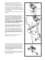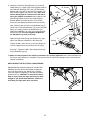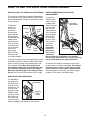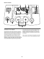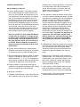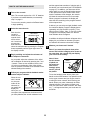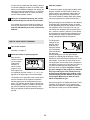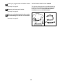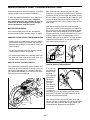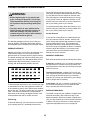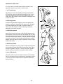
1
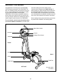
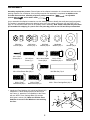
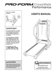
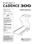
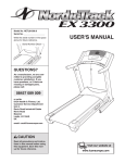
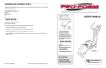
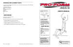
Model No. PFEVEL34020
Serial No.
USER’S MANUAL
Serial
Number
Decal
QUESTIONS?
As a manufacturer, we are committed to providing complete
customer satisfaction. If you have
questions, or if there are missing
or damaged parts, please call:
08457 089 009
Or write:
ICON Health & Fitness, Ltd.
Customer Service Department
Unit 4
Revie Road Industrial Estate
Revie Road
Beeston
Leeds, LS118JG
UK
email: [email protected]
CAUTION
Read all precautions and instructions in this manual before using
this equipment. Keep this manual
for future reference.
Visit our website at
www.iconeurope.com
TABLE OF CONTENTS
IMPORTANT PRECAUTIONS . . . . . . . . . . . . . . . . . . . . . . . . . . . . . . . . . . . . . . . . . . . . . . . . . . . . . . . . . . . . .3
BEFORE YOU BEGIN . . . . . . . . . . . . . . . . . . . . . . . . . . . . . . . . . . . . . . . . . . . . . . . . . . . . . . . . . . . . . . . . . . .4
ASSEMBLY . . . . . . . . . . . . . . . . . . . . . . . . . . . . . . . . . . . . . . . . . . . . . . . . . . . . . . . . . . . . . . . . . . . . . . . . . . .5
HOW TO USE THE ELLIPTICAL CROSSTRAINER . . . . . . . . . . . . . . . . . . . . . . . . . . . . . . . . . . . . . . . . . . . . .9
MAINTENANCE AND TROUBLESHOOTING . . . . . . . . . . . . . . . . . . . . . . . . . . . . . . . . . . . . . . . . . . . . . . . . .15
CONDITIONING GUIDELINES . . . . . . . . . . . . . . . . . . . . . . . . . . . . . . . . . . . . . . . . . . . . . . . . . . . . . . . . . . . .16
PART LIST . . . . . . . . . . . . . . . . . . . . . . . . . . . . . . . . . . . . . . . . . . . . . . . . . . . . . . . . . . . . . . . . . . . . . . . . . . .18
EXPLODED DRAWING . . . . . . . . . . . . . . . . . . . . . . . . . . . . . . . . . . . . . . . . . . . . . . . . . . . . . . . . . . . . . . . . .19
ORDERING REPLACEMENT PARTS . . . . . . . . . . . . . . . . . . . . . . . . . . . . . . . . . . . . . . . . . . . . . . . .Back Cover
PROFORM is a registered trademark of ICON Health & Fitness, Inc.
2
IMPORTANT PRECAUTIONS
WARNING:
To reduce the risk of serious injury, read the following important precautions before using the elliptical crosstrainer.
1. Read all instructions in this manual before
using the elliptical crosstrainer.
8. Always hold the handgrip pulse sensor or the
handlebars when mounting, dismounting, or
using the elliptical crosstrainer.
2. It is the responsibility of the owner to ensure
that all users of the elliptical crosstrainer
are adequately informed of all precautions.
9. The pulse sensor is not a medical device.
Various factors may affect the accuracy of
heart rate readings. The pulse sensor is
intended only as an exercise aid in determining heart rate trends in general.
3. Place the elliptical crosstrainer on a level
surface, with a mat beneath it to protect the
floor or carpet. Keep the elliptical crosstrainer indoors, away from moisture and dust.
10. Keep your back straight when using the elliptical crosstrainer; do not arch your back.
4. Inspect and properly tighten all parts regularly. Replace any worn parts immediately.
11. If you feel pain or dizziness at any time
whilst exercising, stop immediately and
begin cooling down.
5. Keep children under 12 and pets away from
the elliptical crosstrainer at all times.
12. When you stop exercising, allow the pedals
to slowly come to a stop.
6. The elliptical crosstrainer should not be
used by persons weighing more than 114 kg
(250 lbs).
13. The elliptical crosstrainer is intended for
home use only. Do not use the elliptical
crosstrainer in a commercial, rental, or institutional setting.
7. Wear appropriate exercise clothing when
using the elliptical crosstrainer. Always wear
athletic shoes for foot protection.
WARNING:
Before beginning this or any exercise program, consult your physician.
This is especially important for persons over the age of 35 or persons with pre-existing health problems. Read all instructions before using. ICON assumes no responsibility for personal injury or
property damage sustained by or through the use of this product.
3
BEFORE YOU BEGIN
tions after reading this manual, please call our
Customer Service Department at 08457 089 009. To
help us assist you, please note the product model number and serial number before calling. The model number is PFEVEL34020. The serial number can be found
on a decal attached to the elliptical crosstrainer (see the
front cover of this manual for the location of the decal).
Congratulations for selecting the new PROFORM®
750 RX elliptical crosstrainer. The PROFORM® 750
RX is an incredibly smooth exerciser that moves your
feet in a natural elliptical path, minimising the impact
on your knees and ankles. And the unique
PROFORM® 750 RX features adjustable resistance
and an easy-to-use console to help you get the most
from your exercise. Welcome to a whole new world of
natural, elliptical-motion exercise from PROFORM.
Before reading further, please familiarise yourself with
the parts that are labelled in the drawing below.
For your benefit, read this manual carefully before
you use the elliptical crosstrainer. If you have ques-
Water Bottle Holder*
Bookrack
Console
Handgrip Pulse Sensor
Handlebar
FRONT
Pedal
BACK
Wheel
Pedal Disk
Pedal Spring
LEFT SIDE
*No water bottle
is included
4
ASSEMBLY
Assembly requires two persons. Place all parts of the elliptical crosstrainer in a cleared area and remove the
packing materials. Do not dispose of the packing materials until assembly is completed. In addition to the
included allen wrenches, assembly requires a phillips screwdriver
, an adjustable
spanner
, and a rubber mallet
.
As you assemble the elliptical crosstrainer, use the drawings below to identify the small parts used in assembly.
The number in parenthesis below each drawing refers to the key number of the part, from the PART LIST on
page 18. The second number refers to the quantity used in assembly. Note: Some small parts may have been
pre-assembled for shipping. If a part is not in the parts bag, check to see if it has been pre-assembled.
M8 Nylon
Locknut (38)–4
M4 x 16mm
Screw (52)–2
M10 Nylon
Locknut (33)–4
M6 x 25mm
Screw (7)–1
M10 Split
Washer (59)–6
M8 x 19mm Button
Screw (56)–2
M10
Washer (78)–2
M10 x 27mm
Pedal Bolt (80)–2
Spring Bracket
Washer (35)–2
M10 Bolt Set (74)–2
M8 x 45mm Button Bolt (50)–4
M10 x 27mm
Patch Screw (40)–2
Handlebar
Washer (55)–2
M10 x 27mm
Button Screw (67)–6
M10 x 75mm Carriage Bolt (34)–4
1. Identify the Front Stabiliser (10), which has Wheels (22)
attached to it. Whilst another person lifts the front of
the Frame (1), attach the Front Stabiliser to the Frame
with two M10 x 75mm Carriage Bolts (34) and two
M10 Nylon Locknuts (33). Make sure that the Front
Stabiliser is turned so the Wheels are not touching
the floor.
1
22
34
22
1
34
10
5
33
2. Whilst another person lifts the back of the Frame (1),
attach the Rear Stabiliser (9) to the Frame with two
M10 x 75mm Carriage Bolts (34) and two M10 Nylon
Locknuts (33).
2
33
9
33
1
34
3. Whilst another person holds the Upright (2) in the position shown, connect the Extension Wire Harness (44)
to the Wire Harness (79). Carefully pull the upper
end of the Extension Wire Harness to remove any
slack. Whilst holding the upper end of the
Extension Wire Harness, insert the Upright into the
Frame (1). Do not pinch the Wire Harnesses.
3
67
Next, turn the Upright Knob (43) counterclockwise several turns. Pull the Knob, slide the Upright (2) down
until the Knob is aligned with one of the four adjustment holes, and then release the Knob. Do not tighten
the Knob yet.
59
2
Adjustment
Holes
Feed the upper end of the Extension Wire Harness (44)
through the Upright Extension (73). Attach the Upright
Extension to the Upright (2) with three M10 x 27mm
Button Screws (67) and three M10 Split Washers (59).
4. Connect the wire harness on the Handgrip Pulse
Sensor (29) to the indicated wire harness on the
Console (23). Insert both wire harnesses into the opening in the bottom of the Console. Next, insert the metal
tube on the Handgrip Pulse Sensor into the opening in
the bottom of the Console. Be careful not to pinch
the wire harnesses.
Make sure the
Wire Harnesses
73
(44, 79) do not
get pinched and
damaged during
59
this step.
67
44
1
44
79
43
4
23
52
23
Bracket
52
Tube
See the inset drawing. Align the holes in the bracket on
the Console (23) with the holes in the metal tube on
the Handgrip Pulse Sensor (29). Tighten two M4 x
16mm Screws (52) through the bracket into the tube as
shown.
Tube
29
Wire Harnesses
5. The Console (23) requires four 1.5V “D” batteries;
alkaline batteries are recommended. Press the tab on
the battery cover, and lift off the battery cover. Insert
four batteries into the battery compartment. Make sure
that the batteries are oriented as shown by the diagram inside the battery compartment. Reattach the
battery cover.
5
Battery
Cover
Tab
Batteries
23
6
29
6. Whilst another person holds the Console (23) in the
position shown, connect the wire harness on the
Console to the Extension Wire Harness (44). Insert the
excess wire harness into the Upright Extension (73).
6
Bookrack
23
Attach the Console (23) to the Upright Extension (73)
with three M10 x 27mm Button Screws (67) and three
M10 Split Washers (59). Be careful to avoid pinching
the wire harnesses.
Wire Harness
Snap the bookrack onto the Console (23) in the indicated location.
7. Identify the Left Handlebar (6), which is marked with a
sticker. Insert the Left Handlebar into one of the
Handlebar Legs (5); make sure that the Handlebar
Leg is turned so the hexagonal holes are on the
indicated side. Attach the Left Handlebar to the
Handlebar Leg with two M8 x 45mm Button Bolts (50)
and two M8 Nylon Locknuts (38). Make sure that the
Nylon Locknuts are inside of the hexagonal holes.
Do not fully tighten the Button Bolts yet.
44
67
67
59
59
67
73
7
Grease
Apply a light coat of the included grease to the left axle
on the Upright (2) and inside of the two Small
Handlebar Bushings (49) in the Left Handlebar (6).
8
6
55
Carefully slide an Upright Spacer (48), a Handlebar
Spacer (47), the Left Handlebar (6), and a Handlebar
Cap (46) onto the left axle on the Upright (2) as shown.
Slide a Handlebar Washer (55) onto an M8 x 19mm
Button Screw (56), and tighten the Button Screw into the
axle.
48
46
47
49
38
56
5
50
Hexagonal
Holes
Assemble the Right Handlebar (8) and the other
Handlebar Leg (5) in the same way.
5
8. Identify the left Pedal Spring (11), which is marked with
a sticker. Attach the Left Pedal (13) to the left Pedal
Spring with an M10 x 27mm Pedal Bolt (80), an M10
Washer (78), and a Pedal Knob (81) as shown. Note:
The Left Pedal can be attached in several positions
using the five positions in the Left Pedal and the three
holes in the Pedal Spring.
8
80
13
11
Attach the Right Pedal (not shown) in the same way.
Make sure that both Pedals are in the same hole and in
the same pedal position.
78
81
7
2
9. Identify the Left Rear Spring Bracket (12) on the left
Pedal Spring (11). Apply a light coat of grease inside of
the Pedal Arm Bushings (37) in the Left Rear Spring
Bracket and to the axle on the left Disc Crossbar (16).
Slide a Spring Spacer (63) onto the axle; make sure
that the Spring Spacer is turned so the flat side is
facing the elliptical crosstrainer. Next, slide the Left
Rear Spring Bracket onto the axle. Slide a Spring
Bracket Washer (35) onto an M10 x 27mm Patch
Screw (40), and tighten the Patch Screw into the axle.
Next, hold the lower end of the left Handlebar Leg (5)
inside of the Front Spring Bracket (76) on the left Pedal
Spring (11). Apply grease to an M10 Bolt Set (74).
Attach the Handlebar Leg to the Front Spring Bracket
with the Bolt Set. Do not overtighten the Bolt Set;
the Handlebar Leg must pivot freely.
Attach the right Pedal Spring (not shown) to the right
side of the elliptical crosstrainer in the same way.
9
16, Grease
37,
Grease
11
63
12
40
35
2
43
7
5
Grease
Tighten the M6 x 25mm Screw (7) into the Upright (2).
Turn the Upright Knob (43) clockwise until it is tight.
74
74
76
11
See step 7. Tighten the M8 x 45mm Button Bolts (50)
in the Handlebar Legs (5).
10. Make sure that all parts of the elliptical crosstrainer are properly tightened. Note: Some hardware may
be left over after assembly is completed. To protect the floor or carpet from damage, place a mat under the
elliptical crosstrainer.
HOW TO MOVE THE ELLIPTICAL CROSSTRAINER
Stand behind the elliptical crosstrainer, hold the Rear
Stabiliser (9) firmly, and lift the elliptical crosstrainer
until it can be moved on the Wheels (22). Carefully
move the elliptical crosstrainer to the desired location
and then lower it. CAUTION: To decrease the possibility of injury, bend your legs and keep your back
straight as you lift the Rear Stabiliser; make sure
to lift with your legs rather than your back.
22
9
8
HOW TO USE THE ELLIPTICAL CROSSTRAINER
HOW TO ADJUST THE PEDALS AND THE UPRIGHT
HOW TO EXERCISE ON THE ELLIPTICAL
CROSSTRAINER
The motion of the elliptical crosstrainer is determined
by the positions of the pedals and the upright. Follow
the instructions below to adjust the motion of the elliptical crosstrainer.
To adjust the
pedals, first
remove the
pedal knob
beneath each
pedal. Slide the
pedals forward
or backward and
reattach each
pedal using one
of the five holes
in the pedal and
one of the three
holes in the
pedal spring.
Make sure that
both pedals are
in the same position.
Upright
To mount the
elliptical crosstrainer, hold the
Handgrip
handgrip pulse
Pulse
Sensor
sensor and step
onto the pedal
that is in the
lowest position.
Then, step onto
the other pedal.
Pedals
Push the pedals until they
begin to move
with a continuous motion.
Note: The
pedal disks
Pedal Disk
can turn in
either direction. It is recommended
that you move the pedal disks in the direction
shown by the arrow; however, for variety, you may
turn the pedal disks in the opposite direction.
Upright
Knob
Pedal
Pedal
Knob
Pedal
Spring
To adjust the upright, first turn the upright knob counterclockwise a few turns to loosen it. Next, pull the knob,
raise or lower the upright to the desired height, and
then release the knob. Move the upright up and
down slightly until the pin on the knob snaps into
one of the four adjustment holes in the upright.
Make sure that the upright is not resting on top of
the pin. Then, turn the knob clockwise until it is tight.
To dismount the elliptical crosstrainer, wait until the
pedals come to a complete stop. Note: The elliptical
crosstrainer does not have a free wheel; the pedals will continue to move until the flywheel stops.
When the pedals are stationary, step off the highest
pedal first. Then, step off the lowest pedal.
HOW TO USE THE HANDLEBARS
The handlebars
are designed to
Handlebars
add upper-body
exercise to your
workouts. As you
exercise, push
and pull the hanHandgrip
dlebars to work
Pulse
your arms, shoulSensor
ders, and back.
To exercise only
your lower body,
hold the handgrip pulse sensor as you exercise.
9
CONSOLE DIAGRAM
A
B
C
D
E
F
G
H
I
K
J
FEATURES OF THE CONSOLE
The advanced console offers a selection of features
designed to make your workouts more enjoyable and
effective. When the manual mode of the console is
selected, the resistance of the elliptical crosstrainer
can be adjusted with a touch of a button. As you
pedal, the console will provide continuous exercise
feedback. You can even measure your heart rate using
the built-in handgrip pulse sensor. Note: See page 14
for information about an optional chest pulse sensor.
10
The console also offers six workout programs. Each
program automatically changes the resistance of the
elliptical crosstrainer and prompts you to increase or
decrease your pace as it guides you through an effective workout.
Note: If there is a thin sheet of clear plastic on the face
of the console, remove it before operating the console.
CONSOLE DESCRIPTION
resistance level, calories, fat calories, or heart rate)
is currently shown. Note: When the distance is
shown, the word “Miles” or the letters “Kms” will
appear; when your speed is shown, the letters
“MPH” or “Km/H” will appear.
See the drawing on page 10.
A. Exercise feedback display—This display features
seven modes that give you instant exercise feedback: your current speed, the elapsed time (or the
time remaining in a workout program), the distance
that you have pedaled, the resistance level, the
approximate number of calories you have burned,
the approximate number of fat calories you have
burned (see FAT BURNING on page 16), and your
heart rate (when you use the handgrip pulse sensor
or the optional chest pulse sensor). If the scan
mode is selected, the display will change from one
mode to the next every few seconds. Or, you can
select a single mode for continuous display.
G. Pace indicators—When the manual mode is selected, only the left pace indicator will appear. This indicator shows your pedaling pace. As you increase or
decrease your pace, the indicator will increase or
decrease in height. When a workout program is
selected, both pace indicators will appear. The left
indicator will show your actual pedaling pace, and
the right indicator will show a target pace. During
the program, the target pace will periodically
change; as the right indicator changes in height,
simply adjust your pace so that both indicators are
at the same height. Important: The target pace is
a goal pace. Your actual pace may be slower
than the target pace, especially during the first
few months of your exercise program. Make
sure to pedal at a pace that is comfortable for
you.
Note: The console can show speed and distance
in either miles or kilometres. To change the unit
of measurement, hold down the On/Reset button
for six seconds. The mode indicators (see F on
this page) will show which unit of measurement
is selected. When the batteries are replaced, it
may be necessary to reselect the desired unit of
measurement.
H. On/Reset button—When the console is off, pressing
this button will turn on the display. When the console
is on, pressing this button will reset the display.
This button is also used to select the unit of measurement for speed and distance (see A on this
page).
B. Increase and decrease arrows—During workout
programs, these arrows will prompt you to increase
or decrease your pace to match the target pace.
C. Manual mode/program indicators—When a workout
program is selected, the upper right corner of the
display will show a 1, 2, 3, 4, 5, or 6, depending on
which program is selected. When the manual mode
is selected, the upper right corner will be blank.
I. Display button—This button is used to select the
feedback modes. The modes will be selected in the
following order: scan, speed, time, distance, resistance level, calories, fat calories, and heart rate
(when the handgrip pulse sensor or the optional
chest pulse sensor is used).
D. Program profiles—These profiles show how the
resistance of the elliptical crosstrainer and the target
pace will change during workout programs.
J. + and – buttons—These buttons control the resistance of the elliptical crosstrainer. There are ten
resistance levels; level 10 is the most challenging.
E. Warnings—See page 3.
K. Program button—This button is used to select the
manual mode and workout programs.
F. Feedback mode indicators—These indicators show
which feedback mode (scan, speed, time, distance,
11
and the approximate numbers of calories and of
fat calories you have burned (see FAT BURNING
on page 16). In addition, your heart rate will be
shown when you use the handgrip pulse sensor
or the optional chest pulse sensor. Note: Each
time the resistance level changes, the console
will show the resistance level for six seconds.
When a program is selected, the display will
show the time remaining in the program instead
of the elapsed time.
HOW TO USE THE MANUAL MODE
1
Turn on the console.
Note: The console requires four 1.5V “D” batteries.
If you have not installed batteries, see assembly
step 5 on page 6.
To turn on the console, press the On/Reset button
or begin pedalling.
2
If desired, you can select a single feedback mode
for continuous display. Press the Display button
repeatedly until only the MPH (or Km/H), Time,
Miles (or Kms), Resist., Cals., or Fat Cals. indicator appears in the display. Make sure that the
Scan indicator does not appear.
Select the manual mode.
Each time the
This corner
console is
should be blank
turned on, the
manual mode
will be selected. If a workout
program has
been selected,
select the manual mode by pressing the Program
button repeatedly until the upper right corner of
the display is blank.
3
In addition, the left pace indicator will appear in the
display. As you increase or decrease your pace,
the indicator will increase or decrease in height.
5
Note: If you wear the optional chest pulse
sensor and hold the handgrip pulse sensor at
the same time, the console may not display
your heart rate accurately.
Begin pedalling and adjust the resistance of
the elliptical crosstrainer.
Note: If there
are thin sheets
of plastic on
the metal contacts on the
handgrip pulse
sensor, peel off
the plastic.
As you pedal, adjust the resistance of the elliptical crosstrainer as desired by pressing the + and
– buttons. There are ten resistance levels; level
10 is the most challenging. Note: After the buttons are pressed, it will take a few seconds for the
selected setting to be reached.
4
Measure your heart rate if desired.
Follow your progress with the feedback modes
and the left pace indicator.
Metal
Contacts
To use the handgrip pulse sensor, place your
hands on the metal contacts. Your palms must be
on the upper contacts and your fingers must be
touching the lower contacts. Avoid moving your
hands. When your pulse is detected, the heartshaped indicator in the display will flash each
time your heart beats. After a moment, two dashes (– –) will appear and then your heart rate will
be shown.
When the console is turned
on, the scan
mode will be
selected. As
you pedal, the
display will
show your current speed, the elapsed time, the distance that
you have pedalled, the current resistance level,
12
For the most accurate heart rate reading, continue
to hold the handgrips for about 15 seconds. Note:
When you first hold the handgrips, the display will
show your heart rate continuously for 15 seconds.
The display will then show your heart rate along
with the other feedback modes.
6
When you are finished exercising, the console
will automatically turn off after a few minutes.
To start the program, simply begin pedaling. Each
program consists of either twenty or thirty, oneminute periods. One resistance setting and one
pace setting are programmed for each period.
(The same resistance setting and/or pace setting
may be programmed for consecutive periods.)
The target pace
settings for the
program will be
shown by the
right pace indicator in the display.
Increase Arrow
(The left indicator
will show your
actual pedaling pace.) As the right indicator
changes in height during the program, simply
adjust your pace so that both indicators are at the
same height. If your pace is slower than the current target pace, the increase arrow will appear in
the display to prompt you to increase your pace; if
your pace is faster than the target pace, the
decrease arrow will appear. Important: The target pace settings for the program are intended
only to provide a goal. Your actual pace may
be slower than the target pace settings, especially during the first few months of your exercise program. Make sure to pedal at a pace
that is comfortable for you.
HOW TO USE A PRESET PROGRAM
Turn on the console.
See step 1 on page 12.
2
Start the program.
During the program, the resistance of the elliptical
crosstrainer will automatically change as shown
by the applicable profile on the console. If the current resistance level is too high or too low, you
can change the resistance level by pressing the +
and – buttons. However, when the current period
of the program is completed, the resistance level
will automatically change if a different resistance
setting is programmed for the next period.
If the pedals are not moved and the console buttons are not pressed for a few minutes, the console will automatically turn off to conserve the
batteries.
1
3
Select one of the six preset programs.
Each time the
console is turned
on, the manual
mode will be
selected. To
select a preset
program, press
the Program button repeatedly until the number 1, 2, 3, 4, 5, or 6
appears in the upper right corner of the display.
The profiles on the right side of the console show
how the resistance of the elliptical crosstrainer
and the target pace will change during the programs. For example, profile number 3 shows that
during program 3, both the resistance and the target pace will gradually increase during the first
half of the program, and then decrease during the
last half.
During the program, the display will show the time
remaining in the program. If you continue pedalling after the program is completed, the display
will continue to show your exercise feedback.
13
4
5
Follow your progress with the feedback modes.
THE OPTIONAL CHEST PULSE SENSOR
See step 4 on page 12.
The optional chest pulse sensor provides hands-free
operation and continuously monitors your heart rate
during your workouts. To purchase the optional
chest pulse sensor, call 08457 089 009.
Measure your heart rate if desired.
See step 5 on page 12.
6
When you are finished exercising, the console
will automatically turn off after a few minutes.
See step 6 on page 13.
14
MAINTENANCE AND TROUBLESHOOTING
Inspect and tighten all parts of the elliptical crosstrainer
regularly. Replace any worn parts immediately.
Next, remove the four Screws (51) from the right
Pedal Disc (15), and slide the Pedal Disc off. Remove
all Screws (52, 64) from the Right Side Shield (4) and
the two Screws (77) from beneath the Pedal Disc, and
remove the Right Side Shield. Remove all Screws
(52) from the Left Side Shield (3) and remove the Left
Side Shield.
To clean the elliptical crosstrainer, use a damp cloth
and a small amount of mild detergent. Important:
Keep liquids away from the console and keep the
console out of direct sunlight. During storage,
remove the batteries from the console.
Next, see the drawing below and locate the Reed
Switch (53). Loosen, but do not remove, the indicated
M4 x 16mm Screw (52). Slide the Reed Switch slightly
toward or away from the Magnet (58) on the flywheel.
Retighten the Screw. Turn the left Pedal Disc (15) for a
moment. Repeat until the console displays correct
feedback. When the Reed Switch is correctly adjusted,
reattach the Side Shields (3, 4), the right Pedal Disc
(15), and the Pedal Springs (11).
BATTERY REPLACEMENT
If the console display becomes dim, the batteries
should be replaced. See assembly step 5 on page 6.
HANDGRIP PULSE SENSOR TROUBLESHOOTING
• Avoid moving your hands whilst using the handgrip
pulse sensor; excessive movement may interfere
with heart rate readings. Do not hold the metal contacts too tightly.
• For the most accurate heart rate reading, hold the
metal contacts for about 15 seconds.
58
• For optimal performance of the handgrip pulse sensor, clean the metal contacts with a soft cloth—do
not use alcohol, abrasives, or chemicals.
15
53
52
HOW TO ADJUST THE REED SWITCH
HOW TO ADJUST THE DRIVE BELT
If the console does not display correct feedback, the
reed switch should be adjusted. To do this, you must
remove the Pedal Springs (11), the right Pedal Disc
(15), and the Side Shields (3, 4). See step 9 on page
8 and remove the Pedal Springs.
3
4
If you can feel
the pedals slip
whilst you are
pedalling,
even when the
resistance is
adjusted to
68
the highest
level, the
Drive Belt (19)
62
19
may need to
be adjusted.
To adjust the
Drive Belt, you must first remove both side shields.
See HOW TO ADJUST THE REED SWITCH at the
left and remove the side shields.
64
15
11
52
77
64
11
Next, loosen the M8 x 22mm Flat Head Screw (68)
and turn the M10 x 70mm Bolt (62) until the Drive Belt
(19) is tight. When the Drive Belt is tight, tighten the
Flat Head Screw. Reattach the side shields.
51
77
64
52
51
15
CONDITIONING GUIDELINES
During the first few minutes of exercise, your body
uses easily accessible carbohydrate calories for energy. Only after the first few minutes of exercise does
your body begin to use stored fat calories for energy.
If your goal is to burn fat, adjust the intensity of your
exercise until your heart rate is near the lowest number in your training zone as you exercise.
WARNING:
• Before beginning this or any exercise program, consult your physician. This is especially important for persons over the age of
35 or persons with pre-existing health problems.
For maximum fat burning, adjust the intensity of your
exercise until your heart rate is near the middle number in your training zone as you exercise.
• The pulse sensor is not a medical device.
Various factors may affect the accuracy of
heart rate readings. The pulse sensor is
intended only as an exercise aid in determining heart rate trends in general.
Aerobic Exercise
If your goal is to strengthen your cardiovascular system, your exercise must be “aerobic.” Aerobic exercise is activity that requires large amounts of oxygen
for prolonged periods of time. This increases the
demand on the heart to pump blood to the muscles,
and on the lungs to oxygenate the blood. For aerobic
exercise, adjust the intensity of your exercise until
your heart rate is near the highest number in your
training zone as you exercise.
The following guidelines will help you to plan your
exercise program. Remember that proper nutrition
and adequate rest are essential for successful results.
EXERCISE INTENSITY
Whether your goal is to burn fat or to strengthen your
cardiovascular system, the key to achieving the
desired results is to exercise with the proper intensity.
The proper intensity level can be found by using your
heart rate as a guide. The chart below shows recommended heart rates for fat burning, maximum fat
burning, and cardiovascular (aerobic) exercise.
WORKOUT GUIDELINES
Each workout should include the following three parts:
A warm-up, consisting of 5 to 10 minutes of stretching
and light exercise. A proper warm-up increases your
body temperature, heart rate, and circulation in preparation for exercise.
Training zone exercise, consisting of 20 to 30 minutes of exercising with your heart rate in your training
zone. (During the first few weeks of your exercise
program, do not keep your heart rate in your training
zone for longer than 20 minutes.)
A cool-down, with 5 to 10 minutes of stretching. This
will increase the flexibility of your muscles and will
help to prevent post-exercise problems.
To find the proper heart rate for you, first find your age
on the bottom line of the chart (ages are rounded off
to the nearest ten years). Next, find the three numbers
above your age. The three numbers are your “training
zone.” The lower two numbers are recommended
heart rates for fat burning; the highest number is the
recommended heart rate for aerobic exercise.
EXERCISE FREQUENCY
To maintain or improve your condition, complete three
workouts each week, with at least one day of rest
between workouts. After a few months of regular exercise, you may complete up to five workouts each week
if desired. The key to success is to make exercise a
regular and enjoyable part of your everyday life.
Fat Burning
To burn fat effectively, you must exercise at a relatively low intensity level for a sustained period of time.
16
SUGGESTED STRETCHES
The correct form for several basic stretches is shown at the
right. Move slowly as you stretch—never bounce.
1
1. Toe Touch Stretch
Stand with your knees bent slightly and slowly bend forward
from your hips. Allow your back and shoulders to relax as you
reach down toward your toes as far as possible. Hold for 15
counts, then relax. Repeat 3 times. Stretches: Hamstrings, back
of knees and back.
2
2. Hamstring Stretch
Sit with one leg extended. Bring the sole of the opposite foot
toward you and rest it against the inner thigh of your extended
leg. Reach toward your toes as far as possible. Hold for 15
counts, then relax. Repeat 3 times for each leg. Stretches:
Hamstrings, lower back and groin.
3. Calf/Achilles Stretch
With one leg in front of the other, reach forward and place your
hands against a wall. Keep your back leg straight and your back
foot flat on the floor. Bend your front leg, lean forward and move
your hips toward the wall. Hold for 15 counts, then relax. Repeat
3 times for each leg. To cause further stretching of the achilles
tendons, bend your back leg as well. Stretches: Calves, achilles
tendons and ankles.
3
4
4. Quadriceps Stretch
With one hand against a wall for balance, reach back and grasp
one foot with your other hand. Bring your heel as close to your
buttocks as possible. Hold for 15 counts, then relax. Repeat 3
times for each leg. Stretches: Quadriceps and hip muscles.
5
5. Inner Thigh Stretch
Sit with the soles of your feet together and your knees outward.
Pull your feet toward your groin area as far as possible. Hold for
15 counts, then relax. Repeat 3 times. Stretches: Quadriceps
and hip muscles.
17
PART LIST—Model No. PFEVEL34020
Key No. Qty.
1
2
3
4
5
6
7
8
9
10
11
12
13
14
15
16
17
18
19
20
21
22
23
24
25
26
27
28
29
30
31
32
33
34
35
36
37
38
39
40
41
42
43
1
1
1
1
2
1
1
1
1
1
2
1
1
1
2
2
1
1
1
2
2
2
1
2
1
2
2
1
1
2
2
1
5
4
2
12
4
5
2
2
2
4
1
Description
Key No. Qty.
Frame
Upright
Left Side Shield
Right Side Shield
Handlebar Leg
Left Handlebar
M6 x 25mm Screw
Right Handlebar
Rear Stabiliser
Front Stabiliser
Pedal Spring
Left Rear Spring Bracket
Left Pedal
Right Pedal
Pedal Disc
Disc Crossbar
Flywheel
Side Shield Bracket
Drive Belt
Rear Endcap
Front Endcap
Wheel
Console
Handgrip
Idler Bracket
Idler Washer
Idler Bearing
Idler Axle
Handgrip Pulse Sensor
Large Snap Ring
Large Bearing
Pedal Axle
M10 Nylon Locknut
M10 x 75mm Carriage Bolt
Spring Bracket Washer
M6 x 33.5mm Bolt
Pedal Arm Bushing
M8 Nylon Locknut
M10 Washer
M10 x 27mm Patch Screw
M6 x 72mm Bolt
M5 Washer
Upright Knob
44
45
46
47
48
49
50
51
52
53
54
55
56
57
58
59
60
61
62
63
64
65
66
67
68
69
70
71
72
73
74
75
76
77
78
79
80
81
82
#
#
#
1
1
2
2
2
4
4
8
12
1
1
2
2
1
1
6
4
2
1
2
4
1
16
6
1
1
1
2
2
1
2
12
2
2
5
1
2
2
2
1
1
1
R0502A
Description
Extension Wire Harness
Resistance Control Motor
Handlebar Cap
Handlebar Spacer
Upright Spacer
Small Handlebar Bushing
M8 x 45mm Button Bolt
M6 x 30mm Screw
M4 x 16mm Screw
Reed Switch/Wire
Cable Clamp
Handlebar Washer
M8 x 19mm Button Screw
M10 Flat Head Bolt
Magnet
M10 Split Washer
Large Handlebar Arm Bushing
5/16” x 25.4mm Hex Bolt
M10 x 70mm Bolt
Spring Spacer
M4 x 25mm Screw
Upright Bushing
M6 Nylon Locknut
M10 x 27mm Button Screw
M8 x 22mm Flat Head Screw
Push Nut
Right Rear Spring Bracket
M5 x 16mm Self-tapping Screw
M5 x 12mm Screw
Upright Extension
M10 Bolt Set
M6 Washer
Front Spring Bracket
M6 x 18mm Screw
M10 Washer
Wire Harness
M10 x 27mm Pedal Bolt
Pedal Knob
M5 x 14mm Self-tapping Screw
Allen Wrench
Grease
User’s Manual
Note: # indicates a non-illustrated part. Specifications are subject to change without notice.
18
EXPLODED DRAWING—Model No. PFEVEL34020
R0502A
64
23
59
24
52
77
67
67
4
73
59
52
8
59 67
77
24
52
59
67
3
29
6
48
49
46
47
49
47
48
49
46
50
52
49
80
38
56 55
36
38
2
50
76
75
52
5
66
44
60
74 65
60
60
41
33
22
10
22
52
15
61
36
66
1
33
66
34
66
36
81
40
11
20
45
13
78
63
19
12
37
37
35
66
75
19
52
20
42
75
51
18
9
79
35
37
70
75
66
32
71 72
51
40
61
33
16
62
76
31
30
15
54
80
37
51
51
82 31
51
63
11
17
16
78 26
69
78
25
68 28
30
82
38
33
53
81
36
39 27
26
21
66
21
39 78
58
57
43
66
14
78
33
74
7
74
41
74
60
5
34
64
56
55
ORDERING REPLACEMENT PARTS
To order replacement parts, contact the ICON Health & Fitness, Ltd. office, or write:
ICON Health & Fitness, Ltd.
Customer Service Department
Unit 4, Revie Road Industrial Estate
Revie Road
Beeston
Leeds, LS118JG
UK
Tel:
08457 089 009
Outside the UK: 0 (044) 113 387 7133
Fax: 0 (044) 113 387 7125
To help us assist you, please be prepared to give the following information:
• the MODEL NUMBER of the product (PFEVEL34020)
• the NAME of the product (PROFORM® 750 RX elliptical crosstrainer)
• the SERIAL NUMBER of the product (see the front cover of this manual)
• the KEY NUMBER and DESCRIPTION of the part(s) (see page 18 of this manual)
Part No. 184752 R0502A
Printed in China © 2002 ICON Health & Fitness, Inc.